EP1803007B1 - Poling of optical fibres and the like - Google Patents
Poling of optical fibres and the like Download PDFInfo
- Publication number
- EP1803007B1 EP1803007B1 EP05777231A EP05777231A EP1803007B1 EP 1803007 B1 EP1803007 B1 EP 1803007B1 EP 05777231 A EP05777231 A EP 05777231A EP 05777231 A EP05777231 A EP 05777231A EP 1803007 B1 EP1803007 B1 EP 1803007B1
- Authority
- EP
- European Patent Office
- Prior art keywords
- fiber
- electrodes
- poling
- anyone
- core
- Prior art date
- Legal status (The legal status is an assumption and is not a legal conclusion. Google has not performed a legal analysis and makes no representation as to the accuracy of the status listed.)
- Expired - Lifetime
Links
Images



Classifications
-
- G—PHYSICS
- G02—OPTICS
- G02B—OPTICAL ELEMENTS, SYSTEMS OR APPARATUS
- G02B6/00—Light guides; Structural details of arrangements comprising light guides and other optical elements, e.g. couplings
- G02B6/10—Light guides; Structural details of arrangements comprising light guides and other optical elements, e.g. couplings of the optical waveguide type
- G02B6/105—Light guides; Structural details of arrangements comprising light guides and other optical elements, e.g. couplings of the optical waveguide type having optical polarisation effects
-
- G—PHYSICS
- G02—OPTICS
- G02F—OPTICAL DEVICES OR ARRANGEMENTS FOR THE CONTROL OF LIGHT BY MODIFICATION OF THE OPTICAL PROPERTIES OF THE MEDIA OF THE ELEMENTS INVOLVED THEREIN; NON-LINEAR OPTICS; FREQUENCY-CHANGING OF LIGHT; OPTICAL LOGIC ELEMENTS; OPTICAL ANALOGUE/DIGITAL CONVERTERS
- G02F1/00—Devices or arrangements for the control of the intensity, colour, phase, polarisation or direction of light arriving from an independent light source, e.g. switching, gating or modulating; Non-linear optics
- G02F1/35—Non-linear optics
- G02F1/355—Non-linear optics characterised by the materials used
- G02F1/3558—Poled materials, e.g. with periodic poling; Fabrication of domain inverted structures, e.g. for quasi-phase-matching [QPM]
Definitions
- the present invention generally relates to the field of permanently inducing an electric field in amorphous materials such as glass, known in the art as "poling".
- Poling involves exposing a material to an intense electric field, usually whilst the material is either subjected to a heating process or a UV irradiation.
- the poling process may effect a change in the optical second-order non-linearity.
- Poling can for example be used for inducing or recording a permanent electric field in an optical fiber, such that it becomes electro-optically active.
- This type of electro-optical fibers are then capable of changing more efficiently its refractive index in response to an applied electrical signal, such that it can be used for purposes of switching or modulating light.
- the optical fiber to be poled comprises a silica cladding, a fiber core and two electrodes.
- the electrodes are arranged in the cladding of the fiber, in parallel with and on opposite sides of the fiber core. A poling voltage across the electrodes generates an electric field for poling the core. Further, the electrodes are preferably arranged close to the fiber core in order to maximize the field strength over the core during poling.
- the recorded (permanently "frozen” into the material) electric field should be as high as possible to create an effective device, e.g. a device which requires a low modulation voltage. Therefore, in order to make efficient components, one attempts to apply as high a voltage as possible during poling, while staying on the safe side of the dielectric breakdown limit. In other words, the strength of the applied electric field during poling is limited by the electric breakdown properties of the material, which hence results in a lower practical limit for the required modulation voltage when the device is used as an active electro-optic component after poling. Electric breakdown through the surrounding air may also be a problem.
- Enami. Y. et. al “Poling of soda-lime glass for hybrid glass/polymer electro-optic modulators" Appl. Phys. Lett., vol. 76, no. 9, pp. 1086-1088 (2000 ) discloses a poling process of soda-lime glasses enabling in-plane poling of electro-optic polymers coated on ion-exchanged channel waveguides fabricated in soda-lime glass for hybrid modulators. Poling is performed by applying a positive voltage on two in-plane electrodes (anodes) with a third backside electrode (cathode) connected to ground.
- the inventors have now found that it is possible to achieve poling of a dielectric material using only one electrode, contained inside the material, and applying a positive potential to this electrode. This might at first seem counter-intuitive, a permanent electric field being induced in the material without the use of both a positive and a negative electrode.
- the inventive method is preferably performed using two electrodes, which extend longitudinally inside an optical fiber with a bias potential of the same polarity (and preferably of substantially the same magnitude) during poling, thus facilitating the recording of a much higher field than if the electrodes had a bias potential of opposite polarity during poling.
- the use of bias potentials of same polarity (and preferably substantially the same magnitude) during poling enables the application of a much higher bias potential with a minimized risk of dielectric breakdown.
- the same two electrodes are conveniently used, after poling, for controlling an optical signal propagating in the fiber, by the application of a control signal across the two electrodes in a conventional way.
- the present invention thus provides a method of inducing a permanent electric field in a dielectric material, in which ions or dipoles may be rearranged under the influence of an applied electric field.
- the core region of an optical fiber is subjected to the poling process, wherein each electrode may be located within the cladding of the fiber.
- the inventive method provides a number of advantages with respect to known poling techniques.
- the use of two anodes disposed on opposite sides of the fiber core allows recording an electric field that is much larger than if the electrodes were used in the conventional way, i.e., one as anode and the other one as cathode.
- the risk of dielectric breakdown during poling is very much reduced. Therefore a much higher poling potential can be used.
- two or more electrodes are used, to which substantially equally large potentials of the same sign (polarity) are applied.
- the use two electrodes applied to essentially the same potential results in one charge distribution being induced near each electrode, and their effects are superimposed.
- the resulting electric field after poling may thereby be essentially doubled.
- the potentials are preferably of equal sign and magnitude, there is essentially no potential difference between the electrodes, and advantageously a negligible risk of dielectric breakdown. Consequently, much higher potentials can be used when poling the material.
- the electrodes may be located within the cladding of the fiber close to the fiber core.
- the induced electric fields at each anode can be made to overlap.
- a nearly twice as strong electric field may be induced in the material between the electrodes, compared to when only one electrode is used and applied to the same potential for the same amount of time.
- the combination of being able to apply much higher electric field during poling and to record a field nearly twice as large compared to the conventional anode/cathode configuration is of course highly useful. There are a number of ways in which this can be taken advantage of.
- the inventors have been able to record a field across the core of a fiber that caused the same effect as a potential difference of 8 kV applied between anode/cathode electrodes of the conventional technique, although the technique used for this achievement was the application during poling of a bias potential of +4.3 kV to both metallic electrodes.
- the same type of fiber was found not to withhold a potential difference between electrodes greater than 5 kV, since electrical breakdown occurred at this potential difference level. Therefore, with the inventive technique, it was possible to record a field across the core of the fiber that exceeded the maximum field that can be applied with external electrodes biased in the conventional way. Further, a similar piece of fiber was poled biasing both electrodes at +7.6 kV and no electrical breakdown was observed. The time needed for poling to be satisfactorily effected was then reduced.
- the potential applied to respective electrode is positive, such that an effective poling of a glassy material, e.g. fused silica can be achieved.
- a glassy material e.g. fused silica
- the dielectric material may advantageously be a core and/or a cladding of an optical fiber, which is provided with two electrodes arranged substantially in parallel with the core of the fiber, suitably within the cladding.
- An equal positive potential is applied to both electrodes, which are arranged on opposite sides of the fiber core and sufficiently close to each other, such that the effect of the induced electric field will strongly overlap each other.
- the core of the fiber is arranged closer to one of the two electrodes. This facilitates the induced field distribution.
- the entire fiber core is located inside the depleted region around one of the anodes. In other words, the border of the depleted region, should preferably not pass through the core of the fiber.
- More than two internal electrodes can also be used when poling the dielectric material. This can advantageously create an even stronger induced electric field compared to poling using two anodes applied to the same potential, since even more charge can be displaced.
- one or more of the electrodes can have a substantially non-elliptical and non-circular cross section in order to create an optimal induced electric field by gathering adjacent to the core of the fiber the negative charge at the edge of the depletion region that remains after poling.
- the poling of the material can be performed under a controlled atmosphere. For example, by providing an increased air humidity, the surrounding air may act more efficiently to ground the outside surface of the dielectric material.
- an electrode formed around the outer surface of a fiber is applied to a negative potential.
- Air or a plasma supplying an excess of charges, present in one or several longitudinal holes inside the fiber electrically grounds the inner surface of said hole, thus acting as an anode for poling.
- the air or plasma in the holes may also be replaced by a liquid or gas, which facilitates the use of the surface of the hole as anode electrode.
- manufacture of such a fiber will be most cost effective.
- the present invention can be used for poling a twin-core fiber. The poling is then effected such that each of the cores will experience a different sign of the inscribed electric field, such that a push-pull configuration is obtained when the device is later driven in operation.
- Figure 1 illustrates a cross section of a twin hole optical fiber, provided with two longitudinal electrodes.
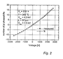
- Figure 2 illustrates the result of a measurement performed on the fiber, after the fiber had been poled using two anodes at equal potential.
- Figure 3 schematically shows two depleted areas after poling has been performed using two anodes at equal potential.
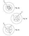
- Figure 4 schematically illustrates different configurations of the longitudinal electrodes.
- Figure 5 schematically illustrates a fiber, comprising two cores, which has been poled using two anodes at equal potential.
- optical fibers can be applied to any dielectric material, wherein an permanent electric field can be induced by the use of an applied potential.
- the fiber used in the experiments was specially designed for poling.
- the preform was manufactured from a 8 mm thick glass tube of fused silica glass with nominally about 1 ppm of sodium.
- the core was created by depositing germanium on the inside of the tube using a Modified Chemical Vapor Deposition process, after which the preform was collapsed and holes drilled. Finally, the preform was drawn to a fiber with an outer diameter of 125 ⁇ m.
- a high temperature acrylate, or in some cases a polyimide, coating 11 was applied to make the fiber heat resistant during electrode insertion and poling, and to keep it transparent after the thermal treatments.
- the fiber 10 was designed to have one of the electrode holes 12 placed closer to the core 14 to ensure good overlap between the core and the poled region.
- the presence of metallic electrodes close to the core may lead to optical losses unless the propagating mode in the fiber is confined close to the core, substantially non-overlapping with the electrodes.
- the diameter of the core was 3.6 ⁇ m and the fiber was a single-mode fiber for 1550 nm.
- the edge-to-edge distance from the core 14 to the nearest hole 12 was 4.6 ⁇ m, and to the farthest hole 13 10.1 ⁇ m.
- the two holes 12, 13 were 29.5 ⁇ m in diameter and had a separation of 18.3 ⁇ m.
- the diameter of the fiber should preferably be a few times larger than the separation between the electrodes.
- the diameter of the fiber may be 4-10 times larger than the separation between the electrodes, such as about 6 times larger.
- the alloy used to create the electrodes 15, 16 consisted of 80 % wt Au and 20 % wt Sn, with a melting point of 280 °C and resistivity 1.6 x 10 -5 ⁇ cm. This alloy was chosen because it can be inserted at 300 °C in molten form and poling can take place with the metal in its solid phase at a temperature of 250-270 °C, which is close to the optimal temperature for poling. Generally, when performing the method disclosed and claimed herein, the temperature of the material should typically be at least 200°C, and preferably at least 250°C.
- the length of the electrodes 15, 16 was 37 cm,. Electric contact with the electrodes was established by side-polishing the fiber and then attaching 20 ⁇ m thick gold coated tungsten wires to the alloy using conductive epoxy.
- a hotplate 17 was used to heat the contacted fiber to 255 °C.
- the fiber was poled by applying a voltage of +4.3 kV to both the electrodes 15, 16. After 155 minutes the heater was switched off and the fiber 10 was allowed to cool down to room temperature with the voltage still applied. All fibers were poled with the high-temperature resistant primary coating 11 in place and unharmed.
- a hotplate for heating the material to be poled
- a furnace or UV-exposure it is also possible to use a furnace or UV-exposure.
- the heated environment around the optical fiber provides for a supply of negative charges, and this is greatly facilitated if the surface of the furnace or hot-plate is sufficiently conductive at the poling temperature.
- a metal surface and a soft glass (soda-lime) surface have both been successfully used as the external ground plane (ground potential) delivering the negative charges.
- the fiber component was used as the active arm of a ⁇ 1 m long, unstabilized 2x2 Mach-Zehnder interferometer (MZI).
- MZI Mach-Zehnder interferometer
- the test result is illustrated in Figure 2 .
- the characterization was carried out at 1550 nm, where the fibers used were single mode.
- EDFA Erbium-Doped Fiber Amplifier
- the MZI consisted of two 3-dB couplers with a standard single-mode fiber as the passive arm.
- the fiber 10 was probed with a 400 V AC peak-to-peak voltage at 1 kHz, which was applied across the two electrodes 15, 16 previously used for poling.
- the peak-to-peak intensity modulation resulting from the AC voltage was recorded for different applied DC voltages.
- the spatial distribution of the effective nonlinearity recorded was studied in order to evaluate the poling procedure.
- the acrylate coating 11 was removed and the fiber was cleaved several times in the - 20 cm long poled region.
- the cleaved ends of the fiber pieces were etched in 40 % hydrofluoric acid (HF) for 45 seconds.
- the fiber pieces were then rinsed in deionized water and dried at 150 °C in air, after which the samples were inspected with an optical phase contrast microscope. Etching revealed, as is schematically illustrated in Figure 3 , that two depletion regions 19, 20 had been created, one around each electrode, the cross section of which were substantially circular.
- the applied positive potential and the accumulation of negative charges forces cations present in the glass to move from the anodes 15, 16 outwardly, towards the negative charges surrounding the cladding 18 such that the area 19, 20 immediately surrounding the anodes are depleted of cations, having a high mobility.
- These depleted regions are soon to a large extent neutralized, either by H + or H 3 O + entering the region, or by electrons from the depleted areas ionized by the large field and entering the anodes.
- Left is only a thin layer of negative charges at the border between the depleted regions 19, 20 and the not yet depleted region. This border is typically 0.5 ⁇ m thick.
- the cladding 18 When the cladding 18 is made of fused silica, mainly Na-ions are displaced.
- Other ions which also have a relatively high mobility in glass are e.g. K + , H + , H 3 O + , Li + and Ag + .
- the induced permanent electric field should be time stable, i.e. should not change substantially over time. Therefore, it might be advantageous to displace ions having a slightly lower mobility, such as K + or Ca 2+ , as this could create a more time stable induced electric field. As poling with two anodes facilitates the use of a higher electric field, this might enable a migration of K or Ca ions. However, the effect noted to date is mainly attributed to the migration of sodium ions and their replacement by hydronium species (H + and H 3 O + ).
- a depletion region of width 9 ⁇ m may be formed around each electrode.
- the two depleted regions 19, 20 will overlap between the electrodes and the negative ions at the border of each depleted region will be accumulated in roughly the same area. Consequently, nearly twice as much charge will accumulate between the electrodes, which means that the permanent electric field induced on either side of the negative charge distribution in the fiber will be nearly twice as large.
- FIG. 4a shows one example of four symmetrically distributed electrodes 15, 16, 21, 22 as shown in Figure 4a .
- Another example is the arrangement of one or several electrodes with a different shape, e.g. a non-circular cross section.
- Figure 4b and 4c shows one and two electrodes 23; 24, 25, respectively, having a crescent shape, with the concave side facing the core or the center of the fiber.
- the fiber By arranging two cores 14, 26 in the fiber 10, as illustrated in Figure 5 , and poling the fiber with e.g. two positive anodes 15, 16, the fiber can be used as a complete Mach-Zehnder (MZ) interferometer.
- MZ Mach-Zehnder
- Creating a MZ interferometer in one piece is advantageous as it reduces the number of splices needed, guarantees that the two fiber cores have the same optical behavior, gives a large bandwidth and is easy to manufacture.
- This type of interferometer can be switched with a frequency of at least 100 MHZ.
- a "push-pull configuration" can be achieved. In other words the refractive index in one of the cores is raised, and at the same time the refractive index of the other core is lowered, by the application of an electric field across the electrodes.
- Another way of poling a twin-hole optical fiber which is provided with air, a plasma or some other gas instead of electrodes inside the longitudinally extending holes, is to arrange an electrode on the outside of the fiber, e.g. by applying a metal layer thereto.
- the electrode is applied to a negative potential, and that together with positive charges from the medium provided in the longitudinal holes may create an electric field across the fiber, such that poling is effected.
- This type of fiber is cost effective to manufacture.
- This type of fiber can be used for frequency doubling, if the correct periodicity or refractive index is provided with the help of e.g. UV-light.
- fibers poled by two anodes can be used for frequency doubling, since the poling in general activates a second order optical non-linearity in the fiber. As will be described below, it may be useful to remove the electrodes after the poling has been performed.
- poled fibers for the control of laser radiation for instance in the form of an intra-cavity element in a fiber laser for Q-switching or mode-locking
- Polarization maintaining fibers are sometimes used to guarantee that the degree of polarization of the laser light is high, and a single or "clean" state of polarization is maintained in the cavity. In such a case and in other cases, it may be valuable to have the poled fiber fabricated from a polarization maintaining fiber.
- One possible configuration to be used for this purpose could involve a fiber having for example four holes disposed around the core, essentially at mutual circumferential angles of 90 degrees, wherein one pair of holes, preferably on opposite sides of the core, is used for accommodating stress elements, and wherein another pair of holes are used for accommodating the electrodes used for the poling process (and optionally also for controlling the device after poling).
- a poled fiber can be regarded as essentially constituting a phase modulator, wherein the voltage applied across the poled region (e.g. a core) is used for controlling the refractive index.
- an interferometer may be employed (e.g. of Michelson, Sagnac or Mach-Zehnder configuration using a poled fiber).
- Such interferometer should comprise a pair of optical couplers (e.g. a pair of 3 dB fiber couplers), coupled to each other through an active fiber (active arm) and a passive fiber (reference arm).
- An advantageous configuration that may be implemented therefore involves the use of a twin-core fiber, as schematically shown in figure 5 , wherein the two cores 14, 26 of the fiber are in close proximity to each other, such that the evanescent field of the light in one core penetrates into the second core whereby coupling of light between the cores may occur.
- a twin-core fiber as schematically shown in figure 5 , wherein the two cores 14, 26 of the fiber are in close proximity to each other, such that the evanescent field of the light in one core penetrates into the second core whereby coupling of light between the cores may occur.
- the application of voltage may determine the amount of light that exits that core from the end of the fiber.
- the technique disclosed herein of poling a dielectric material, such as an optical fiber, using two electrodes 15, 16 of the same polarity (two anodes) may be suitably employed for an arrangement incorporating a twin-core fiber.
- the two holes 12, 13 for accommodating the electrodes should preferably be aligned along the same line as the two cores 14, 26, so that the two cores are surrounded by the two holes along a single line.
- the fiber may advantageously be designed such that the charge distribution recorded by the poling process is located between the two cores, as indicated by the two affected regions 19, 20 in figure 5 . For example, this may be achieved by creating a symmetrical structure, having equal spacing between the center of the fiber and the two cores, as well as between the center of the fiber and the two holes. If the charge distribution is created in this manner, the electric field direction experienced by the two cores is opposite from each other, leading to the most favorable condition for the push-pull operation of the interferometric device.
- An interferometer such as a Mach-Zehnder interferometer, is suitably used for performing amplitude switching of the output from a poled fiber.
- a Mach-Zehnder interferometer it is desirous to obtain maximum contrast for this amplitude switching, and to this end the polarization state of light coming from the active and reference arms and subsequently recombining to provide the output should be parallel to each other.
- the effect of an applied voltage across the poled fiber in the interferometer will be a polarization rotation. Because of the high efficiency of the inventive poling method disclosed herein, it is advantageous to employ this inventive poling method when it is desired to control the polarization state of light in a poled fiber interferometer.
- the electrodes used during poling are no longer required. This may, for example, be the case when the poled fiber is used for wavelength conversion or any other application where the poled fiber acts as a passive component.
- the electrodes may then constitute a loss element for the optical signal propagating in the fiber, and may advantageously be removed from the device. Removal of the electrodes may be effected, for example, by selectively etching the glass fiber near one end in order to expose the metal electrode inside the or each hole of the fiber (the electrodes may be of an alloy filling the entire hole, or a metal wire located within the hole), and then physically pulling out the electrode from the hole.
- the electrode may be removed by a chemical attack inside the hole.
- the primary source of the inscribed field is the presence of trapped negative charges, primarily at the edge of the depletion region, which attract positive charges from both electrodes to cancel the field in the electrode material (typically made from metal). The same is valid also when the electrode material has been removed from the holes, since positive charges are attracted from the air in the holes.
- the field inside the fiber will be directed from one electrode (or hole) into the negative charge distribution, and from the other electrode (or hole) into the negative charge distribution. Therefore, along the trajectory from one hole to the other, the field reverses sign.
- the field in the remaining region between the hole and the negative charge distribution would double, so that the value of the above integral remained zeroed. If the core of the fiber were situated in this remaining region between the hole and the negative charge distribution, it could be possible to double the field experienced by the core by performing a simple etching procedure. This is particularly attractive when the electrodes are removed. Etching may be carried out by flowing a solution of hydrofluoric acid through the hole, so that the diameter of the hole expands. The separation between the negative charges and the hole may be adjusted à posteriori by etching, and the field in the remaining un-etched region (preferably containing the core of the fiber) may be increased significantly.
- Another approach for increasing the induced nonlinearity may be to control the presence of OH radicals in the glass during poling.
- the presence of OH radicals may increase both the second order nonlinearity induced by the poling and also the third order nonlinearity.
- the third order nonlinearity had increased by up to 70%.
- a great advantage may thus be obtained by water treating the fibers prior to poling, or alternatively pulling fibers from a preform doped to a relatively high water content. Any possible optical loss caused by the OH radicals may be obviated by using heavy water (D 2 O) rather than normal water (H 2 O).
- components poled by the inventive method have an unmatched stability in terms of the recorded field.
- decay times in the order of weeks or months have been reported.
- devices poled according to the method disclosed herein have shown to be stable for over a year without any sign of degradation in performance.
- One explanation for this extraordinary stability could be that by using two anodes for the poling, substantially all highly mobile ions are removed from the region neighboring the core.
- the inventive method removes mobile ions from both sides of the core. It is possible that the removed ions are replaced by H 3 O + radicals, which are much more difficult to move.
- PCF:s photonic crystal fibers
- a method of inducing a permanent electric field in a dielectric material is disclosed, generally known as "poling" of the material.
- Two electrodes are used for poling the material, and potentials of the same polarity compared to a surrounding ground potential are applied to the electrodes in order to effect the poling.
- the applied potentials are of substantially equal magnitude.
Landscapes
- Physics & Mathematics (AREA)
- Nonlinear Science (AREA)
- General Physics & Mathematics (AREA)
- Optics & Photonics (AREA)
- Optical Modulation, Optical Deflection, Nonlinear Optics, Optical Demodulation, Optical Logic Elements (AREA)
- Optical Integrated Circuits (AREA)
- Light Guides In General And Applications Therefor (AREA)
Description
- The present invention generally relates to the field of permanently inducing an electric field in amorphous materials such as glass, known in the art as "poling".
- Poling involves exposing a material to an intense electric field, usually whilst the material is either subjected to a heating process or a UV irradiation. For optically transmissive materials, the poling process may effect a change in the optical second-order non-linearity.
- Poling can for example be used for inducing or recording a permanent electric field in an optical fiber, such that it becomes electro-optically active. This type of electro-optical fibers are then capable of changing more efficiently its refractive index in response to an applied electrical signal, such that it can be used for purposes of switching or modulating light.
- Poling of an optical fiber is e.g. described in
WO 03/005080 - The recorded (permanently "frozen" into the material) electric field should be as high as possible to create an effective device, e.g. a device which requires a low modulation voltage. Therefore, in order to make efficient components, one attempts to apply as high a voltage as possible during poling, while staying on the safe side of the dielectric breakdown limit. In other words, the strength of the applied electric field during poling is limited by the electric breakdown properties of the material, which hence results in a lower practical limit for the required modulation voltage when the device is used as an active electro-optic component after poling. Electric breakdown through the surrounding air may also be a problem.
- Another limitation exists in glass fibers, arising from the fact that the distance between electrodes is small (typically 25 microns or less). The charge distribution resulting after poling is essentially adjacent to the anode electrode, which effectively expels the neighboring cations from a region that becomes depleted (depletion region). In thick samples, i.e., in samples for which the separation between electrodes is large, most of the field recorded is confined within the depletion region. In thin samples, however, the fraction (F) of the field outside the depletion region is significant. The resulting field after poling can be even greater outside the depletion region than inside it, if the depletion region is wider than half the separation between electrodes. Therefore, whatever the location of the core is in relation to the depletion region, much of the recorded field has no effect on the core, and therefore the device becomes very inefficient.
- Enami. Y. et. al "Poling of soda-lime glass for hybrid glass/polymer electro-optic modulators" Appl. Phys. Lett., vol. 76, no. 9, pp. 1086-1088 (2000) discloses a poling process of soda-lime glasses enabling in-plane poling of electro-optic polymers coated on ion-exchanged channel waveguides fabricated in soda-lime glass for hybrid modulators. Poling is performed by applying a positive voltage on two in-plane electrodes (anodes) with a third backside electrode (cathode) connected to ground.
- It is an object of the present invention to provide an improved way of poling a dielectric material such as glass.
- When an electric field is applied between two electrodes in a dielectric material, a displacement from the anode to the cathode of positive ions result in the depletion of positively charged ions on the anode side. In the case of glass it is believed that migration of sodium ions is one predominant effect in this process. For sufficiently long poling times, most remaining negative ions are neutralized with the exception of those at the edge of this depletion region. When the fiber is cooled to room temperature (keeping the high voltage used during poling still applied), the charge distribution becomes frozen into the material, creating a residual electric field in the glass. The frozen charges that create the field are negative, and are mainly located in a thin layer at the edge of the depleted region.
- The inventors have now found that it is possible to achieve poling of a dielectric material using only one electrode, contained inside the material, and applying a positive potential to this electrode. This might at first seem counter-intuitive, a permanent electric field being induced in the material without the use of both a positive and a negative electrode.
- Computer simulations have been carried out explaining the phenomenon under the assumption that the environment surrounding the material, typically air, contributes to create a ground potential around the material. In other words, the desired field is created between the outer "grounded" material surface and the poling electrode inside the material. The same effect has been observed even when the material is insulated by the presence of a plastic coating. As an example, an optical fiber carrying an acrylate coating has been successfully poled by the inventive method using only one single metallic electrode.
- Yet the more counter-intuitive it may seem, the inventors have found that two electrodes carrying a respective potential of the same sign may be employed without the poling action being cancelled. Rather, an induced electric field may be recorded, which is nearly twice as strong compared to conventional poling with one anode and one cathode.
- Therefore, the inventive method is preferably performed using two electrodes, which extend longitudinally inside an optical fiber with a bias potential of the same polarity (and preferably of substantially the same magnitude) during poling, thus facilitating the recording of a much higher field than if the electrodes had a bias potential of opposite polarity during poling. Further, for a typical fiber geometry, the use of bias potentials of same polarity (and preferably substantially the same magnitude) during poling, enables the application of a much higher bias potential with a minimized risk of dielectric breakdown. In addition, the same two electrodes are conveniently used, after poling, for controlling an optical signal propagating in the fiber, by the application of a control signal across the two electrodes in a conventional way.
- By using two anode electrodes biased to essentially the same potential, it has been found possible to displace twice as much charge compared to when using a single anode electrode, since the outer surface of the fiber behaves as a ground electrode at zero potential. In this two-anode configuration, although the core of the fiber still does not experience the effect of more than a fraction (F) of the field created by the first anode, it does experience the same fraction (F) of the field created by the second anode. The two fields created add. Therefore, the resulting recorded field experienced by the core is larger in the two-anode configuration than in the conventional configuration.
- The present invention thus provides a method of inducing a permanent electric field in a dielectric material, in which ions or dipoles may be rearranged under the influence of an applied electric field. In a preferred embodiment, the core region of an optical fiber is subjected to the poling process, wherein each electrode may be located within the cladding of the fiber.
- The inventive method provides a number of advantages with respect to known poling techniques. First of all, the use of two anodes disposed on opposite sides of the fiber core allows recording an electric field that is much larger than if the electrodes were used in the conventional way, i.e., one as anode and the other one as cathode. Further, as there is two anodes and no real cathode i.e. substantially zero or only a comparatively small potential difference between the two electrodes, the risk of dielectric breakdown during poling is very much reduced. Therefore a much higher poling potential can be used. In addition, in conventional poling using one anode and one cathode, care must be taken such that the electrodes are always separated by at least a few centimeters outside the material in order to avoid breakdown through air during poling. This contact separation complicates the handling of the poling and makes it difficult to make good high frequency connections to the device for high frequency modulation after poling. Poling without the use of a "standard" electric field eliminates these problems, as it only involves handling two anodes with essentially the same potential.
- Below are listed a number of advantages related to different embodiments of the invention. Common for all of these are that the methods described provide an effective way of poling a dielectric material.
- In one embodiment, two or more electrodes are used, to which substantially equally large potentials of the same sign (polarity) are applied. The use two electrodes applied to essentially the same potential results in one charge distribution being induced near each electrode, and their effects are superimposed. The resulting electric field after poling may thereby be essentially doubled. Further, as the potentials are preferably of equal sign and magnitude, there is essentially no potential difference between the electrodes, and advantageously a negligible risk of dielectric breakdown. Consequently, much higher potentials can be used when poling the material.
- It is particularly preferred to employ the inventive method for poling optical fibers, wherein the electrodes may be located within the cladding of the fiber close to the fiber core.
- Further, by arranging the two anodes sufficiently close to each other, the induced electric fields at each anode can be made to overlap. Thereby, a nearly twice as strong electric field may be induced in the material between the electrodes, compared to when only one electrode is used and applied to the same potential for the same amount of time. The combination of being able to apply much higher electric field during poling and to record a field nearly twice as large compared to the conventional anode/cathode configuration is of course highly useful. There are a number of ways in which this can be taken advantage of. For example, the inventors have been able to record a field across the core of a fiber that caused the same effect as a potential difference of 8 kV applied between anode/cathode electrodes of the conventional technique, although the technique used for this achievement was the application during poling of a bias potential of +4.3 kV to both metallic electrodes. The same type of fiber was found not to withhold a potential difference between electrodes greater than 5 kV, since electrical breakdown occurred at this potential difference level. Therefore, with the inventive technique, it was possible to record a field across the core of the fiber that exceeded the maximum field that can be applied with external electrodes biased in the conventional way. Further, a similar piece of fiber was poled biasing both electrodes at +7.6 kV and no electrical breakdown was observed. The time needed for poling to be satisfactorily effected was then reduced.
- Preferably, the potential applied to respective electrode is positive, such that an effective poling of a glassy material, e.g. fused silica can be achieved.
- As mentioned above, the dielectric material may advantageously be a core and/or a cladding of an optical fiber, which is provided with two electrodes arranged substantially in parallel with the core of the fiber, suitably within the cladding. An equal positive potential is applied to both electrodes, which are arranged on opposite sides of the fiber core and sufficiently close to each other, such that the effect of the induced electric field will strongly overlap each other.
- If the poling is performed correctly, this will produce a permanent electric field in the core which is nearly twice as high as the one which would have been achieved by the use of only one anode applied to the same potential, or one anode and one grounded cathode with the same potential difference, and poled for the same amount of time.
- In a preferred embodiment, the core of the fiber is arranged closer to one of the two electrodes. This facilitates the induced field distribution. In order for the fiber to work efficiently it is preferred that the entire fiber core is located inside the depleted region around one of the anodes. In other words, the border of the depleted region, should preferably not pass through the core of the fiber.
- More than two internal electrodes can also be used when poling the dielectric material. This can advantageously create an even stronger induced electric field compared to poling using two anodes applied to the same potential, since even more charge can be displaced.
- Generally, one or more of the electrodes can have a substantially non-elliptical and non-circular cross section in order to create an optimal induced electric field by gathering adjacent to the core of the fiber the negative charge at the edge of the depletion region that remains after poling.
- The poling of the material can be performed under a controlled atmosphere. For example, by providing an increased air humidity, the surrounding air may act more efficiently to ground the outside surface of the dielectric material.
- In a comparative embodiment, an electrode formed around the outer surface of a fiber is applied to a negative potential. Air or a plasma, supplying an excess of charges, present in one or several longitudinal holes inside the fiber electrically grounds the inner surface of said hole, thus acting as an anode for poling. This enables the poling of a fiber without using internal electrodes. The air or plasma in the holes may also be replaced by a liquid or gas, which facilitates the use of the surface of the hole as anode electrode. Advantageously, manufacture of such a fiber will be most cost effective.
- Moreover, the present invention can be used for poling a twin-core fiber. The poling is then effected such that each of the cores will experience a different sign of the inscribed electric field, such that a push-pull configuration is obtained when the device is later driven in operation.
- The features and advantages of the present invention will be more readily understood from the following detailed description, wherein reference is made to the accompanying drawings.
-
Figure 1 illustrates a cross section of a twin hole optical fiber, provided with two longitudinal electrodes. -
Figure 2 illustrates the result of a measurement performed on the fiber, after the fiber had been poled using two anodes at equal potential. -
Figure 3 schematically shows two depleted areas after poling has been performed using two anodes at equal potential. -
Figure 4 schematically illustrates different configurations of the longitudinal electrodes. -
Figure 5 schematically illustrates a fiber, comprising two cores, which has been poled using two anodes at equal potential. - Although the invention is described mainly in relation to optical fibers, it is understood that it can be applied to any dielectric material, wherein an permanent electric field can be induced by the use of an applied potential. This includes for example optical fibers based on other than silica-based glasses, polymer fibers, planar waveguides and glass-ceramic structures.
- The fiber used in the experiments was specially designed for poling. The preform was manufactured from a 8 mm thick glass tube of fused silica glass with nominally about 1 ppm of sodium. The core was created by depositing germanium on the inside of the tube using a Modified Chemical Vapor Deposition process, after which the preform was collapsed and holes drilled. Finally, the preform was drawn to a fiber with an outer diameter of 125 µm. A high temperature acrylate, or in some cases a polyimide, coating 11 was applied to make the fiber heat resistant during electrode insertion and poling, and to keep it transparent after the thermal treatments. As shown in
figure 1 , thefiber 10 was designed to have one of the electrode holes 12 placed closer to the core 14 to ensure good overlap between the core and the poled region. In order to minimize the optical loss caused by the presence of theelectrodes nearest hole 12 was 4.6 µm, and to thefarthest hole 13 10.1 µm. The twoholes - In general, when poling an optical fiber using the inventive method, the diameter of the fiber should preferably be a few times larger than the separation between the electrodes. Typically, the diameter of the fiber may be 4-10 times larger than the separation between the electrodes, such as about 6 times larger.
- The alloy used to create the
electrodes electrodes - A
hotplate 17 was used to heat the contacted fiber to 255 °C. The fiber was poled by applying a voltage of +4.3 kV to both theelectrodes fiber 10 was allowed to cool down to room temperature with the voltage still applied. All fibers were poled with the high-temperature resistantprimary coating 11 in place and unharmed. - As alternatives to using a hotplate for heating the material to be poled, it is also possible to use a furnace or UV-exposure. In all circumstances, however, there should be an environment surrounding the material to be poled that contain charge carriers, such that an external ground potential is created. The heated environment around the optical fiber provides for a supply of negative charges, and this is greatly facilitated if the surface of the furnace or hot-plate is sufficiently conductive at the poling temperature. A metal surface and a soft glass (soda-lime) surface have both been successfully used as the external ground plane (ground potential) delivering the negative charges.
- In order to characterize the effect of poling, the fiber component was used as the active arm of a ∼1 m long, unstabilized 2x2 Mach-Zehnder interferometer (MZI). The test result is illustrated in
Figure 2 . The characterization was carried out at 1550 nm, where the fibers used were single mode. For all experiments a tunable laser amplified by an Erbium-Doped Fiber Amplifier (EDFA) was used as a light source. The MZI consisted of two 3-dB couplers with a standard single-mode fiber as the passive arm. To measure the field recorded after poling, thefiber 10 was probed with a 400 V AC peak-to-peak voltage at 1 kHz, which was applied across the twoelectrodes - The spatial distribution of the effective nonlinearity recorded was studied in order to evaluate the poling procedure. To this end, the
acrylate coating 11 was removed and the fiber was cleaved several times in the - 20 cm long poled region. In order to reveal the recorded electric field the cleaved ends of the fiber pieces were etched in 40 % hydrofluoric acid (HF) for 45 seconds. The fiber pieces were then rinsed in deionized water and dried at 150 °C in air, after which the samples were inspected with an optical phase contrast microscope. Etching revealed, as is schematically illustrated inFigure 3 , that twodepletion regions - As mentioned above, poling with two anodes having the same potential, rather than two electrodes with opposite potentials, might at first seem contrary to common sense. Without being bound to any particular theoretical explanation, the following is believed to be the physics behind these remarkable results. When a fiber having an
acrylate coating 10 is poled using twointernal anodes anodes cladding 18 such that thearea depleted regions - When the
cladding 18 is made of fused silica, mainly Na-ions are displaced. Other ions which also have a relatively high mobility in glass are e.g. K+, H+, H3O+, Li+ and Ag+. The induced permanent electric field should be time stable, i.e. should not change substantially over time. Therefore, it might be advantageous to displace ions having a slightly lower mobility, such as K+ or Ca2+, as this could create a more time stable induced electric field. As poling with two anodes facilitates the use of a higher electric field, this might enable a migration of K or Ca ions. However, the effect noted to date is mainly attributed to the migration of sodium ions and their replacement by hydronium species (H+ and H3O+). - Although cations are the most mobile charge carriers in many types of glass, this is not always true. In e.g. lead based glass, electrons are the most mobile ones. Hence it is possible to pole a lead based glass using one or several cathodes and no anode, similarly to poling fused silica with two anodes, the outer surface of the fiber providing for the missing, complementary electrode.
- As an example, when a fiber with two longitudinal electrodes arranged 18 µm apart and given an electrical potential of 3 kV is poled at 260°C for 8 minutes, a depletion region of width 9 µm may be formed around each electrode. In other words, the two
depleted regions - Instead of using two electrodes of a circular cross section, a number of other arrangements are possible. One example is four symmetrically distributed
electrodes Figure 4a . Another example is the arrangement of one or several electrodes with a different shape, e.g. a non-circular cross section.Figure 4b and 4c shows one and twoelectrodes 23; 24, 25, respectively, having a crescent shape, with the concave side facing the core or the center of the fiber. - By arranging two
cores fiber 10, as illustrated inFigure 5 , and poling the fiber with e.g. twopositive anodes - Another way of poling a twin-hole optical fiber, which is provided with air, a plasma or some other gas instead of electrodes inside the longitudinally extending holes, is to arrange an electrode on the outside of the fiber, e.g. by applying a metal layer thereto. The electrode is applied to a negative potential, and that together with positive charges from the medium provided in the longitudinal holes may create an electric field across the fiber, such that poling is effected. This type of fiber is cost effective to manufacture.
- This type of fiber can be used for frequency doubling, if the correct periodicity or refractive index is provided with the help of e.g. UV-light. Naturally, also fibers poled by two anodes can be used for frequency doubling, since the poling in general activates a second order optical non-linearity in the fiber. As will be described below, it may be useful to remove the electrodes after the poling has been performed.
- In applications of poled fibers for the control of laser radiation, for instance in the form of an intra-cavity element in a fiber laser for Q-switching or mode-locking, it is often advantageous to have control of the polarization of the light. Polarization maintaining fibers are sometimes used to guarantee that the degree of polarization of the laser light is high, and a single or "clean" state of polarization is maintained in the cavity. In such a case and in other cases, it may be valuable to have the poled fiber fabricated from a polarization maintaining fiber. One possible configuration to be used for this purpose could involve a fiber having for example four holes disposed around the core, essentially at mutual circumferential angles of 90 degrees, wherein one pair of holes, preferably on opposite sides of the core, is used for accommodating stress elements, and wherein another pair of holes are used for accommodating the electrodes used for the poling process (and optionally also for controlling the device after poling).
- The present invention is also suitable for the fabrication of poled twin-core fibers. A poled fiber can be regarded as essentially constituting a phase modulator, wherein the voltage applied across the poled region (e.g. a core) is used for controlling the refractive index. In order to obtain amplitude modulation and switching, an interferometer may be employed (e.g. of Michelson, Sagnac or Mach-Zehnder configuration using a poled fiber). Consider now an example where use is made of an interferometer of Mach-Zehnder configuration. Such interferometer should comprise a pair of optical couplers (e.g. a pair of 3 dB fiber couplers), coupled to each other through an active fiber (active arm) and a passive fiber (reference arm). It is often useful to replace the reference arm by a second active fiber, and to employ appropriate electrical driving in order to increase the refractive index of one fiber while simultaneously decreasing the refractive index of the other. In such a manner, it is possible to double the effect of the electrical driving signal. This is typically called a push-pull configuration of a Mach-Zehnder fiber interferometer, such configuration being known per se to those of ordinary skill in the relevant art. The main disadvantages of such set-up are the need for two couplers, the need for matching the length of the two arms with high precision (within a few microns), and the instabilities associated with varying temperatures and environmental conditions at each arm of the fiber interferometer.
- An advantageous configuration that may be implemented therefore involves the use of a twin-core fiber, as schematically shown in
figure 5 , wherein the twocores electrodes holes cores affected regions figure 5 . For example, this may be achieved by creating a symmetrical structure, having equal spacing between the center of the fiber and the two cores, as well as between the center of the fiber and the two holes. If the charge distribution is created in this manner, the electric field direction experienced by the two cores is opposite from each other, leading to the most favorable condition for the push-pull operation of the interferometric device. - An interferometer, such as a Mach-Zehnder interferometer, is suitably used for performing amplitude switching of the output from a poled fiber. Generally, it is desirous to obtain maximum contrast for this amplitude switching, and to this end the polarization state of light coming from the active and reference arms and subsequently recombining to provide the output should be parallel to each other. However, in some applications, it may be useful to have the polarization state of light from the respective interferometer arms combining with mutually perpendicular polarization states. In such case, and for a given input polarization state, the amplitude of the signal after recombination may typically not be varied by the application of a control voltage. Rather, the effect of an applied voltage across the poled fiber in the interferometer will be a polarization rotation. Because of the high efficiency of the inventive poling method disclosed herein, it is advantageous to employ this inventive poling method when it is desired to control the polarization state of light in a poled fiber interferometer.
- In some applications, after the poling process has been concluded, the electrodes used during poling are no longer required. This may, for example, be the case when the poled fiber is used for wavelength conversion or any other application where the poled fiber acts as a passive component. The electrodes may then constitute a loss element for the optical signal propagating in the fiber, and may advantageously be removed from the device. Removal of the electrodes may be effected, for example, by selectively etching the glass fiber near one end in order to expose the metal electrode inside the or each hole of the fiber (the electrodes may be of an alloy filling the entire hole, or a metal wire located within the hole), and then physically pulling out the electrode from the hole. In case a conductive film electrode is employed, the electrode may be removed by a chemical attack inside the hole. For poled fibers, it is typically desired to inscribe a permanent electric field across the core having the highest possible field strength, such that the second order nonlinearity created becomes as large as possible. The primary source of the inscribed field is the presence of trapped negative charges, primarily at the edge of the depletion region, which attract positive charges from both electrodes to cancel the field in the electrode material (typically made from metal). The same is valid also when the electrode material has been removed from the holes, since positive charges are attracted from the air in the holes. In the absence of an external voltage supply, the field inside the fiber will be directed from one electrode (or hole) into the negative charge distribution, and from the other electrode (or hole) into the negative charge distribution. Therefore, along the trajectory from one hole to the other, the field reverses sign. The value of the integral of the field in going from one hole to the other is null, i.e. ∫E·dl=0, irrespective of the position of the negative charge distribution. If one of the holes is located much closer to the negative charges than the other hole, then the field between this hole and the negative charges is very strong, while the field between the negative charges and the other hole is much weaker, so that the total integral according to above is still null. If, after poling, the distance from one of the holes to the negative charges were to be reduced by half through, for example, etching without removal of the negative charges, then the field in the remaining region between the hole and the negative charge distribution would double, so that the value of the above integral remained zeroed. If the core of the fiber were situated in this remaining region between the hole and the negative charge distribution, it could be possible to double the field experienced by the core by performing a simple etching procedure. This is particularly attractive when the electrodes are removed. Etching may be carried out by flowing a solution of hydrofluoric acid through the hole, so that the diameter of the hole expands. The separation between the negative charges and the hole may be adjusted à posteriori by etching, and the field in the remaining un-etched region (preferably containing the core of the fiber) may be increased significantly.
- Another approach for increasing the induced nonlinearity may be to control the presence of OH radicals in the glass during poling. The presence of OH radicals may increase both the second order nonlinearity induced by the poling and also the third order nonlinearity.
- Consequently, experiments were carried out in which the holes of the fiber to be poled were filled with water, and the ends of the fiber were spliced to enclose the liquid within the holes. The fiber was then heated to a high temperature of about 200°C for approximately one hour, thus promoting the diffusion of water radicals into the glass. It should be noted in this context that the enclosure of the water by splicing the ends of the fiber prevented water vapor from escaping the fiber from the ends thereof. Following this high temperature water treatment, the water was removed from the holes, electrodes were inserted and the fiber was poled. When the fiber was tested after poling, it was found that the third order nonlinearity in such water treated fiber was significantly larger compared to a fiber which had not been water treated in this manner. In fact, the third order nonlinearity had increased by up to 70%. A great advantage may thus be obtained by water treating the fibers prior to poling, or alternatively pulling fibers from a preform doped to a relatively high water content. Any possible optical loss caused by the OH radicals may be obviated by using heavy water (D2O) rather than normal water (H2O).
- Finally, it has been observed that components poled by the inventive method have an unmatched stability in terms of the recorded field. For devices poled according to the conventional technique, decay times in the order of weeks or months have been reported. However, devices poled according to the method disclosed herein have shown to be stable for over a year without any sign of degradation in performance. One explanation for this extraordinary stability could be that by using two anodes for the poling, substantially all highly mobile ions are removed from the region neighboring the core. Unlike devices obtained by the conventional method, wherein there is an unaffected sodium-rich region just in the vicinity of the negative charges (typically between the core and the cathode electrode), the inventive method removes mobile ions from both sides of the core. It is possible that the removed ions are replaced by H3O+ radicals, which are much more difficult to move.
- Although the exemplifying description above is mainly related to the poling of optical silica fibers, it is to be understood that other types of waveguides, and also non-waveguiding dielectric materials, may be subjected to the inventive method. In addition, photonic crystal fibers (PCF:s) may be poled using the method.
- A method of inducing a permanent electric field in a dielectric material is disclosed, generally known as "poling" of the material. Two electrodes are used for poling the material, and potentials of the same polarity compared to a surrounding ground potential are applied to the electrodes in order to effect the poling. Preferably, the applied potentials are of substantially equal magnitude.
Claims (20)
- A method of inducing a permanent electric field in a region of a dielectric material (14) in which charge carriers or dipoles can be rearranged by the influence of an applied electric field, comprising providing at least a first and a second electrode (15, 16, 21, 22, 23, 24) adjacent to said material, characterized in that potentials of the same polarity compared to a ground potential defined by an environment outside the material (14) are applied to all electrodes (15, 16, 21, 22, 23, 24) adjacent to said material.
- The method according to claim 1, wherein the potentials are positive compared to said ground potential.
- The method according to claim 2, wherein the potentials are substantially equal in magnitude.
- The method according to anyone of the preceding claims, wherein the material (14) is at an elevated temperature when the potentials are applied.
- The method according to claim 4, wherein the elevated temperature of the material (14) is at least 200 degrees centigrade, preferably at least 250 degrees centigrade.
- The method according to claim 4 or 5, wherein the material (14) is heated by placing the same in a metallic or soda-lime based furnace.
- The method according to anyone of the preceding claims, wherein the material (14) is subjected to UV radiation at the time when the potentials are applied.
- The method according to anyone of the preceding claims, wherein the material (14) is an amorphous, glassy material.
- The method according to anyone of the preceding claims, wherein the material (14) subjected to the method constitutes a waveguide, such as an optical fiber (10).
- The method according to anyone of the preceding claims, wherein the dielectric material (14) is provided on a heated base plate (17), preferably made of soda-lime glass or metal.
- The method according to anyone of the preceding claims, wherein the electrodes (15, 16, 21, 22, 23, 24) are located in an optical fiber in order to induce a permanent electric field in a core (14) and/or a cladding (18) of said optical fiber (10).
- The method according to claim 11, wherein the diameter of the fiber (10) is a few times larger than the separation between the electrodes (15, 16, 21, 22, 23, 24), preferably 4-10 times larger, most preferably about 6 times larger.
- The method according to claim 11 or 12, wherein the electrodes (15, 16, 21, 22, 23, 24) are arranged inside the cladding (18) of the fiber (10) substantially parallel to the core (14) thereof.
- The method according to anyone of claims 11 to 13, wherein the electrodes (15, 16, 21, 22, 23, 24) are located in the fiber (10) such that the core (14) is closer to one of the electrodes.
- The method according to anyone of claims 11 to 14, wherein the fiber (10) is a photonic crystal fiber.
- The method according to anyone of the claims 11 to 15, wherein the fiber (10) is provided with two cores.
- The method according to anyone of the preceding claims, wherein the material is post-processed, after the permanent electric field has been induced, in a step in which the etectrodes (15, 16, 21, 22, 23, 24) are removed.
- The method according to claim 17, wherein the material is further post-processed in a subsequent step in which one or more holes that accommodated the electrodes are etched.
- The method according to anyone of the preceding claims, wherein the material is pre-processed, before the potentials are applied, in a step in which it is subjected to H2 or water at high temperature.
- The method according to anyone of the preceding claims, wherein the permanent electric field is induced in a birefringent optical fiber.
Applications Claiming Priority (2)
| Application Number | Priority Date | Filing Date | Title |
|---|---|---|---|
| SE0402136A SE527752C2 (en) | 2004-09-03 | 2004-09-03 | Polishing of optical fibers and the like |
| PCT/SE2005/001282 WO2006025792A1 (en) | 2004-09-03 | 2005-09-05 | Poling of optical fibres and the like |
Publications (3)
| Publication Number | Publication Date |
|---|---|
| EP1803007A1 EP1803007A1 (en) | 2007-07-04 |
| EP1803007A4 EP1803007A4 (en) | 2012-02-29 |
| EP1803007B1 true EP1803007B1 (en) | 2013-01-23 |
Family
ID=33308718
Family Applications (1)
| Application Number | Title | Priority Date | Filing Date |
|---|---|---|---|
| EP05777231A Expired - Lifetime EP1803007B1 (en) | 2004-09-03 | 2005-09-05 | Poling of optical fibres and the like |
Country Status (3)
| Country | Link |
|---|---|
| EP (1) | EP1803007B1 (en) |
| SE (1) | SE527752C2 (en) |
| WO (1) | WO2006025792A1 (en) |
Families Citing this family (3)
| Publication number | Priority date | Publication date | Assignee | Title |
|---|---|---|---|---|
| EP2024782B1 (en) | 2006-05-10 | 2018-07-04 | RISE Acreo AB | Method for changing refractive index of an optical fiber by applying a high voltage pulse to a longitudinal electrode |
| EP2778769A1 (en) * | 2013-03-15 | 2014-09-17 | Acreo Swedish ICT AB | Optical fiber device comprising internal electric conductor |
| CN111273393B (en) * | 2020-03-30 | 2024-01-26 | 浙江师范大学 | Four-core optical fiber thermal polarization structure with high second-order nonlinear polarization rate |
Family Cites Families (6)
| Publication number | Priority date | Publication date | Assignee | Title |
|---|---|---|---|---|
| US5544268A (en) * | 1994-09-09 | 1996-08-06 | Deacon Research | Display panel with electrically-controlled waveguide-routing |
| AUPM956694A0 (en) * | 1994-11-18 | 1994-12-15 | University Of Sydney, The | Inducing or enhancing electro-optic properties in optically transmissive material |
| DE69711545T2 (en) * | 1996-06-04 | 2002-07-25 | The Board Of Trustees Of The Leland Stanford Junior University, Palo Alto | METHOD FOR TREATING OPTICAL FIBERS AND MATERIAL FOR PHASE MODULATORS AND SWITCHES |
| US6259830B1 (en) * | 1999-11-30 | 2001-07-10 | Corning, Incorporated | Poled electro-optic device and method |
| KR100392367B1 (en) * | 2000-11-06 | 2003-07-22 | 한국전자통신연구원 | Electrode for forming periodically poled optical fibers and fabrication method of periodically poled optical fibers using the same |
| SE520249C2 (en) * | 2001-07-02 | 2003-06-17 | Acreo Ab | Method for arranging a longitudinal solid body within a fiber |
-
2004
- 2004-09-03 SE SE0402136A patent/SE527752C2/en not_active IP Right Cessation
-
2005
- 2005-09-05 WO PCT/SE2005/001282 patent/WO2006025792A1/en not_active Ceased
- 2005-09-05 EP EP05777231A patent/EP1803007B1/en not_active Expired - Lifetime
Also Published As
| Publication number | Publication date |
|---|---|
| WO2006025792A1 (en) | 2006-03-09 |
| SE527752C2 (en) | 2006-05-30 |
| SE0402136L (en) | 2006-03-04 |
| EP1803007A1 (en) | 2007-07-04 |
| EP1803007A4 (en) | 2012-02-29 |
| SE0402136D0 (en) | 2004-09-03 |
Similar Documents
| Publication | Publication Date | Title |
|---|---|---|
| CN101369084B (en) | Interferometric integrated optical signal modulator and manufacturing method thereof | |
| Donisi et al. | A switchable liquid-crystal optical channel waveguide on silicon | |
| US6259830B1 (en) | Poled electro-optic device and method | |
| EP0976007A1 (en) | Optical modulator | |
| WO2004049048B1 (en) | Embedded electrode integrated optical devices and methods of fabrication | |
| JP3573180B2 (en) | Polling method for Mach-Zehnder interferometer arm | |
| Camara et al. | Optical creation and erasure of the linear electrooptical effect in silica fiber | |
| US6604387B2 (en) | Method of inducing maximum non-linearities into silica for phase modulators & switches | |
| Ren et al. | Thermally poled channel waveguides with polarization-independent electrooptic effect | |
| EP1803007A1 (en) | Poling of optical fibres and the like | |
| CN113204149A (en) | Optical fiber integrated optical switch, manufacturing method and optical switching method | |
| Mikami et al. | Modified balanced‐bridge switch with two straight waveguides | |
| Samson et al. | Two-section reversed/spl Delta//spl beta/switch with uniform electrodes and domain reversal | |
| JP3418391B2 (en) | Method for manufacturing waveguide type optical device | |
| JP3988403B2 (en) | Method for manufacturing nonlinear optical element | |
| Arentoft et al. | Poling of planar silica waveguides | |
| JP2002311465A (en) | Manufacturing method of nonlinear optical element | |
| JPH0961760A (en) | Optical waveguide polling method | |
| Margulis et al. | Progress on fiber poling and devices | |
| Suárez et al. | Integrated electro‐optic Mach–Zehnder modulator fabricated by vapour Zn‐diffusion in LiNbO3 | |
| Margulis et al. | Electrooptical fibers | |
| Mizunami et al. | Second-order nonlinearity and phase matching in thermally poled twin-hole fiber | |
| Nilsson et al. | Specialty Single-Mode | |
| CN101833178A (en) | Phase modulator based on embedded twin-core polarization maintaining poled fiber | |
| Lee et al. | Towards long lengths of silica fiber with permanent second order nonlinearities |
Legal Events
| Date | Code | Title | Description |
|---|---|---|---|
| PUAI | Public reference made under article 153(3) epc to a published international application that has entered the european phase |
Free format text: ORIGINAL CODE: 0009012 |
|
| 17P | Request for examination filed |
Effective date: 20070329 |
|
| AK | Designated contracting states |
Kind code of ref document: A1 Designated state(s): AT BE BG CH CY CZ DE DK EE ES FI FR GB GR HU IE IS IT LI LT LU LV MC NL PL PT RO SE SI SK TR |
|
| DAX | Request for extension of the european patent (deleted) | ||
| A4 | Supplementary search report drawn up and despatched |
Effective date: 20120126 |
|
| RIC1 | Information provided on ipc code assigned before grant |
Ipc: G02B 6/10 20060101AFI20120120BHEP Ipc: G02F 1/355 20060101ALI20120120BHEP |
|
| GRAP | Despatch of communication of intention to grant a patent |
Free format text: ORIGINAL CODE: EPIDOSNIGR1 |
|
| GRAS | Grant fee paid |
Free format text: ORIGINAL CODE: EPIDOSNIGR3 |
|
| GRAA | (expected) grant |
Free format text: ORIGINAL CODE: 0009210 |
|
| AK | Designated contracting states |
Kind code of ref document: B1 Designated state(s): AT BE BG CH CY CZ DE DK EE ES FI FR GB GR HU IE IS IT LI LT LU LV MC NL PL PT RO SE SI SK TR |
|
| RAP1 | Party data changed (applicant data changed or rights of an application transferred) |
Owner name: ACREO SWEDISH ICT AB |
|
| REG | Reference to a national code |
Ref country code: GB Ref legal event code: FG4D |
|
| REG | Reference to a national code |
Ref country code: CH Ref legal event code: EP |
|
| REG | Reference to a national code |
Ref country code: AT Ref legal event code: REF Ref document number: 595249 Country of ref document: AT Kind code of ref document: T Effective date: 20130215 Ref country code: CH Ref legal event code: EP |
|
| REG | Reference to a national code |
Ref country code: IE Ref legal event code: FG4D |
|
| REG | Reference to a national code |
Ref country code: DE Ref legal event code: R096 Ref document number: 602005038001 Country of ref document: DE Effective date: 20130321 |
|
| REG | Reference to a national code |
Ref country code: SE Ref legal event code: TRGR |
|
| REG | Reference to a national code |
Ref country code: AT Ref legal event code: MK05 Ref document number: 595249 Country of ref document: AT Kind code of ref document: T Effective date: 20130123 |
|
| REG | Reference to a national code |
Ref country code: LT Ref legal event code: MG4D |
|
| REG | Reference to a national code |
Ref country code: NL Ref legal event code: VDEP Effective date: 20130123 |
|
| PG25 | Lapsed in a contracting state [announced via postgrant information from national office to epo] |
Ref country code: BG Free format text: LAPSE BECAUSE OF FAILURE TO SUBMIT A TRANSLATION OF THE DESCRIPTION OR TO PAY THE FEE WITHIN THE PRESCRIBED TIME-LIMIT Effective date: 20130423 Ref country code: LT Free format text: LAPSE BECAUSE OF FAILURE TO SUBMIT A TRANSLATION OF THE DESCRIPTION OR TO PAY THE FEE WITHIN THE PRESCRIBED TIME-LIMIT Effective date: 20130123 Ref country code: AT Free format text: LAPSE BECAUSE OF FAILURE TO SUBMIT A TRANSLATION OF THE DESCRIPTION OR TO PAY THE FEE WITHIN THE PRESCRIBED TIME-LIMIT Effective date: 20130123 Ref country code: IS Free format text: LAPSE BECAUSE OF FAILURE TO SUBMIT A TRANSLATION OF THE DESCRIPTION OR TO PAY THE FEE WITHIN THE PRESCRIBED TIME-LIMIT Effective date: 20130523 Ref country code: ES Free format text: LAPSE BECAUSE OF FAILURE TO SUBMIT A TRANSLATION OF THE DESCRIPTION OR TO PAY THE FEE WITHIN THE PRESCRIBED TIME-LIMIT Effective date: 20130504 Ref country code: BE Free format text: LAPSE BECAUSE OF FAILURE TO SUBMIT A TRANSLATION OF THE DESCRIPTION OR TO PAY THE FEE WITHIN THE PRESCRIBED TIME-LIMIT Effective date: 20130123 |
|
| PG25 | Lapsed in a contracting state [announced via postgrant information from national office to epo] |
Ref country code: PL Free format text: LAPSE BECAUSE OF FAILURE TO SUBMIT A TRANSLATION OF THE DESCRIPTION OR TO PAY THE FEE WITHIN THE PRESCRIBED TIME-LIMIT Effective date: 20130123 Ref country code: PT Free format text: LAPSE BECAUSE OF FAILURE TO SUBMIT A TRANSLATION OF THE DESCRIPTION OR TO PAY THE FEE WITHIN THE PRESCRIBED TIME-LIMIT Effective date: 20130523 Ref country code: NL Free format text: LAPSE BECAUSE OF FAILURE TO SUBMIT A TRANSLATION OF THE DESCRIPTION OR TO PAY THE FEE WITHIN THE PRESCRIBED TIME-LIMIT Effective date: 20130123 Ref country code: LV Free format text: LAPSE BECAUSE OF FAILURE TO SUBMIT A TRANSLATION OF THE DESCRIPTION OR TO PAY THE FEE WITHIN THE PRESCRIBED TIME-LIMIT Effective date: 20130123 Ref country code: FI Free format text: LAPSE BECAUSE OF FAILURE TO SUBMIT A TRANSLATION OF THE DESCRIPTION OR TO PAY THE FEE WITHIN THE PRESCRIBED TIME-LIMIT Effective date: 20130123 Ref country code: SI Free format text: LAPSE BECAUSE OF FAILURE TO SUBMIT A TRANSLATION OF THE DESCRIPTION OR TO PAY THE FEE WITHIN THE PRESCRIBED TIME-LIMIT Effective date: 20130123 Ref country code: GR Free format text: LAPSE BECAUSE OF FAILURE TO SUBMIT A TRANSLATION OF THE DESCRIPTION OR TO PAY THE FEE WITHIN THE PRESCRIBED TIME-LIMIT Effective date: 20130424 |
|
| PG25 | Lapsed in a contracting state [announced via postgrant information from national office to epo] |
Ref country code: CZ Free format text: LAPSE BECAUSE OF FAILURE TO SUBMIT A TRANSLATION OF THE DESCRIPTION OR TO PAY THE FEE WITHIN THE PRESCRIBED TIME-LIMIT Effective date: 20130123 Ref country code: EE Free format text: LAPSE BECAUSE OF FAILURE TO SUBMIT A TRANSLATION OF THE DESCRIPTION OR TO PAY THE FEE WITHIN THE PRESCRIBED TIME-LIMIT Effective date: 20130123 Ref country code: RO Free format text: LAPSE BECAUSE OF FAILURE TO SUBMIT A TRANSLATION OF THE DESCRIPTION OR TO PAY THE FEE WITHIN THE PRESCRIBED TIME-LIMIT Effective date: 20130123 Ref country code: DK Free format text: LAPSE BECAUSE OF FAILURE TO SUBMIT A TRANSLATION OF THE DESCRIPTION OR TO PAY THE FEE WITHIN THE PRESCRIBED TIME-LIMIT Effective date: 20130123 Ref country code: SK Free format text: LAPSE BECAUSE OF FAILURE TO SUBMIT A TRANSLATION OF THE DESCRIPTION OR TO PAY THE FEE WITHIN THE PRESCRIBED TIME-LIMIT Effective date: 20130123 |
|
| PG25 | Lapsed in a contracting state [announced via postgrant information from national office to epo] |
Ref country code: CY Free format text: LAPSE BECAUSE OF FAILURE TO SUBMIT A TRANSLATION OF THE DESCRIPTION OR TO PAY THE FEE WITHIN THE PRESCRIBED TIME-LIMIT Effective date: 20130123 |
|
| PLBE | No opposition filed within time limit |
Free format text: ORIGINAL CODE: 0009261 |
|
| STAA | Information on the status of an ep patent application or granted ep patent |
Free format text: STATUS: NO OPPOSITION FILED WITHIN TIME LIMIT |
|
| PG25 | Lapsed in a contracting state [announced via postgrant information from national office to epo] |
Ref country code: IT Free format text: LAPSE BECAUSE OF FAILURE TO SUBMIT A TRANSLATION OF THE DESCRIPTION OR TO PAY THE FEE WITHIN THE PRESCRIBED TIME-LIMIT Effective date: 20130123 |
|
| 26N | No opposition filed |
Effective date: 20131024 |
|
| REG | Reference to a national code |
Ref country code: DE Ref legal event code: R097 Ref document number: 602005038001 Country of ref document: DE Effective date: 20131024 |
|
| PG25 | Lapsed in a contracting state [announced via postgrant information from national office to epo] |
Ref country code: MC Free format text: LAPSE BECAUSE OF FAILURE TO SUBMIT A TRANSLATION OF THE DESCRIPTION OR TO PAY THE FEE WITHIN THE PRESCRIBED TIME-LIMIT Effective date: 20130123 |
|
| REG | Reference to a national code |
Ref country code: CH Ref legal event code: PL |
|
| REG | Reference to a national code |
Ref country code: IE Ref legal event code: MM4A |
|
| PG25 | Lapsed in a contracting state [announced via postgrant information from national office to epo] |
Ref country code: IE Free format text: LAPSE BECAUSE OF NON-PAYMENT OF DUE FEES Effective date: 20130905 Ref country code: CH Free format text: LAPSE BECAUSE OF NON-PAYMENT OF DUE FEES Effective date: 20130930 Ref country code: LI Free format text: LAPSE BECAUSE OF NON-PAYMENT OF DUE FEES Effective date: 20130930 |
|
| PG25 | Lapsed in a contracting state [announced via postgrant information from national office to epo] |
Ref country code: TR Free format text: LAPSE BECAUSE OF FAILURE TO SUBMIT A TRANSLATION OF THE DESCRIPTION OR TO PAY THE FEE WITHIN THE PRESCRIBED TIME-LIMIT Effective date: 20130123 |
|
| PG25 | Lapsed in a contracting state [announced via postgrant information from national office to epo] |
Ref country code: HU Free format text: LAPSE BECAUSE OF FAILURE TO SUBMIT A TRANSLATION OF THE DESCRIPTION OR TO PAY THE FEE WITHIN THE PRESCRIBED TIME-LIMIT; INVALID AB INITIO Effective date: 20050905 Ref country code: LU Free format text: LAPSE BECAUSE OF NON-PAYMENT OF DUE FEES Effective date: 20130905 |
|
| PGFP | Annual fee paid to national office [announced via postgrant information from national office to epo] |
Ref country code: SE Payment date: 20150916 Year of fee payment: 11 |
|
| REG | Reference to a national code |
Ref country code: FR Ref legal event code: PLFP Year of fee payment: 12 |
|
| PG25 | Lapsed in a contracting state [announced via postgrant information from national office to epo] |
Ref country code: SE Free format text: LAPSE BECAUSE OF NON-PAYMENT OF DUE FEES Effective date: 20160906 |
|
| REG | Reference to a national code |
Ref country code: SE Ref legal event code: EUG |
|
| REG | Reference to a national code |
Ref country code: FR Ref legal event code: PLFP Year of fee payment: 13 |
|
| REG | Reference to a national code |
Ref country code: FR Ref legal event code: PLFP Year of fee payment: 14 |
|
| PGFP | Annual fee paid to national office [announced via postgrant information from national office to epo] |
Ref country code: GB Payment date: 20220816 Year of fee payment: 18 Ref country code: DE Payment date: 20220817 Year of fee payment: 18 |
|
| PGFP | Annual fee paid to national office [announced via postgrant information from national office to epo] |
Ref country code: FR Payment date: 20220816 Year of fee payment: 18 |
|
| REG | Reference to a national code |
Ref country code: DE Ref legal event code: R119 Ref document number: 602005038001 Country of ref document: DE |
|
| GBPC | Gb: european patent ceased through non-payment of renewal fee |
Effective date: 20230905 |
|
| PG25 | Lapsed in a contracting state [announced via postgrant information from national office to epo] |
Ref country code: GB Free format text: LAPSE BECAUSE OF NON-PAYMENT OF DUE FEES Effective date: 20230905 |
|
| PG25 | Lapsed in a contracting state [announced via postgrant information from national office to epo] |
Ref country code: GB Free format text: LAPSE BECAUSE OF NON-PAYMENT OF DUE FEES Effective date: 20230905 Ref country code: FR Free format text: LAPSE BECAUSE OF NON-PAYMENT OF DUE FEES Effective date: 20230930 Ref country code: DE Free format text: LAPSE BECAUSE OF NON-PAYMENT OF DUE FEES Effective date: 20240403 |