EP1802932B1 - Tube made of a profile rolled metal product and method of producing the same - Google Patents
Tube made of a profile rolled metal product and method of producing the same Download PDFInfo
- Publication number
- EP1802932B1 EP1802932B1 EP05794807A EP05794807A EP1802932B1 EP 1802932 B1 EP1802932 B1 EP 1802932B1 EP 05794807 A EP05794807 A EP 05794807A EP 05794807 A EP05794807 A EP 05794807A EP 1802932 B1 EP1802932 B1 EP 1802932B1
- Authority
- EP
- European Patent Office
- Prior art keywords
- wall
- ridges
- walls
- brazing
- ridge
- Prior art date
- Legal status (The legal status is an assumption and is not a legal conclusion. Google has not performed a legal analysis and makes no representation as to the accuracy of the status listed.)
- Not-in-force
Links
- 229910052751 metal Inorganic materials 0.000 title claims abstract description 31
- 239000002184 metal Substances 0.000 title claims abstract description 31
- 238000000034 method Methods 0.000 title claims abstract description 27
- 230000003014 reinforcing effect Effects 0.000 claims abstract description 22
- 238000005219 brazing Methods 0.000 claims description 62
- 239000003507 refrigerant Substances 0.000 claims description 25
- 238000005096 rolling process Methods 0.000 claims description 22
- 239000012530 fluid Substances 0.000 claims description 17
- 239000000463 material Substances 0.000 claims description 16
- 239000004411 aluminium Substances 0.000 claims description 11
- XAGFODPZIPBFFR-UHFFFAOYSA-N aluminium Chemical compound [Al] XAGFODPZIPBFFR-UHFFFAOYSA-N 0.000 claims description 11
- 229910052782 aluminium Inorganic materials 0.000 claims description 11
- 229910000838 Al alloy Inorganic materials 0.000 claims description 8
- 239000000945 filler Substances 0.000 claims description 7
- 238000004519 manufacturing process Methods 0.000 claims description 6
- 238000004891 communication Methods 0.000 claims description 5
- 238000003466 welding Methods 0.000 claims description 5
- 239000010410 layer Substances 0.000 description 19
- CURLTUGMZLYLDI-UHFFFAOYSA-N Carbon dioxide Chemical compound O=C=O CURLTUGMZLYLDI-UHFFFAOYSA-N 0.000 description 6
- PXHVJJICTQNCMI-UHFFFAOYSA-N Nickel Chemical compound [Ni] PXHVJJICTQNCMI-UHFFFAOYSA-N 0.000 description 5
- 238000013461 design Methods 0.000 description 5
- 230000004907 flux Effects 0.000 description 5
- 229920000642 polymer Polymers 0.000 description 4
- 238000004378 air conditioning Methods 0.000 description 3
- 229910045601 alloy Inorganic materials 0.000 description 3
- 239000000956 alloy Substances 0.000 description 3
- 230000008901 benefit Effects 0.000 description 3
- 229910002092 carbon dioxide Inorganic materials 0.000 description 3
- 239000001569 carbon dioxide Substances 0.000 description 3
- 229910052759 nickel Inorganic materials 0.000 description 3
- 230000008569 process Effects 0.000 description 3
- 238000001125 extrusion Methods 0.000 description 2
- 239000012790 adhesive layer Substances 0.000 description 1
- AZDRQVAHHNSJOQ-UHFFFAOYSA-N alumane Chemical group [AlH3] AZDRQVAHHNSJOQ-UHFFFAOYSA-N 0.000 description 1
- 239000002826 coolant Substances 0.000 description 1
- 239000012809 cooling fluid Substances 0.000 description 1
- 238000005260 corrosion Methods 0.000 description 1
- 230000007797 corrosion Effects 0.000 description 1
- 238000004049 embossing Methods 0.000 description 1
- 239000007789 gas Substances 0.000 description 1
- 239000000155 melt Substances 0.000 description 1
- 238000012986 modification Methods 0.000 description 1
- 230000004048 modification Effects 0.000 description 1
- 239000002245 particle Substances 0.000 description 1
- 238000003825 pressing Methods 0.000 description 1
- 230000009467 reduction Effects 0.000 description 1
- 238000005507 spraying Methods 0.000 description 1
- 238000012546 transfer Methods 0.000 description 1
Images


Classifications
-
- F—MECHANICAL ENGINEERING; LIGHTING; HEATING; WEAPONS; BLASTING
- F28—HEAT EXCHANGE IN GENERAL
- F28F—DETAILS OF HEAT-EXCHANGE AND HEAT-TRANSFER APPARATUS, OF GENERAL APPLICATION
- F28F1/00—Tubular elements; Assemblies of tubular elements
- F28F1/02—Tubular elements of cross-section which is non-circular
- F28F1/022—Tubular elements of cross-section which is non-circular with multiple channels
-
- F—MECHANICAL ENGINEERING; LIGHTING; HEATING; WEAPONS; BLASTING
- F28—HEAT EXCHANGE IN GENERAL
- F28D—HEAT-EXCHANGE APPARATUS, NOT PROVIDED FOR IN ANOTHER SUBCLASS, IN WHICH THE HEAT-EXCHANGE MEDIA DO NOT COME INTO DIRECT CONTACT
- F28D1/00—Heat-exchange apparatus having stationary conduit assemblies for one heat-exchange medium only, the media being in contact with different sides of the conduit wall, in which the other heat-exchange medium is a large body of fluid, e.g. domestic or motor car radiators
- F28D1/02—Heat-exchange apparatus having stationary conduit assemblies for one heat-exchange medium only, the media being in contact with different sides of the conduit wall, in which the other heat-exchange medium is a large body of fluid, e.g. domestic or motor car radiators with heat-exchange conduits immersed in the body of fluid
- F28D1/03—Heat-exchange apparatus having stationary conduit assemblies for one heat-exchange medium only, the media being in contact with different sides of the conduit wall, in which the other heat-exchange medium is a large body of fluid, e.g. domestic or motor car radiators with heat-exchange conduits immersed in the body of fluid with plate-like or laminated conduits
-
- B—PERFORMING OPERATIONS; TRANSPORTING
- B21—MECHANICAL METAL-WORKING WITHOUT ESSENTIALLY REMOVING MATERIAL; PUNCHING METAL
- B21B—ROLLING OF METAL
- B21B1/00—Metal-rolling methods or mills for making semi-finished products of solid or profiled cross-section; Sequence of operations in milling trains; Layout of rolling-mill plant, e.g. grouping of stands; Succession of passes or of sectional pass alternations
- B21B1/22—Metal-rolling methods or mills for making semi-finished products of solid or profiled cross-section; Sequence of operations in milling trains; Layout of rolling-mill plant, e.g. grouping of stands; Succession of passes or of sectional pass alternations for rolling plates, strips, bands or sheets of indefinite length
- B21B1/227—Surface roughening or texturing
-
- B—PERFORMING OPERATIONS; TRANSPORTING
- B21—MECHANICAL METAL-WORKING WITHOUT ESSENTIALLY REMOVING MATERIAL; PUNCHING METAL
- B21C—MANUFACTURE OF METAL SHEETS, WIRE, RODS, TUBES OR PROFILES, OTHERWISE THAN BY ROLLING; AUXILIARY OPERATIONS USED IN CONNECTION WITH METAL-WORKING WITHOUT ESSENTIALLY REMOVING MATERIAL
- B21C37/00—Manufacture of metal sheets, bars, wire, tubes or like semi-manufactured products, not otherwise provided for; Manufacture of tubes of special shape
- B21C37/06—Manufacture of metal sheets, bars, wire, tubes or like semi-manufactured products, not otherwise provided for; Manufacture of tubes of special shape of tubes or metal hoses; Combined procedures for making tubes, e.g. for making multi-wall tubes
- B21C37/15—Making tubes of special shape; Making tube fittings
- B21C37/151—Making tubes with multiple passages
-
- F—MECHANICAL ENGINEERING; LIGHTING; HEATING; WEAPONS; BLASTING
- F28—HEAT EXCHANGE IN GENERAL
- F28D—HEAT-EXCHANGE APPARATUS, NOT PROVIDED FOR IN ANOTHER SUBCLASS, IN WHICH THE HEAT-EXCHANGE MEDIA DO NOT COME INTO DIRECT CONTACT
- F28D1/00—Heat-exchange apparatus having stationary conduit assemblies for one heat-exchange medium only, the media being in contact with different sides of the conduit wall, in which the other heat-exchange medium is a large body of fluid, e.g. domestic or motor car radiators
- F28D1/02—Heat-exchange apparatus having stationary conduit assemblies for one heat-exchange medium only, the media being in contact with different sides of the conduit wall, in which the other heat-exchange medium is a large body of fluid, e.g. domestic or motor car radiators with heat-exchange conduits immersed in the body of fluid
- F28D1/03—Heat-exchange apparatus having stationary conduit assemblies for one heat-exchange medium only, the media being in contact with different sides of the conduit wall, in which the other heat-exchange medium is a large body of fluid, e.g. domestic or motor car radiators with heat-exchange conduits immersed in the body of fluid with plate-like or laminated conduits
- F28D1/0391—Heat-exchange apparatus having stationary conduit assemblies for one heat-exchange medium only, the media being in contact with different sides of the conduit wall, in which the other heat-exchange medium is a large body of fluid, e.g. domestic or motor car radiators with heat-exchange conduits immersed in the body of fluid with plate-like or laminated conduits a single plate being bent to form one or more conduits
-
- F—MECHANICAL ENGINEERING; LIGHTING; HEATING; WEAPONS; BLASTING
- F28—HEAT EXCHANGE IN GENERAL
- F28F—DETAILS OF HEAT-EXCHANGE AND HEAT-TRANSFER APPARATUS, OF GENERAL APPLICATION
- F28F1/00—Tubular elements; Assemblies of tubular elements
- F28F1/02—Tubular elements of cross-section which is non-circular
-
- F—MECHANICAL ENGINEERING; LIGHTING; HEATING; WEAPONS; BLASTING
- F28—HEAT EXCHANGE IN GENERAL
- F28F—DETAILS OF HEAT-EXCHANGE AND HEAT-TRANSFER APPARATUS, OF GENERAL APPLICATION
- F28F3/00—Plate-like or laminated elements; Assemblies of plate-like or laminated elements
- F28F3/02—Elements or assemblies thereof with means for increasing heat-transfer area, e.g. with fins, with recesses, with corrugations
- F28F3/04—Elements or assemblies thereof with means for increasing heat-transfer area, e.g. with fins, with recesses, with corrugations the means being integral with the element
-
- B—PERFORMING OPERATIONS; TRANSPORTING
- B21—MECHANICAL METAL-WORKING WITHOUT ESSENTIALLY REMOVING MATERIAL; PUNCHING METAL
- B21B—ROLLING OF METAL
- B21B1/00—Metal-rolling methods or mills for making semi-finished products of solid or profiled cross-section; Sequence of operations in milling trains; Layout of rolling-mill plant, e.g. grouping of stands; Succession of passes or of sectional pass alternations
- B21B1/38—Metal-rolling methods or mills for making semi-finished products of solid or profiled cross-section; Sequence of operations in milling trains; Layout of rolling-mill plant, e.g. grouping of stands; Succession of passes or of sectional pass alternations for rolling sheets of limited length, e.g. folded sheets, superimposed sheets, pack rolling
- B21B2001/383—Cladded or coated products
-
- B—PERFORMING OPERATIONS; TRANSPORTING
- B21—MECHANICAL METAL-WORKING WITHOUT ESSENTIALLY REMOVING MATERIAL; PUNCHING METAL
- B21B—ROLLING OF METAL
- B21B3/00—Rolling materials of special alloys so far as the composition of the alloy requires or permits special rolling methods or sequences ; Rolling of aluminium, copper, zinc or other non-ferrous metals
- B21B2003/001—Aluminium or its alloys
-
- B—PERFORMING OPERATIONS; TRANSPORTING
- B21—MECHANICAL METAL-WORKING WITHOUT ESSENTIALLY REMOVING MATERIAL; PUNCHING METAL
- B21B—ROLLING OF METAL
- B21B27/00—Rolls, roll alloys or roll fabrication; Lubricating, cooling or heating rolls while in use
- B21B27/005—Rolls with a roughened or textured surface; Methods for making same
-
- B—PERFORMING OPERATIONS; TRANSPORTING
- B21—MECHANICAL METAL-WORKING WITHOUT ESSENTIALLY REMOVING MATERIAL; PUNCHING METAL
- B21B—ROLLING OF METAL
- B21B27/00—Rolls, roll alloys or roll fabrication; Lubricating, cooling or heating rolls while in use
- B21B27/02—Shape or construction of rolls
- B21B27/021—Rolls for sheets or strips
-
- F—MECHANICAL ENGINEERING; LIGHTING; HEATING; WEAPONS; BLASTING
- F28—HEAT EXCHANGE IN GENERAL
- F28F—DETAILS OF HEAT-EXCHANGE AND HEAT-TRANSFER APPARATUS, OF GENERAL APPLICATION
- F28F2275/00—Fastening; Joining
- F28F2275/06—Fastening; Joining by welding
- F28F2275/062—Fastening; Joining by welding by impact pressure or friction welding
-
- Y—GENERAL TAGGING OF NEW TECHNOLOGICAL DEVELOPMENTS; GENERAL TAGGING OF CROSS-SECTIONAL TECHNOLOGIES SPANNING OVER SEVERAL SECTIONS OF THE IPC; TECHNICAL SUBJECTS COVERED BY FORMER USPC CROSS-REFERENCE ART COLLECTIONS [XRACs] AND DIGESTS
- Y10—TECHNICAL SUBJECTS COVERED BY FORMER USPC
- Y10T—TECHNICAL SUBJECTS COVERED BY FORMER US CLASSIFICATION
- Y10T29/00—Metal working
- Y10T29/49—Method of mechanical manufacture
- Y10T29/4935—Heat exchanger or boiler making
- Y10T29/49364—Tube joined to flat sheet longitudinally, i.e., tube sheet
-
- Y—GENERAL TAGGING OF NEW TECHNOLOGICAL DEVELOPMENTS; GENERAL TAGGING OF CROSS-SECTIONAL TECHNOLOGIES SPANNING OVER SEVERAL SECTIONS OF THE IPC; TECHNICAL SUBJECTS COVERED BY FORMER USPC CROSS-REFERENCE ART COLLECTIONS [XRACs] AND DIGESTS
- Y10—TECHNICAL SUBJECTS COVERED BY FORMER USPC
- Y10T—TECHNICAL SUBJECTS COVERED BY FORMER US CLASSIFICATION
- Y10T29/00—Metal working
- Y10T29/49—Method of mechanical manufacture
- Y10T29/4935—Heat exchanger or boiler making
- Y10T29/49366—Sheet joined to sheet
-
- Y—GENERAL TAGGING OF NEW TECHNOLOGICAL DEVELOPMENTS; GENERAL TAGGING OF CROSS-SECTIONAL TECHNOLOGIES SPANNING OVER SEVERAL SECTIONS OF THE IPC; TECHNICAL SUBJECTS COVERED BY FORMER USPC CROSS-REFERENCE ART COLLECTIONS [XRACs] AND DIGESTS
- Y10—TECHNICAL SUBJECTS COVERED BY FORMER USPC
- Y10T—TECHNICAL SUBJECTS COVERED BY FORMER US CLASSIFICATION
- Y10T29/00—Metal working
- Y10T29/49—Method of mechanical manufacture
- Y10T29/4935—Heat exchanger or boiler making
- Y10T29/49377—Tube with heat transfer means
- Y10T29/49378—Finned tube
- Y10T29/49382—Helically finned
-
- Y—GENERAL TAGGING OF NEW TECHNOLOGICAL DEVELOPMENTS; GENERAL TAGGING OF CROSS-SECTIONAL TECHNOLOGIES SPANNING OVER SEVERAL SECTIONS OF THE IPC; TECHNICAL SUBJECTS COVERED BY FORMER USPC CROSS-REFERENCE ART COLLECTIONS [XRACs] AND DIGESTS
- Y10—TECHNICAL SUBJECTS COVERED BY FORMER USPC
- Y10T—TECHNICAL SUBJECTS COVERED BY FORMER US CLASSIFICATION
- Y10T29/00—Metal working
- Y10T29/49—Method of mechanical manufacture
- Y10T29/4935—Heat exchanger or boiler making
- Y10T29/49377—Tube with heat transfer means
- Y10T29/49378—Finned tube
- Y10T29/49384—Internally finned
-
- Y—GENERAL TAGGING OF NEW TECHNOLOGICAL DEVELOPMENTS; GENERAL TAGGING OF CROSS-SECTIONAL TECHNOLOGIES SPANNING OVER SEVERAL SECTIONS OF THE IPC; TECHNICAL SUBJECTS COVERED BY FORMER USPC CROSS-REFERENCE ART COLLECTIONS [XRACs] AND DIGESTS
- Y10—TECHNICAL SUBJECTS COVERED BY FORMER USPC
- Y10T—TECHNICAL SUBJECTS COVERED BY FORMER US CLASSIFICATION
- Y10T29/00—Metal working
- Y10T29/49—Method of mechanical manufacture
- Y10T29/4935—Heat exchanger or boiler making
- Y10T29/49391—Tube making or reforming
Definitions
- the invention relates to a tube made of a profile rolled metal product, in particular for use in heat exchangers, a rolled metal product and a method for producing the same.
- the invention is directed to a tube including a plurality of reinforcing structures forming longitudinal passages for transporting fluid, e.g. a refrigerant, between them.
- Heat exchanges such as condensers, evaporators and the like for use in car coolers, air conditioning systems etc. usually comprise a number of heat exchange tubes arranged in parallel between two headers, each tube joined at either end to one of the headers. Corrugated fins are disposed in an airflow clearance between adjacent heat exchange tubes and are brazed to the respective tubes.
- the heat exchanger is typically made of aluminium or an aluminium alloy.
- gases such as carbon dioxide will be used as cooling medium in air-conditioning systems.
- the use of carbon dioxide will lead to an increase in operating temperature and pressure of the air-conditioning units.
- the above-described conventional brazed tubes might not withstand under all circumstances the encountered operating pressures and temperatures.
- the heat exchange tubes have therefore been made of a hollow extrusion comprising flat upper and lower walls and a number of reinforcing walls connecting the upper and lower walls.
- a disadvantage of the extrusion technique is that the walls cannot be made as thin as desired.
- an extruded tube cannot be clad with brazing material, so the corrugated fins must be clad in order to allow brazing to the heat exchange tubes, which is expensive due to the large surface area of the fins.
- a tube made of brazed sheet or plate is stronger and more resistant against corrosion than extruded tubes.
- JP 2000 074586 A pertains to flat tubes for heat exchangers and discloses a strip-like metal plate having both surfaces coated with a brazing filler metal.
- This metal plate is subjected to an embossing roll work and subsequent steps in order to obtain parallel protrusions in the form of trapezoids on said metal plate.
- embossing roll work and subsequent steps in order to obtain parallel protrusions in the form of trapezoids on said metal plate.
- slant faces of the protrusions are aligned with each other and an overlap allowance slightly shiftable in the width direction is formed.
- US-5,931,226 discloses a refrigerant tube or fluid tube for use in heat exchangers comprising a flat tube having upper and lower walls and a plurality of longitudinal reinforcing walls connected between the upper and lower walls.
- the reinforcing walls consist of ridges projecting inward from the upper or lower wall and are joined to the flat inner surface of the other wall.
- the ridges are produced by rolling an aluminium sheet clad with a brazing filler metal layer over at least one of its opposite surfaces with a roll having parallel annular grooves.
- Parallel refrigerant or fluid passages are defined between adjacent reinforcing walls.
- the reinforcing walls include a plurality of communication holes for causing the parallel refrigerant passages to communicate with one another.
- each reinforcing wall is formed by a ridge projecting from the upper wall and a ridge protecting from the lower wall, joined to each other at their respective top ends.
- the upper and lower walls are either produced separately or in one sheet, whereby the flat refrigerant tube is manufactured by folding the sheet longitudinally at its midpoint like a hairpin.
- US-5,947,365 describes a process for producing a similar flat heat exchange tube having a plurality of reinforcing walls formed of ridges projecting from the lower wall.
- the upper and lower walls are connected by brazing the tops of the ridges on the lower wall to the upper wall.
- the lower surface of the upper wall is provided with smaller longitudinal ridges with which the upper surfaces of the reinforcing walls come into contact to eliminate the clearances and thereby to insure the existence of a continuous brazed connection between each reinforcing wall and lower surface of the upper wall.
- the tube comprises one or more curved lugs integral with and protruding inwardly from an inner surface of each plane wall, and the curved lugs respectively have innermost tops so that the innermost tops protruding from one plane wall bear against the inner surface of the other plane wall or against the tops of the other curved lugs protruding from the opposite plane wall.
- the purpose of such protruding lugs is said to improve the pressure resistance of the tube while minimizing its height and thickness.
- the invention meets one or more of these objects by providing a tube made of a profile rolled metal product according to the independent claims. Preferred embodiments are described and specified by this specification.
- alloy designations and temper designations refer to the Aluminium Association designations in Aluminium Standards and Data and the Registration Records, as published by the Aluminium Association.
- a tube made of a profile rolled metal product in particular for use in heat exchangers includes a first wall and a second wall forming two opposing sides of the tube, and a plurality of reinforcing structures connecting the first and the second walls and forming longitudinal passages for transporting fluid (also referred to as fluid passages) between them.
- Each reinforcing structure compromises a longitudinal ridge on the first wall projecting towards the second wall and a longitudinal ridge on the second wall projecting towards the first wall, the ridges engaging each other at theirs sides.
- the sideways engagement of the ridges has one or more of the following advantages. First, it gives a more stable and pressure resistant junction between the first and the second wall because the areas joined together may be made relatively large.
- the joint is subjected to shear forces rather than traction forces when the pressure inside the tube increases.
- the positioning of the first and second walls on top of each other is facilitated if the ridges engage each other's sideways.
- the ridges might serve as a positioning aid directing the walls to the desired position with respect to one another.
- the ridges disposed on the first and second walls are broader at the base than at the top, though most embodiments will work with a a cone-shaped profile too. At present, a trapezoidal cross-section is most preferred.
- the first wall has the same profile, i.e. the same ridge geometry as the second wall. This has the additional advantage that the fluid tube may be produced by folding a single sheet.
- the ridges with cut-outs forming communication holes or passages for causing adjacent fluid passages to communicate with one another.
- the ridges are not continuous over the entire length of a tube, but have gaps spaced from one another, forming the holes. Such holes are believed to cause turbulence in the refrigerant flow and thus promote the heat exchange between the tube walls and the refrigerant flowing through the tube.
- Both walls have a profile of ridges which are broader at the base than at the top and spaced from one another such that a groove is formed between two neighbouring ridges.
- the two sides of a ridge engage the two sides of a groove in the opposing wall, thereby forming a longitudinal passage in the groove.
- This embodiment has particularly high strength, because each ridge may be connected to another ridge on either side. When assembling the two walls, the ridges on either wall will interdigitate and thereby exactly fit into one another. Therefore, this design is particularly easy to assemble. The same applies for the cone-shaped profiles mutatis mutandis.
- each ridge on one wall is joined to a ridge on the opposing wall on one side, forming a refrigerant passage on its other side.
- This profile will leave more open space between the ridges.
- the top of each ridge in one wall engages a recess in the other wall and the two walls form fit with each other. When assembling the tube, the two walls will effectively click into each other.
- the ridges of the first and second walls are preferably joined to each other by one or more of friction welding, resistance welding or brazing, or by a combination of welding and brazing.
- the rolled metal product has a profile as described above and is produced by rolling a brazing sheet clad at least on one side with a brazing material.
- One of the problems encountered in producing heat exchangers using the tube according to the invention is to hold the first and second walls together, while assembling all components of the heat exchanger for subsequent brazing. If the first and second walls are not held together properly, a gap might open at the side or between the opposing ridges, resulting in a leaking tube and rejection of the heat exchanger as a whole.
- the method therefore provides a preliminary connection of the two walls, which may be achieved by clamping or rolling.
- the first and second walls are clamped together by flanging the sides.
- One edge of a longitudinal wall is for example bent to a U-shape holding the second wall.
- the first and second walls are joined together by rolling. Such rolling may either cause a frictional connection between the first and second walls or a friction weld between the sides of the ridges engaging each other. Such a connection may occur, for example, when the interdigitating trapezoidal ridges of the first embodiment are pressed into one another.
- a method of producing a heat exchanger comprising a pair of headers, a plurality of refrigerant tubes joined at each end to one of the headers, and corrugated fins disposed between adjacent refrigerant tubes, and the method comprising the steps of
- the tubes are made from a metal sheet, typically of an aluminium alloy, clad on one or both sides with a brazing material. If the insides of the refrigerant tubes are clad with the brazing material, the sides of the profiled ridges engaging each other are brazed together during brazing of the heat exchanger assembly.
- the clad layer on the outside serves to braze the corrugated fins to the heat exchanger tubes.
- FIG. 1 A schematic cross-sectional view of a refrigerant tube according to a first embodiment of the invention is shown in Fig. 1 .
- the tube is substantially flat and having a width w of up to 100 mm and typically about 15 to 50 mm, and a height h of up to 10 mm and typically about 0.5 to 5 mm.
- the tube is made from upper wall 2 and lower wall 4 produced by folding a rolled metal sheet longitudinally like a hairpin.
- upper and lower wall are held together by flange 14, which ends in this example around a ledge 15 on the lower wall and thereby produces a mechanical fixation of upper and lower wall with respect to one another.
- Both upper and lower walls display the same profile of trapezoidal ridges 6, 8 which interdigitate while leaving open spaces 10 as fluid passages.
- the fluid passages are preferably up to about 0.5 mm high.
- the ridges 6, 8 need not be continuous over the whole length of the tube, but may be interrupted by gaps or cut-outs 20 forming communication holes between adjacent fluid passages 10.
- the arrows in Fig. 2 indicate the direction of flow, which is diverted from the leftmost passage to the adjacent passages.
- the cut-outs 20 may be disposed at the same longitudinal position for each ridge 8, or may be distributed along the length of the tube. In either case, the communication holes provide improved convention or turbulence of the cooling fluid between the different passages and as a resultant more heat transfer.
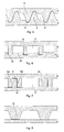
- Figures 3 to 5 illustrate different ridge profile geometries according to the above-mentioned embodiments of the invention.
- Fig. 3 shows the same geometry as Fig. 1 , i.e. both walls having the same profile of trapezoidal ridges 6, 8, each ridge 6 engaging the sides of two adjacent ridges 8 on the opposite wall.
- a connection between the contacting sides 6a and 8a may be achieved by pressing the walls 2 and 4 together to achieve either a frictional engagement between the opposing ridges, or even a friction welded connection.
- the pressure may be exerted by passing the folded tube between two suitably adjusted rolls.
- the connection may be achieved by brazing which will be described in more detail below.
- Fig. 4 and 5 display ridge geometries in which two ridges 16, 18 on the first and second walls only engage each other on one side, while a refrigerant passage 10 is formed on the other side.
- This design allows for a larger cross-section of the fluid passages 10.
- Each ridge 16, 18 engages a corresponding recess 19 in the opposing wall.
- This embodiment may be designed either with trapezoidal ridges as in Fig. 4 or with ridges having rounded edges as in Fig. 5 .
- FIG. 6 A variant not covered by the invention is shown in Fig. 6 using rectangular ridge profiles, but it may be embodied with trapezoidal profiles, too.
- the embodiment of Fig. 6 uses different profiles for upper and lower walls. Therefore, it might be preferable to construct a fluid tube with this design from two separate sheets rather than from one sheet folded at midpoint. The sheets could be rolled with the same roll but at different reductions.
- the upper wall has relatively high ridges 26, each engaging a shallow groove 30 formed between a couple of low ridges 28 on the lower wall.
- FIG. 7 A further variant is shown in Fig. 7 .
- a rectangular or otherwise shaped ridge 38 on the lower wall 4 engages a groove 37 formed between a couple of ridges 36a, 36b, formed in the upper wall 2.
- the ridges 36a, 36b reach as far as the lower wall and a refrigerant passage 10 is formed on the outer sides of ridges 36a, 36b. Since the contact surface 39 between ridges 36 and 38 is particularly large in this embodiment, the strength of the connection between upper and lower walls is excellent.
- Fig. 9a and 9b The variant shown in Fig. 9a and 9b is particularly suited for a frictional or friction welded connection between the upper and lower wall achieved by rolling.
- Fig. 9a shows the profile before rolling
- Fig. 9b shows the profile after rolling.
- the upper wall 2 is provided with main ridges 46 each having a flat top structured in small ridges 47 and engaging the flat inner surface of the lower wall 4.
- main ridges 46 each having a flat top structured in small ridges 47 and engaging the flat inner surface of the lower wall 4.
- the small ridges 47 are pressed into the inner surface of the lower wall and thus form corresponding small ridges 48 in the lower wall.
- This connection may either be the only connection of the tube, or may be combined with brazing.
- FIG. 8 A variant of the above variant is shown in Fig. 8 .
- trapezoidal ridges 46 on the upper wall engage the flat inner surface of the lower wall 4.
- All embodiments of the profiles may be produced by rolling a metal sheet or plate, preferably an aluminium alloy sheet.
- the sheet may either be blank, or may be clad on one or both sides with a brazing filler material.
- the clad layer will preferably have a thickness of 2 to 13% of the total thickness of the brazing sheet.
- the choice of brazing material will depend on the chosen method of "preliminary" connection of the tube walls, and on the selected brazing technique, as described below. To achieve a brazing connection between upper and lower walls, one may use a double clad sheet for one wall and a single clad sheet for the other.
- the length g was 2 mm.
- a photograph of the left profile is shown in Fig. 11 .
- This roll was used to roll an aluminium brazing sheet having a 5 % clad layer of brazing material.
- the aluminium core was made of an AA3003 aluminium alloy according to the classification of the Aluminium Association, and the clad layer was made of an AA4004 aluminium alloy.
- the result is shown in Fig. 12 .
- the roll produced an almost perfect trapezoidal profile of ridges.
- the clad layer accumulated mainly on the top of the ridges and the bottom of the grooves.
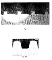
- FIG. 13 and 14 Another example of a brazing sheet rolled with the rough profile depicted on the left of Fig. 10 and the fine profile depicted on the right of Fig. 10 is shown in Fig. 13 and 14 , respectively.
- the "s" stands for side and "c” stands for centre.
- This brazing sheet had a core of AA3003-type alloy and a 10 % clad layer of an AA4045 aluminium alloy.
- the roll produced a very regular shape of trapezoidal ridges, with the best results achieved in the centre of the roll.
- the profile at the sides of the roll was also good.
- FIG. 15 A schematic cross-sectional of a tube made from a rolled brazing sheet product is shown in Fig. 15 before ( Fig. 15a ) and after brazing ( Fig. 15b ) .
- the clad layer 24 is pressed mainly to the top of the ridges and the bottom of the grooves during rolling.
- the molten filler metal flows into the gaps between the ridges 6 and 8 and thereby forms fillets 25 at the contact points of the opposing ridges.
- brazing technique may be used to braze the above-described tubes and the heat exchangers comprising such tubes.
- Nocolok ® registered trademark
- spraying the heat exchanger with flux before brazing is a laborious and therefore expensive process.
- the Nocolok ® process poses the problem of getting the flux inside the tubes. It is therefore more preferred to use one of the following fluxless brazing techniques.
- the parts to be brazed contain sufficient quantities of Mg as known in the art, such that, when heated in a brazing furnace under vacuum conditions, the Mg becomes sufficiently volatile to disrupt the oxide layer and permit the underlying aluminium filler metal to flow together.
- This brazing technique is especially suitable for the present invention, since Mg will accumulate inside the tube and will thus cause a better brazing result.
- the Mg content of the inner clad layer is preferably 0.2 to 1 %, for example 0.6 %.
- Nickel reacts exothermally with the underlying aluminium alloy, thereby disrupting the oxide layer and permitting the filler metal to flow together and join.
- Ni, Co or Fe or alloys thereof may be used, for example as known from US-6,379,818 and US-6,391,476 .
- polymer based brazing techniques uses an additional polymer layer on top of the clad layer containing particles of flux material.
- the polymer layer acts as an adhesive layer to the clad layer.
- the polymer will evaporate in the heat-up cycle during brazing, leaving only the flux material on the metal surface, for example as known from US-6,753,094 .
Abstract
Description
- The invention relates to a tube made of a profile rolled metal product, in particular for use in heat exchangers, a rolled metal product and a method for producing the same. In particular, the invention is directed to a tube including a plurality of reinforcing structures forming longitudinal passages for transporting fluid, e.g. a refrigerant, between them.
- Heat exchanges such as condensers, evaporators and the like for use in car coolers, air conditioning systems etc. usually comprise a number of heat exchange tubes arranged in parallel between two headers, each tube joined at either end to one of the headers. Corrugated fins are disposed in an airflow clearance between adjacent heat exchange tubes and are brazed to the respective tubes. The heat exchanger is typically made of aluminium or an aluminium alloy.
- In the past, flat refrigerant tubes have been manufactured by folding a brazing sheet clad on the outside with a brazing material layer. The refrigerant tubes, the headers and the fins, were then assembled and heated to the brazing temperature at which the clad layer melts and joins together the fins, refrigerant tubes and headers into a brazed assembly.
- It is envisaged gases such as carbon dioxide will be used as cooling medium in air-conditioning systems. The use of carbon dioxide will lead to an increase in operating temperature and pressure of the air-conditioning units. The above-described conventional brazed tubes might not withstand under all circumstances the encountered operating pressures and temperatures. For the existing carbon dioxide based prototypes, the heat exchange tubes have therefore been made of a hollow extrusion comprising flat upper and lower walls and a number of reinforcing walls connecting the upper and lower walls. A disadvantage of the extrusion technique is that the walls cannot be made as thin as desired. Further, an extruded tube cannot be clad with brazing material, so the corrugated fins must be clad in order to allow brazing to the heat exchange tubes, which is expensive due to the large surface area of the fins. In addition, a tube made of brazed sheet or plate is stronger and more resistant against corrosion than extruded tubes.
- The abstract of
JP 2000 074586 A -
US-5,931,226 discloses a refrigerant tube or fluid tube for use in heat exchangers comprising a flat tube having upper and lower walls and a plurality of longitudinal reinforcing walls connected between the upper and lower walls. The reinforcing walls consist of ridges projecting inward from the upper or lower wall and are joined to the flat inner surface of the other wall. The ridges are produced by rolling an aluminium sheet clad with a brazing filler metal layer over at least one of its opposite surfaces with a roll having parallel annular grooves. Parallel refrigerant or fluid passages are defined between adjacent reinforcing walls. Further, the reinforcing walls include a plurality of communication holes for causing the parallel refrigerant passages to communicate with one another. In another embodiment, each reinforcing wall is formed by a ridge projecting from the upper wall and a ridge protecting from the lower wall, joined to each other at their respective top ends. The upper and lower walls are either produced separately or in one sheet, whereby the flat refrigerant tube is manufactured by folding the sheet longitudinally at its midpoint like a hairpin. -
US-5,947,365 describes a process for producing a similar flat heat exchange tube having a plurality of reinforcing walls formed of ridges projecting from the lower wall. The upper and lower walls are connected by brazing the tops of the ridges on the lower wall to the upper wall. In order to strengthen the brazed connection between the reinforcing walls and the lower surface of the upper wall and to prevent the creation of a clearance space there between, the lower surface of the upper wall is provided with smaller longitudinal ridges with which the upper surfaces of the reinforcing walls come into contact to eliminate the clearances and thereby to insure the existence of a continuous brazed connection between each reinforcing wall and lower surface of the upper wall. - A different method of producing reinforcing walls in a flat refrigerant tube for use in heat exchangers is shown in
US-5,186,250 . The tube comprises one or more curved lugs integral with and protruding inwardly from an inner surface of each plane wall, and the curved lugs respectively have innermost tops so that the innermost tops protruding from one plane wall bear against the inner surface of the other plane wall or against the tops of the other curved lugs protruding from the opposite plane wall. The purpose of such protruding lugs is said to improve the pressure resistance of the tube while minimizing its height and thickness. - In the production of these known tubes, it is difficult to achieve a precise alignment between the ridges on the upper and lower walls, especially in those embodiments where two ridges protruding from opposing walls have to be joined head-on. Further, the brazed connection between the ridges or between the top of a ridge and the lower surface of the opposing wall is not very strong.
- It is an object of the present invention to provide a tube made of a profile rolled metal product, in particular for use in heat exchangers, made of a profile rolled metal product, the tube comprising a first wall and a second wall forming two opposing walls of said tube, and a plurality of reinforcing structures connecting the first and second walls and forming longitudinal passages for transporting fluid between the first and the second wall, and having an improved strength and pressure resistance. It is further an object of the invention to provide a relative simple method of producing such a profile rolled tube.
- The invention meets one or more of these objects by providing a tube made of a profile rolled metal product according to the independent claims. Preferred embodiments are described and specified by this specification.
- As will be appreciated herein below, except otherwise indicated, all alloy designations and temper designations refer to the Aluminium Association designations in Aluminium Standards and Data and the Registration Records, as published by the Aluminium Association.
- According to
claim 1, a tube made of a profile rolled metal product, in particular for use in heat exchangers includes a first wall and a second wall forming two opposing sides of the tube, and a plurality of reinforcing structures connecting the first and the second walls and forming longitudinal passages for transporting fluid (also referred to as fluid passages) between them. Each reinforcing structure compromises a longitudinal ridge on the first wall projecting towards the second wall and a longitudinal ridge on the second wall projecting towards the first wall, the ridges engaging each other at theirs sides. The sideways engagement of the ridges has one or more of the following advantages. First, it gives a more stable and pressure resistant junction between the first and the second wall because the areas joined together may be made relatively large. Further, the joint is subjected to shear forces rather than traction forces when the pressure inside the tube increases. In addition, the positioning of the first and second walls on top of each other is facilitated if the ridges engage each other's sideways. Hence, the ridges might serve as a positioning aid directing the walls to the desired position with respect to one another. - There are several preferred embodiments of the profile geometry of the first and second walls. The ridges disposed on the first and second walls are broader at the base than at the top, though most embodiments will work with a a cone-shaped profile too. At present, a trapezoidal cross-section is most preferred.
- In a preferred embodiment, the first wall has the same profile, i.e. the same ridge geometry as the second wall. This has the additional advantage that the fluid tube may be produced by folding a single sheet.
- It has been found advantageous to provide the ridges with cut-outs forming communication holes or passages for causing adjacent fluid passages to communicate with one another. Thus, the ridges are not continuous over the entire length of a tube, but have gaps spaced from one another, forming the holes. Such holes are believed to cause turbulence in the refrigerant flow and thus promote the heat exchange between the tube walls and the refrigerant flowing through the tube.
- Both walls have a profile of ridges which are broader at the base than at the top and spaced from one another such that a groove is formed between two neighbouring ridges. In a preferred embodiment, the two sides of a ridge engage the two sides of a groove in the opposing wall, thereby forming a longitudinal passage in the groove. This embodiment has particularly high strength, because each ridge may be connected to another ridge on either side. When assembling the two walls, the ridges on either wall will interdigitate and thereby exactly fit into one another. Therefore, this design is particularly easy to assemble. The same applies for the cone-shaped profiles mutatis mutandis.
- According to the second embodiment, each ridge on one wall is joined to a ridge on the opposing wall on one side, forming a refrigerant passage on its other side. This profile will leave more open space between the ridges. The top of each ridge in one wall engages a recess in the other wall and the two walls form fit with each other. When assembling the tube, the two walls will effectively click into each other.
- The ridges of the first and second walls are preferably joined to each other by one or more of friction welding, resistance welding or brazing, or by a combination of welding and brazing.
- In a further aspect of the invention it provides a rolled metal product for producing the first and/or the second wall of the above-described tubes. Thus, the rolled metal product has a profile as described above and is produced by rolling a brazing sheet clad at least on one side with a brazing material.
- In another aspect of the invention there is provided a method for producing a tube according to this invention, the method comprising the steps of:
- producing the first and the second wall by rolling a metal sheet clad at least on one side with a brazing material with a pair of rolls, one of the rolls having parallel annular grooves for forming ridges on one side of the sheet,
- placing the first wall on top of the second wall,
- connecting the first and second walls by clamping or rolling.
- One of the problems encountered in producing heat exchangers using the tube according to the invention is to hold the first and second walls together, while assembling all components of the heat exchanger for subsequent brazing. If the first and second walls are not held together properly, a gap might open at the side or between the opposing ridges, resulting in a leaking tube and rejection of the heat exchanger as a whole. The method therefore provides a preliminary connection of the two walls, which may be achieved by clamping or rolling.
- According to an embodiment, the first and second walls are clamped together by flanging the sides. One edge of a longitudinal wall is for example bent to a U-shape holding the second wall. According to a preferred embodiment, the first and second walls are joined together by rolling. Such rolling may either cause a frictional connection between the first and second walls or a friction weld between the sides of the ridges engaging each other. Such a connection may occur, for example, when the interdigitating trapezoidal ridges of the first embodiment are pressed into one another.
- In another aspect to invention relates to a method of producing a heat exchanger, the heat exchanger comprising a pair of headers, a plurality of refrigerant tubes joined at each end to one of the headers, and corrugated fins disposed between adjacent refrigerant tubes, and the method comprising the steps of
- producing the refrigerant tubes according to the method set out above,
- assembling the headers, the refrigerant tubes, and the corrugated fins,
- brazing the heat exchanger assembly.
- Preferably, the tubes are made from a metal sheet, typically of an aluminium alloy, clad on one or both sides with a brazing material. If the insides of the refrigerant tubes are clad with the brazing material, the sides of the profiled ridges engaging each other are brazed together during brazing of the heat exchanger assembly. The clad layer on the outside serves to braze the corrugated fins to the heat exchanger tubes.
- The above-mentioned and further features and advantages of the invention will become apparent from the following detailed descriptions of preferred embodiments with reference to the appended drawings. The drawings show:
-
Fig. 1 a schematic cross-sectional view of a tube according to a first embodiment of the invention; -
Fig. 2 a schematic perspective view of the lower wall of the embodiment ofFig. 1 ; -
Fig. 3 enlarged schematic cross-sectional view of the profile according to the first embodiment; -
Figs. 4 to 5 enlarged schematic cross-sectional views of profiles according to further embodiments of the invention; -
Figs. 6 to 8 enlarged schematic cross-sectional views of profiles not covered by the invention; -
Fig. 9 a and b an enlarged schematic sectional view of a ridge profile not covered by the invention before (Fig. 9a ) and after (Fig. 9b ) rolling of the tubes; -
Fig. 10 side view of a profile formed roll used to produce the profiled brazing sheets of the examples; -
Fig. 11 an enlarged photograph of the roll surface; -
Fig. 12 an enlarged cut image of a brazing sheet after rolling according to the first embodiment; -
Fig. 13 polished cut images of a brazing sheet after rolling according to the second embodiment; -
Fig. 14 enlarged cut images of rolled brazing sheets according to the third embodiment; and -
Fig. 15 a and b an enlarged cross-sectional view of a profile according to the first embodiment before (Fig. 15a ) and after brazing (Fig. 15b ). - A schematic cross-sectional view of a refrigerant tube according to a first embodiment of the invention is shown in
Fig. 1 . The tube is substantially flat and having a width w of up to 100 mm and typically about 15 to 50 mm, and a height h of up to 10 mm and typically about 0.5 to 5 mm. The prior art tubes made of non-profiled aluminium sheets have wall thicknesses of 0.25 to 0.4 mm, but the tube having reinforcing walls according to the invention may have thinner walls while retaining the same stability and pressure resistance, for example a = 0.1 to 0.3 mm, preferably 0.15 to 0.25 mm. The tube is made fromupper wall 2 and lower wall 4 produced by folding a rolled metal sheet longitudinally like a hairpin. The fold is indicated at 12. On the other side, upper and lower wall are held together by flange 14, which ends in this example around aledge 15 on the lower wall and thereby produces a mechanical fixation of upper and lower wall with respect to one another. Both upper and lower walls display the same profile oftrapezoidal ridges open spaces 10 as fluid passages. The fluid passages are preferably up to about 0.5 mm high. - The
ridges outs 20 forming communication holes between adjacentfluid passages 10. The arrows inFig. 2 indicate the direction of flow, which is diverted from the leftmost passage to the adjacent passages. The cut-outs 20 may be disposed at the same longitudinal position for eachridge 8, or may be distributed along the length of the tube. In either case, the communication holes provide improved convention or turbulence of the cooling fluid between the different passages and as a resultant more heat transfer. -
Figures 3 to 5 illustrate different ridge profile geometries according to the above-mentioned embodiments of the invention.Fig. 3 shows the same geometry asFig. 1 , i.e. both walls having the same profile oftrapezoidal ridges ridge 6 engaging the sides of twoadjacent ridges 8 on the opposite wall. A connection between the contactingsides walls 2 and 4 together to achieve either a frictional engagement between the opposing ridges, or even a friction welded connection. The pressure may be exerted by passing the folded tube between two suitably adjusted rolls. In addition, the connection may be achieved by brazing which will be described in more detail below. -
Fig. 4 and5 display ridge geometries in which tworidges refrigerant passage 10 is formed on the other side. This design allows for a larger cross-section of thefluid passages 10. Eachridge corresponding recess 19 in the opposing wall. This embodiment may be designed either with trapezoidal ridges as inFig. 4 or with ridges having rounded edges as inFig. 5 . - A variant not covered by the invention is shown in
Fig. 6 using rectangular ridge profiles, but it may be embodied with trapezoidal profiles, too. The embodiment ofFig. 6 uses different profiles for upper and lower walls. Therefore, it might be preferable to construct a fluid tube with this design from two separate sheets rather than from one sheet folded at midpoint. The sheets could be rolled with the same roll but at different reductions. In detail, the upper wall has relativelyhigh ridges 26, each engaging ashallow groove 30 formed between a couple oflow ridges 28 on the lower wall. - A further variant is shown in
Fig. 7 . In this design, a rectangular or otherwise shapedridge 38 on the lower wall 4 engages agroove 37 formed between a couple ofridges upper wall 2. In contrast toFig. 6 , theridges refrigerant passage 10 is formed on the outer sides ofridges contact surface 39 betweenridges 36 and 38 is particularly large in this embodiment, the strength of the connection between upper and lower walls is excellent. - The variant shown in
Fig. 9a and 9b is particularly suited for a frictional or friction welded connection between the upper and lower wall achieved by rolling.Fig. 9a shows the profile before rolling, andFig. 9b shows the profile after rolling. As shown inFig. 9a , theupper wall 2 is provided withmain ridges 46 each having a flat top structured insmall ridges 47 and engaging the flat inner surface of the lower wall 4. When upper and lower walls are pressed together by rolling, thesmall ridges 47 are pressed into the inner surface of the lower wall and thus form correspondingsmall ridges 48 in the lower wall. This will result in a frictional connection or a friction welded connection between upper and lower walls. This connection may either be the only connection of the tube, or may be combined with brazing. - A variant of the above variant is shown in
Fig. 8 . In this design,trapezoidal ridges 46 on the upper wall engage the flat inner surface of the lower wall 4. - All embodiments of the profiles may be produced by rolling a metal sheet or plate, preferably an aluminium alloy sheet. The sheet may either be blank, or may be clad on one or both sides with a brazing filler material. The clad layer will preferably have a thickness of 2 to 13% of the total thickness of the brazing sheet. The choice of brazing material will depend on the chosen method of "preliminary" connection of the tube walls, and on the selected brazing technique, as described below. To achieve a brazing connection between upper and lower walls, one may use a double clad sheet for one wall and a single clad sheet for the other.
- Representative examples of the above-shown profiles have been produced with the profile formed roll shown in
Fig. 10 . The length L was 405 mm, the diameter D was 79.66 mm, and the lengths L1 to L4 of the roll profile were 15 mm, 20.4 mm, 20.8 mm and 15 mm, respectively. The sections L2 and L3 of the roll are provided with 18 and 28 parallel annular grooves, respectively, the detailed profiles of which are shown in the lower part of the drawing. - The left profile consisted of trapezoidal grooves of depth b = 0.8 mm, width at base f = 0.55 mm and width at top e = 0.85 mm. The sides were tilted at an angle of α = 11.8 ° with respect to the vertical. The distance between adjacent grooves was c = 0.3 mm at the top and d = 0.6 mm at the bottom.
- The smaller profile shown on the right had grooves of a depth b = 0.5 mm. The sides of the grooves were tilted α = 12.5 ° with respect to the vertical, and the grooves had a bottom width of f = 0.35 mm and top width e = 0.55 mm. The distance between adjacent grooves was c = 0.2 mm at the top and d = 0.4 mm at the bottom. The length g was 2 mm. A photograph of the left profile is shown in
Fig. 11 . - This roll was used to roll an aluminium brazing sheet having a 5 % clad layer of brazing material. The aluminium core was made of an AA3003 aluminium alloy according to the classification of the Aluminium Association, and the clad layer was made of an AA4004 aluminium alloy. The result is shown in
Fig. 12 . As is apparent from the figure, the roll produced an almost perfect trapezoidal profile of ridges. The clad layer accumulated mainly on the top of the ridges and the bottom of the grooves. - Another example of a brazing sheet rolled with the rough profile depicted on the left of
Fig. 10 and the fine profile depicted on the right ofFig. 10 is shown inFig. 13 and 14 , respectively. InFigs. 13 and 14 the "s" stands for side and "c" stands for centre. This brazing sheet had a core of AA3003-type alloy and a 10 % clad layer of an AA4045 aluminium alloy. Again, the roll produced a very regular shape of trapezoidal ridges, with the best results achieved in the centre of the roll. However, the profile at the sides of the roll was also good. - A schematic cross-sectional of a tube made from a rolled brazing sheet product is shown in
Fig. 15 before (Fig. 15a ) and after brazing (Fig. 15b ) . As shown by the examples, the cladlayer 24 is pressed mainly to the top of the ridges and the bottom of the grooves during rolling. During brazing, the molten filler metal flows into the gaps between theridges fillets 25 at the contact points of the opposing ridges. - In principle all kinds of brazing technique may be used to braze the above-described tubes and the heat exchangers comprising such tubes.
- One of the preferred techniques for brazing aluminium heat exchangers utilizes Nocolok® (registered trademark) flux. Nocolok® may be used with the present invention, too. However, spraying the heat exchanger with flux before brazing is a laborious and therefore expensive process. In case the profiles of the refrigerant tubes are to be brazed together, the Nocolok® process poses the problem of getting the flux inside the tubes. It is therefore more preferred to use one of the following fluxless brazing techniques.
- In vacuum brazing, the parts to be brazed contain sufficient quantities of Mg as known in the art, such that, when heated in a brazing furnace under vacuum conditions, the Mg becomes sufficiently volatile to disrupt the oxide layer and permit the underlying aluminium filler metal to flow together. This brazing technique is especially suitable for the present invention, since Mg will accumulate inside the tube and will thus cause a better brazing result. The Mg content of the inner clad layer is preferably 0.2 to 1 %, for example 0.6 %.
- Another fluxless brazing technique uses a thin nickel layer on top of the clad layer. Nickel reacts exothermally with the underlying aluminium alloy, thereby disrupting the oxide layer and permitting the filler metal to flow together and join. Instead of Ni, Co or Fe or alloys thereof may be used, for example as known from
US-6,379,818 andUS-6,391,476 . - It is further contemplated to use polymer based brazing techniques. This method uses an additional polymer layer on top of the clad layer containing particles of flux material. The polymer layer acts as an adhesive layer to the clad layer. The polymer will evaporate in the heat-up cycle during brazing, leaving only the flux material on the metal surface, for example as known from
US-6,753,094 . - Having now fully described the invention, it will be apparent to one of ordinary skill in the art that many changes and modifications can be made without departing from the scope of the invention as hereon described.
Claims (15)
- A tube (1) made of a profile rolled metal product, in particular for use in heat exchangers, the tube comprising a first wall (2) and a second wall (4) forming two opposing walls of said tube, and a plurality of reinforcing structures connecting the first and second walls and forming longitudinal passages (10) for transporting fluid between the first and the second wall, and wherein each reinforcing structure comprises a longitudinal ridge (6,16,26,36) on the first wall projecting towards the second wall, and a longitudinal ridge (8,18,28) on the second wall projecting towards the first wall, the ridges engaging each other at their sides (6a,8a), and the ridges on the first and the second walls have a profile selected from the group comprising a trapezoldal and a cone-shaped profile, wherein the ridges on the first and the second walls are broader at the base than at the top, wherein each wall has a profile of ridges (6,8) spaced from each other such that a groove is formed between two neighbouring ridges, characterized in that the two sides (6a) of a ridge engage the two sides (8a) of a groove in the opposing wall, thereby forming a longitudinal passage (10) in the groove.
- A tube (1 ) made of a profile rolled metal product, in particular for use in heat exchangers, the tube comprising a first wall (2) and a second wall (4) forming two opposing walls of said tube, and a plurality of reinforcing structures connecting the first and second walls and forming longitudinal passages (10) for transporting fluid between the first and the second wall, and wherein each reinforcing structure comprises a longitudinal ridge (16) on the first wall projecting towards the second wall, and a longitudinal ridge (18) on the second wall projecting towards the first wall, the ridges engaging each other at their sides, and the ridges (16, 18) on the first and the second walls have a profile selected from the group comprising a trapezoidal and a cone-shaped profile, wherein the ridges on the first and the second walls are broader at the base than at the top, wherein each wall has a profile of ridges (16, 18) spaced from each other such that a groove is formed between two neighbouring ridges, wherein each ridge (16) engages a ridge (18) on the opposing wall on one side, forming a fluid passage on its other side, characterized in that the top of each ridge (16,18) in one wall engages a recess (19) formed in the other wall.
- A tube according to claim 1 or 2, wherein the first wall (2) has the same ridge profile as the second wall (4).
- A tube according to any one of claims 1 to 3, wherein each ridge on the first and/or second wall includes a plurality of cut-outs (20) forming communication holes for causing neighbouring longitudinal passages (10) to communicate with one another.
- A tube according to any one of claims 1 to 4, wherein the ridges on the first and second walls are joined to each other by one or more of friction welding, resistance welding, or brazing.
- A tube according to any one of claims 1 to 5, wherein the profile rolled metal product is made from a brazing sheet product comprising an aluminium alloy on one or both sides clad with a brazing filler material.
- A tube according to any one of claims 1 to 6, wherein the first wall (2) and the second wall (4) are joined to each other by means of brazing.
- A rolled metal product for producing the first and/or second wall (2,4) of the tube according to any one of claim 1 to 7, wherein it has a profile as described in claim 1 or claim 2 and is produced by rolling a brazing sheet clad at least on one side with a brazing material.
- A method for producing a tube according to any one of claims 1 or 3 to 7, comprising the steps of- producing the first and the second wall by rolling a metal sheet clad at least on one side with a brazing material with a pair of rolls, one of the rolls having parallel annular grooves for forming ridges on one side of the sheet, wherein the ridges on the first and the second walls are broader at the base than at the top, and wherein each wall has a profile of ridges (6,8) spaced from each other such that a groove is formed between two neighbouring ridges- placing the first wall (2) on top of the second wall (4),- connecting the first and second walls by clamping or rolling, wherein the two sides (6a) of a ridge engage the two sides (8a) of a groove in the opposing wall, thereby forming a longitudinal passage (10) in the groove.
- A method for producing a tube according to any one of claims 2 - 7, comprising the steps of- producing the first and the second wall by rolling a metal sheet clad at least on one side with a brazing material with a pair of rolls, one of the rolls having parallel annular grooves for forming ridges on one side of the sheet, wherein the ridges on the first and the second walls are broader at the base than at the top, wherein each wall has a profile of ridges (16, 18) spaced from each other such that a groove is formed between two neighbouring ridges,- placing the first wall (2) on top of the second wall (4),- connecting the first and second walls by clamping or rolling, wherein each ridge (16) engages a ridge (18) on the opposing wall on one side, forming a fluid passage on its other side, and wherein the top of each ridge (16,18) in one wall engages a recess (19) formed in the other wall.
- The method according to claim 9 or 10, wherein the first and second walls are clamped together by forming a flange (14) on one of the walls holding the other wall.
- The method according to claim 9, 10 or 11, wherein the first and second walls are joined together by rolling, thereby causing a frictional connection and/or a friction welded connection between the sides (6a,8a) of the ridges engaging each other.
- A method for producing a heat exchanger comprising a pair of headers, a plurality of refrigerant tubes joined at each end to one of the headers, and corrugated fins disposed between adjacent refrigerant tubes, comprising the steps of- producing the refrigerant tubes according to the method of any one of claim 9 to 12.- assembling the headers, the refrigerant tubes, and the corrugated fins,- brazing the heat exchanger assembly.
- The method of claim 13, wherein the tubes are made from a aluminium sheet clad on at least the profiled side with a brazing material, and the first and second walls are brazed together during brazing of the heat exchanger assembly.
- The method according to claim 14, wherein brazing the heat exchanger assembly is by means of vacuum brazing or by fluxless brazing.
Priority Applications (1)
| Application Number | Priority Date | Filing Date | Title |
|---|---|---|---|
| EP05794807A EP1802932B1 (en) | 2004-10-22 | 2005-10-04 | Tube made of a profile rolled metal product and method of producing the same |
Applications Claiming Priority (3)
| Application Number | Priority Date | Filing Date | Title |
|---|---|---|---|
| EP04077907 | 2004-10-22 | ||
| PCT/EP2005/010807 WO2006045415A1 (en) | 2004-10-22 | 2005-10-04 | Tube made of a profile rolled metal product and method of producing the same |
| EP05794807A EP1802932B1 (en) | 2004-10-22 | 2005-10-04 | Tube made of a profile rolled metal product and method of producing the same |
Publications (2)
| Publication Number | Publication Date |
|---|---|
| EP1802932A1 EP1802932A1 (en) | 2007-07-04 |
| EP1802932B1 true EP1802932B1 (en) | 2009-06-03 |
Family
ID=34928589
Family Applications (1)
| Application Number | Title | Priority Date | Filing Date |
|---|---|---|---|
| EP05794807A Not-in-force EP1802932B1 (en) | 2004-10-22 | 2005-10-04 | Tube made of a profile rolled metal product and method of producing the same |
Country Status (10)
| Country | Link |
|---|---|
| US (1) | US7690114B2 (en) |
| EP (1) | EP1802932B1 (en) |
| JP (1) | JP4926972B2 (en) |
| KR (1) | KR101181615B1 (en) |
| CN (1) | CN101065633B (en) |
| AT (1) | ATE433087T1 (en) |
| CA (1) | CA2591683C (en) |
| DE (2) | DE602005014796D1 (en) |
| FR (1) | FR2878946B1 (en) |
| WO (1) | WO2006045415A1 (en) |
Families Citing this family (8)
| Publication number | Priority date | Publication date | Assignee | Title |
|---|---|---|---|---|
| DE102008051894A1 (en) | 2008-10-16 | 2010-05-06 | Behr Gmbh & Co. Kg | Metal load-adapted structural part for a heat exchanger, method for producing a load-adapted structural part, heat exchangers |
| CN101832726B (en) * | 2009-03-11 | 2012-01-25 | 三花丹佛斯(杭州)微通道换热器有限公司 | Heat radiating pipe for heat exchanger and manufacturing method thereof |
| US8174288B2 (en) * | 2009-04-13 | 2012-05-08 | International Business Machines Corporation | Voltage conversion and integrated circuits with stacked voltage domains |
| US20150026981A1 (en) * | 2013-07-24 | 2015-01-29 | Asia Vital Components Co., Ltd. | Manufacturing mehtod of vapor chamber structure |
| DE102014002829A1 (en) * | 2014-02-27 | 2015-08-27 | Wieland-Werke Ag | Metallic heat exchanger tube |
| CN113020264A (en) * | 2021-03-25 | 2021-06-25 | 太原理工大学 | Metal composite plate rolling method for forming interweaving combination interface |
| CN113231469B (en) * | 2021-05-10 | 2023-04-18 | 贵州大学 | Method for hot rolling of aluminum alloy material sheath for zinc-based composite material |
| CN116871837A (en) * | 2023-09-04 | 2023-10-13 | 中山莱通金属科技有限公司 | Micro-channel porous flat tube process for low-cost parallel flow radiator |
Family Cites Families (17)
| Publication number | Priority date | Publication date | Assignee | Title |
|---|---|---|---|---|
| JPS5671520A (en) * | 1979-11-13 | 1981-06-15 | Nissan Motor Co Ltd | Production of tube structural body |
| US5186250A (en) | 1990-05-11 | 1993-02-16 | Showa Aluminum Kabushiki Kaisha | Tube for heat exchangers and a method for manufacturing the tube |
| US5931226A (en) | 1993-03-26 | 1999-08-03 | Showa Aluminum Corporation | Refrigerant tubes for heat exchangers |
| AU5501896A (en) | 1995-04-26 | 1996-11-18 | Helmut Lingemann Gmbh & Co | Flat tube with multiple cavities for heat exchangers and pro cess for manufacturing the same |
| DE19518657A1 (en) * | 1995-04-26 | 1996-10-31 | Lingemann Helmut Gmbh & Co | Multi-chamber flat tube for heat exchangers and process for its manufacture |
| DE69730881T2 (en) | 1996-06-26 | 2005-09-22 | Showa Denko K.K. | Process for the production of flat tubes for heat exchangers |
| JP3947830B2 (en) * | 1996-06-26 | 2007-07-25 | 昭和電工株式会社 | Manufacturing method of flat heat exchange tube |
| US5937517A (en) * | 1997-11-12 | 1999-08-17 | Eastman Kodak Company | Method of manufacturing bonded dual extruded, high fin density heat sinks |
| JP2000074586A (en) | 1998-08-31 | 2000-03-14 | Toyo Radiator Co Ltd | Flat tube for heat exchanger |
| US6753094B1 (en) | 1999-04-22 | 2004-06-22 | Corus Aluminium Walzprodukte Gmbh | Composite sheet material for brazing |
| BR0010818B1 (en) | 1999-05-21 | 2010-06-15 | welding plate product and process for its preparation. | |
| JP2000346576A (en) | 1999-05-31 | 2000-12-15 | Mitsubishi Heavy Ind Ltd | Heat exchanger and method of manufacturing the same |
| US6209202B1 (en) * | 1999-08-02 | 2001-04-03 | Visteon Global Technologies, Inc. | Folded tube for a heat exchanger and method of making same |
| ATE367238T1 (en) | 2000-03-10 | 2007-08-15 | Aleris Aluminum Koblenz Gmbh | BRAZED SHEET AND METHOD OF MAKING AN ASSEMBLY USING THIS PRODUCT |
| JP4536273B2 (en) | 2001-01-31 | 2010-09-01 | 株式会社ティラド | Flat tube for heat exchanger and method of manufacturing heat exchanger |
| JP3951812B2 (en) * | 2001-06-08 | 2007-08-01 | 昭和電工株式会社 | Metal plate for flat tube manufacturing, flat tube and flat tube manufacturing method |
| ATE402769T1 (en) | 2001-06-08 | 2008-08-15 | Showa Denko Kk | METAL PLATE FOR PRODUCING A FLAT TUBE |
-
2005
- 2005-10-04 JP JP2007537150A patent/JP4926972B2/en not_active Expired - Fee Related
- 2005-10-04 AT AT05794807T patent/ATE433087T1/en not_active IP Right Cessation
- 2005-10-04 DE DE602005014796T patent/DE602005014796D1/en active Active
- 2005-10-04 CA CA2591683A patent/CA2591683C/en not_active Expired - Fee Related
- 2005-10-04 CN CN2005800354626A patent/CN101065633B/en not_active Expired - Fee Related
- 2005-10-04 US US11/242,124 patent/US7690114B2/en not_active Expired - Fee Related
- 2005-10-04 KR KR1020077011331A patent/KR101181615B1/en active IP Right Grant
- 2005-10-04 EP EP05794807A patent/EP1802932B1/en not_active Not-in-force
- 2005-10-04 WO PCT/EP2005/010807 patent/WO2006045415A1/en active Application Filing
- 2005-10-10 DE DE102005048407A patent/DE102005048407A1/en not_active Ceased
- 2005-10-17 FR FR0510544A patent/FR2878946B1/en not_active Expired - Fee Related
Also Published As
| Publication number | Publication date |
|---|---|
| JP4926972B2 (en) | 2012-05-09 |
| US20060112557A1 (en) | 2006-06-01 |
| CN101065633B (en) | 2011-05-25 |
| KR20070074627A (en) | 2007-07-12 |
| KR101181615B1 (en) | 2012-09-10 |
| JP2008516778A (en) | 2008-05-22 |
| CN101065633A (en) | 2007-10-31 |
| EP1802932A1 (en) | 2007-07-04 |
| CA2591683A1 (en) | 2006-05-04 |
| US7690114B2 (en) | 2010-04-06 |
| FR2878946A1 (en) | 2006-06-09 |
| CA2591683C (en) | 2013-12-10 |
| WO2006045415A1 (en) | 2006-05-04 |
| FR2878946B1 (en) | 2010-08-20 |
| DE102005048407A1 (en) | 2006-07-27 |
| DE602005014796D1 (en) | 2009-07-16 |
| ATE433087T1 (en) | 2009-06-15 |
Similar Documents
| Publication | Publication Date | Title |
|---|---|---|
| EP1802932B1 (en) | Tube made of a profile rolled metal product and method of producing the same | |
| US5185925A (en) | Method of manufacturing a tube for a heat exchanger | |
| US7749609B2 (en) | Metal plate for producing flat tube, flat tube and process for producing the flat tube | |
| AU722225B2 (en) | Process for producing flat heat exchange tubes | |
| EP0881449A2 (en) | Refrigerant tubes for heat exchangers | |
| US9593889B2 (en) | Heat exchanger construction | |
| JP2007139417A (en) | Metal plate for producing flat tube, flat tube, and its manufacturing method | |
| US20020057941A1 (en) | Connection structure between a pipe and a tube for use in a heat exchanger | |
| JP2004167601A (en) | Semiprocessed flat tube and its manufacturing method, flat tube, heat-exchanger using flat tube and its manufacturing method | |
| JP2000193387A5 (en) | ||
| EP1027942A1 (en) | Tube for heat exchanger and method of manufacturing same | |
| JP2007107754A (en) | Heat exchanger and its manufacturing method | |
| US5881457A (en) | Method of making refrigerant tubes for heat exchangers | |
| JP3095878B2 (en) | Heat exchanger | |
| US20020007940A1 (en) | Brazed tube for a heat exchanger, method of manufacture and exchanger | |
| JP4506435B2 (en) | Heat exchanger | |
| EP4065914B1 (en) | Flat heat exchanger tube | |
| AU2003274739A1 (en) | Semifinished flat tube, process for producing same, flat tube, heat exchanger comprising the flat tube and process for fabricating the heat exchanger | |
| US20050045315A1 (en) | Concentric tube heat exchanger and end seal therefor | |
| JPH0593592A (en) | Heat exchanger | |
| JPH0723101Y2 (en) | Brazing jig for aluminum laminated heat exchanger manufacturing | |
| JP3209856B2 (en) | Manufacturing method of heat exchanger made of aluminum material | |
| JPH09243290A (en) | Heat exchanger made of aluminum alloy | |
| JPH05228620A (en) | Manufacture of heat exchanger made of aluminum | |
| JP2006112651A (en) | Heat exchanger |
Legal Events
| Date | Code | Title | Description |
|---|---|---|---|
| PUAI | Public reference made under article 153(3) epc to a published international application that has entered the european phase |
Free format text: ORIGINAL CODE: 0009012 |
|
| 17P | Request for examination filed |
Effective date: 20070306 |
|
| AK | Designated contracting states |
Kind code of ref document: A1 Designated state(s): AT BE BG CH CY CZ DE DK EE ES FI FR GB GR HU IE IS IT LI LT LU LV MC NL PL PT RO SE SI SK TR |
|
| 17Q | First examination report despatched |
Effective date: 20070731 |
|
| DAX | Request for extension of the european patent (deleted) | ||
| GRAP | Despatch of communication of intention to grant a patent |
Free format text: ORIGINAL CODE: EPIDOSNIGR1 |
|
| GRAS | Grant fee paid |
Free format text: ORIGINAL CODE: EPIDOSNIGR3 |
|
| GRAA | (expected) grant |
Free format text: ORIGINAL CODE: 0009210 |
|
| AK | Designated contracting states |
Kind code of ref document: B1 Designated state(s): AT BE BG CH CY CZ DE DK EE ES FI FR GB GR HU IE IS IT LI LT LU LV MC NL PL PT RO SE SI SK TR |
|
| REG | Reference to a national code |
Ref country code: GB Ref legal event code: FG4D |
|
| REG | Reference to a national code |
Ref country code: CH Ref legal event code: EP |
|
| REG | Reference to a national code |
Ref country code: IE Ref legal event code: FG4D |
|
| REF | Corresponds to: |
Ref document number: 602005014796 Country of ref document: DE Date of ref document: 20090716 Kind code of ref document: P |
|
| PG25 | Lapsed in a contracting state [announced via postgrant information from national office to epo] |
Ref country code: LT Free format text: LAPSE BECAUSE OF FAILURE TO SUBMIT A TRANSLATION OF THE DESCRIPTION OR TO PAY THE FEE WITHIN THE PRESCRIBED TIME-LIMIT Effective date: 20090603 Ref country code: FI Free format text: LAPSE BECAUSE OF FAILURE TO SUBMIT A TRANSLATION OF THE DESCRIPTION OR TO PAY THE FEE WITHIN THE PRESCRIBED TIME-LIMIT Effective date: 20090603 Ref country code: AT Free format text: LAPSE BECAUSE OF FAILURE TO SUBMIT A TRANSLATION OF THE DESCRIPTION OR TO PAY THE FEE WITHIN THE PRESCRIBED TIME-LIMIT Effective date: 20090603 |
|
| NLV1 | Nl: lapsed or annulled due to failure to fulfill the requirements of art. 29p and 29m of the patents act | ||
| PG25 | Lapsed in a contracting state [announced via postgrant information from national office to epo] |
Ref country code: PL Free format text: LAPSE BECAUSE OF FAILURE TO SUBMIT A TRANSLATION OF THE DESCRIPTION OR TO PAY THE FEE WITHIN THE PRESCRIBED TIME-LIMIT Effective date: 20090603 Ref country code: LV Free format text: LAPSE BECAUSE OF FAILURE TO SUBMIT A TRANSLATION OF THE DESCRIPTION OR TO PAY THE FEE WITHIN THE PRESCRIBED TIME-LIMIT Effective date: 20090603 Ref country code: SE Free format text: LAPSE BECAUSE OF FAILURE TO SUBMIT A TRANSLATION OF THE DESCRIPTION OR TO PAY THE FEE WITHIN THE PRESCRIBED TIME-LIMIT Effective date: 20090903 Ref country code: SI Free format text: LAPSE BECAUSE OF FAILURE TO SUBMIT A TRANSLATION OF THE DESCRIPTION OR TO PAY THE FEE WITHIN THE PRESCRIBED TIME-LIMIT Effective date: 20090603 Ref country code: NL Free format text: LAPSE BECAUSE OF FAILURE TO SUBMIT A TRANSLATION OF THE DESCRIPTION OR TO PAY THE FEE WITHIN THE PRESCRIBED TIME-LIMIT Effective date: 20090603 |
|
| PG25 | Lapsed in a contracting state [announced via postgrant information from national office to epo] |
Ref country code: ES Free format text: LAPSE BECAUSE OF FAILURE TO SUBMIT A TRANSLATION OF THE DESCRIPTION OR TO PAY THE FEE WITHIN THE PRESCRIBED TIME-LIMIT Effective date: 20090914 Ref country code: EE Free format text: LAPSE BECAUSE OF FAILURE TO SUBMIT A TRANSLATION OF THE DESCRIPTION OR TO PAY THE FEE WITHIN THE PRESCRIBED TIME-LIMIT Effective date: 20090603 Ref country code: RO Free format text: LAPSE BECAUSE OF FAILURE TO SUBMIT A TRANSLATION OF THE DESCRIPTION OR TO PAY THE FEE WITHIN THE PRESCRIBED TIME-LIMIT Effective date: 20090603 Ref country code: IS Free format text: LAPSE BECAUSE OF FAILURE TO SUBMIT A TRANSLATION OF THE DESCRIPTION OR TO PAY THE FEE WITHIN THE PRESCRIBED TIME-LIMIT Effective date: 20091003 Ref country code: CZ Free format text: LAPSE BECAUSE OF FAILURE TO SUBMIT A TRANSLATION OF THE DESCRIPTION OR TO PAY THE FEE WITHIN THE PRESCRIBED TIME-LIMIT Effective date: 20090603 |
|
| PG25 | Lapsed in a contracting state [announced via postgrant information from national office to epo] |
Ref country code: SK Free format text: LAPSE BECAUSE OF FAILURE TO SUBMIT A TRANSLATION OF THE DESCRIPTION OR TO PAY THE FEE WITHIN THE PRESCRIBED TIME-LIMIT Effective date: 20090603 Ref country code: BE Free format text: LAPSE BECAUSE OF FAILURE TO SUBMIT A TRANSLATION OF THE DESCRIPTION OR TO PAY THE FEE WITHIN THE PRESCRIBED TIME-LIMIT Effective date: 20090603 |
|
| PG25 | Lapsed in a contracting state [announced via postgrant information from national office to epo] |
Ref country code: BG Free format text: LAPSE BECAUSE OF FAILURE TO SUBMIT A TRANSLATION OF THE DESCRIPTION OR TO PAY THE FEE WITHIN THE PRESCRIBED TIME-LIMIT Effective date: 20090903 Ref country code: PT Free format text: LAPSE BECAUSE OF FAILURE TO SUBMIT A TRANSLATION OF THE DESCRIPTION OR TO PAY THE FEE WITHIN THE PRESCRIBED TIME-LIMIT Effective date: 20091003 |
|
| PLBE | No opposition filed within time limit |
Free format text: ORIGINAL CODE: 0009261 |
|
| STAA | Information on the status of an ep patent application or granted ep patent |
Free format text: STATUS: NO OPPOSITION FILED WITHIN TIME LIMIT |
|
| PG25 | Lapsed in a contracting state [announced via postgrant information from national office to epo] |
Ref country code: DK Free format text: LAPSE BECAUSE OF FAILURE TO SUBMIT A TRANSLATION OF THE DESCRIPTION OR TO PAY THE FEE WITHIN THE PRESCRIBED TIME-LIMIT Effective date: 20090603 |
|
| 26N | No opposition filed |
Effective date: 20100304 |
|
| PG25 | Lapsed in a contracting state [announced via postgrant information from national office to epo] |
Ref country code: MC Free format text: LAPSE BECAUSE OF NON-PAYMENT OF DUE FEES Effective date: 20091031 |
|
| REG | Reference to a national code |
Ref country code: CH Ref legal event code: PL |
|
| REG | Reference to a national code |
Ref country code: IE Ref legal event code: MM4A |
|
| REG | Reference to a national code |
Ref country code: FR Ref legal event code: ST Effective date: 20100630 |
|
| PG25 | Lapsed in a contracting state [announced via postgrant information from national office to epo] |
Ref country code: FR Free format text: LAPSE BECAUSE OF NON-PAYMENT OF DUE FEES Effective date: 20091102 |
|
| PG25 | Lapsed in a contracting state [announced via postgrant information from national office to epo] |
Ref country code: CH Free format text: LAPSE BECAUSE OF NON-PAYMENT OF DUE FEES Effective date: 20091031 Ref country code: LI Free format text: LAPSE BECAUSE OF NON-PAYMENT OF DUE FEES Effective date: 20091031 Ref country code: IE Free format text: LAPSE BECAUSE OF NON-PAYMENT OF DUE FEES Effective date: 20091004 Ref country code: GR Free format text: LAPSE BECAUSE OF FAILURE TO SUBMIT A TRANSLATION OF THE DESCRIPTION OR TO PAY THE FEE WITHIN THE PRESCRIBED TIME-LIMIT Effective date: 20090904 |
|
| PG25 | Lapsed in a contracting state [announced via postgrant information from national office to epo] |
Ref country code: GB Free format text: LAPSE BECAUSE OF NON-PAYMENT OF DUE FEES Effective date: 20091004 |
|
| PG25 | Lapsed in a contracting state [announced via postgrant information from national office to epo] |
Ref country code: IT Free format text: LAPSE BECAUSE OF FAILURE TO SUBMIT A TRANSLATION OF THE DESCRIPTION OR TO PAY THE FEE WITHIN THE PRESCRIBED TIME-LIMIT Effective date: 20090603 |
|
| PG25 | Lapsed in a contracting state [announced via postgrant information from national office to epo] |
Ref country code: LU Free format text: LAPSE BECAUSE OF NON-PAYMENT OF DUE FEES Effective date: 20091004 |
|
| PG25 | Lapsed in a contracting state [announced via postgrant information from national office to epo] |
Ref country code: HU Free format text: LAPSE BECAUSE OF FAILURE TO SUBMIT A TRANSLATION OF THE DESCRIPTION OR TO PAY THE FEE WITHIN THE PRESCRIBED TIME-LIMIT Effective date: 20091204 |
|
| PG25 | Lapsed in a contracting state [announced via postgrant information from national office to epo] |
Ref country code: TR Free format text: LAPSE BECAUSE OF FAILURE TO SUBMIT A TRANSLATION OF THE DESCRIPTION OR TO PAY THE FEE WITHIN THE PRESCRIBED TIME-LIMIT Effective date: 20090603 |
|
| PG25 | Lapsed in a contracting state [announced via postgrant information from national office to epo] |
Ref country code: CY Free format text: LAPSE BECAUSE OF FAILURE TO SUBMIT A TRANSLATION OF THE DESCRIPTION OR TO PAY THE FEE WITHIN THE PRESCRIBED TIME-LIMIT Effective date: 20090603 |
|
| PGFP | Annual fee paid to national office [announced via postgrant information from national office to epo] |
Ref country code: DE Payment date: 20190918 Year of fee payment: 15 |
|
| REG | Reference to a national code |
Ref country code: DE Ref legal event code: R082 Ref document number: 602005014796 Country of ref document: DE Representative=s name: WEICKMANN & WEICKMANN PATENT- UND RECHTSANWAEL, DE |
|
| REG | Reference to a national code |
Ref country code: DE Ref legal event code: R119 Ref document number: 602005014796 Country of ref document: DE |
|
| PG25 | Lapsed in a contracting state [announced via postgrant information from national office to epo] |
Ref country code: DE Free format text: LAPSE BECAUSE OF NON-PAYMENT OF DUE FEES Effective date: 20210501 |
|
| P01 | Opt-out of the competence of the unified patent court (upc) registered |
Effective date: 20230517 |