EP1802098A1 - Method and apparatus for determining chrominance space - Google Patents
Method and apparatus for determining chrominance space Download PDFInfo
- Publication number
- EP1802098A1 EP1802098A1 EP06251654A EP06251654A EP1802098A1 EP 1802098 A1 EP1802098 A1 EP 1802098A1 EP 06251654 A EP06251654 A EP 06251654A EP 06251654 A EP06251654 A EP 06251654A EP 1802098 A1 EP1802098 A1 EP 1802098A1
- Authority
- EP
- European Patent Office
- Prior art keywords
- coordinates
- quadrant
- point
- input point
- chrominance space
- Prior art date
- Legal status (The legal status is an assumption and is not a legal conclusion. Google has not performed a legal analysis and makes no representation as to the accuracy of the status listed.)
- Granted
Links
Images



Classifications
-
- H—ELECTRICITY
- H04—ELECTRIC COMMUNICATION TECHNIQUE
- H04N—PICTORIAL COMMUNICATION, e.g. TELEVISION
- H04N1/00—Scanning, transmission or reproduction of documents or the like, e.g. facsimile transmission; Details thereof
- H04N1/46—Colour picture communication systems
- H04N1/56—Processing of colour picture signals
- H04N1/60—Colour correction or control
- H04N1/62—Retouching, i.e. modification of isolated colours only or in isolated picture areas only
-
- H—ELECTRICITY
- H04—ELECTRIC COMMUNICATION TECHNIQUE
- H04N—PICTORIAL COMMUNICATION, e.g. TELEVISION
- H04N1/00—Scanning, transmission or reproduction of documents or the like, e.g. facsimile transmission; Details thereof
- H04N1/46—Colour picture communication systems
-
- H—ELECTRICITY
- H04—ELECTRIC COMMUNICATION TECHNIQUE
- H04N—PICTORIAL COMMUNICATION, e.g. TELEVISION
- H04N1/00—Scanning, transmission or reproduction of documents or the like, e.g. facsimile transmission; Details thereof
- H04N1/46—Colour picture communication systems
- H04N1/56—Processing of colour picture signals
- H04N1/60—Colour correction or control
-
- H—ELECTRICITY
- H04—ELECTRIC COMMUNICATION TECHNIQUE
- H04N—PICTORIAL COMMUNICATION, e.g. TELEVISION
- H04N9/00—Details of colour television systems
- H04N9/64—Circuits for processing colour signals
Definitions
- the present invention relates to a method and apparatus for determining the region of a chrominance space in which an input point (a point to be determined) included in an image signal is located.
- image capturing devices and image reproducing devices determine the region of a chrominance space in which an input point for an image signal is located. Based on the determination result, such devices perform image processing for adjusting or converting the color phase of the image signal. It is desirable that the efficiency for such determination be increased.
- Fig. 2 shows a first prior art example of a method for determining the region of the chrominance space to which the input point P belongs.
- an angle ⁇ P formed between a line segment, which connects the input point P with the origin O, and a lateral axis (Cb axis) of the Cb-Cr space is calculated. More specifically, from coordinates x, y, tan ⁇ P is obtained by y/x. Thus, ⁇ P is obtained from tan -1 (y/x).
- the angle ⁇ P is then compared with angles ⁇ 1 to ⁇ 5, which are formed between the boundary lines L1 to L5 and the lateral axis. This leads to the determination of which one of regions A to E the input point P belongs to.
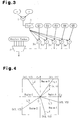
- Fig. 3 shows the operation of a determination device that performs the above determination.
- a divider 1 calculates y/x based on the coordinates x, y of the input point P and provides the coordinates x, y to a calculation section 2.
- the calculation section 2 computes tan -1 (y/x) to obtain the angle ⁇ P formed between the input point P and the lateral axis and provides the angle ⁇ P to comparators 3a to 3e.
- the comparators 3a to 3e compare the angle ⁇ P with the angles ⁇ 1 to ⁇ 5 and provides the comparison result to a determiner 4.
- Region codes corresponding to regions A to E are input to the determiner 4. Based on the comparison results of the comparators 3a to 3e, the determiner 4 outputs the region code corresponding to the region to which the input point P belongs. Then, based on the region code output from the determiner 4, a predetermined adjustment is performed on the color phase of the input point P.
- an outer product of the coordinates x, y of the input point P and vectors (x1, y1 to x5, y5) of each of the five boundary lines L1 to L5, which define regions A to E, is computed.
- the value of (x ⁇ y1)-(y ⁇ x1) is computed.
- the values of (x ⁇ y2)-(y ⁇ x2), (x ⁇ y3)-(y ⁇ x3), (x ⁇ y4)-(y ⁇ x4), and (x ⁇ y5)-(y ⁇ x5) are computed.
- An outer product having a negative value indicates that the input point P is located in a right semicircle of the corresponding one of the boundary lines L1 to L5.
- An outer product having a positive value indicates that the input point P is located in a left semicircle of the corresponding one of the boundary lines L1 to L5. The determination of the one of the regions to which the input point P belongs is determined in accordance with the values of the five outer products.
- Fig. 5 shows the operation of a determination device used in the second prior art example.
- Multipliers 5a to 5j perform the above multiplications.
- Subtracters 6a to 6e perform the above subtractions and provide the results to comparators 7a to 7e.
- the comparators 7a to 7e compare the computation results of the corresponding subtracters 6a to 6e and provide the comparison results to a determiner 8. Based on the comparison results of the comparators 7a to 7e, the determiner 8 outputs the region code corresponding to the region to which the input point P belongs. Then, based on the region code output from the determiner 8, a predetermined adjustment for the color phase of the input point P is performed.
- Japanese Laid-Open Patent Publication Nos. 10-257334 and 2001-285655 describe defining chrominance space regions with lines extending through the origin and determining the color phase based on the region.
- Japanese Laid-Open Patent Publication No. 9-247701 describes performing color correction for each region defined in the chrominance space.
- Japanese Laid-Open Patent Publication No. 11-341507 describes a color determination in the Cb-Cr space and a color signal correction process that is based on the determination result.
- the division of y/x based on the coordinates x, y of the input point P and the computation of tan -1 (y/x) are burdensome. Further, the divider 1 and the calculation section 2 have a large circuit scale, and a chip in which the divider 1 and the calculation section 2 are provided consumes much power.
- the outer products of the coordinates x, y of the input point P and the vectors (x1, y1 to x5, y5) of the five boundary lines L1 to L5 defining the regions A to E must be computed. Further, the multipliers 5a to 5k must perform multiplications for a number of times that is two times greater than the quantity of the boundary lines. As the number of regions increases, the multiplication processing amount drastically increases and enlarges the circuit scale of the multiplier. This increases the power consumption of the chip in which the multiplier is provided.
- a chrominance space region determination method for determining which one of regions in a chrominance space an input point belongs to.
- the chrominance space has an origin, a Cb axis, and a Cr axis, and the regions are defined by boundary lines.
- the method includes generating in the chrominance space a first line, extending through the input point and the origin, and a second line, connecting a point on the Cb axis and a point on the Cr axis.
- the method further includes comparing one or more coordinates of a first intersection point, at which the first line and the second line intersect, to coordinates of second intersection points, at which the second line and the boundary lines intersect, to determine the region to which the input point belongs.
- a chrominance space region determination apparatus for determining which one of regions in a chrominance space an input point belongs to.
- the chrominance space has an origin, a Cb axis, and a Cr axis, and the regions are defined by boundary lines.
- the apparatus includes a coordinate calculation unit for computing coordinates of a first intersection point in the chrominance space at which a first line, extending through the input point and the origin, intersects with a second line, connecting a point on the Cb axis and a point on the Cr axis.
- a determination device compares the coordinates of the first intersection point with coordinates of second intersection points, at which the second line and the boundary lines intersect, to determine the region to which the input point belongs.
- Cb coordinates X1 and X2 of intersection points P1 and P2 of the boundary lines L13 and L 14 and a line L12 are computed.
- the Cb coordinates X1 and X2 are boundary setting values.
- the coordinates X1 and X2, which are boundary setting values, and the coordinate Xp are compared to enable determination of which one of the regions to C the input point P (Pa in Fig. 9) belongs to.
- Fig. 6 shows a case in which the input point P is located in the first quadrant of the chrominance space. If the input point P is located in any one of the second to fourth quadrants, the quadrant is rotated about the origin O to overlap with the first quadrant, as shown in Fig. 8.
- the quadrant is rotated to the first quadrant and the coordinates become P(y, -x).
- the quadrant is rotated to the first quadrant and the coordinates become P(-x, -y).
- the quadrant is rotated to the first quadrant and the coordinates become P(-y, x).
- a Cb coordinate Xp of the intersection point of the line L12 and a line connecting each coordinate and the origin O is computed.
- the Cb coordinate of the line L12 and the boundary lines dividing the chrominance space is computed.
- the Cb coordinates are then compared with the Cb coordinate Xp.
- the region determination method will now be described with reference to Fig. 10.
- the quadrant to which input point P belongs to is determined.
- a quadrant conversion process is performed to rotate the quadrant to which the input point P belongs so that the quadrant overlaps with the first quadrant at steps S1 and S2.
- the determined quadrant Z is provided to the selector 11 at step S3, and the coordinates xa, ya of the input point Pa that has undergone the quadrant conversion process is computed at step S4. Then, the Cb coordinate Xp is calculated based on the coordinates xa, ya of the input point Pa at steps S5 and S6.
- the boundary setting values of the first to fourth quadrants are input to the selector 11.
- the boundary setting values of the second to fourth quadrants are converted beforehand to values corresponding to a state rotated to the first quadrant.
- the boundary setting value corresponding to the quadrant z input to the selector 11 is selected and output as the boundary setting value of the selected quadrant at step S7.
- region determination is performed based on the selected boundary setting value and the Cb coordinate Xp at step S8, and the determination result is output at step S9.
- Fig. 11 shows an example for performing the above region determination process.
- a comparator 12a compares coordinate x of the input point P with 0 and provides the comparison result to selectors 13a to 13c.
- a comparator 12b compares the coordinate y of the input point P with 0 and provides the comparison result to the selectors 13a to 13c.
- the selector 13a selects and outputs one of x, y, - x, and -y, which are obtained from the coordinates x, y of the input point P, as a coordinate xa subsequent to the quadrant rotation process.
- the selector 13b selects and outputs one of y, -x, -y, and x, which are obtained from the coordinates x, y of the input point P, as a coordinate ya subsequent to the quadrant rotation process.
- the comparators 12a and 12b and the selectors 13a and 13b perform the quadrant determination process and the quadrant conversion process.
- the comparators 12a and 12b function as a quadrant determiner.
- the selectors 13a and 13b function as a quadrant converter.
- a coordinate calculation unit includes a multiplier 14, a divider 15, an adder 16, the comparators 12a and 12b, and the selectors 13a and 13b.
- the coordinates xa output from the selector 13a is provided to the multiplier 14.
- a numerical value k is input to the multiplier 14 to set 2 k .
- the multiplier 14 performs the computation of 2 k ⁇ xa and provides the result to the divider 15.
- the coordinate xa output from the selector 13a and a coordinate ya output from the selector 13b are provided to the adder 16.
- the adder 16 performs the computation of xa+ya and provides the computation result to the divider 15.
- the divider 15 performs the division of 2 k ⁇ x/a(xa+ya) to compute coordinate Xp, which is provided to the comparators 17a to 17d.
- the boundary setting values of the first to fourth quadrants are input beforehand to the selector 13c as the values of the quadrants when rotated to the first quadrant.
- Fig. 11 shows a case in which each quadrant includes five regions defined by four boundary setting regions.
- the selector 13c selects the boundary setting values of the quadrant corresponding to the input point P and provides the selected boundary setting values to the comparators 17a to 17d.
- the comparators 17a to 17d compare the coordinate Xp to the boundary setting values of the selected quadrant and provide the comparison results to the determiner 18.
- the comparators 17a to 17d and the determiner 18 function as a determination device.
- Region codes corresponding to the five regions and the comparison results of the comparators 12a and 12b are input to the determiner 18. Based on the comparison results of the comparators 12a and 12b and the comparators 17a to 17d, the region code corresponding to the quadrant and the region to which the input point P belongs is output.
- the preferred embodiment has the advantages described below.
- the quadrant determination and quadrant conversion may be eliminated. This would further simplify the region determination process.
Landscapes
- Engineering & Computer Science (AREA)
- Multimedia (AREA)
- Signal Processing (AREA)
- Image Analysis (AREA)
- Facsimile Image Signal Circuits (AREA)
- Color Image Communication Systems (AREA)
- Image Processing (AREA)
- Spectrometry And Color Measurement (AREA)
Abstract
Description
- This application is based upon and claims the benefit of priority from prior
Japanese Patent Application No. 2005-366968, filed on December 20, 2005 - The present invention relates to a method and apparatus for determining the region of a chrominance space in which an input point (a point to be determined) included in an image signal is located.
- Various types of image capturing devices and image reproducing devices determine the region of a chrominance space in which an input point for an image signal is located. Based on the determination result, such devices perform image processing for adjusting or converting the color phase of the image signal. It is desirable that the efficiency for such determination be increased.
- The determination of the color phase for an image signal in a chrominance space (Cb-Cr space) will now be discussed with reference to Fig. 1. The region (one of A to E) in the Cb-Cr space to which an input point P of coordinates x, y belongs is determined for determining the color phase. Regions A to E are defined by five boundary lines L1 to L5, which extend through the origin O.
- Fig. 2 shows a first prior art example of a method for determining the region of the chrominance space to which the input point P belongs. First, an angle αP formed between a line segment, which connects the input point P with the origin O, and a lateral axis (Cb axis) of the Cb-Cr space is calculated. More specifically, from coordinates x, y, tan αP is obtained by y/x. Thus, αP is obtained from tan-1(y/x).
- The angle αP is then compared with angles α1 to α5, which are formed between the boundary lines L1 to L5 and the lateral axis. This leads to the determination of which one of regions A to E the input point P belongs to.
- Fig. 3 shows the operation of a determination device that performs the above determination. A
divider 1 calculates y/x based on the coordinates x, y of the input point P and provides the coordinates x, y to acalculation section 2. Thecalculation section 2 computes tan-1(y/x) to obtain the angle αP formed between the input point P and the lateral axis and provides the angle αP to comparators 3a to 3e. - The comparators 3a to 3e compare the angle αP with the angles α1 to α5 and provides the comparison result to a determiner 4.
- Region codes corresponding to regions A to E are input to the determiner 4. Based on the comparison results of the comparators 3a to 3e, the determiner 4 outputs the region code corresponding to the region to which the input point P belongs. Then, based on the region code output from the determiner 4, a predetermined adjustment is performed on the color phase of the input point P.
- A second prior art example of a method for determining the region in the chrominance space to which the input point P belongs will now be described with reference to Fig. 4.
- First, an outer product of the coordinates x, y of the input point P and vectors (x1, y1 to x5, y5) of each of the five boundary lines L1 to L5, which define regions A to E, is computed. For example, with regard to the vector x1, y1 of the boundary line L1 and the coordinates x, y of the input point P, the value of (x×y1)-(y×x1) is computed. In the same manner, with regard to the vectors L2 to L5, the values of (x×y2)-(y×x2), (x×y3)-(y×x3), (x×y4)-(y×x4), and (x×y5)-(y×x5) are computed.
- An outer product having a negative value indicates that the input point P is located in a right semicircle of the corresponding one of the boundary lines L1 to L5. An outer product having a positive value indicates that the input point P is located in a left semicircle of the corresponding one of the boundary lines L1 to L5. The determination of the one of the regions to which the input point P belongs is determined in accordance with the values of the five outer products.
- Fig. 5 shows the operation of a determination device used in the second prior art example.
Multipliers 5a to 5j perform the above multiplications. Subtracters 6a to 6e perform the above subtractions and provide the results tocomparators 7a to 7e. - The
comparators 7a to 7e compare the computation results of the corresponding subtracters 6a to 6e and provide the comparison results to adeterminer 8. Based on the comparison results of thecomparators 7a to 7e, thedeterminer 8 outputs the region code corresponding to the region to which the input point P belongs. Then, based on the region code output from thedeterminer 8, a predetermined adjustment for the color phase of the input point P is performed. -
Japanese Laid-Open Patent Publication Nos. 10-257334 2001-285655 Japanese Laid-Open Patent Publication No. 9-247701 Japanese Laid-Open Patent Publication No. 11-341507 - In the determination method shown in Fig. 2, the division of y/x based on the coordinates x, y of the input point P and the computation of tan-1(y/x) are burdensome. Further, the
divider 1 and thecalculation section 2 have a large circuit scale, and a chip in which thedivider 1 and thecalculation section 2 are provided consumes much power. - In the determination method of Fig. 4, the outer products of the coordinates x, y of the input point P and the vectors (x1, y1 to x5, y5) of the five boundary lines L1 to L5 defining the regions A to E must be computed. Further, the
multipliers 5a to 5k must perform multiplications for a number of times that is two times greater than the quantity of the boundary lines. As the number of regions increases, the multiplication processing amount drastically increases and enlarges the circuit scale of the multiplier. This increases the power consumption of the chip in which the multiplier is provided. - Accordingly, it is a consideration of the present invention to provide a method and device for determining a region in a chrominance space with few computations.
- According to a first aspect of the present invention, there is provided a chrominance space region determination method for determining which one of regions in a chrominance space an input point belongs to. The chrominance space has an origin, a Cb axis, and a Cr axis, and the regions are defined by boundary lines. The method includes generating in the chrominance space a first line, extending through the input point and the origin, and a second line, connecting a point on the Cb axis and a point on the Cr axis. The method further includes comparing one or more coordinates of a first intersection point, at which the first line and the second line intersect, to coordinates of second intersection points, at which the second line and the boundary lines intersect, to determine the region to which the input point belongs.
- In an embodiment of the present invention, there is provided a chrominance space region determination apparatus for determining which one of regions in a chrominance space an input point belongs to. The chrominance space has an origin, a Cb axis, and a Cr axis, and the regions are defined by boundary lines. The apparatus includes a coordinate calculation unit for computing coordinates of a first intersection point in the chrominance space at which a first line, extending through the input point and the origin, intersects with a second line, connecting a point on the Cb axis and a point on the Cr axis. A determination device compares the coordinates of the first intersection point with coordinates of second intersection points, at which the second line and the boundary lines intersect, to determine the region to which the input point belongs.
- Other aspects and advantages of the present invention will become apparent from the following description, taken in conjunction with the accompanying drawings, illustrating by way of example the principles of the invention.
- The invention, together with advantages thereof, may best be understood by reference to the following description of the presently preferred embodiments together with the accompanying drawings in which:
- Figs. 1 and 2 are explanatory diagrams showing a region determination process in a first prior art example;
- Fig. 3 is a block diagram of a region determination region in the first prior art example;
- Fig. 4 is an explanatory diagram showing a region determination process in a second prior art example;
- Fig. 5 is a block diagram of a region determination region in the second prior art example;
- Figs. 6 to 9 are explanatory diagrams showing a region determination process according to a preferred embodiment of the present invention;
- Fig. 10 is a flowchart showing a region determination process of the preferred embodiment; and
- Fig. 11 is a block diagram showing a region determination device of the preferred embodiment.
- A chrominance space region determination method according to a preferred embodiment of the present invention will now be discussed.
- In Fig. 6, a line L11 (first line) connecting an input point P at coordinates x, y with origin O is represented by x·Cr=y·Cb. First, a Cb coordinate Xp of an intersection point Pp of the line L11 and a line L12 (second line) represented by Cb+Cr=2k (k=1, 2, 3, ...) is computed. The Cb coordinate Xp satisfies Xp=2k×x/(x+y).
- Then, referring to Fig. 7, with regard to boundary lines L13 and L14 defining regions A to C in the chrominance region, Cb coordinates X1 and X2 of intersection points P1 and P2 of the boundary lines L13 and
L 14 and a line L12 are computed. The Cb coordinates X1 and X2 are boundary setting values. - Referring to Fig. 9, the coordinates X1 and X2, which are boundary setting values, and the coordinate Xp are compared to enable determination of which one of the regions to C the input point P (Pa in Fig. 9) belongs to.
- Fig. 6 shows a case in which the input point P is located in the first quadrant of the chrominance space. If the input point P is located in any one of the second to fourth quadrants, the quadrant is rotated about the origin O to overlap with the first quadrant, as shown in Fig. 8.
- More specifically, when the input point P at coordinates x, y is located in the second quadrant, the quadrant is rotated to the first quadrant and the coordinates become P(y, -x). When the input point P at coordinates x, y is located in the third quadrant, the quadrant is rotated to the first quadrant and the coordinates become P(-x, -y). When the input point P at coordinates x, y is located in the third quadrant, the quadrant is rotated to the first quadrant and the coordinates become P(-y, x).
- Then, a Cb coordinate Xp of the intersection point of the line L12 and a line connecting each coordinate and the origin O is computed. With regard to the second to fourth quadrants, the Cb coordinate of the line L12 and the boundary lines dividing the chrominance space is computed. The Cb coordinates are then compared with the Cb coordinate Xp.
- The region determination method will now be described with reference to Fig. 10. The quadrant to which input point P belongs to is determined. When the input point P belongs to any one of the second to fourth quadrants, a quadrant conversion process is performed to rotate the quadrant to which the input point P belongs so that the quadrant overlaps with the first quadrant at steps S1 and S2.
- The determined quadrant Z is provided to the selector 11 at step S3, and the coordinates xa, ya of the input point Pa that has undergone the quadrant conversion process is computed at step S4. Then, the Cb coordinate Xp is calculated based on the coordinates xa, ya of the input point Pa at steps S5 and S6.
- The boundary setting values of the first to fourth quadrants are input to the selector 11. The boundary setting values of the second to fourth quadrants are converted beforehand to values corresponding to a state rotated to the first quadrant. The boundary setting value corresponding to the quadrant z input to the selector 11 is selected and output as the boundary setting value of the selected quadrant at step S7.
- Then, region determination is performed based on the selected boundary setting value and the Cb coordinate Xp at step S8, and the determination result is output at step S9.
- Fig. 11 shows an example for performing the above region determination process. A
comparator 12a compares coordinate x of the input point P with 0 and provides the comparison result toselectors 13a to 13c. Acomparator 12b compares the coordinate y of the input point P with 0 and provides the comparison result to theselectors 13a to 13c. - Based on the comparison results of the
comparators selector 13a selects and outputs one of x, y, - x, and -y, which are obtained from the coordinates x, y of the input point P, as a coordinate xa subsequent to the quadrant rotation process. - Based on the comparison results of the
comparators selector 13b selects and outputs one of y, -x, -y, and x, which are obtained from the coordinates x, y of the input point P, as a coordinate ya subsequent to the quadrant rotation process. - The
comparators selectors comparators selectors multiplier 14, adivider 15, anadder 16, thecomparators selectors - The coordinates xa output from the
selector 13a is provided to themultiplier 14. A numerical value k is input to themultiplier 14 to set 2k. Themultiplier 14 performs the computation of 2k×xa and provides the result to thedivider 15. - The coordinate xa output from the
selector 13a and a coordinate ya output from theselector 13b are provided to theadder 16. Theadder 16 performs the computation of xa+ya and provides the computation result to thedivider 15. Thedivider 15 performs the division of 2k×x/a(xa+ya) to compute coordinate Xp, which is provided to the comparators 17a to 17d. - The boundary setting values of the first to fourth quadrants are input beforehand to the
selector 13c as the values of the quadrants when rotated to the first quadrant. Fig. 11 shows a case in which each quadrant includes five regions defined by four boundary setting regions. Based on the comparison results of thecomparators selector 13c selects the boundary setting values of the quadrant corresponding to the input point P and provides the selected boundary setting values to the comparators 17a to 17d. - The comparators 17a to 17d compare the coordinate Xp to the boundary setting values of the selected quadrant and provide the comparison results to the
determiner 18. The comparators 17a to 17d and thedeterminer 18 function as a determination device. - Region codes corresponding to the five regions and the comparison results of the
comparators determiner 18. Based on the comparison results of thecomparators - The preferred embodiment has the advantages described below.
- (1) The region in the chrominance space to which the input point P belongs is determined based on the coordinates x, y of the input point P.
- (2) In the region determination process, multiplication, addition, division, comparison of the coordinate Xp and the boundary setting values of the coordinate Xp are performed only once. Thus, there is no need to perform a non-linear computation such a tan-1. Accordingly, the circuit scale of the coordinate calculation unit, which includes the
multiplier 14, thedivider 15, and theadder 16, is not enlarged. This prevents the circuit area and power consumption of the coordinate calculation unit from increasing. - (3) Even if the number of regions increases, this may be coped by simply increasing the number of comparators for comparing the coordinate Xp to the boundary setting values of the selected quadrant. Accordingly, the amount of computations and the circuit scale are prevented from being increased.
- (4) Even if the input point P is located in any one of the first to fourth quadrants of the chrominance space, the region to which the input point P belongs to in the quadrant can be determined.
- It should be apparent to those skilled in the art that the present invention may be embodied in many other specific forms without departing from the scope of the invention. Particularly, it should be understood that the present invention may be embodied in the following forms.
- In the preferred embodiment, if the chrominance space has only the first quadrant, the quadrant determination and quadrant conversion may be eliminated. This would further simplify the region determination process.
- The present examples and embodiments are to be considered as illustrative and not restrictive, and the invention is not to be limited to the details given herein, but may be modified within the scope of the appended claims.
Claims (7)
- A chrominance space region determination method for determining which one of regions in a chrominance space an input point belongs to, the chrominance space having an origin, a Cb axis, and a Cr axis, and the regions being defined by boundary lines, the method being characterized by:generating in the chrominance space a first line, extending through the input point and the origin, and a second line, connecting a point on the Cb axis and a point on the Cr axis; andcomparing coordinates of a first intersection point, at which the first line and the second line intersect, and coordinates of second intersection points, at which the second line and the boundary lines intersect, to determine the region to which the input point belongs.
- The chrominance space region determination method according to claim 1, wherein the chrominance space is a Cb-Cr space, and the second line is represented by the expression of Cb+Cr=2k (k=1, 2, 3, ...).
- The chrominance space region determination method according to claim 1, wherein the chrominance space includes a first quadrant, a second quadrant, a third quadrant, and a fourth quadrant, and said comparing includes converting the coordinates of the first intersection point and the coordinates of the second intersection points to coordinates in the first quadrant when the input point is located in one of the second to fourth quadrants and comparing the converted coordinates of the first intersection point with the converted coordinates of the second intersection points.
- The chrominance space region determination method according to claim 3, wherein said comparing includes:determining which one of the first to fourth quadrants the input point is located in based on coordinates of the input point;when the input point is located in a quadrant other than the first quadrant, converting the coordinates of the input point based on the determination result to coordinates corresponding to the first quadrant;selecting the coordinates of the second intersection point corresponding to the quadrant the input point is located in based on the determination result; andcomparing the selected coordinates with the coordinates of the input point.
- The chrominance space region determination method according to any one of claims 1 to 4, wherein said comparing includes comparing a Cb coordinates of the first intersection point and a Cb coordinates of the first intersection point without comparing a Cr coordinates of the first intersection point and a Cr coordinates of the first intersection point.
- A chrominance space region determination apparatus for determining which one of regions in a chrominance space an input point belongs to, the chrominance space having an origin, a Cb axis, and a Cr axis, and the regions being defined by boundary lines, the apparatus being characterized by:a coordinate calculation unit for computing coordinates of a first intersection point in the chrominance space at which a first line, extending through the input point and the origin, intersects with a second line, connecting a point on the Cb axis and a point on the Cr axis; anda determination device for comparing the coordinates of the first intersection point with coordinates of second intersection points, at which the second line and the boundary lines intersect, to determine the region to which the input point belongs.
- The chrominance space region determination apparatus according to claim 6, wherein the coordinate calculation unit includes:a quadrant determiner for determining the quadrant to which the input point belongs to based on coordinates of the input point; anda quadrant converter for converting, when the input point is located in a quadrant other than a first quadrant, the coordinates of the first intersection point and the coordinates of the second intersection points to coordinates in the first quadrant.
Applications Claiming Priority (1)
| Application Number | Priority Date | Filing Date | Title |
|---|---|---|---|
| JP2005366968A JP4676872B2 (en) | 2005-12-20 | 2005-12-20 | Color difference space region determination method and determination apparatus |
Publications (2)
| Publication Number | Publication Date |
|---|---|
| EP1802098A1 true EP1802098A1 (en) | 2007-06-27 |
| EP1802098B1 EP1802098B1 (en) | 2008-06-25 |
Family
ID=36794930
Family Applications (1)
| Application Number | Title | Priority Date | Filing Date |
|---|---|---|---|
| EP06251654A Expired - Lifetime EP1802098B1 (en) | 2005-12-20 | 2006-03-28 | Method and apparatus for determining chrominance space |
Country Status (7)
| Country | Link |
|---|---|
| US (1) | US7671872B2 (en) |
| EP (1) | EP1802098B1 (en) |
| JP (1) | JP4676872B2 (en) |
| KR (1) | KR100765227B1 (en) |
| CN (1) | CN1988593B (en) |
| DE (1) | DE602006001569D1 (en) |
| TW (1) | TWI311023B (en) |
Citations (6)
| Publication number | Priority date | Publication date | Assignee | Title |
|---|---|---|---|---|
| US4244653A (en) * | 1977-05-25 | 1981-01-13 | Fuji Photo Film Co., Ltd. | Color detecting device for color printer |
| GB2208460A (en) * | 1987-07-24 | 1989-03-30 | Nippon Denki Home Electronics | Color signal compensating system |
| US4989080A (en) * | 1988-03-08 | 1991-01-29 | Ricoh Company, Ltd. | Color correction device with a hue area judgment unit to determine correction parameters |
| JP2000354252A (en) * | 1999-06-11 | 2000-12-19 | Sony Corp | Hue discrimination circuit |
| JP2002330299A (en) * | 2001-05-01 | 2002-11-15 | Seiko Epson Corp | Image processing apparatus, image processing method, program, and recording medium |
| US20040119721A1 (en) * | 2002-12-20 | 2004-06-24 | Samsung Electronics Co., Ltd. | Color signal processing device and method |
Family Cites Families (10)
| Publication number | Priority date | Publication date | Assignee | Title |
|---|---|---|---|---|
| JP3456818B2 (en) | 1996-03-04 | 2003-10-14 | 株式会社日立国際電気 | Color correction device |
| JPH10178557A (en) * | 1996-10-14 | 1998-06-30 | Oki Data:Kk | Color image processing method |
| JP3713352B2 (en) * | 1996-11-22 | 2005-11-09 | 株式会社リコー | Color correction processing device |
| JPH10257333A (en) * | 1997-01-07 | 1998-09-25 | Ricoh Co Ltd | Image processing device |
| JPH11341507A (en) | 1998-05-26 | 1999-12-10 | Mitsubishi Electric Corp | Color signal correction device |
| US6788441B1 (en) * | 1999-01-28 | 2004-09-07 | Ricoh Company, Ltd. | Color image processing apparatus, image processing apparatus, color image processing method, image processing method, and a computer-readable recording medium for making a computer execute the methods |
| JP2001285655A (en) | 1999-05-31 | 2001-10-12 | Ricoh Co Ltd | Color image processing apparatus, image processing apparatus, color signal processing apparatus, color image processing method, image processing method, color signal processing method, and computer-readable recording medium storing a program for causing a computer to execute the methods |
| US6798449B2 (en) * | 2001-01-18 | 2004-09-28 | Kinpo Electronics, Inc. | Automatic white-balance correction for digital camera |
| FI113930B (en) * | 2002-05-31 | 2004-06-30 | Oplayo Oy | Procedure and arrangement for compression of digital images |
| JP4031299B2 (en) * | 2002-06-21 | 2008-01-09 | 富士フイルム株式会社 | Color image signal processing method, color image output apparatus, and photographing apparatus |
-
2005
- 2005-12-20 JP JP2005366968A patent/JP4676872B2/en not_active Expired - Fee Related
-
2006
- 2006-03-28 EP EP06251654A patent/EP1802098B1/en not_active Expired - Lifetime
- 2006-03-28 DE DE602006001569T patent/DE602006001569D1/en not_active Expired - Lifetime
- 2006-04-07 TW TW095112436A patent/TWI311023B/en not_active IP Right Cessation
- 2006-04-11 US US11/401,309 patent/US7671872B2/en not_active Expired - Fee Related
- 2006-04-14 KR KR1020060033894A patent/KR100765227B1/en not_active Expired - Fee Related
- 2006-04-17 CN CN2006100724672A patent/CN1988593B/en not_active Expired - Fee Related
Patent Citations (6)
| Publication number | Priority date | Publication date | Assignee | Title |
|---|---|---|---|---|
| US4244653A (en) * | 1977-05-25 | 1981-01-13 | Fuji Photo Film Co., Ltd. | Color detecting device for color printer |
| GB2208460A (en) * | 1987-07-24 | 1989-03-30 | Nippon Denki Home Electronics | Color signal compensating system |
| US4989080A (en) * | 1988-03-08 | 1991-01-29 | Ricoh Company, Ltd. | Color correction device with a hue area judgment unit to determine correction parameters |
| JP2000354252A (en) * | 1999-06-11 | 2000-12-19 | Sony Corp | Hue discrimination circuit |
| JP2002330299A (en) * | 2001-05-01 | 2002-11-15 | Seiko Epson Corp | Image processing apparatus, image processing method, program, and recording medium |
| US20040119721A1 (en) * | 2002-12-20 | 2004-06-24 | Samsung Electronics Co., Ltd. | Color signal processing device and method |
Non-Patent Citations (2)
| Title |
|---|
| PATENT ABSTRACTS OF JAPAN vol. 2000, no. 15 6 April 2001 (2001-04-06) * |
| PATENT ABSTRACTS OF JAPAN vol. 2003, no. 03 5 May 2003 (2003-05-05) * |
Also Published As
| Publication number | Publication date |
|---|---|
| CN1988593B (en) | 2010-12-29 |
| US7671872B2 (en) | 2010-03-02 |
| JP2007174103A (en) | 2007-07-05 |
| EP1802098B1 (en) | 2008-06-25 |
| TWI311023B (en) | 2009-06-11 |
| JP4676872B2 (en) | 2011-04-27 |
| TW200726207A (en) | 2007-07-01 |
| CN1988593A (en) | 2007-06-27 |
| DE602006001569D1 (en) | 2008-08-07 |
| KR100765227B1 (en) | 2007-10-10 |
| US20070139738A1 (en) | 2007-06-21 |
| KR20070065767A (en) | 2007-06-25 |
Similar Documents
| Publication | Publication Date | Title |
|---|---|---|
| CN101151907B (en) | Method and device for adaptive color interpolation | |
| JP2009093662A (en) | Data processing apparatus and method for converting number between fixed-point and floating-point representations | |
| TW201030607A (en) | Instruction and logic for performing range detection | |
| JPH05241794A (en) | Device for approximating transcendental function and its method | |
| CN111953953A (en) | Method and device for adjusting pixel brightness and electronic equipment | |
| KR101114785B1 (en) | Apparatus and computer readable recording medium for arctangent calculation | |
| EP1802098B1 (en) | Method and apparatus for determining chrominance space | |
| US20190213477A1 (en) | Micro-processor circuit and method of performing neural network operation | |
| CN108595148B (en) | A division function implementation method, circuit, chip and system | |
| US7941473B2 (en) | Calculation apparatus and storage medium in which calculation program is stored | |
| CN113867799B (en) | Computing device, integrated circuit chip, board, electronic device and computing method | |
| CN112422976B (en) | A luminance component motion compensation method in a video coding standard and a video coding method | |
| US20220188673A1 (en) | Mixed-precision ai processor and operating method thereof | |
| CN109783055B (en) | Floating-point number arithmetic circuit and method | |
| JP5997480B2 (en) | Image processing apparatus, image processing method, and program | |
| JP5939893B2 (en) | Image processing apparatus and image processing method | |
| JPS63155273A (en) | Image processor | |
| JP2002318792A (en) | Data operation processing device and data operation processing program | |
| CN110659650A (en) | Gradient direction calculating device | |
| JP3659408B2 (en) | Data arithmetic processing apparatus and data arithmetic processing program | |
| JP3645830B2 (en) | Divider failure detection circuit and divider failure detection method used therefor | |
| JP2512801B2 (en) | Multiplier | |
| JP3773033B2 (en) | Data arithmetic processing apparatus and data arithmetic processing program | |
| JPH0414173A (en) | Fixed point product sum computing element | |
| JP2010092412A (en) | Comparison method and comparator |
Legal Events
| Date | Code | Title | Description |
|---|---|---|---|
| PUAI | Public reference made under article 153(3) epc to a published international application that has entered the european phase |
Free format text: ORIGINAL CODE: 0009012 |
|
| 17P | Request for examination filed |
Effective date: 20061206 |
|
| AK | Designated contracting states |
Kind code of ref document: A1 Designated state(s): AT BE BG CH CY CZ DE DK EE ES FI FR GB GR HU IE IS IT LI LT LU LV MC NL PL PT RO SE SI SK TR |
|
| AX | Request for extension of the european patent |
Extension state: AL BA HR MK YU |
|
| GRAP | Despatch of communication of intention to grant a patent |
Free format text: ORIGINAL CODE: EPIDOSNIGR1 |
|
| AKX | Designation fees paid |
Designated state(s): DE FR GB |
|
| GRAS | Grant fee paid |
Free format text: ORIGINAL CODE: EPIDOSNIGR3 |
|
| GRAA | (expected) grant |
Free format text: ORIGINAL CODE: 0009210 |
|
| AK | Designated contracting states |
Kind code of ref document: B1 Designated state(s): DE FR GB |
|
| REG | Reference to a national code |
Ref country code: GB Ref legal event code: FG4D |
|
| RIN1 | Information on inventor provided before grant (corrected) |
Inventor name: WATARAI, YUJI,FUJITSU VLSI LIMITED |
|
| REF | Corresponds to: |
Ref document number: 602006001569 Country of ref document: DE Date of ref document: 20080807 Kind code of ref document: P |
|
| REG | Reference to a national code |
Ref country code: GB Ref legal event code: 732E |
|
| PLBE | No opposition filed within time limit |
Free format text: ORIGINAL CODE: 0009261 |
|
| STAA | Information on the status of an ep patent application or granted ep patent |
Free format text: STATUS: NO OPPOSITION FILED WITHIN TIME LIMIT |
|
| REG | Reference to a national code |
Ref country code: FR Ref legal event code: TP |
|
| 26N | No opposition filed |
Effective date: 20090326 |
|
| PGFP | Annual fee paid to national office [announced via postgrant information from national office to epo] |
Ref country code: FR Payment date: 20090206 Year of fee payment: 4 |
|
| GBPC | Gb: european patent ceased through non-payment of renewal fee |
Effective date: 20100328 |
|
| REG | Reference to a national code |
Ref country code: FR Ref legal event code: ST Effective date: 20101130 |
|
| PG25 | Lapsed in a contracting state [announced via postgrant information from national office to epo] |
Ref country code: FR Free format text: LAPSE BECAUSE OF NON-PAYMENT OF DUE FEES Effective date: 20100331 |
|
| PG25 | Lapsed in a contracting state [announced via postgrant information from national office to epo] |
Ref country code: GB Free format text: LAPSE BECAUSE OF NON-PAYMENT OF DUE FEES Effective date: 20100328 |
|
| REG | Reference to a national code |
Ref country code: DE Ref legal event code: R082 Ref document number: 602006001569 Country of ref document: DE Representative=s name: REICHERT & LINDNER PARTNERSCHAFT PATENTANWAELT, DE |
|
| REG | Reference to a national code |
Ref country code: DE Ref legal event code: R082 Ref document number: 602006001569 Country of ref document: DE Representative=s name: REICHERT & LINDNER PARTNERSCHAFT PATENTANWAELT, DE Effective date: 20150512 Ref country code: DE Ref legal event code: R081 Ref document number: 602006001569 Country of ref document: DE Owner name: SOCIONEXT INC., YOKOHAMA-SHI, JP Free format text: FORMER OWNER: FUJITSU SEMICONDUCTOR LTD., YOKOHAMA, KANAGAWA, JP Effective date: 20150512 |
|
| PGFP | Annual fee paid to national office [announced via postgrant information from national office to epo] |
Ref country code: DE Payment date: 20200320 Year of fee payment: 15 |
|
| REG | Reference to a national code |
Ref country code: DE Ref legal event code: R119 Ref document number: 602006001569 Country of ref document: DE |
|
| PG25 | Lapsed in a contracting state [announced via postgrant information from national office to epo] |
Ref country code: DE Free format text: LAPSE BECAUSE OF NON-PAYMENT OF DUE FEES Effective date: 20211001 |