EP1801931A1 - A connector and a method for controlling the assembly thereof - Google Patents
A connector and a method for controlling the assembly thereof Download PDFInfo
- Publication number
- EP1801931A1 EP1801931A1 EP06026216A EP06026216A EP1801931A1 EP 1801931 A1 EP1801931 A1 EP 1801931A1 EP 06026216 A EP06026216 A EP 06026216A EP 06026216 A EP06026216 A EP 06026216A EP 1801931 A1 EP1801931 A1 EP 1801931A1
- Authority
- EP
- European Patent Office
- Prior art keywords
- terminal
- resilient arm
- detecting
- housings
- shorting
- Prior art date
- Legal status (The legal status is an assumption and is not a legal conclusion. Google has not performed a legal analysis and makes no representation as to the accuracy of the status listed.)
- Granted
Links
- 238000000034 method Methods 0.000 title claims description 20
- 230000013011 mating Effects 0.000 claims description 7
- 230000009471 action Effects 0.000 claims description 6
- 238000000926 separation method Methods 0.000 claims description 3
- 238000004891 communication Methods 0.000 description 6
- 238000003780 insertion Methods 0.000 description 5
- 230000037431 insertion Effects 0.000 description 5
- 238000005192 partition Methods 0.000 description 5
- 238000010276 construction Methods 0.000 description 4
- 230000008569 process Effects 0.000 description 4
- 230000002159 abnormal effect Effects 0.000 description 3
- 239000000203 mixture Substances 0.000 description 3
- 229920003002 synthetic resin Polymers 0.000 description 3
- 239000000057 synthetic resin Substances 0.000 description 3
- 230000002093 peripheral effect Effects 0.000 description 2
- 238000005452 bending Methods 0.000 description 1
- 239000004020 conductor Substances 0.000 description 1
- 230000008878 coupling Effects 0.000 description 1
- 238000010168 coupling process Methods 0.000 description 1
- 238000005859 coupling reaction Methods 0.000 description 1
- 230000001419 dependent effect Effects 0.000 description 1
- 238000001514 detection method Methods 0.000 description 1
- 238000006073 displacement reaction Methods 0.000 description 1
- 239000002184 metal Substances 0.000 description 1
- 230000000717 retained effect Effects 0.000 description 1
Images


Classifications
-
- H—ELECTRICITY
- H01—ELECTRIC ELEMENTS
- H01R—ELECTRICALLY-CONDUCTIVE CONNECTIONS; STRUCTURAL ASSOCIATIONS OF A PLURALITY OF MUTUALLY-INSULATED ELECTRICAL CONNECTING ELEMENTS; COUPLING DEVICES; CURRENT COLLECTORS
- H01R13/00—Details of coupling devices of the kinds covered by groups H01R12/70 or H01R24/00 - H01R33/00
- H01R13/64—Means for preventing incorrect coupling
- H01R13/641—Means for preventing incorrect coupling by indicating incorrect coupling; by indicating correct or full engagement
-
- H—ELECTRICITY
- H01—ELECTRIC ELEMENTS
- H01R—ELECTRICALLY-CONDUCTIVE CONNECTIONS; STRUCTURAL ASSOCIATIONS OF A PLURALITY OF MUTUALLY-INSULATED ELECTRICAL CONNECTING ELEMENTS; COUPLING DEVICES; CURRENT COLLECTORS
- H01R13/00—Details of coupling devices of the kinds covered by groups H01R12/70 or H01R24/00 - H01R33/00
- H01R13/62—Means for facilitating engagement or disengagement of coupling parts or for holding them in engagement
- H01R13/629—Additional means for facilitating engagement or disengagement of coupling parts, e.g. aligning or guiding means, levers, gas pressure electrical locking indicators, manufacturing tolerances
- H01R13/62933—Comprising exclusively pivoting lever
- H01R13/62938—Pivoting lever comprising own camming means
-
- H—ELECTRICITY
- H01—ELECTRIC ELEMENTS
- H01R—ELECTRICALLY-CONDUCTIVE CONNECTIONS; STRUCTURAL ASSOCIATIONS OF A PLURALITY OF MUTUALLY-INSULATED ELECTRICAL CONNECTING ELEMENTS; COUPLING DEVICES; CURRENT COLLECTORS
- H01R13/00—Details of coupling devices of the kinds covered by groups H01R12/70 or H01R24/00 - H01R33/00
- H01R13/62—Means for facilitating engagement or disengagement of coupling parts or for holding them in engagement
- H01R13/629—Additional means for facilitating engagement or disengagement of coupling parts, e.g. aligning or guiding means, levers, gas pressure electrical locking indicators, manufacturing tolerances
- H01R13/62933—Comprising exclusively pivoting lever
- H01R13/62955—Pivoting lever comprising supplementary/additional locking means
Definitions
- the present invention relates to a connector and to a method of controlling the assembly thereof.
- a general construction of a connector provided with a lever is known from Japanese Unexamined Patent Publication No. 2003-86301 .
- This connector is constructed such that a lever formed with a cam groove is rotatably supported in one housing, and a cam pin engageable with the cam groove is provided in the other housing.
- the cam pin is engaged with the cam groove by lightly fitting the two housings when the lever is at an initial position, and the lever is rotated to a connection position to pull the two housings toward each other by the cam action resulting from the engagement of the cam groove and the cam pin, whereby the two housings reach a completely connected state.
- the lever includes a detecting member displaceable from a standby position to a detecting position. A displacement of the detecting member from the standby position to the detecting position is permitted with the lever located at the proper connection position while being prevented with the lever left at a partial connection position immediately before arriving the proper connection position.
- the connected state of the two housings is mechanically detected based on the rotational position of the lever.
- there has also been a demand for electrically detecting the connected state of the two housings and such a demand has needed to be met.
- the present invention was developed in view of the above situation and an object thereof is to reliably electrically detect the connected state of two housings.
- a connector comprising a first and a second housings connectable with each other, wherein:
- the first detecting terminal of the first housing is held in contact with the second detecting terminal of the second housing until the connecting operation is substantially completed, and the first detecting terminal is separated from the second detecting terminal when the connecting operation is completed.
- the connected state of the two housings can be electrically detected.
- the shorting terminal is to be held separated from the first terminal fitting after the short canceling member thrusts itself at least partly between the shorting terminal and the first terminal fittings as the connecting operation progresses.
- a connector comprising a first and a second housings connectable with each other, wherein:
- the shorting terminal is separated from the first terminal fittings after the first and second terminal fittings touch or contact each other.
- the shorting terminal is separated from the first terminal fittings after the first and second terminal fittings touch or contact each other, the first terminal fittings are electrically connected with the second terminal fittings when being freed from the shorted state thereof.
- the safety of the operation can be assured.
- a movable member operable to connect and separate the connector housings or to assist the connection and separation thereof by means of a cam action is provided on one of the connector housings.
- the operable member formed with at least one cam means is movably assembled into the first housing at a side of the resilient arm substantially opposite to the first detecting terminal, a mating cam means which can cooperate with the cam means is formed in the second housing.
- At least one pressing portion capable of pressing the resilient arm is formed at a portion of the movable member substantially facing the resilient arm, and wherein the pressing portion presses the resilient arm to hold the resilient arm resiliently deformed during the operation of the movable member while stopping pressing the resilient arm to resiliently at least partly restore the resilient arm when the connecting operation is substantially completed.
- a lever formed with a cam groove is rotatably assembled into the first housing at a side of the resilient arm opposite to the first detecting terminal, a cam pin movable along the cam groove is formed in the second housing, a pressing portion capable of pressing the resilient arm is formed at a portion of the lever facing the resilient arm, and the pressing portion presses the resilient arm to hold the resilient arm resiliently deformed during the rotation of the lever while stopping pressing the resilient arm to resiliently restore the resilient arm when the connecting operation is completed.
- the cam pin is introduced into the cam groove by lightly fitting the two housings to each other.
- the cam pin moves along the cam groove to progress the connecting operation of the two housings. Since the pressing portion provided on the lever presses the resilient arm to resiliently deform the resilient arm during this time, the first detecting terminal is held in contact with the second detecting terminal.
- the connecting operation of the two housings is completed as the lever is rotated, the resilient arm is freed from the pressed state, wherefore the resilient arm is resiliently restored to separate the first detecting terminal from the second detecting terminal.
- the resilient arm is formed into a cantilever resiliently deformable with a side thereof toward a connecting surface as a base end by cutting part of an inner wall of the detecting terminal accommodating portion for at least partly accommodating the first detecting terminal along a connecting direction of the first and second housings, and/or a pressable portion to be touched by the pressing portion is formed at or near a free end of the resilient arm, and a contact projection that (directly or indirectly) comes into contact with the first detecting terminal is formed at an intermediate position, preferably substantially at a longitudinal middle position, of the resilient arm.
- the first detecting terminal is at least partly accommodated in the detecting terminal accommodating portion and the resilient arm is formed by cutting part of the inner wall of the detecting terminal accommodating portion, wherefore the first detecting terminal can be protected without being exposed to the outside. Since the first detecting terminal is resiliently deformed utilizing the lever principle by providing the pressable portion at or near the free end of the resilient arm and providing the contact projection in an intermediate position, preferably substantially in the longitudinal center, of the resilient arm, an operation force exerted upon pressing the pressable portion can be reduced.
- a method of controlling or performing the assembly of a connector comprising a first and a second housings connectable with each other, comprising the following steps:
- the first detecting terminal of the first housing is held in contact with the second detecting terminal of the second housing until the connecting operation is substantially completed, and the first detecting terminal is separated from the second detecting terminal when the connecting operation is completed.
- the connected state of the two housings can be electrically detected.
- the shorting terminal for shorting the adjacent first terminal fittings before the connecting operation of the two housings up to a specified (predetermined or predeterminable) timing during the connecting operation is arranged in the first housing, such a controlling method is adopted according to which at least either one of the first detecting terminal and the shorting terminal is in contact with the mating partner (electrically connected state) in the entire connected state except the completely connected state of the two housings, and both the first detecting terminal and the shorting terminal are to be separated from the mating partners (electrically unconnected state) in the substantially completely connected state of the two housings.
- such a controlling method is adopted according to which "circuits are opened" as the connecting operation is completed.
- the shorting terminal is held separated from the first terminal fitting after the short canceling member thrusts itself at least partly between the shorting terminal and the first terminal fittings as the connecting operation progresses.
- a connector of this embodiment particularly is a connector for an airbag and is provided with one or more first housings 10 and a second housing 30 connectable with each other.
- the two housings 10, 30 can be connected by operating an operable member, preferably by rotating or pivoting a lever 40 rotatably or pivotably assembled at least partly into or onto the first housing 10.
- sides of the first and second housings 10, 30 to be connected are referred to as front sides concerning forward and backward directions FBD.
- the second housing 30 is made e.g. of a synthetic resin and has a receptacle 31 having an open front surface as shown in FIG. 7.
- the receptacle 31 preferably substantially has the shape of a transversely long rectangle when viewed from front, and at least one partition wall 31A substantially vertically extends in an intermediate position (preferably substantially in the transverse center) of the receptacle 31.
- the interior of the receptacle 31 is divided by the partition wall(s) 31A into a plurality (preferably a pair) of lateral (left and right) fitting recesses 31B into which the first housings 10 can be individually at least partly accommodated.
- FIGS. 7 to 12 only the right fitting recess 31B when viewed from front is shown in FIGS. 7 to 12 and the construction of only the fitting recess 31B at the shown side is described below, however all the fitting recesses preferably have a similar or substantially same configuration.
- each fitting recess 31B one or more, preferably a plurality of second terminal fittings 32 preferably in the form of tabs are transversely arranged substantially side by side at one or more stages, preferably at each of three (upper, middle or intermediate and lower) stages.
- One or more, preferably two second detecting terminals 39 are preferably transversely arranged substantially side by side at a side of the second terminal fittings 32 at the upper stage near the partition wall 31A.
- the second detecting terminals 39 preferably have the substantially same shape and/or substantially same projecting height as the second terminal fittings 32.
- the second detecting terminals 39 are to be electrically connected with first detecting terminals 11 of the first housing 10 to close a connection detecting circuit for detecting or checking the connected state of the two housings 10, 30 as the two housings 10, 30 are connected.
- each of the second terminal fittings 32 and the second detecting terminals 39 projects backward through a back wall 33 of the fitting recess 31B, is bent at an angle different from 0° or 180°, preferably substantially down substantially at right angle at an intermediate position, and has the bottom end thereof electrically is to be connected with a detecting device (such as a conductor path of an unillustrated printed circuit board thereof).
- a detecting device such as a conductor path of an unillustrated printed circuit board thereof.
- One or more, preferably a pair of protection walls 34 project substantially backward from the rear ends of the (preferably substantially opposite) lateral (left and/or right) side(s) of the receptacle 31, and the exposed parts of the respective second terminal fittings 32 and second detecting terminals 39 are protected laterally (preferably from both left and right sides) by the one or more protection walls 34.
- a short canceling member 37 projects forward from the back wall 33 of the fitting recess 31B. As described later, the short canceling members 37 at least partly enter a communication space S of the first housing 10 to thrust themselves between shorting terminals 12 and first terminal fittings 13.
- At least one cam pin 35 (as a preferred mating cam means) engageable with at least one later-described cam groove 41 (as a preferred cam means) of the lever 40 (as a preferred movable member) projects downward or inwardly preferably at a relatively transversely outward position of the ceiling surface of the fitting recess 31B.
- a disengaging projection 38 preferably substantially in the form of a plate extending in forward and backward directions FBD projects downward or inwardly at a position of the ceiling surface of the fitting recess 31B near a side surface of the fitting recess 31B substantially opposite to the partition wall 31A.
- a lock projection 36 resiliently engageable with a later-described locking piece 42 of the lever 40 projects downward or inwardly preferably at a position of the ceiling surface of the fitting recess 3B near the partition wall 31A.
- the lock projection 36 has a front surface comprised of an upright surface extending downward or inwardly from the ceiling surface of the fitting recess 31B up to an intermediate position and a guiding surface 36A extending substantially downward or inwardly from this intermediate position and inclined downward or inwardly toward the back, a substantially horizontal surface extending substantially backward from the rear end of the guiding surface 36A, and a locking surface 36B extending substantially upright from the rear end of the horizontal surface toward the ceiling surface of the fitting recess 31B.
- Each lever 40 (as the preferred movable member) is made e.g. of a synthetic resin and preferably is substantially "gate"-shaped as a whole.
- the lever 40 includes a (preferably substantially plate-shaped) cam plate or member 45, a (preferably substantially plate-shaped) posture correcting arm 47 arranged at a position substantially opposed to the cam plate 45, and an operable portion 46 coupling the ends or end portions of the cam plate 45 and the arm 47.
- the lever 40 preferably is to be at least partly accommodated into a later-described accommodating space 20 of the first housing 10, and movable (preferably rotatable or pivotable) between a standby position SBP (position of the lever 40 shown in FIG.
- the cam groove 41 engageable with the cam pin 35 of the second housing 30 is arranged preferably on the outer surface (upper surface) of the cam plate 45.
- the cam groove 41 is so formed by recessing the outer surface of the cam plate 45 as to locate the entrance thereof at or near an edge section (upper left side in FIG. 12) of the outer peripheral edge portion of the cam plate 45 preferably substantially opposite to the operable portion 46 and to extend substantially toward the center of the cam plate 45.
- a (preferably substantially round) bearing hole 45A is formed near the back end of the cam groove 41.
- a bearing portion 22A of a lever mounting surface 22 to be described later is at least partly fitted into the bearing hole 45A to movably (rotatably or pivotably) support the cam plate 45.
- a temporarily-holding resilient piece 48 for temporarily holding the lever 40 at the standby position SBP projects substantially backward in a resiliently deformable manner from a position near the entrance of the cam groove 41.
- a hooking portion 48A projecting obliquely outward toward the back is formed at or near the rear end of the temporarily-holding resilient piece 48.
- a deformation space is defined between the temporarily-holding resilient piece 48 and the outer peripheral edge of the cam plate 45, and the temporarily-holding resilient piece 48 is so resiliently deformable with the entrance side of the cam groove 41 as a base end to move the hooking portion 48A inward.
- the temporarily-holding resilient piece 48 prevents the movement (particularly the rotation) of the lever 40 towards or to the connection ending position CEP by the engagement of the hooking portion 48A with the front end of a receiving portion 20A projecting from an inner side surface of the accommodating space 20 when the lever 40 is at the standby position SBP.
- the hooking portion 48A is disengaged from the front end of the receiving portion 20A by the disengaging projection 38 of the second housing 30, thereby coming substantially into contact with the inner surface of the disengaging projection 38 while the temporarily-holding resilient piece 48 is resiliently deformed inward to permit the movement (rotation) of the lever 40.
- the hooking portion 48A is located substantially in an escaping space behind the disengaging projection 38 and the receiving portion 20A, and the temporarily-holding resilient piece 48 is resiliently at least partly restored.
- the locking piece 42 engageable with the lock projection 36 of the second housing 30 is arranged at a side of the operable portion 46 in the cam plate 45.
- the locking piece 42 preferably is in the form of a cantilever formed particularly between a pair of straight slits extending substantially forward from the rear end of the cam plate 45, and is resiliently deformable upward and downward (directions substantially parallel to the thickness direction TD of the cam plate 45) with the front end thereof as a base end.
- An area of the outer surface (upper surface) of the cam plate 45 before the locking piece 42 is recessed to form a lock escaping portion 49 for avoiding interference with the lock projection 36 during the movement (rotation) of the lever 40.
- a locking projection 51 substantially continuous with the rear end of the lock escaping portion 49 while preferably forming a step, and projecting upward or outward is provided at or near the base end of the locking piece 42.
- the front surface of the locking projection 51 forming the step is a slanted guiding surface 51A sloped up or outward toward the back as shown in FIG. 1, and the upper or outer surface of the locking projection 51 preferably substantially is flush with that of the cam plate 45.
- the rear surface of the locking projection 51 is a substantially vertical locking surface 51B, and a recess 52 is formed behind this locking surface 51B.
- the locking piece 42 is resiliently deformed downward or inward.
- the locking piece 42 is at least partly restored to at least partly fit the lock projection 36 into the recess 52 and the locking surface 51B of the locking projection 51 is engaged with the locking surface 36B of the lock projection 36, whereby the movement (rotation) of the lever 40 towards or to the standby position SBP is prevented and the two housings 10, 30 are held completely connected.
- An unlocking portion 53 is formed to straddle or bridge the recess 52 at the rear end of the locking piece 42, and the locked state by the engagement of the locking surface 36B of the lock projection 36 and the locking surface 51B of the locking projection 51 can be canceled by pressing the unlocking portion 53 down or inwardly.
- a pressing portion 43 projects downward or inwardly at a position of the inner surface (lower surface) of the cam plate 45 substantially corresponding to the base end of the locking piece 42.
- the front surface of the pressing portion 43 is a substantially vertical surface unless the locking piece 42 is resiliently deformed, and the lower surface thereof is an inclined surface extending obliquely upward or outward toward the back from the bottom end of the front surface to the rear surface.
- the lower surface of the pressing portion 43 slides substantially along a movement path (rotational path) on the upper surface of a later-described pressable portion 18B of the resilient arm 18 from behind as shown in FIG. 4 with the locking piece 42 resiliently deformed.
- the inclination of the lower surface of the pressing portion 43 is set such that the resilient arm 18 can be held in a specified (predetermined or predeterminable) resiliently deformed posture during this time.
- the resilient arm 18 is substantially at least partly restored with the pressing portion 43 and the pressable portion 18B held in contact as shown in FIG. 5. With the resilient arm 18 restored, the first detecting terminals and the second detecting terminals are still kept in contact.
- a pre-pressing portion 44 projects downward or inward at a position of the inner surface of the cam plate 45 substantially corresponding to the lock escaping portion 49 as shown in FIG. 5.
- the pre-pressing portion 44 is arranged to move substantially along the same movement path (rotational path) as the pressing portion 43 during the movement (rotation) of the lever 40.
- the front surface of the pre-pressing portion 44 is formed into an inclined surface sloped down or inwardly toward the back, the lower or inner surface thereof preferably is formed into a substantially horizontal surface substantially parallel to the lower or inner surface of the cam plate 45, and the rear surface thereof is a substantially vertical surface.
- a distance between the pre-pressing portion 44 and the pressing portion 43 preferably is set to be shorter than a dimension of the pressable portion 18B of the resilient arm 18 in forward and backward directions FBD. This can prevent the pressable portion 18B from at least partly entering between the pressing portion 43 and the pre-pressing portion 44.
- the pre-pressing portion 44 slides from the inclined surface of the pressable portion 18B onto the upper surface of the pressable portion 18B along the movement path (rotational path) from behind before the pressing portion 43 presses the pressable portion 18B along the movement path (rotational path) during the movement (rotation) of the lever 40, whereby the resilient arm 18 is resiliently deformed downward or inwardly.
- the pressable portion 18B relatively moves from the pre-pressing portion 44 to the pressing portion 43.
- the first housing 10 is made e.g. of a synthetic resin and preferably substantially in the form of a block as a whole.
- Two first housings 10 particulraly are prepared in correspondence with the two fitting recesses 31B.
- the lever 40 and a retainer 50 are assembled into each first housing 10.
- the first housing 10 shown in FIGS. 7 to 12 is the one to be at least partly accommodated into one fitting recess 31B of the second housing 30, and preferably has a substantially transversely symmetrical shape with the one to be at least partly accommodated into the other fitting recess 31B.
- the latter first housing 10 is not described below.
- One or more, preferably a plurality of cavities 14 are formed to penetrate the first housing 10 in forward and backward directions FBD and arranged at one or more stages, preferably at three (upper, middle and lower) stages at positions substantially corresponding to the second terminal fittings 32 at the time of connecting the two housings 10, 30.
- the first terminal fittings 13 connected with ends of wires W are at least partly insertable into these cavities 14 from an inserting side, preferably substantially from behind. When being inserted to a substantially proper insertion position, each first terminal fitting 13 is so held as not to come out preferably backward by being locked by a locking portion 15 projecting from an inner surface of the corresponding cavity 14.
- the second terminal fittings 32 are at least partly inserted into the first terminal fittings 13 and come into contact with resilient contact pieces 13A formed to be resiliently deformable by being folded back at the front edges of the upper surfaces of the first terminal fittings 13 in the first terminal fittings 13, whereby the terminal fittings 13, 32 are electrically connected.
- one or more detecting terminal accommodating portions 17 are formed to penetrate the first housing 10 substantially in forward and backward directions FBD at positions substantially corresponding to the second detecting terminals 39 at the time of connecting the two housings 10, 30.
- the detecting terminal accommodating portions 17 preferably are transversely juxtaposed with the cavities 14 (preferably at the upper stage), and the first detecting terminals 11 are at least partly insertable thereinto preferably substantially from behind.
- the one or more first detecting terminals 11 are electrically connected with the respective one or more second detecting terminals 39 of the second housing 30, thereby closing the connection detecting circuit for detecting the connected state of the two housings 10, 30.
- the detailed construction of the first detecting terminals 11 is described later.
- a retainer mount hole 19 used to mount the retainer 50 is formed in the lateral (bottom) surface of the first housing 10.
- the retainer mount hole 19 is formed to laterally (vertically) cross the respective cavities 14 at the one or more stages, preferably at the three stages, except the detecting terminal accommodating portions 17.
- terminal insertion holes 50A are formed to penetrate the retainer 50 substantially in forward and backward directions FBD at positions substantially corresponding to the respective cavities 14 when the retainer 50 is at least partly mounted into the retainer mount hole 19.
- the retainer 50 is movable between a partial locking position (as a preferred first position) where the insertion and withdrawal of the first terminal fittings 13 through the terminal insertion holes 50A are permitted and a full locking position (as a preferred second position) where the first terminal fittings 13 are locked so as not to come out backward (preferably doubly locked in cooperation with the locking portions 15) by engaging the front ends of the lateral (bottom) surfaces of the terminal insertion holes 50A with the rear ends of the first terminal fittings 13.
- the accommodating space 20 for at least partly accommodating the lever 40 is so formed at or near an upper part of the first housing 10 as to have an open rear side.
- the accommodating space 20 preferably is formed between a covering wall 21 constituting (at least part of) the upper or outer surface of the first housing 10 and a lever mounting surface 22 facing the inner surface (lower surface) of this covering wall 21, and the lever 40 is at least partly slid into this accommodating space 20 (preferably substantially from behind) while being held in a substantially horizontal posture.
- the accommodating space 20 substantially communicates with the insides of the detecting terminal accommodating portions 17, and the resilient arm 18 is arranged in this communicating part.
- the resilient arm 18 preferably is in a substantially horizontal posture long in forward and backward directions FBD, a contact projection 18A projects downward or inward in an intermediate position (preferably substantially in the center) of the lower or inner surface of the resilient arm 18 with respect to forward and backward directions FBD, and the pressable portion 18B projects upward or outward (or in a substantially opposite direction than the contact portion 18A) at or near the rear end (free end) of the upper or outer surface of the resilient arm 18.
- the resilient arm 18 preferably is formed by forming a pair of slits in a wall surface between the accommodating space 20 and the detecting terminal accommodating portions 17 to extend substantially forward from the rear end and by making an area between both slits resiliently deformable upward and downward (or outward and inward) with the front end as a base end. Since the first detecting terminals 11 are at least partly accommodated in the detecting terminal accommodating portions 17, they can be protected without being exposed to the outside.
- the pressable portion 18B is pressed or urged by the pressing portion 43 and the pre-pressing portion 44 of the lever 40.
- the pressable portion 18B projects upward or outward from the rear end of the resilient arm 18, and a rear side of the upper surface thereof is formed into an inclined surface sloped down or inwardly toward the back.
- the (preferably substantially cylindrical) bearing portion 22A for rotatably or pivotably supporting the lever 40 is provided to project upward or outward from the lever mounting surface 22.
- the cam plate 45 of the lever 40 moves over the bearing portion 22A while the accommodating space 20 is widened by resiliently deforming the covering wall 21 upward or outward.
- the bearing portion 22A is at least partly fitted into the bearing hole 45A of the cam plate 45 and the cam plate 45 is rotatably or pivotably supported and retained in the accommodating space 20.
- the bearing portion 22A and the cam pin 35 are so arranged as to be aligned substantially on the same straight line along the connecting directions CD (or forward and backward directions FBD) of the two housings 10, 30 when these two housings 10, 30 are connected.
- an unillustrated bearing portion projects downward or inward at a position of the bottom or inner surface of the first housing 10 preferably substantially coaxial with a central axis of the bearing portion 22A in vertical direction.
- This bearing portion 22A is at least partly fitted into an unillustrated bearing hole formed in the inner surface of the posture correcting arm 47 to rotatably or pivotably support the posture correcting arm 47.
- One or more shorting-terminal accommodating portions 16 for at least partly accommodating the shorting terminals 12 are formed to penetrate the first housing 10 substantially in forward and backward directions FBD above respective pairs of cavities 14 adjacent to each other along width direction (preferably at the upper and middle stages).
- Each shorting-terminal accommodating portion 16 communicates with the insides of both cavities 14 located adjacent thereto (e.g. therebelow), and this communication space S makes an opening in the front surface of the first housing 10.
- Each shorting terminal 12 includes a main body 12A that has a substantially gate-shaped cross section having an open bottom end, and two or more tongue pieces 12B are resiliently deformably formed in the main body 12A to extend substantially forward by being folded back from the rear edge of the upper surface of the main body 12A.
- the tongue pieces 12B are folded back to come into contact with the lateral (bottom) surface of the shorting-terminal accommodating portion 16, then inclined up toward the front, then inclined down to come into contact with the first terminal fittings 13 through the communication space S, and consequently inclined up (or inclined at an angle different from 0° or 180°, preferably substantially transversely to the forward and backward directions FBD) again.
- the shorting terminal 12 resiliently touches one pair of adjacent first terminal fittings 13 through the communication space S, thereby closing a shorting circuit for shorting (electrically connecting) these two or more first terminal fittings 13.
- the short canceling members 37 of the second housing 30 at least partly enter the communication spaces S from front to thrust themselves between the shorting terminals 12 and the corresponding ones or pairs of first terminal fittings 13 as shown in FIG. 3, whereby the shorting circuits are held open (electrically unconnected state). It should be noted that the shorting circuits are set to be open after the first and second terminal fittings 13, 32 are electrically connected for the safety assurance of the operation.
- Each first detecting terminal 11 is formed preferably by bending an electrically conductive metal plate into a specified (predetermined or predeterminable) shape and has a main body 11A preferably having a substantially U-shaped cross section having an open upper end.
- a contact piece 11B is resiliently deformably formed to extend substantially forward in the main body 11A by being folded back at the rear edge of the bottom surface of the main body 11A.
- the contact piece 11B is substantially pointed or mountain-shaped, and the tip thereof serves as a first contact point 11C.
- the first contact point 11C is normally held substantially in contact with the contact projection 18A of the resilient arm 18.
- An extending end of the contact piece 11B is bent slightly upward, and the lower side of this bent portion serves as a second contact point 11D.
- the second contact point 11D comes substantially into contact with the second detecting terminal 39 when the contact piece 11B is entirely resiliently deformed as the first contact point 11C is resiliently displaced downward or toward the other part or leg 11E of the first detecting terminal 11.
- the pre-pressing portion 44 and the pressing portion 43 come into contact with the pressable portion 18B to resiliently deform the resilient arm 18 downward or inward as the operable member is operated (preferably as the lever 40 is rotated or pivoted); the first contact points 11C of the first detecting terminals 11 are displaced downward or inward to resiliently deform the contact pieces 11B downward or inward (or toward the other part or leg 11E of the first detecting terminal 11) as the contact projection 18A is displaced downward; and the second contact points 11D are displaced downward or inward (or toward the other part or leg 11E of the first detecting terminal 11) to come into contact with the second detecting terminals 39 as the contact pieces 11B are resiliently deformed downward or inward.
- the first and second detecting terminals 11, 39 are electrically connected to close the connection detecting circuit (electrically connected state). Thereafter, as the lever 40 is operated (rotated), the first detecting terminals 11 continue to touch the second detecting terminals 39 until the connecting operation of the two housings 10, 30 is completed, and the first detecting terminals 11 are separated from the second detecting terminals 39 to hold the connection detecting circuit open (electrically unconnected state) when the connecting operation of the two housings 10, 30 is completed.
- FIG. 13 is a timing chart showing a correlation between the electrically connected states of the shorting circuits and the connection detecting circuit and the connected state of the two housings 10, 30.
- the shorting circuits are electrically connected (ON-state) and the connection detecting circuit is electrically unconnected (OFF-state).
- the connection detecting circuit is electrically connected at a point of time shown in FIG. 2; the shorting circuits are electrically unconnected at a point of time shown in FIG. 3; and the detection connecting circuit is electrically unconnected when the connecting operation is completed (state shown in FIG. 6).
- either the shorting circuits or the connection detecting circuit is electrically connected during the connecting operation of the two housings 10, 30, and both the shorting circuits and the connection detecting circuit are electrically unconnected when the connecting operation is completed.
- the first housing 10 Upon connecting the two housings 10, 30, the first housing 10 is lightly fitted into the fitting recess 31B to cause the cam pin 35 to enter the entrance of the cam groove 41 as shown in FIG. 7. Subsequently, as the operable portion 46 of the operable member is operated (preferably the operable portion 46 of the lever 40 is rotated or pivoted clockwise) in this state, the first housing 10 is pulled toward the second housing 30 by the cam action resulting from the engagement of the cam groove 41 and the cam pin 35.
- the pre-pressing portion 44 comes substantially into contact with the pressable portion 18B to resiliently deform the resilient arm 18 downward or inward and the contact projection 18A is displaced downward or inward to displace the first contact points 11C of the first detecting terminals 11 downward as shown in FIG. 2.
- the first detecting terminals 11 are resiliently deformed as the first contact points 11C are displaced downward or inward, the second contact points 11D are displaced downward or inward.
- the leading ends of the second detecting terminals 39 come to positions below the first contact points 11C, whereby the second contact points 11D of the first detecting terminals 11 and the leading ends of the second detecting terminals 39 touch each other to be electrically connected.
- the connection detecting circuit is closed.
- the resilient contact pieces 13A of the first terminal fittings 13 touch or contact the second terminal fittings 32 to electrically connect the first terminal fittings 13 and the second terminal fittings 32.
- the lower or inner surface of the pre-pressing portion 44 slides on the upper or outer surface of the pressable portion 18B and the second detecting terminals 39 are at least partly inserted into the first detecting terminals 11 preferably while being held substantially in sliding contact with the second contact points 11D of the first detecting terminals 11 as shown in FIG. 3.
- the short canceling members 37 of the second housing 30 are at least partly inserted into the communication spaces S from front to thrust themselves between the shorting terminals 12 and the first terminal fittings 13, thereby cutting off the electrical connection to open the shorting circuits. In this way, since the first terminal fittings 13 and the second terminal fittings 32 are electrically connected when the shorting circuits are opened, the safety of the operation can be assured.
- the lock projection 36 of the second housing 30 enters the lock escaping portion 49 of the lever 40 as shown in FIG. 9, thereby avoiding the interference with the lever 40.
- the second contact points 11D of the first detecting terminals 11 preferably are still kept in contact with the second detecting terminals 39.
- an angle of inclination of the locking piece 42 in the resiliently deformed posture is increased as the lever 40 is further operated (rotated), and the locking piece 42 is still kept on the contact projection 18A even immediately before the locking projection 51 moves over the lock projection 36.
- the locking projection 51 has already moved over the lock projection 36, the locking piece 42 has been resiliently at least partly restored to at least partly fit the lock projection 36 into the recess 52, and the locking surface 51B of the locking projection 51 and the locking surface 36B of the lock projection 36 have been engaged with each other, thereby locking the two housings 10, 30 in their completely connected state.
- the resilient arm 18 is (preferably substantially completely) restored to displace the contact projection 18A upward, whereby the first contact points 11C of the first detecting terminals 11 are displaced upward or outward.
- the second contact points 11D are displaced upward or outward away from the second detecting terminals 39 to open the connection detecting circuit.
- the opening of the connection detecting circuit the completely connected state of the two housings 10, 30 can be detected.
- the first detecting terminals 11 of the first housing 10 are held in contact with the second detecting terminals 39 of the second housing 30 until the connecting operation of the two housings 10, 30 is completed and the first detecting terminals 11 are separated from the second detecting terminals 39 when the connecting operation is completed.
- the connected state of the two housings 10, 30 can be electrically detected.
- such a method is adopted according to which either the shorting circuits or the connection detecting circuit is kept electrically connected from the start of the connecting operation to the end of the connecting operation, and both circuits are opened upon completing the connecting operation as shown in FIG. 13. This method is adopted for the following reasons.
- the connecting operation is surely in process since the electrically connected state is already set. Thus, there is no likelihood of erroneously judging the completion of the connecting operation by this. In addition, even if noise is mixed in after the completion of the connecting operation, such noise mixture would be rather detected as an incompletely connected state and an abnormal state can be dealt with. Further, since the shorting terminals 12 are separated from the first terminal fittings 13 after the first and second terminal fittings 13, 32 touch or contact each other, the first terminal fittings 13 are electrically connected with the second terminal fittings 32 when being freed from the shorted state and, accordingly, the safety of the operation can be assured.
- the first detecting terminals 11 preferably can be so protected as not to be exposed to the outside since the first detecting terminals 11 are at least partly accommodated in the detecting terminal accommodating portions 17 and the resilient arm 18 is formed by cutting part of the inner wall forming the detecting terminal accommodating portions 17. Further, since the first detecting terminals 11 preferably are resiliently deformed utilizing the lever principle by providing the pressable portion 18B at or near the free end of the resilient arm 18 and/or providing the contact projection 18A in an intermediate position (preferably substantially in the longitudinal center) of the resilient arm 18, an operation force exerted upon pressing the pressable portion 18B can be reduced.
- one or more first housings 10 and a second housing 30 are provided to be connectable with each other in a connector, wherein second terminal fittings 32, one or more second detecting terminals 39 and one or more short canceling members 37 are arranged in the second housing 30, and one or more shorting terminals 12 for shorting corresponding two or more (preferably pairs of) first terminal fittings, at least one resilient arm 18 resiliently deformable as the two housings 10, 30 are connected, and one or more first detecting terminals 11 resiliently deformable as the resilient arm 18 is resiliently deformed to touch the second detecting terminals 39, thereby detecting the connected state are arranged in each first housing 10.
- the resilient arm 18 is held resiliently deformed and the first detecting terminals 11 are held in contact with the second detecting terminals 39 until a connecting operation of the two housings 10, 30 is completed, whereas the resilient arm 18 is resiliently at least partly restored and the first detecting terminals 11 are separated from the second detecting terminals 32 when the connecting operation is completed.
Abstract
Description
- The present invention relates to a connector and to a method of controlling the assembly thereof.
- A general construction of a connector provided with a lever is known from
Japanese Unexamined Patent Publication No. 2003-86301 - The connected state of the two housings is mechanically detected based on the rotational position of the lever. However, there has also been a demand for electrically detecting the connected state of the two housings, and such a demand has needed to be met.
- The present invention was developed in view of the above situation and an object thereof is to reliably electrically detect the connected state of two housings.
- This oject is solved according to the invention by the features of the independent claims. Preferred embodiments of the invention are subject of the dependent claims.
- According to the invention, there is provided a connector, comprising a first and a second housings connectable with each other, wherein:
- second terminal fittings, at least one second detecting terminal and a short canceling member are arranged in or on the second housing,
- a plurality of first terminal fittings that touch or contact the second terminal fittings and are arranged at adjacent positions, at least one shorting terminal for shorting at least part of the first terminal fittings by touching or contacting the first terminal fittings, a resilient arm resiliently deformable as the first and second housings are connected, and at least one first detecting terminal that is resiliently deformable as the resilient arm is resiliently deformed and (directly or indirectly) touches the second detecting terminal to detect the connected state of the first and second housings are arranged in the first housing, and
- the resilient arm is to be held resiliently deformed and the first detecting terminal is to be held in contact with the second detecting terminal until a connecting operation is completed,
- the shorting terminal is to be held separated from the first terminal fitting by means of the short canceling member as the connecting operation progresses, and
- the resilient arm is to be resiliently at least partly restored and the first detecting terminal is to be separated from the second detecting terminal when the connecting operation is substantially completed.
- Accordingly, the first detecting terminal of the first housing is held in contact with the second detecting terminal of the second housing until the connecting operation is substantially completed, and the first detecting terminal is separated from the second detecting terminal when the connecting operation is completed. Thus, the connected state of the two housings can be electrically detected.
- Further, since the shorting terminal for shorting the adjacent first terminal fittings before the connecting operation of the two housings up to a specified (predetermined or predeterminable) timing during the connecting operation is arranged in the first housing, such a method is adopted according to which at least either one of the first detecting terminal and the shorting terminal is in contact with the mating partner (electrically connected state) in the entire connected state except the completely connected state of the two housings, and both the first detecting terminal and the shorting terminal are to be separated from the mating partners (electrically unconnected state) in the substantially completely connected state of the two housings. In other words, such a method is adopted according to which "circuits are opened" as the connecting operation is completed. In the case of adopting a method for "closing the circuits" as the connecting operation is completed, if noise is mixed in the electrically unconnected state during the connecting operation, it may be erroneously judged by this that the connecting operation has been completed. In this respect, since the electrically connected state is already set in the case of adopting the method for "opening the circuits" as the connecting operation is completed, the connecting operation is surely in process and/or can be effectively monitored. Thus, there is no likelihood of erroneously judging the completion of the connecting operation by this. In addition, even if noise should be mixed in or present after the completion of the connecting operation, such noise mixture or noise would be detected as an incompletely connected state and an abnormal state can be dealt with. Accordingly, overall operability of the connector is improved.
- According to a preferred embodiment of the invention, the shorting terminal is to be held separated from the first terminal fitting after the short canceling member thrusts itself at least partly between the shorting terminal and the first terminal fittings as the connecting operation progresses.
- According to a further preferred embodiment of the invention, there is provided a connector, comprising a first and a second housings connectable with each other, wherein:
- second terminal fittings, a second detecting terminal and a short canceling member are arranged in the second housing,
- a plurality of first terminal fittings that touch the second terminal fittings and are arranged at adjacent positions, a shorting terminal for shorting the first terminal fittings by touching the first terminal fittings, a resilient arm resiliently deformable as the first and second housings are connected, and a first detecting terminal that is resiliently deformable as the resilient arm is resiliently deformed and touches the second detecting terminal to detect the connected state of the first and second housings are arranged in the first housing, and
- the resilient arm is held resiliently deformed and the first detecting terminal is held in contact with the second detecting terminal until a connecting operation is completed, the shorting terminal is held separated from the first terminal fitting after the short canceling member thrusts itself between the shorting terminal and the first terminal fittings as the connecting operation progress, and the resilient arm is resiliently restored and the first detecting terminal is separated from the second detecting terminal when the connecting operation is completed.
- Preferably, the shorting terminal is separated from the first terminal fittings after the first and second terminal fittings touch or contact each other.
- Accordingly, since the shorting terminal is separated from the first terminal fittings after the first and second terminal fittings touch or contact each other, the first terminal fittings are electrically connected with the second terminal fittings when being freed from the shorted state thereof. Thus, the safety of the operation can be assured.
- Further preferably, a movable member operable to connect and separate the connector housings or to assist the connection and separation thereof by means of a cam action is provided on one of the connector housings.
- Still further preferably, the operable member formed with at least one cam means is movably assembled into the first housing at a side of the resilient arm substantially opposite to the first detecting terminal, a mating cam means which can cooperate with the cam means is formed in the second housing.
- Most preferably, at least one pressing portion capable of pressing the resilient arm is formed at a portion of the movable member substantially facing the resilient arm, and
wherein the pressing portion presses the resilient arm to hold the resilient arm resiliently deformed during the operation of the movable member while stopping pressing the resilient arm to resiliently at least partly restore the resilient arm when the connecting operation is substantially completed. - According to a further preferred embodiment of the invention, a lever formed with a cam groove is rotatably assembled into the first housing at a side of the resilient arm opposite to the first detecting terminal, a cam pin movable along the cam groove is formed in the second housing, a pressing portion capable of pressing the resilient arm is formed at a portion of the lever facing the resilient arm, and the pressing portion presses the resilient arm to hold the resilient arm resiliently deformed during the rotation of the lever while stopping pressing the resilient arm to resiliently restore the resilient arm when the connecting operation is completed.
- Accordingly, the cam pin is introduced into the cam groove by lightly fitting the two housings to each other. When the lever is rotated in this state, the cam pin moves along the cam groove to progress the connecting operation of the two housings. Since the pressing portion provided on the lever presses the resilient arm to resiliently deform the resilient arm during this time, the first detecting terminal is held in contact with the second detecting terminal. When the connecting operation of the two housings is completed as the lever is rotated, the resilient arm is freed from the pressed state, wherefore the resilient arm is resiliently restored to separate the first detecting terminal from the second detecting terminal.
- Most preferably, the resilient arm is formed into a cantilever resiliently deformable with a side thereof toward a connecting surface as a base end by cutting part of an inner wall of the detecting terminal accommodating portion for at least partly accommodating the first detecting terminal along a connecting direction of the first and second housings, and/or a pressable portion to be touched by the pressing portion is formed at or near a free end of the resilient arm, and a contact projection that (directly or indirectly) comes into contact with the first detecting terminal is formed at an intermediate position, preferably substantially at a longitudinal middle position, of the resilient arm.
- Accordingly, the first detecting terminal is at least partly accommodated in the detecting terminal accommodating portion and the resilient arm is formed by cutting part of the inner wall of the detecting terminal accommodating portion, wherefore the first detecting terminal can be protected without being exposed to the outside. Since the first detecting terminal is resiliently deformed utilizing the lever principle by providing the pressable portion at or near the free end of the resilient arm and providing the contact projection in an intermediate position, preferably substantially in the longitudinal center, of the resilient arm, an operation force exerted upon pressing the pressable portion can be reduced.
- According to the invention, there is further provided a method of controlling or performing the assembly of a connector, in particular according to the invention or a preferred embodiment thereof, comprising a first and a second housings connectable with each other, comprising the following steps:
- arranging in or on the second housing:
- second terminal fittings,
- at least one second detecting terminal and a short canceling member, arranging in or on the first housing:
- a plurality of first terminal fittings that touch or contact the second terminal fittings and are arranged at adjacent positions,
- at least one shorting terminal for shorting at least part of the first terminal fittings by touching or contacting the first terminal fittings,
- a resilient arm resiliently deformable as the first and second housings are connected, and
- at least one first detecting terminal that is resiliently deformable as the resilient arm is resiliently deformed and (directly or indirectly) touches the second detecting terminal to detect the connected state of the first and second housings, and
- the resilient arm is to be held resiliently deformed and the first detecting terminal is to be held in contact with the second detecting terminal until a connecting operation is completed,
- as the connecting operation progresses: holding the shorting terminal separated from the first terminal fitting by means of the short canceling member, and
- when the connecting operation is substantially completed: resiliently at least partly restoring the resilient arm and separating the first detecting terminal from the second detecting terminal.
- Accordingly, the first detecting terminal of the first housing is held in contact with the second detecting terminal of the second housing until the connecting operation is substantially completed, and the first detecting terminal is separated from the second detecting terminal when the connecting operation is completed. Thus, the connected state of the two housings can be electrically detected.
- Further, since the shorting terminal for shorting the adjacent first terminal fittings before the connecting operation of the two housings up to a specified (predetermined or predeterminable) timing during the connecting operation is arranged in the first housing, such a controlling method is adopted according to which at least either one of the first detecting terminal and the shorting terminal is in contact with the mating partner (electrically connected state) in the entire connected state except the completely connected state of the two housings, and both the first detecting terminal and the shorting terminal are to be separated from the mating partners (electrically unconnected state) in the substantially completely connected state of the two housings. In other words, such a controlling method is adopted according to which "circuits are opened" as the connecting operation is completed. In the case of adopting a controlling method for "closing the circuits" as the connecting operation is completed, if noise is mixed in the electrically unconnected state during the connecting operation, it may be erroneously judged by this that the connecting operation has been completed. In this respect, since the electrically connected state is already set in the case of adopting the controlling method for "opening the circuits" as the connecting operation is completed, the connecting operation is surely in process and/or can be effectively monitored. Thus, there is no likelihood of erroneously judging the completion of the connecting operation by this. In addition, even if noise should be mixed in or present after the completion of the connecting operation, such noise mixture or noise would be detected as an incompletely connected state and an abnormal state can be dealt with. Accordingly, overall operability of the connector is improved.
- According to a preferred embodiment of the invention, the shorting terminal is held separated from the first terminal fitting after the short canceling member thrusts itself at least partly between the shorting terminal and the first terminal fittings as the connecting operation progresses.
- These and other objects, features and advantages of the present invention will become more apparent upon reading of the following detailed description of preferred embodiments and accompanying drawings. It should be understood that even though embodiments are separately described, single features thereof may be combined to additional embodiments.
- FIG. 1 is a side view in section showing a state of two housings at the start of a connecting operation in one embodiment of the invention,
- FIG. 2 is a side view in section showing a state where first detecting terminals and second detecting terminals start touching each other,
- FIG. 3 is a side view in section showing a state where shorting circuits are open,
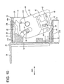
- FIG. 4 is a side view in section showing a state where a pressing portion is located on a pressable portion,
- FIG. 5 is a side view in section showing a state reached when the pressing portion moves over the pressable portion,
- FIG. 6 is a side view in section showing a state where the connecting operation of the two housings is completed,
- FIG. 7 is a plan view in section showing the state of FIG. 1,
- FIG. 8 is a plan view in section showing the state of FIG. 2,
- FIG. 9 is a plan view in section showing the state of FIG. 3,
- FIG. 10 is a plan view in section showing the state of FIG. 4,
- FIG. 11 is a plan view in section showing the state of FIG. 5,
- FIG. 12 is a plan view in section showing the state of FIG. 6, and
- FIG. 13 is a timing chart showing a correlation between the connected state of the two housings and electrically connected states.
- One preferred embodiment of the present invention is described with reference to FIGS. 1 to 13. A connector of this embodiment particularly is a connector for an airbag and is provided with one or more
first housings 10 and asecond housing 30 connectable with each other. The twohousings lever 40 rotatably or pivotably assembled at least partly into or onto thefirst housing 10. In the following description, sides of the first andsecond housings - The
second housing 30 is made e.g. of a synthetic resin and has areceptacle 31 having an open front surface as shown in FIG. 7. Thereceptacle 31 preferably substantially has the shape of a transversely long rectangle when viewed from front, and at least onepartition wall 31A substantially vertically extends in an intermediate position (preferably substantially in the transverse center) of thereceptacle 31. The interior of thereceptacle 31 is divided by the partition wall(s) 31A into a plurality (preferably a pair) of lateral (left and right) fitting recesses 31B into which thefirst housings 10 can be individually at least partly accommodated. It should be noted that only the rightfitting recess 31B when viewed from front is shown in FIGS. 7 to 12 and the construction of only thefitting recess 31B at the shown side is described below, however all the fitting recesses preferably have a similar or substantially same configuration. - In each
fitting recess 31B, one or more, preferably a plurality of secondterminal fittings 32 preferably in the form of tabs are transversely arranged substantially side by side at one or more stages, preferably at each of three (upper, middle or intermediate and lower) stages. One or more, preferably two second detectingterminals 39 are preferably transversely arranged substantially side by side at a side of the secondterminal fittings 32 at the upper stage near thepartition wall 31A. The second detectingterminals 39 preferably have the substantially same shape and/or substantially same projecting height as the secondterminal fittings 32. As described later, the second detectingterminals 39 are to be electrically connected with first detectingterminals 11 of thefirst housing 10 to close a connection detecting circuit for detecting or checking the connected state of the twohousings housings - A part of each of the second
terminal fittings 32 and the second detectingterminals 39 projects backward through aback wall 33 of thefitting recess 31B, is bent at an angle different from 0° or 180°, preferably substantially down substantially at right angle at an intermediate position, and has the bottom end thereof electrically is to be connected with a detecting device (such as a conductor path of an unillustrated printed circuit board thereof). One or more, preferably a pair ofprotection walls 34 project substantially backward from the rear ends of the (preferably substantially opposite) lateral (left and/or right) side(s) of thereceptacle 31, and the exposed parts of the respective secondterminal fittings 32 and second detectingterminals 39 are protected laterally (preferably from both left and right sides) by the one ormore protection walls 34. - Above each pair of second
terminal fittings 32 transversely adjacent to each other particularly at the upper and/or middle stages, a short cancelingmember 37 projects forward from theback wall 33 of thefitting recess 31B. As described later, the short cancelingmembers 37 at least partly enter a communication space S of thefirst housing 10 to thrust themselves between shortingterminals 12 and firstterminal fittings 13. - At least one cam pin 35 (as a preferred mating cam means) engageable with at least one later-described cam groove 41 (as a preferred cam means) of the lever 40 (as a preferred movable member) projects downward or inwardly preferably at a relatively transversely outward position of the ceiling surface of the
fitting recess 31B. Further, a disengagingprojection 38 preferably substantially in the form of a plate extending in forward and backward directions FBD projects downward or inwardly at a position of the ceiling surface of thefitting recess 31B near a side surface of thefitting recess 31B substantially opposite to thepartition wall 31A. - Likewise, a
lock projection 36 resiliently engageable with a later-describedlocking piece 42 of thelever 40 projects downward or inwardly preferably at a position of the ceiling surface of the fitting recess 3B near thepartition wall 31A. Thelock projection 36 has a front surface comprised of an upright surface extending downward or inwardly from the ceiling surface of thefitting recess 31B up to an intermediate position and a guidingsurface 36A extending substantially downward or inwardly from this intermediate position and inclined downward or inwardly toward the back, a substantially horizontal surface extending substantially backward from the rear end of the guidingsurface 36A, and alocking surface 36B extending substantially upright from the rear end of the horizontal surface toward the ceiling surface of thefitting recess 31B. - Each lever 40 (as the preferred movable member) is made e.g. of a synthetic resin and preferably is substantially "gate"-shaped as a whole. The
lever 40 includes a (preferably substantially plate-shaped) cam plate ormember 45, a (preferably substantially plate-shaped)posture correcting arm 47 arranged at a position substantially opposed to thecam plate 45, and anoperable portion 46 coupling the ends or end portions of thecam plate 45 and thearm 47. Thelever 40 preferably is to be at least partly accommodated into a later-describedaccommodating space 20 of thefirst housing 10, and movable (preferably rotatable or pivotable) between a standby position SBP (position of thelever 40 shown in FIG. 7) where thecam pin 35 can be received into the entrance of thecam groove 41 at the start of connecting the twohousings lever 40 shown in FIG. 12) where the twohousings lever 40 is based on a state where thelever 40 is at the connection ending position CEP as shown in FIG. 12. - The
cam groove 41 engageable with thecam pin 35 of thesecond housing 30 is arranged preferably on the outer surface (upper surface) of thecam plate 45. Thecam groove 41 is so formed by recessing the outer surface of thecam plate 45 as to locate the entrance thereof at or near an edge section (upper left side in FIG. 12) of the outer peripheral edge portion of thecam plate 45 preferably substantially opposite to theoperable portion 46 and to extend substantially toward the center of thecam plate 45. A (preferably substantially round)bearing hole 45A is formed near the back end of thecam groove 41. A bearingportion 22A of alever mounting surface 22 to be described later is at least partly fitted into thebearing hole 45A to movably (rotatably or pivotably) support thecam plate 45. Thus, as thelever 40 is operated (preferably rotated or pivoted), thecam pin 35 can be moved along thecam groove 41 to display a cam action and to connect and separate the twohousings - A temporarily-holding
resilient piece 48 for temporarily holding thelever 40 at the standby position SBP projects substantially backward in a resiliently deformable manner from a position near the entrance of thecam groove 41. A hookingportion 48A projecting obliquely outward toward the back is formed at or near the rear end of the temporarily-holdingresilient piece 48. A deformation space is defined between the temporarily-holdingresilient piece 48 and the outer peripheral edge of thecam plate 45, and the temporarily-holdingresilient piece 48 is so resiliently deformable with the entrance side of thecam groove 41 as a base end to move the hookingportion 48A inward. As a result, the temporarily-holdingresilient piece 48 prevents the movement (particularly the rotation) of thelever 40 towards or to the connection ending position CEP by the engagement of the hookingportion 48A with the front end of a receivingportion 20A projecting from an inner side surface of theaccommodating space 20 when thelever 40 is at the standby position SBP. During the movement (rotation) of thelever 40, the hookingportion 48A is disengaged from the front end of the receivingportion 20A by the disengagingprojection 38 of thesecond housing 30, thereby coming substantially into contact with the inner surface of the disengagingprojection 38 while the temporarily-holdingresilient piece 48 is resiliently deformed inward to permit the movement (rotation) of thelever 40. When thelever 40 substantially is at the connection ending position CEP, the hookingportion 48A is located substantially in an escaping space behind the disengagingprojection 38 and the receivingportion 20A, and the temporarily-holdingresilient piece 48 is resiliently at least partly restored. - The locking
piece 42 engageable with thelock projection 36 of thesecond housing 30 is arranged at a side of theoperable portion 46 in thecam plate 45. The lockingpiece 42 preferably is in the form of a cantilever formed particularly between a pair of straight slits extending substantially forward from the rear end of thecam plate 45, and is resiliently deformable upward and downward (directions substantially parallel to the thickness direction TD of the cam plate 45) with the front end thereof as a base end. - An area of the outer surface (upper surface) of the
cam plate 45 before the lockingpiece 42 is recessed to form alock escaping portion 49 for avoiding interference with thelock projection 36 during the movement (rotation) of thelever 40. A lockingprojection 51 substantially continuous with the rear end of thelock escaping portion 49 while preferably forming a step, and projecting upward or outward is provided at or near the base end of the lockingpiece 42. The front surface of the lockingprojection 51 forming the step is aslanted guiding surface 51A sloped up or outward toward the back as shown in FIG. 1, and the upper or outer surface of the lockingprojection 51 preferably substantially is flush with that of thecam plate 45. Further, the rear surface of the lockingprojection 51 is a substantiallyvertical locking surface 51B, and arecess 52 is formed behind this lockingsurface 51B. Thus, when the guidingsurface 51A of the lockingprojection 51 moves onto the guidingsurface 36A of thelock projection 36, the lockingpiece 42 is resiliently deformed downward or inward. When the lockingprojection 51 moves over thelock projection 36 and thelever 40 substantially reaches the connection ending position CEP, the lockingpiece 42 is at least partly restored to at least partly fit thelock projection 36 into therecess 52 and the lockingsurface 51B of the lockingprojection 51 is engaged with the lockingsurface 36B of thelock projection 36, whereby the movement (rotation) of thelever 40 towards or to the standby position SBP is prevented and the twohousings portion 53 is formed to straddle or bridge therecess 52 at the rear end of the lockingpiece 42, and the locked state by the engagement of the lockingsurface 36B of thelock projection 36 and the lockingsurface 51B of the lockingprojection 51 can be canceled by pressing the unlockingportion 53 down or inwardly. - As shown in FIG. 6, a
pressing portion 43 projects downward or inwardly at a position of the inner surface (lower surface) of thecam plate 45 substantially corresponding to the base end of the lockingpiece 42. The front surface of thepressing portion 43 is a substantially vertical surface unless the lockingpiece 42 is resiliently deformed, and the lower surface thereof is an inclined surface extending obliquely upward or outward toward the back from the bottom end of the front surface to the rear surface. The lower surface of thepressing portion 43 slides substantially along a movement path (rotational path) on the upper surface of a later-describedpressable portion 18B of theresilient arm 18 from behind as shown in FIG. 4 with the lockingpiece 42 resiliently deformed. The inclination of the lower surface of thepressing portion 43 is set such that theresilient arm 18 can be held in a specified (predetermined or predeterminable) resiliently deformed posture during this time. When thepressing portion 43 moves over thepressable portion 18B with theresilient arm 18 held in the specified (predetermined or predeterminable) resiliently deformed posture, theresilient arm 18 is substantially at least partly restored with thepressing portion 43 and thepressable portion 18B held in contact as shown in FIG. 5. With theresilient arm 18 restored, the first detecting terminals and the second detecting terminals are still kept in contact. - A
pre-pressing portion 44 projects downward or inward at a position of the inner surface of thecam plate 45 substantially corresponding to thelock escaping portion 49 as shown in FIG. 5. Thepre-pressing portion 44 is arranged to move substantially along the same movement path (rotational path) as thepressing portion 43 during the movement (rotation) of thelever 40. The front surface of thepre-pressing portion 44 is formed into an inclined surface sloped down or inwardly toward the back, the lower or inner surface thereof preferably is formed into a substantially horizontal surface substantially parallel to the lower or inner surface of thecam plate 45, and the rear surface thereof is a substantially vertical surface. A distance between thepre-pressing portion 44 and thepressing portion 43 preferably is set to be shorter than a dimension of thepressable portion 18B of theresilient arm 18 in forward and backward directions FBD. This can prevent thepressable portion 18B from at least partly entering between thepressing portion 43 and thepre-pressing portion 44. Thepre-pressing portion 44 slides from the inclined surface of thepressable portion 18B onto the upper surface of thepressable portion 18B along the movement path (rotational path) from behind before thepressing portion 43 presses thepressable portion 18B along the movement path (rotational path) during the movement (rotation) of thelever 40, whereby theresilient arm 18 is resiliently deformed downward or inwardly. When thelever 40 is further moved (rotated), thepressable portion 18B relatively moves from thepre-pressing portion 44 to thepressing portion 43. - The
first housing 10 is made e.g. of a synthetic resin and preferably substantially in the form of a block as a whole. Twofirst housings 10 particulraly are prepared in correspondence with the twofitting recesses 31B. As shown in FIG. 1, thelever 40 and aretainer 50 are assembled into eachfirst housing 10. Thefirst housing 10 shown in FIGS. 7 to 12 is the one to be at least partly accommodated into onefitting recess 31B of thesecond housing 30, and preferably has a substantially transversely symmetrical shape with the one to be at least partly accommodated into the otherfitting recess 31B. The latterfirst housing 10 is not described below. - One or more, preferably a plurality of
cavities 14 are formed to penetrate thefirst housing 10 in forward and backward directions FBD and arranged at one or more stages, preferably at three (upper, middle and lower) stages at positions substantially corresponding to the secondterminal fittings 32 at the time of connecting the twohousings terminal fittings 13 connected with ends of wires W are at least partly insertable into thesecavities 14 from an inserting side, preferably substantially from behind. When being inserted to a substantially proper insertion position, each first terminal fitting 13 is so held as not to come out preferably backward by being locked by a lockingportion 15 projecting from an inner surface of the correspondingcavity 14. As the twohousings terminal fittings 32 are at least partly inserted into the firstterminal fittings 13 and come into contact withresilient contact pieces 13A formed to be resiliently deformable by being folded back at the front edges of the upper surfaces of the firstterminal fittings 13 in the firstterminal fittings 13, whereby theterminal fittings - Likewise, one or more detecting terminal
accommodating portions 17 are formed to penetrate thefirst housing 10 substantially in forward and backward directions FBD at positions substantially corresponding to the second detectingterminals 39 at the time of connecting the twohousings accommodating portions 17 preferably are transversely juxtaposed with the cavities 14 (preferably at the upper stage), and the first detectingterminals 11 are at least partly insertable thereinto preferably substantially from behind. As the twohousings terminals 11 are electrically connected with the respective one or more second detectingterminals 39 of thesecond housing 30, thereby closing the connection detecting circuit for detecting the connected state of the twohousings terminals 11 is described later. - A
retainer mount hole 19 used to mount theretainer 50 is formed in the lateral (bottom) surface of thefirst housing 10. Theretainer mount hole 19 is formed to laterally (vertically) cross therespective cavities 14 at the one or more stages, preferably at the three stages, except the detecting terminalaccommodating portions 17. On the other hand,terminal insertion holes 50A are formed to penetrate theretainer 50 substantially in forward and backward directions FBD at positions substantially corresponding to therespective cavities 14 when theretainer 50 is at least partly mounted into theretainer mount hole 19. Further, theretainer 50 is movable between a partial locking position (as a preferred first position) where the insertion and withdrawal of the firstterminal fittings 13 through theterminal insertion holes 50A are permitted and a full locking position (as a preferred second position) where the firstterminal fittings 13 are locked so as not to come out backward (preferably doubly locked in cooperation with the locking portions 15) by engaging the front ends of the lateral (bottom) surfaces of theterminal insertion holes 50A with the rear ends of the firstterminal fittings 13. - The
accommodating space 20 for at least partly accommodating the lever 40 (as the preferred movable member) is so formed at or near an upper part of thefirst housing 10 as to have an open rear side. Theaccommodating space 20 preferably is formed between a coveringwall 21 constituting (at least part of) the upper or outer surface of thefirst housing 10 and alever mounting surface 22 facing the inner surface (lower surface) of this coveringwall 21, and thelever 40 is at least partly slid into this accommodating space 20 (preferably substantially from behind) while being held in a substantially horizontal posture. Theaccommodating space 20 substantially communicates with the insides of the detecting terminalaccommodating portions 17, and theresilient arm 18 is arranged in this communicating part. - The
resilient arm 18 preferably is in a substantially horizontal posture long in forward and backward directions FBD, acontact projection 18A projects downward or inward in an intermediate position (preferably substantially in the center) of the lower or inner surface of theresilient arm 18 with respect to forward and backward directions FBD, and thepressable portion 18B projects upward or outward (or in a substantially opposite direction than thecontact portion 18A) at or near the rear end (free end) of the upper or outer surface of theresilient arm 18. Theresilient arm 18 preferably is formed by forming a pair of slits in a wall surface between theaccommodating space 20 and the detecting terminalaccommodating portions 17 to extend substantially forward from the rear end and by making an area between both slits resiliently deformable upward and downward (or outward and inward) with the front end as a base end. Since the first detectingterminals 11 are at least partly accommodated in the detecting terminalaccommodating portions 17, they can be protected without being exposed to the outside. - The
pressable portion 18B is pressed or urged by thepressing portion 43 and thepre-pressing portion 44 of thelever 40. Thepressable portion 18B projects upward or outward from the rear end of theresilient arm 18, and a rear side of the upper surface thereof is formed into an inclined surface sloped down or inwardly toward the back. By operating the movable member (preferably by rotating the lever 40), thepre-pressing portion 44 and thepressing portion 43 of the movable member (lever 40) come into sliding contact with thepressable portion 18B along a movement path of the movable member (along an arcuate rotational path of the lever 40), whereby theresilient arm 18 is resiliently deformed downward or inwardly. At this time, the lever principle is utilized upon pressing thepressable portion 18B, so that an operating force necessary to resiliently deform theresilient arm 18 can be reduced. - The (preferably substantially cylindrical) bearing
portion 22A for rotatably or pivotably supporting thelever 40 is provided to project upward or outward from thelever mounting surface 22. In the process of mounting thelever 40, thecam plate 45 of thelever 40 moves over the bearingportion 22A while theaccommodating space 20 is widened by resiliently deforming the coveringwall 21 upward or outward. Thereafter, when thelever 40 reaches a substantially proper mount position, the bearingportion 22A is at least partly fitted into thebearing hole 45A of thecam plate 45 and thecam plate 45 is rotatably or pivotably supported and retained in theaccommodating space 20. The bearingportion 22A and thecam pin 35 are so arranged as to be aligned substantially on the same straight line along the connecting directions CD (or forward and backward directions FBD) of the twohousings housings first housing 10 preferably substantially coaxial with a central axis of the bearingportion 22A in vertical direction. This bearingportion 22A is at least partly fitted into an unillustrated bearing hole formed in the inner surface of theposture correcting arm 47 to rotatably or pivotably support theposture correcting arm 47. - One or more shorting-terminal
accommodating portions 16 for at least partly accommodating theshorting terminals 12 are formed to penetrate thefirst housing 10 substantially in forward and backward directions FBD above respective pairs ofcavities 14 adjacent to each other along width direction (preferably at the upper and middle stages). Each shorting-terminal accommodating portion 16 communicates with the insides of bothcavities 14 located adjacent thereto (e.g. therebelow), and this communication space S makes an opening in the front surface of thefirst housing 10. - Each shorting
terminal 12 includes amain body 12A that has a substantially gate-shaped cross section having an open bottom end, and two ormore tongue pieces 12B are resiliently deformably formed in themain body 12A to extend substantially forward by being folded back from the rear edge of the upper surface of themain body 12A. Thetongue pieces 12B are folded back to come into contact with the lateral (bottom) surface of the shorting-terminal accommodating portion 16, then inclined up toward the front, then inclined down to come into contact with the firstterminal fittings 13 through the communication space S, and consequently inclined up (or inclined at an angle different from 0° or 180°, preferably substantially transversely to the forward and backward directions FBD) again. Specifically, as shown in FIG. 2, the shortingterminal 12 resiliently touches one pair of adjacent firstterminal fittings 13 through the communication space S, thereby closing a shorting circuit for shorting (electrically connecting) these two or more firstterminal fittings 13. While the twohousings members 37 of thesecond housing 30 at least partly enter the communication spaces S from front to thrust themselves between the shortingterminals 12 and the corresponding ones or pairs of firstterminal fittings 13 as shown in FIG. 3, whereby the shorting circuits are held open (electrically unconnected state). It should be noted that the shorting circuits are set to be open after the first and secondterminal fittings - Each first detecting
terminal 11 is formed preferably by bending an electrically conductive metal plate into a specified (predetermined or predeterminable) shape and has amain body 11A preferably having a substantially U-shaped cross section having an open upper end. Acontact piece 11B is resiliently deformably formed to extend substantially forward in themain body 11A by being folded back at the rear edge of the bottom surface of themain body 11A. Thecontact piece 11B is substantially pointed or mountain-shaped, and the tip thereof serves as afirst contact point 11C. Thefirst contact point 11C is normally held substantially in contact with thecontact projection 18A of theresilient arm 18. An extending end of thecontact piece 11B is bent slightly upward, and the lower side of this bent portion serves as asecond contact point 11D. Thesecond contact point 11D comes substantially into contact with the second detectingterminal 39 when thecontact piece 11B is entirely resiliently deformed as thefirst contact point 11C is resiliently displaced downward or toward the other part orleg 11E of the first detectingterminal 11. Thus, as shown in FIG. 2, thepre-pressing portion 44 and thepressing portion 43 come into contact with thepressable portion 18B to resiliently deform theresilient arm 18 downward or inward as the operable member is operated (preferably as thelever 40 is rotated or pivoted); thefirst contact points 11C of the first detectingterminals 11 are displaced downward or inward to resiliently deform thecontact pieces 11B downward or inward (or toward the other part orleg 11E of the first detecting terminal 11) as thecontact projection 18A is displaced downward; and the second contact points 11D are displaced downward or inward (or toward the other part orleg 11E of the first detecting terminal 11) to come into contact with the second detectingterminals 39 as thecontact pieces 11B are resiliently deformed downward or inward. In this way, the first and second detectingterminals lever 40 is operated (rotated), the first detectingterminals 11 continue to touch the second detectingterminals 39 until the connecting operation of the twohousings terminals 11 are separated from the second detectingterminals 39 to hold the connection detecting circuit open (electrically unconnected state) when the connecting operation of the twohousings - FIG. 13 is a timing chart showing a correlation between the electrically connected states of the shorting circuits and the connection detecting circuit and the connected state of the two
housings housings housings - Next, functions of this embodiment thus constructed are described.
- Upon connecting the two
housings first housing 10 is lightly fitted into thefitting recess 31B to cause thecam pin 35 to enter the entrance of thecam groove 41 as shown in FIG. 7. Subsequently, as theoperable portion 46 of the operable member is operated (preferably theoperable portion 46 of thelever 40 is rotated or pivoted clockwise) in this state, thefirst housing 10 is pulled toward thesecond housing 30 by the cam action resulting from the engagement of thecam groove 41 and thecam pin 35. - At the initial stage of the operation or movement (preferably rotation) of the
lever 40, thepre-pressing portion 44 comes substantially into contact with thepressable portion 18B to resiliently deform theresilient arm 18 downward or inward and thecontact projection 18A is displaced downward or inward to displace thefirst contact points 11C of the first detectingterminals 11 downward as shown in FIG. 2. When the first detectingterminals 11 are resiliently deformed as the first contact points 11C are displaced downward or inward, the second contact points 11D are displaced downward or inward. Substantially in parallel with this, the leading ends of the second detectingterminals 39 come to positions below the first contact points 11C, whereby the second contact points 11D of the first detectingterminals 11 and the leading ends of the second detectingterminals 39 touch each other to be electrically connected. As a result, the connection detecting circuit is closed. Simultaneously, theresilient contact pieces 13A of the firstterminal fittings 13 touch or contact the secondterminal fittings 32 to electrically connect the firstterminal fittings 13 and the secondterminal fittings 32. - When the
lever 40 is successively operated (rotated), the lower or inner surface of thepre-pressing portion 44 slides on the upper or outer surface of thepressable portion 18B and the second detectingterminals 39 are at least partly inserted into the first detectingterminals 11 preferably while being held substantially in sliding contact with the second contact points 11D of the first detectingterminals 11 as shown in FIG. 3. On the other hand, the short cancelingmembers 37 of thesecond housing 30 are at least partly inserted into the communication spaces S from front to thrust themselves between the shortingterminals 12 and the firstterminal fittings 13, thereby cutting off the electrical connection to open the shorting circuits. In this way, since the firstterminal fittings 13 and the secondterminal fittings 32 are electrically connected when the shorting circuits are opened, the safety of the operation can be assured. It should be noted that thelock projection 36 of thesecond housing 30 enters thelock escaping portion 49 of thelever 40 as shown in FIG. 9, thereby avoiding the interference with thelever 40. - When the
lever 40 is further operated (rotated), the guidingsurface 36A of thelock projection 36 comes substantially into contact with the guidingsurface 51A of the lockingprojection 51 of the lockingpiece 42 as shown in FIG. 4, whereby the lockingpiece 42 starts being resiliently deformed downward or inward. Substantially in parallel with this, thepressable portion 18B relatively moves from thepre-pressing portion 44 to thepressing portion 43, but theresilient arm 18 is kept in a specified (predetermined or predeterminable) resiliently deformed posture. When thelever 40 is operated (rotated) to a position immediately before the connection ending position CEP, thepressable portion 18B moves over thepressing portion 43 and theresilient arm 18 is substantially resiliently (at least partly) restored once as shown in FIG. 5. In this restored posture, the second contact points 11D of the first detectingterminals 11 preferably are still kept in contact with the second detectingterminals 39. On the other hand, an angle of inclination of the lockingpiece 42 in the resiliently deformed posture is increased as thelever 40 is further operated (rotated), and thelocking piece 42 is still kept on thecontact projection 18A even immediately before the lockingprojection 51 moves over thelock projection 36. - When the
lever 40 substantially is at the connection ending position CEP, the lockingprojection 51 has already moved over thelock projection 36, the lockingpiece 42 has been resiliently at least partly restored to at least partly fit thelock projection 36 into therecess 52, and the lockingsurface 51B of the lockingprojection 51 and the lockingsurface 36B of thelock projection 36 have been engaged with each other, thereby locking the twohousings resilient arm 18 is (preferably substantially completely) restored to displace thecontact projection 18A upward, whereby thefirst contact points 11C of the first detectingterminals 11 are displaced upward or outward. As the first contact points 11C are displaced upward or outward, the second contact points 11D are displaced upward or outward away from the second detectingterminals 39 to open the connection detecting circuit. By the opening of the connection detecting circuit, the completely connected state of the twohousings - As described above, according to this embodiment, the first detecting
terminals 11 of thefirst housing 10 are held in contact with the second detectingterminals 39 of thesecond housing 30 until the connecting operation of the twohousings terminals 11 are separated from the second detectingterminals 39 when the connecting operation is completed. Thus, the connected state of the twohousings terminals 12 are separated from the firstterminal fittings 13 after the first and secondterminal fittings terminal fittings 13 are electrically connected with the secondterminal fittings 32 when being freed from the shorted state and, accordingly, the safety of the operation can be assured. Furthermore, the first detectingterminals 11 preferably can be so protected as not to be exposed to the outside since the first detectingterminals 11 are at least partly accommodated in the detecting terminalaccommodating portions 17 and theresilient arm 18 is formed by cutting part of the inner wall forming the detecting terminalaccommodating portions 17. Further, since the first detectingterminals 11 preferably are resiliently deformed utilizing the lever principle by providing thepressable portion 18B at or near the free end of theresilient arm 18 and/or providing thecontact projection 18A in an intermediate position (preferably substantially in the longitudinal center) of theresilient arm 18, an operation force exerted upon pressing thepressable portion 18B can be reduced. - Accordingly, to electrically detect a connected state of at least two housings, one or more
first housings 10 and asecond housing 30 are provided to be connectable with each other in a connector, wherein secondterminal fittings 32, one or more second detectingterminals 39 and one or more short cancelingmembers 37 are arranged in thesecond housing 30, and one ormore shorting terminals 12 for shorting corresponding two or more (preferably pairs of) first terminal fittings, at least oneresilient arm 18 resiliently deformable as the twohousings terminals 11 resiliently deformable as theresilient arm 18 is resiliently deformed to touch the second detectingterminals 39, thereby detecting the connected state are arranged in eachfirst housing 10. Theresilient arm 18 is held resiliently deformed and the first detectingterminals 11 are held in contact with the second detectingterminals 39 until a connecting operation of the twohousings resilient arm 18 is resiliently at least partly restored and the first detectingterminals 11 are separated from the second detectingterminals 32 when the connecting operation is completed. - The present invention is not limited to the above described and illustrated embodiment. For example, the following embodiments are also embraced by the technical scope of the present invention as defined by the claims. Beside the following embodiments, various changes can be made without departing from the scope and spirit of the present invention as defined by the claims.
- (1) Although the
lever 40 is assembled into thefirst housing 10 according to the foregoing embodiment, thelever 40 may be assembled into thesecond housing 30 according to the present invention. - (2) Although the
resilient arm 18 is resiliently deformed by operating (rotating) thelever 40 in the foregoing embodiment, it is sufficient according to the present invention for theresilient arm 18 to be resiliently deformable as the twohousings resilient arm 18 may be resiliently deformed by the contact with the inner surface of thefitting recess 31B of thesecond housing 30. - (3) Although the lever-type connector in which the two
housings lever 40 is illustrated in the foregoing embodiment, the connector needs not necessarily be a lever-type connector and may utilize a lock arm according to the present invention. - (4) Furthermore, any other operable member displaying a cam action other than a rotatable or pivotable lever such as a slider movable along a substantially linear path can be used in connection with the invention.
-
- 10 ...
- first housing
- 11 ...
- first detecting terminal
- 12 ...
- shorting terminal
- 13 ...
- first terminal fitting
- 17 ...
- detecting terminal accommodating portion
- 18 ...
- resilient arm
- 18A ...
- contact projection
- 18B ...
- pressable portion
- 30 ...
- second housing
- 32 ...
- second terminal fitting
- 35 ...
- cam pin
- 36 ...
- lock projection
- 37 ...
- short canceling member
- 39 ...
- second detecting terminal
- 40 ...
- lever
- 41 ...
- cam groove
- 42 ...
- locking piece
- 43 ...
- pressing portion
- 44 ...
- pre-pressing portion
Claims (10)
- A connector, comprising a first and a second housings (10, 30) connectable with each other, wherein:second terminal fittings (32), at least one second detecting terminal (39) and a short canceling member (37) are arranged in or on the second housing (30),a plurality of first terminal fittings (13) that touch or contact the second terminal fittings (32) and are arranged at adjacent positions, at least one shorting terminal (12) for shorting at least part of the first terminal fittings (13) by touching or contacting the first terminal fittings (13), a resilient arm (18) resiliently deformable as the first and second housings (10, 30) are connected, and at least one first detecting terminal (11) that is resiliently deformable as the resilient arm (18) is resiliently deformed and touches the second detecting terminal (39) to detect the connected state of the first and second housings (10, 30) are arranged in the first housing (10), andthe resilient arm (18) is to be held resiliently deformed and the first detecting terminal (11) is to be held in contact with the second detecting terminal (39) until a connecting operation is completed,the shorting terminal (12) is to be held separated from the first terminal fitting (13) by means of the short canceling member (37) as the connecting operation progresses, andthe resilient arm (18) is to be resiliently at least partly restored and the first detecting terminal (11) is to be separated from the second detecting terminal (39) when the connecting operation is substantially completed.
- A connector according to claim 1, wherein the shorting terminal (12) is to be held separated from the first terminal fitting (13) after the short canceling member (37) thrusts itself at least partly between the shorting terminal (12) and the first terminal fittings (13) as the connecting operation progresses.
- A connector according to one or more of the preceding claims, wherein the shorting terminal (12) is separated from the first terminal fittings (13) after the first and second terminal fittings (13, 32) touch or contact each other.
- A connector according to one or more of the preceding claims, wherein a movable member (40) operable to connect and separate the connector housings (10, 30) or to assist the connection and separation thereof by means of a cam action is provided on one of the connector housings (10, 30).
- A connector according to claim 4, wherein the operable member (40) formed with at least one cam means (41) is movably assembled into the first housing (10) at a side of the resilient arm (18) substantially opposite to the first detecting terminal (11), a mating cam means (35) which can cooperate with the cam means (41) is formed in the second housing (30).
- A connector according to claim 4 or 5, wherein at least one pressing portion (43) capable of pressing the resilient arm (18) is formed at a portion of the movable member (40) substantially facing the resilient arm (18), and
wherein the pressing portion (43) presses the resilient arm (18) to hold the resilient arm (18) resiliently deformed during the operation of the movable member (40) while stopping pressing the resilient arm (18) to resiliently at least partly restore the resilient arm (18) when the connecting operation is substantially completed. - A connector according to claim 6, wherein the resilient arm (18) is formed into a cantilever resiliently deformable with a side thereof toward a connecting surface as a base end by cutting part of an inner wall of the detecting terminal accommodating portion (17) for at least partly accommodating the first detecting terminal (11) along a connecting direction (CD) of the first and second housings (10, 30).
- A connector according to claim 6 or 7, wherein a pressable portion (18B) to be touched by the pressing portion (43) is formed at or near a free end of the resilient arm (18), and a contact projection (18A) that comes into contact with the first detecting terminal (11) is formed at an intermediate position, preferably substantially at a longitudinal middle position of the resilient arm (18).
- A method of controlling the assembly of a connector comprising a first and a second housings (10, 30) connectable with each other, comprising the following steps:arranging in or on the second housing (30):second terminal fittings (32),at least one second detecting terminal (39) and a short canceling member (37),arranging in or on the first housing (10):a plurality of first terminal fittings (13) that touch or contact the second terminal fittings (32) and are arranged at adjacent positions,at least one shorting terminal (12) for shorting at least part of the first terminal fittings (13) by touching or contacting the first terminal fittings (13),a resilient arm (18) resiliently deformable as the first and second housings (10, 30) are connected, andat least one first detecting terminal (11) that is resiliently deformable as the resilient arm (18) is resiliently deformed and touches the second detecting terminal (39) to detect the connected state of the first and second housings (10, 30), andthe resilient arm (18) is to be held resiliently deformed and the first detecting terminal (11) is to be held in contact with the second detecting terminal (39) until a connecting operation is completed,as the connecting operation progresses: holding the shorting terminal (12) separated from the first terminal fitting (13) by means of the short canceling member (37), andwhen the connecting operation is substantially completed: resiliently at least partly restoring the resilient arm (18) and separating the first detecting terminal (11) from the second detecting terminal (39).
- A method according to claim 9, wherein the shorting terminal (12) is held separated from the first terminal fitting (13) after the short canceling member (37) thrusts itself at least partly between the shorting terminal (12) and the first terminal fittings (13) as the connecting operation progresses.
Applications Claiming Priority (1)
| Application Number | Priority Date | Filing Date | Title |
|---|---|---|---|
| JP2005372234A JP4577209B2 (en) | 2005-12-26 | 2005-12-26 | connector |
Publications (2)
| Publication Number | Publication Date |
|---|---|
| EP1801931A1 true EP1801931A1 (en) | 2007-06-27 |
| EP1801931B1 EP1801931B1 (en) | 2010-08-18 |
Family
ID=37865630
Family Applications (1)
| Application Number | Title | Priority Date | Filing Date |
|---|---|---|---|
| EP06026216A Expired - Fee Related EP1801931B1 (en) | 2005-12-26 | 2006-12-18 | A connector and a method for controlling the assembly thereof |
Country Status (5)
| Country | Link |
|---|---|
| US (1) | US7294015B2 (en) |
| EP (1) | EP1801931B1 (en) |
| JP (1) | JP4577209B2 (en) |
| CN (1) | CN100536251C (en) |
| DE (1) | DE602006016227D1 (en) |
Cited By (1)
| Publication number | Priority date | Publication date | Assignee | Title |
|---|---|---|---|---|
| CN104512457A (en) * | 2013-10-08 | 2015-04-15 | 现代摩比斯株式会社 | Power pack device for MDPs |
Families Citing this family (15)
| Publication number | Priority date | Publication date | Assignee | Title |
|---|---|---|---|---|
| JP4985326B2 (en) * | 2007-11-01 | 2012-07-25 | 住友電装株式会社 | connector |
| JP5223777B2 (en) * | 2009-05-27 | 2013-06-26 | 住友電装株式会社 | connector |
| JP5329330B2 (en) * | 2009-07-22 | 2013-10-30 | 日本航空電子工業株式会社 | Connector assembly |
| JP5817457B2 (en) * | 2011-11-18 | 2015-11-18 | 住友電装株式会社 | connector |
| JP2015060628A (en) * | 2013-09-17 | 2015-03-30 | 住友電装株式会社 | Connector |
| JP6571910B2 (en) * | 2013-10-17 | 2019-09-04 | 矢崎総業株式会社 | Lever type connector |
| JP2015099683A (en) * | 2013-11-19 | 2015-05-28 | 住友電装株式会社 | Connector |
| JP6172207B2 (en) * | 2015-04-24 | 2017-08-02 | 住友電装株式会社 | connector |
| JP6569131B2 (en) * | 2016-04-26 | 2019-09-04 | 株式会社オートネットワーク技術研究所 | Electrical connection device having fitting detection function |
| JP6816668B2 (en) * | 2017-07-11 | 2021-01-20 | 株式会社オートネットワーク技術研究所 | connector |
| JP6840640B2 (en) * | 2017-08-18 | 2021-03-10 | 日本航空電子工業株式会社 | Connector device |
| JP7091749B2 (en) * | 2018-03-20 | 2022-06-28 | 住友電装株式会社 | connector |
| JP2020047363A (en) * | 2018-09-14 | 2020-03-26 | 住友電装株式会社 | connector |
| JP7232407B2 (en) * | 2019-08-09 | 2023-03-03 | 住友電装株式会社 | connector |
| JP7437614B2 (en) * | 2020-08-26 | 2024-02-26 | 住友電装株式会社 | connector |
Citations (5)
| Publication number | Priority date | Publication date | Assignee | Title |
|---|---|---|---|---|
| US5277608A (en) | 1992-04-16 | 1994-01-11 | The Whitaker Corporation | Electrical connector |
| EP0751591A2 (en) * | 1995-06-29 | 1997-01-02 | Sumitomo Wiring Systems, Ltd. | Engagement detection connector |
| US5647754A (en) * | 1994-07-08 | 1997-07-15 | The Whitaker Corporation | Short-circuit connector |
| EP0822620A1 (en) * | 1996-07-25 | 1998-02-04 | Sumitomo Wiring Systems, Ltd. | A short-circuiting terminal fitting and a connector comprising such a short-circuiting terminal fitting |
| JP2003086301A (en) | 2001-09-07 | 2003-03-20 | Sumitomo Wiring Syst Ltd | Lever type connector |
Family Cites Families (7)
| Publication number | Priority date | Publication date | Assignee | Title |
|---|---|---|---|---|
| US5128830A (en) * | 1990-07-02 | 1992-07-07 | Digital Equipment Corporation | Integrated installation assembly with self aligning connector |
| US5775939A (en) | 1996-10-08 | 1998-07-07 | Lucent Technologies Inc. | Interface assembly for peripheral accessories |
| JP3415008B2 (en) * | 1997-11-12 | 2003-06-09 | 住友電装株式会社 | connector |
| JP3508015B2 (en) * | 1999-12-03 | 2004-03-22 | 住友電装株式会社 | connector |
| JP2001196134A (en) * | 2000-01-14 | 2001-07-19 | Sumitomo Wiring Syst Ltd | Fitting detection connector and fitting detection terminal |
| JP3745581B2 (en) * | 2000-04-03 | 2006-02-15 | 矢崎総業株式会社 | Half mating detection connector |
| JP4678333B2 (en) * | 2005-09-29 | 2011-04-27 | 住友電装株式会社 | Lever type connector |
-
2005
- 2005-12-26 JP JP2005372234A patent/JP4577209B2/en not_active Expired - Fee Related
-
2006
- 2006-12-18 EP EP06026216A patent/EP1801931B1/en not_active Expired - Fee Related
- 2006-12-18 DE DE602006016227T patent/DE602006016227D1/en active Active
- 2006-12-22 US US11/644,796 patent/US7294015B2/en active Active
- 2006-12-26 CN CNB2006101724063A patent/CN100536251C/en not_active Expired - Fee Related
Patent Citations (6)
| Publication number | Priority date | Publication date | Assignee | Title |
|---|---|---|---|---|
| US5277608A (en) | 1992-04-16 | 1994-01-11 | The Whitaker Corporation | Electrical connector |
| US5647754A (en) * | 1994-07-08 | 1997-07-15 | The Whitaker Corporation | Short-circuit connector |
| EP0751591A2 (en) * | 1995-06-29 | 1997-01-02 | Sumitomo Wiring Systems, Ltd. | Engagement detection connector |
| EP0822620A1 (en) * | 1996-07-25 | 1998-02-04 | Sumitomo Wiring Systems, Ltd. | A short-circuiting terminal fitting and a connector comprising such a short-circuiting terminal fitting |
| US5863216A (en) * | 1996-07-25 | 1999-01-26 | Sumitomo Wiring Systems, Ltd. | Short-circuiting terminal fitting and connector therefor |
| JP2003086301A (en) | 2001-09-07 | 2003-03-20 | Sumitomo Wiring Syst Ltd | Lever type connector |
Cited By (2)
| Publication number | Priority date | Publication date | Assignee | Title |
|---|---|---|---|---|
| CN104512457A (en) * | 2013-10-08 | 2015-04-15 | 现代摩比斯株式会社 | Power pack device for MDPs |
| CN104512457B (en) * | 2013-10-08 | 2017-04-12 | 现代摩比斯株式会社 | Power pack device for MDPs |
Also Published As
| Publication number | Publication date |
|---|---|
| EP1801931B1 (en) | 2010-08-18 |
| CN100536251C (en) | 2009-09-02 |
| DE602006016227D1 (en) | 2010-09-30 |
| US7294015B2 (en) | 2007-11-13 |
| CN101017946A (en) | 2007-08-15 |
| JP2007173164A (en) | 2007-07-05 |
| JP4577209B2 (en) | 2010-11-10 |
| US20070149041A1 (en) | 2007-06-28 |
Similar Documents
| Publication | Publication Date | Title |
|---|---|---|
| EP1801931B1 (en) | A connector and a method for controlling the assembly thereof | |
| US7445491B2 (en) | Connector and a connector assembly | |
| EP1689041B1 (en) | A connector, a connector testing apparatus and method | |
| EP2020706B1 (en) | A connector, connector assembly and connection method | |
| KR100740853B1 (en) | A connector and a method of assembling it | |
| US7287993B2 (en) | Connector having a movable member | |
| EP1986288B1 (en) | A shorting terminal, a connector and an assembling method therefor | |
| US7404730B2 (en) | Connector, connector assembly and a detection terminal | |
| US8449319B2 (en) | Connector | |
| US20130130539A1 (en) | Connector | |
| EP1801925B1 (en) | A connector | |
| US6805564B2 (en) | Split-type connector and connector assembly | |
| EP0871253B1 (en) | Lock detection connector | |
| JP2001015213A (en) | Semi-fitting detection connector | |
| JP2006216375A (en) | Method for detecting lock of connector, and the connector | |
| CN107785730B (en) | Electrical connector for flat conductor | |
| JP2001176595A (en) | Connector | |
| JP2002025704A (en) | Connector |
Legal Events
| Date | Code | Title | Description |
|---|---|---|---|
| PUAI | Public reference made under article 153(3) epc to a published international application that has entered the european phase |
Free format text: ORIGINAL CODE: 0009012 |
|
| 17P | Request for examination filed |
Effective date: 20061228 |
|
| AK | Designated contracting states |
Kind code of ref document: A1 Designated state(s): AT BE BG CH CY CZ DE DK EE ES FI FR GB GR HU IE IS IT LI LT LU LV MC NL PL PT RO SE SI SK TR |
|
| AX | Request for extension of the european patent |
Extension state: AL BA HR MK YU |
|
| AKX | Designation fees paid | ||
| RBV | Designated contracting states (corrected) |
Designated state(s): DE FR |
|
| GRAP | Despatch of communication of intention to grant a patent |
Free format text: ORIGINAL CODE: EPIDOSNIGR1 |
|
| GRAS | Grant fee paid |
Free format text: ORIGINAL CODE: EPIDOSNIGR3 |
|
| GRAA | (expected) grant |
Free format text: ORIGINAL CODE: 0009210 |
|
| RIN1 | Information on inventor provided before grant (corrected) |
Inventor name: FUJII, MASAYASU Inventor name: SAKURAI, TOSHIKAZU |
|
| AK | Designated contracting states |
Kind code of ref document: B1 Designated state(s): DE FR |
|
| REF | Corresponds to: |
Ref document number: 602006016227 Country of ref document: DE Date of ref document: 20100930 Kind code of ref document: P |
|
| PLBE | No opposition filed within time limit |
Free format text: ORIGINAL CODE: 0009261 |
|
| STAA | Information on the status of an ep patent application or granted ep patent |
Free format text: STATUS: NO OPPOSITION FILED WITHIN TIME LIMIT |
|
| 26N | No opposition filed |
Effective date: 20110519 |
|
| REG | Reference to a national code |
Ref country code: DE Ref legal event code: R097 Ref document number: 602006016227 Country of ref document: DE Effective date: 20110519 |
|
| REG | Reference to a national code |
Ref country code: FR Ref legal event code: PLFP Year of fee payment: 10 |
|
| REG | Reference to a national code |
Ref country code: FR Ref legal event code: PLFP Year of fee payment: 11 |
|
| REG | Reference to a national code |
Ref country code: DE Ref legal event code: R084 Ref document number: 602006016227 Country of ref document: DE |
|
| REG | Reference to a national code |
Ref country code: FR Ref legal event code: PLFP Year of fee payment: 12 |
|
| PGFP | Annual fee paid to national office [announced via postgrant information from national office to epo] |
Ref country code: DE Payment date: 20191203 Year of fee payment: 14 |
|
| PGFP | Annual fee paid to national office [announced via postgrant information from national office to epo] |
Ref country code: FR Payment date: 20191115 Year of fee payment: 14 |
|
| REG | Reference to a national code |
Ref country code: DE Ref legal event code: R119 Ref document number: 602006016227 Country of ref document: DE |
|
| PG25 | Lapsed in a contracting state [announced via postgrant information from national office to epo] |
Ref country code: FR Free format text: LAPSE BECAUSE OF NON-PAYMENT OF DUE FEES Effective date: 20201231 |
|
| PG25 | Lapsed in a contracting state [announced via postgrant information from national office to epo] |
Ref country code: DE Free format text: LAPSE BECAUSE OF NON-PAYMENT OF DUE FEES Effective date: 20210701 |