EP1801786A1 - An audio system with varying time delay and a method for processing audio signals. - Google Patents
An audio system with varying time delay and a method for processing audio signals. Download PDFInfo
- Publication number
- EP1801786A1 EP1801786A1 EP05112449A EP05112449A EP1801786A1 EP 1801786 A1 EP1801786 A1 EP 1801786A1 EP 05112449 A EP05112449 A EP 05112449A EP 05112449 A EP05112449 A EP 05112449A EP 1801786 A1 EP1801786 A1 EP 1801786A1
- Authority
- EP
- European Patent Office
- Prior art keywords
- signal
- processed
- processing
- time delay
- digital
- Prior art date
- Legal status (The legal status is an assumption and is not a legal conclusion. Google has not performed a legal analysis and makes no representation as to the accuracy of the status listed.)
- Granted
Links
Images


Classifications
-
- G—PHYSICS
- G10—MUSICAL INSTRUMENTS; ACOUSTICS
- G10L—SPEECH ANALYSIS TECHNIQUES OR SPEECH SYNTHESIS; SPEECH RECOGNITION; SPEECH OR VOICE PROCESSING TECHNIQUES; SPEECH OR AUDIO CODING OR DECODING
- G10L21/00—Speech or voice signal processing techniques to produce another audible or non-audible signal, e.g. visual or tactile, in order to modify its quality or its intelligibility
- G10L21/02—Speech enhancement, e.g. noise reduction or echo cancellation
Definitions
- the invention regards audio systems as used in hearing aids, headsets and other devices wherein an environmental audio signal is processed and continually served at one or more listeners.
- the processing delay should in general be lower than 10 milliseconds. This time is based on average ratings and rather large deviations exist depending on degree of: amplification, incoming sound signal, type of sound processing and individual differences between people. The range of acceptable values may be roughly 3 to 40 milliseconds depending on such factors.
- noise reduction oriented processing which is often based on block processing, and if the system is only allowed to impose a short delay, only very limited block length can be used leading to poorer performance.
- the filterbanks provide a number of bands, which is a programmable parameter.
- the invention provides a method of audio processing and an audio device which offers a solution to this problem.
- a method for processing audio signals whereby an audio signal is captured, digitized and processed in the digital domain by a digital signal processing unit or DSP, and where a processed output signal from the digital signal processing unit is adapted to a transducer and served at the transducer for providing a sensation of sound.
- a digital signal processing unit or DSP digital signal processing unit
- At least two different digital algorithms are available within the digital processing unit which delivers each their processed signal having each their non identical time delay and the algorithm or output signal from the algorithm which provides the most rewarding sound signal for the user is automatically chosen.
- a hearing aid system which makes use of the method according to the invention can vary the delay in steps (or continuously) in addition to the well known variations such as fast anti-feedback and slow anti-feedback, detection of speech or absence of speech, etc.
- a short delay may for instance be desirable when a high speech to noise ratio is present, whereas a long delay may be useful for the hearing impaired in situations where a high background noise level is present and where noise reduction oriented processing is imperative.
- a long delay could also be desirable in cases where the demands on the anti-feedback system are unusually high, since a large throughput delay makes it possible to increase the performance of the anti-feedback system.
- the left and right hearing aids should have their delays synchronized by means of a communication link between the hearing aids.
- the input signal is initially analysed and based on results thereof a choice is made as to which algorithm and accompanying time delay should be performed in order to provide the most rewarding output signal for the user, whereby an according decision signal from an analyse block is served at the DSP unit in order to realize the chosen algorithm.
- the DSP unit will only perform one of the possible algorithms, and this will aid to save power. This is most important in portable systems like hearing aids and headsets.
- the input signal is analysed in the DSP unit, and at least two processing algorithms are performed on the input signal, and the possible effect of the different algorithms in terms of user benefit is assessed and the effect of the time delay of each algorithm is taken in account in order to determine which algorithm will provide the most rewarding processed signal, and a corresponding decision signal is served at a decision box in order to choose the corresponding output from the processing algorithm.
- the signal produced by each of the different algorithms will be available immediately when desired as output and also the effect of the performed algorithm may be analysed on the resulting output signal.
- a time alignment between a current processed signal and a desired processed signal is provided by introducing a time delay in the processed signal having the smallest time delay of the two whereafter fading from a current signal to a desired signals is performed. In this way it becomes possible to change from the output of algorithms with different time delay without audible side effects.
- an audio system comprising means for capturing an audio signal, mans for digitizing the audio signal and a digital signal processing unit or DSP for processing in the digital domain of the audio signal.
- a processed output signal from the DSP unit is adapted to a transducer and served at the output transducer for providing a sensation of sound.
- the DSP unit is provided with means for performing at least two different digital algorithms which delivers each their processed signal having each their non identical time delay and further means are provided for choosing the most rewarding sound signal for the user.
- Such a system is capable of performing automatic choice of audio processing algorithm whereby the delay realized by the chosen algorithm is reflected in the output signal and where the choice is performed based on time delay which is tolerable under the given circumstances.
- Fig. 1 illustrates a simplified example of a hearing aid which embodies an example of the method according to the invention.
- a diagram of the signal path in a hearing aid is shown, whereby one or more microphones 1 are arranged to pick up environmental sounds.
- other sound signals may be transmitted through the signal path, such as telecoil signals or other wireless or wired audio signal as well known in conventional hearing aids.
- the incoming signals 2 are digitized in the usual way (not shown in the figure) and routed to a digital signal processing unit (DSP) 3.
- DSP digital signal processing unit
- a usual amplification and noise damping process is performed on the incoming signal as is usual in hearing aids.
- the method according to the invention allows two or more different algorithms to be performed on the audio signal in the DSP unit and thus delivering two or more output signals, illustrated in fig. 1 by S 1 , S 2 and S 3 .
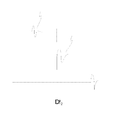
- the algorithms have each their time delay Dt 1 , Dt 2 and Dt 3 as displayed in fig. 2.
- the DSP unit will analyze the input signal 2 in order to determine which of the output signals S 1 , S 2 and S 3 will provide the most rewarding signal for the user.
- the result of this is a control signal 4, which will determine which of the signals S 1 , S 2 and S 3 are to be presented to the user.
- various signal parameters are determined and compared, and based on the size of the parameters a choice of output signal is performed.
- the choice is made as a compromise which balances the harming effects of long delays and the benefits of extensive signal processing. If a short time delay is wished, a simple or reduced signal processing is performed in the DSP unit, and in cases where longer time delays may be tolerated, a more complex algorithm may be employed which may provide other advantages, outbalancing the drawback of the longer time delay.
- the control signal 4 is served at a choice box 5 wherein the choice of output signal is performed.
- a choice box 5 it is shown as if a simple switch is used to choose between the presented output signals, but such a solution will cause very annoying side effects for the user, and is thus not very useful in real life, but it is shown for illustrative purposes.
- the chosen output signal 6 is routed to an output stage 7 wherein among other the signal is adapted to the output transducer 8.
- the signal is served at the output transducer 8 which feeds an output signal to the user in a form perceivable as sound.
- an electrode provides the output in the form of electrical signals to the cochlear of the user.
- the data stream When the delay is changing from a longer to a shorter delay eg changing from the signal S 2 to the signal S 1 the data stream will be affected by a data loss representing the time difference between Dt 2 and Dt 1 .
- an audio event will result in a signal event A1 representative thereof in S 1 which will arrive at choice box 5 Dt 1 milliseconds after the signal reached the microphones 1.
- the same audio event will result in a signal event A2 representative thereof in S 2 which will arrive at choice box 5 Dt 2 milliseconds after the audio signal reached the microphones 1.
- the signal events A1 and A2 will represent the same audio event, but will be processed according to each their algorithm in the DSP unit 3.
- the time difference between Dt 1 and Dt 2 could be in the range of 10 to 4 milliseconds.
- a suitable time window which as an example could be in the order of 5-10 milliseconds both S 2 and S 1 will generate output data and the data which are fed to the receiver of the hearing aid will be calculated as an interpolation between the two signals in order to avoid clicks or other artefacts.
- the receiver signal is based on the long delay signal S 2 , and this is gradually changed so that at the end of the time window, the receiver signal is based on the S 1 signal with the short delay Dt 1 .
- a possible first step is to delay the signal S 1 , the delay being equal to the time difference between Dt 1 and Dt 2 , such that the delayed S 1 signal has the delay time of the signal S 2 namely Dt 2 . This will ensure that the S 1 and S 2 signals are aligned with respect to time.
- the next step is to interpolate between the S 2 signal and the delayed version of the S 1 signal. This interpolation provides a smooth change between synchronous signals based on two different processing schemes each associated with the respective processing delays of Dt 1 and Dt 2 .
- This interpolation takes place in a time frame which could be in the range between 1 and 30 milliseconds.
- the output signal 6 is changed from the delayed version of the S 1 signal and to the S 1 signal itself. This is done through a transition time which could be 0.2 milliseconds during which the delayed S 1 signal is gradually attenuated and the S 1 signal is gradually increased in amplitude from almost zero and until the specified value is reached.
- a possible first step could be to change from the S 1 signal and to a delayed version of the S 1 signal - the delay being equal to the time difference between S 1 and S 2 signals. This could be in the range from 4 to 6 milliseconds. This is done through a transition time which could be 0.2 milliseconds during which the S 1 signal is gradually attenuated and the delayed version of the S 1 signal is gradually increased in amplitude from almost zero and until the specified value is reached.
- the second step is that an interpolation between the S 2 signal and a delayed version of the S 1 signal is performed.
- This interpolation provides a smooth change between synchronous signals based on two different processing schemes each associated with the respective processing delay of Dt 1 and Dt 2 .
- This interpolation takes place in a time frame which could be 3 milliseconds.
- the signal transitions according to the present invention may be postponed until a time where only a weak input signal is present in the input line 2. In this way the possibility of audible artefacts may be reduced.
- the signal transitions according to the present invention may be postponed until a time where a weak signal is present immediately after a strong signal. In this way the possibility of audible artefacts may be further reduced through time domain masking effects known to be present in human hearing.
- a further embodiment of the invention is schematically displayed.
- the decision regarding delay time is based on filterbank data as well as on data from the DSP.
- the DSP is capable of several levels of processing depending on the allowable delay.
- the unit performs two processing algorithms during transition from one to another type of algorithm. This is explained in detail in the following.
- the bloc 10 is a filterbank which will split the input signal 2 into a number of signals each representing a limited frequency span. These signals are transferred to a signal processing unit through a signal path 17 and also the signals are passed to a signal analysis unit 12 through a path 11.
- the analysis unit 12 further receives data 14, 15, 16 from the DSP unit 3, relating to the signal processing such as status of antifeedback, voice activity detection, music detection or other important features relating to the signal processing. Based on these data the analysis unit 12 determines which signal processing algorithm should be performed and feeds a signal 13 accordingly to the DSP unit 3. The unit 3 will perform the chosen algorithm until a new signal value 13 is presented. At most times the DSP 3 only performs one algorithm at a time.
Landscapes
- Engineering & Computer Science (AREA)
- Computational Linguistics (AREA)
- Quality & Reliability (AREA)
- Signal Processing (AREA)
- Health & Medical Sciences (AREA)
- Audiology, Speech & Language Pathology (AREA)
- Human Computer Interaction (AREA)
- Physics & Mathematics (AREA)
- Acoustics & Sound (AREA)
- Multimedia (AREA)
- Stereophonic System (AREA)
Abstract
Description
- The invention regards audio systems as used in hearing aids, headsets and other devices wherein an environmental audio signal is processed and continually served at one or more listeners.
- It is well documented that the delay, introduced by digital processing in modern audio systems, can lead to a range of disturbing effects experienced by the user. The processing delay should in general be lower than 10 milliseconds. This time is based on average ratings and rather large deviations exist depending on degree of: amplification, incoming sound signal, type of sound processing and individual differences between people. The range of acceptable values may be roughly 3 to 40 milliseconds depending on such factors.
- While a short delay is desirable in order to limit the disturbing effects experienced by the user, (poor sound quality, difficulty in locating direction of sound source) when a short delay is specified it severely limits the processing capabilities of a given audio system.
- Hence, the more advanced processing used in the system, the longer the delay will inevitably be. One example is noise reduction oriented processing which is often based on block processing, and if the system is only allowed to impose a short delay, only very limited block length can be used leading to poorer performance.
- In state of the art audio systems a certain fixed processing delay is imposed. This delay is a compromise between the risk of subjectively experienced problems and the processing capabilities.
- In connection with audio devices of the hearing aid type there has been a trend in recent years towards more open hearing aids, i.e. instruments with large vent diameters. Such open instruments may be particularly sensitive to the delay introduced by the audio processing. At the same time there is a push for more time consuming signal processing features enhancing the wanted signal (typically a speech signal).
- According to the disclosure of
US 20020122562 A1 , there exists many possible tradeoffs between the number of bands, the quality of the bands, filterbank delay and power consumption. In general, increasing the number or quality of the filterbank bands leads to increased delay and power usage. For a fixed delay, the number of bands and quality of bands are inversely related to each other. On one hand, 128 channels would be desirable for flexible frequency adaptation for products that can tolerate a higher delay. The larger number of bands is necessary for the best results with noise reduction and feedback reduction algorithms. On the other hand, 16 high-quality channels would be more suitable for extreme frequency response manipulation. Although the number of bands is reduced, the interaction between bands can be much lower than in the 128 channel design. This feature is necessary in products designed to fit precipitous hearing losses or other types of hearing losses where the filterbank gains vary over a wide dynamic range with respect to each other. In accordance with the invention presented in theUS 20020122552 document, the filterbanks provide a number of bands, which is a programmable parameter. - The US document does not allow the change of processing time to be performed on-line during processing, but solely mentions the possibility to program a certain delay or frequency resolution prior to the use of the audio device. Thus the user will have to live with this programmed setting, even if the audio environment changes and changes in processing in terms of more time delay and more complex processing would suddenly be advantageous.
- The invention provides a method of audio processing and an audio device which offers a solution to this problem.
- According to the invention a method for processing audio signals is proposed whereby an audio signal is captured, digitized and processed in the digital domain by a digital signal processing unit or DSP, and where a processed output signal from the digital signal processing unit is adapted to a transducer and served at the transducer for providing a sensation of sound. At least two different digital algorithms are available within the digital processing unit which delivers each their processed signal having each their non identical time delay and the algorithm or output signal from the algorithm which provides the most rewarding sound signal for the user is automatically chosen.
- Thus a method for processing an audio signal is proposed, wherein the time delay is varied as a function of time during audio processing.
- Hence, a hearing aid system which makes use of the method according to the invention can vary the delay in steps (or continuously) in addition to the well known variations such as fast anti-feedback and slow anti-feedback, detection of speech or absence of speech, etc. A short delay may for instance be desirable when a high speech to noise ratio is present, whereas a long delay may be useful for the hearing impaired in situations where a high background noise level is present and where noise reduction oriented processing is imperative. A long delay could also be desirable in cases where the demands on the anti-feedback system are unusually high, since a large throughput delay makes it possible to increase the performance of the anti-feedback system.
When the invention is used in connection with a hearing aid system the left and right hearing aids should have their delays synchronized by means of a communication link between the hearing aids. - In an embodiment of the invention the input signal is initially analysed and based on results thereof a choice is made as to which algorithm and accompanying time delay should be performed in order to provide the most rewarding output signal for the user, whereby an according decision signal from an analyse block is served at the DSP unit in order to realize the chosen algorithm. In this way, when no change of time delay or processing algorithm is being performed, the DSP unit will only perform one of the possible algorithms, and this will aid to save power. This is most important in portable systems like hearing aids and headsets.
- In a further embodiment, the input signal is analysed in the DSP unit, and at least two processing algorithms are performed on the input signal, and the possible effect of the different algorithms in terms of user benefit is assessed and the effect of the time delay of each algorithm is taken in account in order to determine which algorithm will provide the most rewarding processed signal, and a corresponding decision signal is served at a decision box in order to choose the corresponding output from the processing algorithm. When this embodiment is realized the signal produced by each of the different algorithms will be available immediately when desired as output and also the effect of the performed algorithm may be analysed on the resulting output signal.
- According to an embodiment of the invention a time alignment between a current processed signal and a desired processed signal is provided by introducing a time delay in the processed signal having the smallest time delay of the two whereafter fading from a current signal to a desired signals is performed. In this way it becomes possible to change from the output of algorithms with different time delay without audible side effects.
- In a further embodiment the time delay of the just chosen desired signal is reduced as much as possible. Hereby it is assured that the signal provided for the user always has as small a time delay as possible.
According to the invention an audio system is also provided, comprising means for capturing an audio signal, mans for digitizing the audio signal and a digital signal processing unit or DSP for processing in the digital domain of the audio signal. A processed output signal from the DSP unit is adapted to a transducer and served at the output transducer for providing a sensation of sound. The DSP unit is provided with means for performing at least two different digital algorithms which delivers each their processed signal having each their non identical time delay and further means are provided for choosing the most rewarding sound signal for the user. Such a system is capable of performing automatic choice of audio processing algorithm whereby the delay realized by the chosen algorithm is reflected in the output signal and where the choice is performed based on time delay which is tolerable under the given circumstances. -
- Fig. 1 shows a schematic diagram of a hearing aid according to an aspect of the invention.
- Fig. 2 shows the time delays of various signals processing algorithms.
- Fig. 3 shows a schematic diagram of a hearing aid according to a further aspect of the invention.
- Fig. 1 illustrates a simplified example of a hearing aid which embodies an example of the method according to the invention. A diagram of the signal path in a hearing aid is shown, whereby one or more microphones 1 are arranged to pick up environmental sounds. In the hearing aid other sound signals may be transmitted through the signal path, such as telecoil signals or other wireless or wired audio signal as well known in conventional hearing aids. The
incoming signals 2 are digitized in the usual way (not shown in the figure) and routed to a digital signal processing unit (DSP) 3. Here a usual amplification and noise damping process is performed on the incoming signal as is usual in hearing aids. The method according to the invention allows two or more different algorithms to be performed on the audio signal in the DSP unit and thus delivering two or more output signals, illustrated in fig. 1 by S1, S2 and S3. The algorithms have each their time delay Dt1, Dt2 and Dt3 as displayed in fig. 2. - Further the DSP unit will analyze the
input signal 2 in order to determine which of the output signals S1, S2 and S3 will provide the most rewarding signal for the user. The result of this is a control signal 4, which will determine which of the signals S1, S2 and S3 are to be presented to the user. In order to provide the control signal 4 various signal parameters are determined and compared, and based on the size of the parameters a choice of output signal is performed. Here it is worth noticing that the choice is made as a compromise which balances the harming effects of long delays and the benefits of extensive signal processing. If a short time delay is wished, a simple or reduced signal processing is performed in the DSP unit, and in cases where longer time delays may be tolerated, a more complex algorithm may be employed which may provide other advantages, outbalancing the drawback of the longer time delay. - The control signal 4 is served at a choice box 5 wherein the choice of output signal is performed. In fig. 1 it is shown as if a simple switch is used to choose between the presented output signals, but such a solution will cause very annoying side effects for the user, and is thus not very useful in real life, but it is shown for illustrative purposes. The chosen output signal 6 is routed to an output stage 7 wherein among other the signal is adapted to the output transducer 8.
- Finally the signal is served at the output transducer 8 which feeds an output signal to the user in a form perceivable as sound. In a conventional hearing aid this would be a speaker 8, and in cochlear implants an electrode provides the output in the form of electrical signals to the cochlear of the user.
- A more realistic way of performing the choice when using a hearing aid processing system employing different throughput delay time is presented in the following with reference to fig. 2.
- When the delay is changing from a longer to a shorter delay eg changing from the signal S2 to the signal S1 the data stream will be affected by a data loss representing the time difference between Dt2 and Dt1. As illustrated in fig. 2 an audio event will result in a signal event A1 representative thereof in S1 which will arrive at choice box 5 Dt1 milliseconds after the signal reached the microphones 1. The same audio event will result in a signal event A2 representative thereof in S2 which will arrive at choice box 5 Dt2 milliseconds after the audio signal reached the microphones 1. The signal events A1 and A2 will represent the same audio event, but will be processed according to each their algorithm in the DSP unit 3. The time difference between Dt1 and Dt2 could be in the range of 10 to 4 milliseconds. During a suitable time window, which as an example could be in the order of 5-10 milliseconds both S2 and S1 will generate output data and the data which are fed to the receiver of the hearing aid will be calculated as an interpolation between the two signals in order to avoid clicks or other artefacts. At the beginning of the aforementioned time window the receiver signal is based on the long delay signal S2, and this is gradually changed so that at the end of the time window, the receiver signal is based on the S1 signal with the short delay Dt1.
- When the delay is changing from a longer delay to a shorter delay as when a shift from signal S2 to signal S1 is performed, a possible first step is to delay the signal S1, the delay being equal to the time difference between Dt1 and Dt2, such that the delayed S1 signal has the delay time of the signal S2 namely Dt2. This will ensure that the S1 and S2 signals are aligned with respect to time. After this the next step is to interpolate between the S2 signal and the delayed version of the S1 signal. This interpolation provides a smooth change between synchronous signals based on two different processing schemes each associated with the respective processing delays of Dt1 and Dt2. This interpolation takes place in a time frame which could be in the range between 1 and 30 milliseconds. As a second step the output signal 6 is changed from the delayed version of the S1 signal and to the S1 signal itself. This is done through a transition time which could be 0.2 milliseconds during which the delayed S1 signal is gradually attenuated and the S1 signal is gradually increased in amplitude from almost zero and until the specified value is reached.
- An alternative way to shift the output signal 6 from the S1 to the S2 is described in the following. Such a shift results in a shift from a signal with a shorter delay Dt1 to a signal with a longer delay Dt2 and a possible first step could be to change from the S1 signal and to a delayed version of the S1 signal - the delay being equal to the time difference between S1 and S2 signals. This could be in the range from 4 to 6 milliseconds. This is done through a transition time which could be 0.2 milliseconds during which the S1 signal is gradually attenuated and the delayed version of the S1 signal is gradually increased in amplitude from almost zero and until the specified value is reached. The second step is that an interpolation between the S2 signal and a delayed version of the S1 signal is performed. This interpolation provides a smooth change between synchronous signals based on two different processing schemes each associated with the respective processing delay of Dt1 and Dt2. This interpolation takes place in a time frame which could be 3 milliseconds.
- The signal transitions according to the present invention may be postponed until a time where only a weak input signal is present in the
input line 2. In this way the possibility of audible artefacts may be reduced. - The signal transitions according to the present invention may be postponed until a time where a weak signal is present immediately after a strong signal. In this way the possibility of audible artefacts may be further reduced through time domain masking effects known to be present in human hearing.
- In fig. 3 a further embodiment of the invention is schematically displayed. The decision regarding delay time is based on filterbank data as well as on data from the DSP. The DSP is capable of several levels of processing depending on the allowable delay. The unit performs two processing algorithms during transition from one to another type of algorithm. This is explained in detail in the following. The bloc 10 is a filterbank which will split the
input signal 2 into a number of signals each representing a limited frequency span. These signals are transferred to a signal processing unit through a signal path 17 and also the signals are passed to a signal analysis unit 12 through a path 11. The analysis unit 12 further receives data 14, 15, 16 from the DSP unit 3, relating to the signal processing such as status of antifeedback, voice activity detection, music detection or other important features relating to the signal processing. Based on these data the analysis unit 12 determines which signal processing algorithm should be performed and feeds a signal 13 accordingly to the DSP unit 3. The unit 3 will perform the chosen algorithm until a new signal value 13 is presented. At most times the DSP 3 only performs one algorithm at a time. - When changing from one to another algorithm the same problems relating to signal alignment as mention above applies, and similar solutions can be performed in order to avoid artefacts. This will be performed in the DSP unit 3. When the DSP unit 3 is not in the act of changing from one algorithm to another only the algorithm resulting and the output signal 6 will be fully active. In this way power is saved. In order to deliver the status signals 14,15,16 the DSP unit may have to at least partially perform certain analysis on the signal 17. In fig. 3 and the corresponding description above, the blocs 3, 12 and 10 are described as separate units, but the processes performed in each block may well be performed on the same IC device, and some of the displayed blocks like block 12 and block 3 may in the actual implementation be more or less integrated with one another.
Claims (9)
- Method for processing audio signals whereby an audio signal is captured, digitized and processed in the digital domain by a digital signal processing unit or DSP, and where a processed output signal from the digital signal processing unit is adapted to a transducer and served at the transducer for providing a sensation of sound whereby at least two different digital algorithms are available within the digital processing unit which delivers each their processed signal having each their non identical time delay and whereby the algorithm or output signal from an algorithm which provides the most rewarding sound signal for the user is automatically chosen.
- Method as claimed in claim 1, whereby the input signal is initially analysed and based on results thereof a choice is made as to which algorithm and accompanying time delay should be performed in order to provide the most rewarding output signal for the user, whereby an according decision signal from an analyse block is served at the DSP unit in order to realize the chosen algorithm.
- Method for processing audio signals as claimed in claim 1, where the input signal is analysed in the DSP unit, and where further at least two processing algorithms are performed on the input signal, whereby the possible effect of the different algorithms in terms of user benefit is assessed and where the effect of the time delay of each algorithm is taken in account in order to determine which algorithm will provide the most rewarding processed signal, and wherein a corresponding decision signal is served at a decision box in order to choose the corresponding output from the processing algorithm.
- Method as claimed in claim 2 or claim 3, whereby a gradual fade between a current processed signal and a desired processed signal is performed.
- Method as claimed in claim 3, whereby a time alignment between a current processed signal and a desired processed signal is provided by introducing a time delay in the processed signal having the smallest time delay of the two whereafter fading from a current signal to a desired signals is performed.
- Method as claimed in claim 4, whereby the time delay of the just chosen desired signal is reduced as much as possible.
- Audio system comprising means for capturing an audio signal, mans for digitizing the audio signal and a digital signal processing unit or DSP for processing the audio signal in the digital domain, and where a processed output signal from the DSP unit is adapted for an output transducer and served at the output transducer for providing a sensation of sound whereby the DSP unit is provided with means for performing at least two different digital algorithms which delivers each their processed signal having each their non identical time delay and whereby means are provided for automatically choosing the most rewarding sound signal for the user.
- Hearing aid comprising means for capturing an audio signal, mans for digitizing the audio signal and a digital signal processing unit or DSP for processing the audio signal in the digital domain, and where a processed output signal from the DSP unit is adapted for an output transducer and served at the output transducer for providing a sensation of sound whereby the DSP unit is provided with means for performing at least two different digital algorithms which delivers each their processed signal having each their non identical time delay and whereby means are provided for automatically choosing the most rewarding sound signal for the user.
- Hearing aid as claimed in claim 8, whereby means are provided in the hearing aid for communication with one further hearing aid in order to assure that the hearing aid pair has essentially the same time delay during operation.
Priority Applications (5)
| Application Number | Priority Date | Filing Date | Title |
|---|---|---|---|
| DK05112449T DK1801786T3 (en) | 2005-12-20 | 2005-12-20 | An audio system with different time delay and a method of processing audio signals |
| EP05112449.3A EP1801786B1 (en) | 2005-12-20 | 2005-12-20 | An audio system with varying time delay and a method for processing audio signals. |
| AU2006252058A AU2006252058B2 (en) | 2005-12-20 | 2006-12-14 | An audio system with varying time delay and method for processing audio signals |
| US11/640,958 US8054999B2 (en) | 2005-12-20 | 2006-12-19 | Audio system with varying time delay and method for processing audio signals |
| CN2006101678883A CN1988734B (en) | 2005-12-20 | 2006-12-20 | Audio system with varying time delay and method for processing audio signals |
Applications Claiming Priority (1)
| Application Number | Priority Date | Filing Date | Title |
|---|---|---|---|
| EP05112449.3A EP1801786B1 (en) | 2005-12-20 | 2005-12-20 | An audio system with varying time delay and a method for processing audio signals. |
Publications (2)
| Publication Number | Publication Date |
|---|---|
| EP1801786A1 true EP1801786A1 (en) | 2007-06-27 |
| EP1801786B1 EP1801786B1 (en) | 2014-12-10 |
Family
ID=36083489
Family Applications (1)
| Application Number | Title | Priority Date | Filing Date |
|---|---|---|---|
| EP05112449.3A Expired - Lifetime EP1801786B1 (en) | 2005-12-20 | 2005-12-20 | An audio system with varying time delay and a method for processing audio signals. |
Country Status (5)
| Country | Link |
|---|---|
| US (1) | US8054999B2 (en) |
| EP (1) | EP1801786B1 (en) |
| CN (1) | CN1988734B (en) |
| AU (1) | AU2006252058B2 (en) |
| DK (1) | DK1801786T3 (en) |
Cited By (3)
| Publication number | Priority date | Publication date | Assignee | Title |
|---|---|---|---|---|
| EP2192794A1 (en) | 2008-11-26 | 2010-06-02 | Oticon A/S | Improvements in hearing aid algorithms |
| WO2016041452A1 (en) * | 2014-09-15 | 2016-03-24 | 歌尔声学股份有限公司 | Method for time synchronization between wireless devices, wireless device and wireless communication system |
| EP3065422A1 (en) * | 2015-03-04 | 2016-09-07 | William S. Woods | Techniques for increasing processing capability in hear aids |
Families Citing this family (7)
| Publication number | Priority date | Publication date | Assignee | Title |
|---|---|---|---|---|
| US8369958B2 (en) * | 2005-05-19 | 2013-02-05 | Cochlear Limited | Independent and concurrent processing multiple audio input signals in a prosthetic hearing implant |
| US20090259091A1 (en) * | 2008-03-31 | 2009-10-15 | Cochlear Limited | Bone conduction device having a plurality of sound input devices |
| WO2013186743A2 (en) * | 2012-06-14 | 2013-12-19 | Cochlear Limited | Auditory signal processing |
| US9095708B2 (en) * | 2013-03-15 | 2015-08-04 | Cochlear Limited | Transitioning operating modes in a medical prosthesis |
| US11330376B1 (en) | 2020-10-21 | 2022-05-10 | Sonova Ag | Hearing device with multiple delay paths |
| EP4376441A3 (en) | 2021-04-15 | 2024-08-21 | Oticon A/s | A hearing device or system comprising a communication interface |
| US12160709B2 (en) | 2022-08-23 | 2024-12-03 | Sonova Ag | Systems and methods for selecting a sound processing delay scheme for a hearing device |
Citations (4)
| Publication number | Priority date | Publication date | Assignee | Title |
|---|---|---|---|---|
| US20020012256A1 (en) | 2000-07-18 | 2002-01-31 | Claudio Adragna | Start up circuit for commutation power supplies |
| US20020037087A1 (en) | 2001-01-05 | 2002-03-28 | Sylvia Allegro | Method for identifying a transient acoustic scene, application of said method, and a hearing device |
| US20020122562A1 (en) | 1997-04-16 | 2002-09-05 | Robert Brennan | Filterbank structure and method for filtering and separating an information signal into different bands, particularly for audio signals in hearing aids |
| EP1513371A2 (en) * | 2004-10-19 | 2005-03-09 | Phonak Ag | Method for operating a hearing device as well as a hearing device |
Family Cites Families (4)
| Publication number | Priority date | Publication date | Assignee | Title |
|---|---|---|---|---|
| AU3427393A (en) * | 1992-12-31 | 1994-08-15 | Desper Products, Inc. | Stereophonic manipulation apparatus and method for sound image enhancement |
| ATE381237T1 (en) * | 2001-10-17 | 2007-12-15 | Siemens Audiologische Technik | METHOD FOR OPERATING A HEARING AID AND HEARING AID |
| US6956871B2 (en) * | 2002-04-19 | 2005-10-18 | Thomson Licensing | Apparatus and method for synchronization of audio and video streams |
| US6912289B2 (en) * | 2003-10-09 | 2005-06-28 | Unitron Hearing Ltd. | Hearing aid and processes for adaptively processing signals therein |
-
2005
- 2005-12-20 EP EP05112449.3A patent/EP1801786B1/en not_active Expired - Lifetime
- 2005-12-20 DK DK05112449T patent/DK1801786T3/en active
-
2006
- 2006-12-14 AU AU2006252058A patent/AU2006252058B2/en not_active Ceased
- 2006-12-19 US US11/640,958 patent/US8054999B2/en not_active Expired - Fee Related
- 2006-12-20 CN CN2006101678883A patent/CN1988734B/en not_active Expired - Fee Related
Patent Citations (4)
| Publication number | Priority date | Publication date | Assignee | Title |
|---|---|---|---|---|
| US20020122562A1 (en) | 1997-04-16 | 2002-09-05 | Robert Brennan | Filterbank structure and method for filtering and separating an information signal into different bands, particularly for audio signals in hearing aids |
| US20020012256A1 (en) | 2000-07-18 | 2002-01-31 | Claudio Adragna | Start up circuit for commutation power supplies |
| US20020037087A1 (en) | 2001-01-05 | 2002-03-28 | Sylvia Allegro | Method for identifying a transient acoustic scene, application of said method, and a hearing device |
| EP1513371A2 (en) * | 2004-10-19 | 2005-03-09 | Phonak Ag | Method for operating a hearing device as well as a hearing device |
Non-Patent Citations (1)
| Title |
|---|
| KOVACSHAZY T ET AL: "Transients in reconfigurable signal processing channels", PROCEEDINGS OF THE 17TH IEEE INSTRUMENTATION AND MEASUREMENT TECHNOLOGY CONFERENCE [CAT. NO. 00CH37066] IEEE PISCATAWAY, NJ, USA, vol. 1, 2000, pages 241 - 246, XP002374787, ISBN: 0-7803-5890-2 * |
Cited By (5)
| Publication number | Priority date | Publication date | Assignee | Title |
|---|---|---|---|---|
| EP2192794A1 (en) | 2008-11-26 | 2010-06-02 | Oticon A/S | Improvements in hearing aid algorithms |
| WO2016041452A1 (en) * | 2014-09-15 | 2016-03-24 | 歌尔声学股份有限公司 | Method for time synchronization between wireless devices, wireless device and wireless communication system |
| US10111196B2 (en) | 2014-09-15 | 2018-10-23 | Goertek Inc. | Method for time synchronization between wireless devices, wireless device, and wireless communication system |
| EP3065422A1 (en) * | 2015-03-04 | 2016-09-07 | William S. Woods | Techniques for increasing processing capability in hear aids |
| US10129661B2 (en) | 2015-03-04 | 2018-11-13 | Starkey Laboratories, Inc. | Techniques for increasing processing capability in hear aids |
Also Published As
| Publication number | Publication date |
|---|---|
| AU2006252058B2 (en) | 2011-02-17 |
| CN1988734B (en) | 2012-07-04 |
| US20070173962A1 (en) | 2007-07-26 |
| AU2006252058A1 (en) | 2007-07-05 |
| CN1988734A (en) | 2007-06-27 |
| DK1801786T3 (en) | 2015-03-16 |
| US8054999B2 (en) | 2011-11-08 |
| EP1801786B1 (en) | 2014-12-10 |
Similar Documents
| Publication | Publication Date | Title |
|---|---|---|
| US11978469B1 (en) | Ambient noise aware dynamic range control and variable latency for hearing personalization | |
| US6704422B1 (en) | Method for controlling the directionality of the sound receiving characteristic of a hearing aid a hearing aid for carrying out the method | |
| US8918197B2 (en) | Audio communication networks | |
| EP1665881B1 (en) | A method for controlling the directionality of the sound receiving characteristic of a hearing aid and a signal processing apparatus for a hearing aid with a controllable directional characteristic | |
| EP3337186A1 (en) | Binaural hearing device system with a binaural impulse environment classifier | |
| AU766876B2 (en) | A method for controlling the directionality of the sound receiving characteristic of a hearing aid and a hearing aid for carrying out the method | |
| US20100135511A1 (en) | Hearing aid algorithms | |
| CN103379418A (en) | Binaural hearing aid system with coordinated sound processing | |
| JP2011512768A (en) | Audio apparatus and operation method thereof | |
| CN102047691A (en) | Method for sound processing in a hearing aid and a hearing aid | |
| US20080086309A1 (en) | Method for operating a hearing aid, and hearing aid | |
| EP1801786B1 (en) | An audio system with varying time delay and a method for processing audio signals. | |
| CN103546849B (en) | Binaural hearing aids with frequency unmasking | |
| US8325957B2 (en) | Hearing aid and method for operating a hearing aid | |
| CN1988737B (en) | System for controlling a transfer function of a hearing aid | |
| Ricketts et al. | Adaptive directional benefit in the near field: Competing sound angle and level effects | |
| AU2004203392A1 (en) | Hearing Aid and Method for Operating a Hearing Aid with a Microphone System in which Different Directional Characteristics can be Set | |
| Sanchez-Lopez et al. | Technical evaluation of hearing-aid fitting parameters for different auditory profiles | |
| EP1443798B1 (en) | Real-ear zoom hearing device | |
| US7212643B2 (en) | Real-ear zoom hearing device | |
| EP2611215B1 (en) | A hearing aid with signal enhancement | |
| JP2008294599A (en) | Sound emitting and collecting apparatus and system | |
| EP1203508B1 (en) | A method for controlling the directionality of the sound receiving characteristic of a hearing aid and a hearing aid for carrying out the method | |
| EP2683179B1 (en) | Hearing aid with frequency unmasking | |
| DE102024202131A1 (en) | Method for operating a hearing aid system |
Legal Events
| Date | Code | Title | Description |
|---|---|---|---|
| PUAI | Public reference made under article 153(3) epc to a published international application that has entered the european phase |
Free format text: ORIGINAL CODE: 0009012 |
|
| AK | Designated contracting states |
Kind code of ref document: A1 Designated state(s): AT BE BG CH CY CZ DE DK EE ES FI FR GB GR HU IE IS IT LI LT LU LV MC NL PL PT RO SE SI SK TR |
|
| AX | Request for extension of the european patent |
Extension state: AL BA HR MK YU |
|
| 17P | Request for examination filed |
Effective date: 20071227 |
|
| AKX | Designation fees paid |
Designated state(s): AT BE BG CH CY CZ DE DK EE ES FI FR GB GR HU IE IS IT LI LT LU LV MC NL PL PT RO SE SI SK TR |
|
| 17Q | First examination report despatched |
Effective date: 20080207 |
|
| GRAP | Despatch of communication of intention to grant a patent |
Free format text: ORIGINAL CODE: EPIDOSNIGR1 |
|
| INTG | Intention to grant announced |
Effective date: 20140702 |
|
| GRAS | Grant fee paid |
Free format text: ORIGINAL CODE: EPIDOSNIGR3 |
|
| GRAA | (expected) grant |
Free format text: ORIGINAL CODE: 0009210 |
|
| AK | Designated contracting states |
Kind code of ref document: B1 Designated state(s): AT BE BG CH CY CZ DE DK EE ES FI FR GB GR HU IE IS IT LI LT LU LV MC NL PL PT RO SE SI SK TR |
|
| REG | Reference to a national code |
Ref country code: GB Ref legal event code: FG4D |
|
| REG | Reference to a national code |
Ref country code: CH Ref legal event code: EP |
|
| REG | Reference to a national code |
Ref country code: IE Ref legal event code: FG4D |
|
| REG | Reference to a national code |
Ref country code: AT Ref legal event code: REF Ref document number: 700998 Country of ref document: AT Kind code of ref document: T Effective date: 20150115 |
|
| REG | Reference to a national code |
Ref country code: DE Ref legal event code: R096 Ref document number: 602005045400 Country of ref document: DE Effective date: 20150122 |
|
| REG | Reference to a national code |
Ref country code: DK Ref legal event code: T3 Effective date: 20150310 |
|
| REG | Reference to a national code |
Ref country code: AT Ref legal event code: MK05 Ref document number: 700998 Country of ref document: AT Kind code of ref document: T Effective date: 20141210 Ref country code: NL Ref legal event code: VDEP Effective date: 20141210 |
|
| REG | Reference to a national code |
Ref country code: NL Ref legal event code: VDEP Effective date: 20141210 |
|
| PG25 | Lapsed in a contracting state [announced via postgrant information from national office to epo] |
Ref country code: LT Free format text: LAPSE BECAUSE OF FAILURE TO SUBMIT A TRANSLATION OF THE DESCRIPTION OR TO PAY THE FEE WITHIN THE PRESCRIBED TIME-LIMIT Effective date: 20141210 Ref country code: ES Free format text: LAPSE BECAUSE OF FAILURE TO SUBMIT A TRANSLATION OF THE DESCRIPTION OR TO PAY THE FEE WITHIN THE PRESCRIBED TIME-LIMIT Effective date: 20141210 Ref country code: FI Free format text: LAPSE BECAUSE OF FAILURE TO SUBMIT A TRANSLATION OF THE DESCRIPTION OR TO PAY THE FEE WITHIN THE PRESCRIBED TIME-LIMIT Effective date: 20141210 |
|
| REG | Reference to a national code |
Ref country code: LT Ref legal event code: MG4D |
|
| PG25 | Lapsed in a contracting state [announced via postgrant information from national office to epo] |
Ref country code: AT Free format text: LAPSE BECAUSE OF FAILURE TO SUBMIT A TRANSLATION OF THE DESCRIPTION OR TO PAY THE FEE WITHIN THE PRESCRIBED TIME-LIMIT Effective date: 20141210 Ref country code: SE Free format text: LAPSE BECAUSE OF FAILURE TO SUBMIT A TRANSLATION OF THE DESCRIPTION OR TO PAY THE FEE WITHIN THE PRESCRIBED TIME-LIMIT Effective date: 20141210 Ref country code: LV Free format text: LAPSE BECAUSE OF FAILURE TO SUBMIT A TRANSLATION OF THE DESCRIPTION OR TO PAY THE FEE WITHIN THE PRESCRIBED TIME-LIMIT Effective date: 20141210 Ref country code: GR Free format text: LAPSE BECAUSE OF FAILURE TO SUBMIT A TRANSLATION OF THE DESCRIPTION OR TO PAY THE FEE WITHIN THE PRESCRIBED TIME-LIMIT Effective date: 20150311 |
|
| PG25 | Lapsed in a contracting state [announced via postgrant information from national office to epo] |
Ref country code: BE Free format text: LAPSE BECAUSE OF NON-PAYMENT OF DUE FEES Effective date: 20141231 Ref country code: NL Free format text: LAPSE BECAUSE OF FAILURE TO SUBMIT A TRANSLATION OF THE DESCRIPTION OR TO PAY THE FEE WITHIN THE PRESCRIBED TIME-LIMIT Effective date: 20141210 |
|
| PG25 | Lapsed in a contracting state [announced via postgrant information from national office to epo] |
Ref country code: CZ Free format text: LAPSE BECAUSE OF FAILURE TO SUBMIT A TRANSLATION OF THE DESCRIPTION OR TO PAY THE FEE WITHIN THE PRESCRIBED TIME-LIMIT Effective date: 20141210 Ref country code: EE Free format text: LAPSE BECAUSE OF FAILURE TO SUBMIT A TRANSLATION OF THE DESCRIPTION OR TO PAY THE FEE WITHIN THE PRESCRIBED TIME-LIMIT Effective date: 20141210 Ref country code: PT Free format text: LAPSE BECAUSE OF FAILURE TO SUBMIT A TRANSLATION OF THE DESCRIPTION OR TO PAY THE FEE WITHIN THE PRESCRIBED TIME-LIMIT Effective date: 20150410 Ref country code: SK Free format text: LAPSE BECAUSE OF FAILURE TO SUBMIT A TRANSLATION OF THE DESCRIPTION OR TO PAY THE FEE WITHIN THE PRESCRIBED TIME-LIMIT Effective date: 20141210 Ref country code: RO Free format text: LAPSE BECAUSE OF FAILURE TO SUBMIT A TRANSLATION OF THE DESCRIPTION OR TO PAY THE FEE WITHIN THE PRESCRIBED TIME-LIMIT Effective date: 20141210 |
|
| PG25 | Lapsed in a contracting state [announced via postgrant information from national office to epo] |
Ref country code: PL Free format text: LAPSE BECAUSE OF FAILURE TO SUBMIT A TRANSLATION OF THE DESCRIPTION OR TO PAY THE FEE WITHIN THE PRESCRIBED TIME-LIMIT Effective date: 20141210 Ref country code: IS Free format text: LAPSE BECAUSE OF FAILURE TO SUBMIT A TRANSLATION OF THE DESCRIPTION OR TO PAY THE FEE WITHIN THE PRESCRIBED TIME-LIMIT Effective date: 20150410 |
|
| REG | Reference to a national code |
Ref country code: DE Ref legal event code: R097 Ref document number: 602005045400 Country of ref document: DE |
|
| REG | Reference to a national code |
Ref country code: IE Ref legal event code: MM4A |
|
| PG25 | Lapsed in a contracting state [announced via postgrant information from national office to epo] |
Ref country code: MC Free format text: LAPSE BECAUSE OF FAILURE TO SUBMIT A TRANSLATION OF THE DESCRIPTION OR TO PAY THE FEE WITHIN THE PRESCRIBED TIME-LIMIT Effective date: 20141210 |
|
| PLBE | No opposition filed within time limit |
Free format text: ORIGINAL CODE: 0009261 |
|
| STAA | Information on the status of an ep patent application or granted ep patent |
Free format text: STATUS: NO OPPOSITION FILED WITHIN TIME LIMIT |
|
| PG25 | Lapsed in a contracting state [announced via postgrant information from national office to epo] |
Ref country code: IE Free format text: LAPSE BECAUSE OF NON-PAYMENT OF DUE FEES Effective date: 20141220 |
|
| 26N | No opposition filed |
Effective date: 20150911 |
|
| PG25 | Lapsed in a contracting state [announced via postgrant information from national office to epo] |
Ref country code: IT Free format text: LAPSE BECAUSE OF FAILURE TO SUBMIT A TRANSLATION OF THE DESCRIPTION OR TO PAY THE FEE WITHIN THE PRESCRIBED TIME-LIMIT Effective date: 20141210 |
|
| REG | Reference to a national code |
Ref country code: FR Ref legal event code: PLFP Year of fee payment: 11 |
|
| PGFP | Annual fee paid to national office [announced via postgrant information from national office to epo] |
Ref country code: DK Payment date: 20151216 Year of fee payment: 11 Ref country code: GB Payment date: 20151217 Year of fee payment: 11 Ref country code: CH Payment date: 20151214 Year of fee payment: 11 |
|
| PG25 | Lapsed in a contracting state [announced via postgrant information from national office to epo] |
Ref country code: SI Free format text: LAPSE BECAUSE OF FAILURE TO SUBMIT A TRANSLATION OF THE DESCRIPTION OR TO PAY THE FEE WITHIN THE PRESCRIBED TIME-LIMIT Effective date: 20141210 |
|
| PGFP | Annual fee paid to national office [announced via postgrant information from national office to epo] |
Ref country code: DE Payment date: 20151223 Year of fee payment: 11 |
|
| PG25 | Lapsed in a contracting state [announced via postgrant information from national office to epo] |
Ref country code: BE Free format text: LAPSE BECAUSE OF FAILURE TO SUBMIT A TRANSLATION OF THE DESCRIPTION OR TO PAY THE FEE WITHIN THE PRESCRIBED TIME-LIMIT Effective date: 20141210 Ref country code: BG Free format text: LAPSE BECAUSE OF FAILURE TO SUBMIT A TRANSLATION OF THE DESCRIPTION OR TO PAY THE FEE WITHIN THE PRESCRIBED TIME-LIMIT Effective date: 20141210 |
|
| PGFP | Annual fee paid to national office [announced via postgrant information from national office to epo] |
Ref country code: FR Payment date: 20151231 Year of fee payment: 11 |
|
| PG25 | Lapsed in a contracting state [announced via postgrant information from national office to epo] |
Ref country code: CY Free format text: LAPSE BECAUSE OF FAILURE TO SUBMIT A TRANSLATION OF THE DESCRIPTION OR TO PAY THE FEE WITHIN THE PRESCRIBED TIME-LIMIT Effective date: 20141210 |
|
| PG25 | Lapsed in a contracting state [announced via postgrant information from national office to epo] |
Ref country code: HU Free format text: LAPSE BECAUSE OF FAILURE TO SUBMIT A TRANSLATION OF THE DESCRIPTION OR TO PAY THE FEE WITHIN THE PRESCRIBED TIME-LIMIT; INVALID AB INITIO Effective date: 20051220 Ref country code: LU Free format text: LAPSE BECAUSE OF NON-PAYMENT OF DUE FEES Effective date: 20141220 Ref country code: TR Free format text: LAPSE BECAUSE OF FAILURE TO SUBMIT A TRANSLATION OF THE DESCRIPTION OR TO PAY THE FEE WITHIN THE PRESCRIBED TIME-LIMIT Effective date: 20141210 |
|
| REG | Reference to a national code |
Ref country code: DE Ref legal event code: R119 Ref document number: 602005045400 Country of ref document: DE |
|
| REG | Reference to a national code |
Ref country code: DK Ref legal event code: EBP Effective date: 20161231 Ref country code: CH Ref legal event code: PL |
|
| GBPC | Gb: european patent ceased through non-payment of renewal fee |
Effective date: 20161220 |
|
| REG | Reference to a national code |
Ref country code: FR Ref legal event code: ST Effective date: 20170831 |
|
| PG25 | Lapsed in a contracting state [announced via postgrant information from national office to epo] |
Ref country code: CH Free format text: LAPSE BECAUSE OF NON-PAYMENT OF DUE FEES Effective date: 20161231 Ref country code: FR Free format text: LAPSE BECAUSE OF NON-PAYMENT OF DUE FEES Effective date: 20170102 Ref country code: LI Free format text: LAPSE BECAUSE OF NON-PAYMENT OF DUE FEES Effective date: 20161231 |
|
| PG25 | Lapsed in a contracting state [announced via postgrant information from national office to epo] |
Ref country code: GB Free format text: LAPSE BECAUSE OF NON-PAYMENT OF DUE FEES Effective date: 20161220 Ref country code: DE Free format text: LAPSE BECAUSE OF NON-PAYMENT OF DUE FEES Effective date: 20170701 |
|
| PG25 | Lapsed in a contracting state [announced via postgrant information from national office to epo] |
Ref country code: DK Free format text: LAPSE BECAUSE OF NON-PAYMENT OF DUE FEES Effective date: 20161231 |