EP1801779A1 - Electronic musical instrument and computer-readable recording medium - Google Patents
Electronic musical instrument and computer-readable recording medium Download PDFInfo
- Publication number
- EP1801779A1 EP1801779A1 EP06026438A EP06026438A EP1801779A1 EP 1801779 A1 EP1801779 A1 EP 1801779A1 EP 06026438 A EP06026438 A EP 06026438A EP 06026438 A EP06026438 A EP 06026438A EP 1801779 A1 EP1801779 A1 EP 1801779A1
- Authority
- EP
- European Patent Office
- Prior art keywords
- contact
- pitch
- sound
- pressure
- accordance
- Prior art date
- Legal status (The legal status is an assumption and is not a legal conclusion. Google has not performed a legal analysis and makes no representation as to the accuracy of the status listed.)
- Withdrawn
Links
- 238000001514 detection method Methods 0.000 claims abstract description 18
- 239000012528 membrane Substances 0.000 claims description 16
- 230000000994 depressogenic effect Effects 0.000 claims description 8
- 238000000034 method Methods 0.000 claims description 5
- 239000004020 conductor Substances 0.000 claims description 2
- 239000011295 pitch Substances 0.000 description 47
- 238000007373 indentation Methods 0.000 description 7
- 230000005236 sound signal Effects 0.000 description 6
- 238000007664 blowing Methods 0.000 description 4
- 238000006243 chemical reaction Methods 0.000 description 3
- 230000004048 modification Effects 0.000 description 3
- 238000012986 modification Methods 0.000 description 3
- 230000005540 biological transmission Effects 0.000 description 1
- 230000006835 compression Effects 0.000 description 1
- 238000007906 compression Methods 0.000 description 1
- 230000004044 response Effects 0.000 description 1
- 230000001360 synchronised effect Effects 0.000 description 1
Images





Classifications
-
- G—PHYSICS
- G10—MUSICAL INSTRUMENTS; ACOUSTICS
- G10H—ELECTROPHONIC MUSICAL INSTRUMENTS; INSTRUMENTS IN WHICH THE TONES ARE GENERATED BY ELECTROMECHANICAL MEANS OR ELECTRONIC GENERATORS, OR IN WHICH THE TONES ARE SYNTHESISED FROM A DATA STORE
- G10H1/00—Details of electrophonic musical instruments
- G10H1/32—Constructional details
- G10H1/34—Switch arrangements, e.g. keyboards or mechanical switches specially adapted for electrophonic musical instruments
- G10H1/344—Structural association with individual keys
- G10H1/348—Switches actuated by parts of the body other than fingers
-
- G—PHYSICS
- G10—MUSICAL INSTRUMENTS; ACOUSTICS
- G10H—ELECTROPHONIC MUSICAL INSTRUMENTS; INSTRUMENTS IN WHICH THE TONES ARE GENERATED BY ELECTROMECHANICAL MEANS OR ELECTRONIC GENERATORS, OR IN WHICH THE TONES ARE SYNTHESISED FROM A DATA STORE
- G10H1/00—Details of electrophonic musical instruments
- G10H1/02—Means for controlling the tone frequencies, e.g. attack or decay; Means for producing special musical effects, e.g. vibratos or glissandos
- G10H1/04—Means for controlling the tone frequencies, e.g. attack or decay; Means for producing special musical effects, e.g. vibratos or glissandos by additional modulation
- G10H1/053—Means for controlling the tone frequencies, e.g. attack or decay; Means for producing special musical effects, e.g. vibratos or glissandos by additional modulation during execution only
- G10H1/055—Means for controlling the tone frequencies, e.g. attack or decay; Means for producing special musical effects, e.g. vibratos or glissandos by additional modulation during execution only by switches with variable impedance elements
- G10H1/0558—Means for controlling the tone frequencies, e.g. attack or decay; Means for producing special musical effects, e.g. vibratos or glissandos by additional modulation during execution only by switches with variable impedance elements using variable resistors
-
- G—PHYSICS
- G10—MUSICAL INSTRUMENTS; ACOUSTICS
- G10H—ELECTROPHONIC MUSICAL INSTRUMENTS; INSTRUMENTS IN WHICH THE TONES ARE GENERATED BY ELECTROMECHANICAL MEANS OR ELECTRONIC GENERATORS, OR IN WHICH THE TONES ARE SYNTHESISED FROM A DATA STORE
- G10H1/00—Details of electrophonic musical instruments
- G10H1/18—Selecting circuits
- G10H1/20—Selecting circuits for transposition
-
- G—PHYSICS
- G10—MUSICAL INSTRUMENTS; ACOUSTICS
- G10H—ELECTROPHONIC MUSICAL INSTRUMENTS; INSTRUMENTS IN WHICH THE TONES ARE GENERATED BY ELECTROMECHANICAL MEANS OR ELECTRONIC GENERATORS, OR IN WHICH THE TONES ARE SYNTHESISED FROM A DATA STORE
- G10H2220/00—Input/output interfacing specifically adapted for electrophonic musical tools or instruments
- G10H2220/155—User input interfaces for electrophonic musical instruments
- G10H2220/361—Mouth control in general, i.e. breath, mouth, teeth, tongue or lip-controlled input devices or sensors detecting, e.g. lip position, lip vibration, air pressure, air velocity, air flow or air jet angle
-
- G—PHYSICS
- G10—MUSICAL INSTRUMENTS; ACOUSTICS
- G10H—ELECTROPHONIC MUSICAL INSTRUMENTS; INSTRUMENTS IN WHICH THE TONES ARE GENERATED BY ELECTROMECHANICAL MEANS OR ELECTRONIC GENERATORS, OR IN WHICH THE TONES ARE SYNTHESISED FROM A DATA STORE
- G10H2220/00—Input/output interfacing specifically adapted for electrophonic musical tools or instruments
- G10H2220/461—Transducers, i.e. details, positioning or use of assemblies to detect and convert mechanical vibrations or mechanical strains into an electrical signal, e.g. audio, trigger or control signal
- G10H2220/561—Piezoresistive transducers, i.e. exhibiting vibration, pressure, force or movement -dependent resistance, e.g. strain gauges, carbon-doped elastomers or polymers for piezoresistive drumpads, carbon microphones
-
- G—PHYSICS
- G10—MUSICAL INSTRUMENTS; ACOUSTICS
- G10H—ELECTROPHONIC MUSICAL INSTRUMENTS; INSTRUMENTS IN WHICH THE TONES ARE GENERATED BY ELECTROMECHANICAL MEANS OR ELECTRONIC GENERATORS, OR IN WHICH THE TONES ARE SYNTHESISED FROM A DATA STORE
- G10H2230/00—General physical, ergonomic or hardware implementation of electrophonic musical tools or instruments, e.g. shape or architecture
- G10H2230/045—Special instrument [spint], i.e. mimicking the ergonomy, shape, sound or other characteristic of a specific acoustic musical instrument category
- G10H2230/155—Spint wind instrument, i.e. mimicking musical wind instrument features; Electrophonic aspects of acoustic wind instruments; MIDI-like control therefor
- G10H2230/195—Spint flute, i.e. mimicking or emulating a transverse flute or air jet sensor arrangement therefor, e.g. sensing angle or lip position to trigger octave change
-
- G—PHYSICS
- G10—MUSICAL INSTRUMENTS; ACOUSTICS
- G10H—ELECTROPHONIC MUSICAL INSTRUMENTS; INSTRUMENTS IN WHICH THE TONES ARE GENERATED BY ELECTROMECHANICAL MEANS OR ELECTRONIC GENERATORS, OR IN WHICH THE TONES ARE SYNTHESISED FROM A DATA STORE
- G10H2250/00—Aspects of algorithms or signal processing methods without intrinsic musical character, yet specifically adapted for or used in electrophonic musical processing
- G10H2250/315—Sound category-dependent sound synthesis processes [Gensound] for musical use; Sound category-specific synthesis-controlling parameters or control means therefor
- G10H2250/461—Gensound wind instruments, i.e. generating or synthesising the sound of a wind instrument, controlling specific features of said sound
Definitions
- the present invention relates to an electronic wind instrument for electronically reproducing the blown sound of a natural wind instrument.
- an electronic wind instrument has operation elements imitating their counterparts of a natural wind instrument, such as breath inlet holes and operation keys.
- breath inlet holes and operation keys When breath is blown into the instrument via the breath inlet hole, a pitch is determined in accordance with fingering that is a combination of depression of the performance key and the blowing of a breath. Blown sound whose level corresponds to the pressure of the breath blown in through a breath inlet hole is synthesized and produced at the thus-determined pitch.
- the "resonance mode change” means the style of rendition for a musical instrument which does not have performance keys used for switching an octave, as in the case of a flute. Under this style of rendition, movements of the lower lip called “embouchure” for blowing breath are subtly changed, to thus control an octave, or the like, of blown sound with fingering being fixed.
- the resonance mode change is also called an "overblow,” an "octave switching,” a “lip slur,” and the like.
- JP-A-7-199919 discloses an electronic wind instrument capable of intricately detecting the resonance mode change.
- the electronic wind instrument described in JP-A-7-199919 detects the direction of inflow of blown breath by a plurality of breath pressure detection sensors discretely arranged in the breath inlet holes. After the current resonance mode has been specified by a detected direction, a sound source is instructed to produce an output of a musical sound signal of a pitch complying with the resonance mode.
- the present invention has been conceived against such a background and aims at providing an electronic wind instrument capable of reproducing, in a realistic manner, performance operability such as that achieved during the resonance mode change of a natural wind instrument.
- an object of the present invention to provide an electronic musical instrument, comprising: a performance operation portion that is operated by fingers of a performer; a contact portion that is adapted to be brought into contact with a lower lip of the performer; a contact pressure detection portion that detects the contact pressure at which the lower lip is brought into contact with the contact portion, and generates a pressure value in accordance with the detected contact pressure; and a control portion that specifies sound of a pitch in accordance with an operation status of the performance operation portion and changes the pitch of the sound in accordance with the pressure value.
- the contact pressure detection portion is a membrane switch.
- the membrane switch includes an upper electrode sheet having an electrode on a front surface thereof, a lower electrode sheet having an electrode on a front surface thereof, and a pressure-sensitive conductor sandwiched between the front surfaces of the upper and lower electrode sheets.
- a back surface of the lower electrode sheet is bonded to a lip member.
- One end of the contact portion is pivotally jointed to the lip member so that the upper electrode sheet can be depressed toward the lower electrode sheet in accordance with a movement of the contact portion.
- a protruding section is provided on the contact portion.
- control portion determines whether or not the pressure value exceeds a predetermined threshold value.
- the control portion changes the pitch of the current sound to a pitch which is one octave higher than the pitch of the current sound when it is determined that the pressure value exceeds the threshold value.
- a computer-readable recording medium for causing an electronic musical instrument including a performance operation portion that is operated by fingers of a performer, a contact portion that is adapted to be brought into contact with a lower lip of the performer, a contact pressure detection portion that detects the contact pressure at which the lower lip is brought into contact with the contact portion and generates a pressure value in accordance with the detected contact pressure, to execute a pitch changing method, the method comprising:
- the present invention enables provision of an electronic musical instrument capable of realizing, in a realistic manner, performance operability such as that achieved when the resonance mode of a natural musical instrument is altered.
- the feature of the present invention lies in that the sound source is caused to output musical sound of a pitch corresponding to standard embouchure in response to fingering detected by performance keys during the period of a pressure-at which the lower lip is brought into contact with a breath inlet hole of a flute-like electronic musical instrument (hereinafter called an "electronic flute")-remaining lower than a predetermined threshold value; and that, when the contact pressure has exceeded the threshold value, the sound source outputs musical sound of a pitch corresponding to an octave-raised embouchure.
- an electronic flute flute-like electronic musical instrument
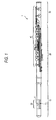
- Fig. 1 is a view showing the external view of the electronic flute 1 of the present embodiment.
- an enclosure of this electronic flute 1 includes an upper pipe section 10, a main pipe section 20, and a lower pipe section 30.
- Performance keys 40 serving as operation elements for receiving operation of fingers of the performer are provided on the main pipe section 20 and the lower pipe section 30.
- a lip plate 50 serving as an operation element for receiving operation of a lip is provided on the upper pipe section 10.
- the lip plate 50 is provided with a breath inlet hole 51 and an embouchure detection section 70.
- Fig. 2 is a cross-sectional view of the lip plate showing the configuration of the embouchure detection section 70.
- an indentation having an essentially-L-shaped cross sectional profile is formed in the base section in the area forward of the breath inlet hole 51 of the lip plate 50.
- An embouchure detection section 70 including a swinging portion 71, a formed rubber 72, and a membrane switch 73 is housed in the indentation.
- the membrane switch 73 is configured that an upper electrode sheet 73a having an electrode on a front surface thereof and a lower electrode sheet 73b having an electrode on a front surface thereof are arranged in such a way that a membrane space 73c and pressure-sensitive conductive rubber 73d are sandwiched between the front surfaces of the upper and the lower electrode sheets 73a and 73b.
- the back surface of the lower electrode sheet 73b is bonded to a longitudinal face of the indentation.
- the swinging portion 71 is a member having a tapered shape which becomes thinner from an upper face to a lower face. A rear end of the upper face is joined to upper ends of lateral faces of the indentation so as to become swayable in the vertical direction.
- the front edge of the upper face of the swinging portion 71 is slightly bluff upwardly, to thus form an essentially-straight protruding section 74.
- the essentially-rectangular-parallelepiped formed rubber 72 is affixed to the lower face of the swinging portion 71.
- This swinging portion 71 transmits the contact force exerted by the lower lip of the performer to the membrane switch 73 by swaying movement of the actuator.
- the reason why the protruding section 74 is provided along the front edge of the upper face of the swinging portion 71 is because the contact pressure of the lower lip is transmitted to the membrane switch 73 with higher accuracy.
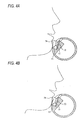
- Figs. 4A and 4B are drawings showing the principle on which the contact pressure of the lower lip of the performer to the swinging portion 71 is transmitted to the membrane switch 73.
- the pressure-sensitive conductive rubber 73d has the property of electrical resistance becoming smaller in the direction of compression as the rubber is compressed. Since a connection between the swinging portion 71 and the lip plate 50 is impelled upwardly with small force, the electrical resistance of the pressure-sensitive conductive rubber 73d becomes infinite when the swinging portion 71 is not depressed so as to contact to the pressure-sensitive conductive rubber 73d by the lower lip of the performer, as shown in Fig. 4A, whereby a voltage appearing in the point of contact between the upper electrode sheet 73a and the lower electrode sheet 73b becomes maximum.
- Fig. 5 is a view showing an electrical configuration of the electronic flute 1.
- the elements provided on the enclosure have already been described by reference to Fig. 1, and the like, the same reference numerals are assigned to those elements, and repeated descriptions thereof are omitted.
- the electronic flute 1 includes a breath sensor 91, a key sensor 92, an analog/digital (hereinafter called an "A/D") converter 93, a CPU 94, RAM 95, ROM 96, a sound source 97, and a sound system 98.
- A/D analog/digital
- the breath sensor 91 detects the pressure value of breath blown in the breath inlet hole 51 formed in the lip plate 50 of the upper pipe section 10, and supplies to the A/D converter 93 a signal showing the thus-detected pressure value.
- the key sensor 92 individually detects depression/nondepression of each of the performance keys 40 provided from the main pipe section 20 to the lower pipe section 30, and supplies the A/D converter 93 with a signal showing the depressed state of each of the keys.
- the A/D converter 93 subjects a signal supplied by the breath sensor 91 to A/D conversion, and supplies the CPU 94 with the thus-converted signal as breath pressure data.
- the A/D converter subjects the signal supplied from the key sensor 92 to A/D conversion, and supplies the thus-converted data to the CPU 94 as depressed key data.
- the A/D converter 93 subjects to A/D conversion a voltage value applied between the electrodes of the upper and lower electrode sheets 73a and 73b of the membrane switch 73, and supplies the resultant value to the CPU 94 as contact pressure data.
- the ROM 96 stores a fingering table 96a and a sound source control program 96b.
- Fig. 6 is a view showing the data structure of the fingering table 96a. As illustrated, this table has three fields; namely, the field of "fingering,” the field of "first octave,” and the field of "second octave.”
- Depression key data showing fingering are stored in the field of "fingering.”
- First octave pitch data are stored in the field of "first octave.”
- the first octave pitch data are data showing the pitch of musical sound output during playing at a standard embouchure.
- Second octave pitch data are stored in the field of "second octave.”
- the second octave pitch data are data indicating a pitch which is higher than the first octave pitch data by one octave.
- the sound source control program 96b is a program for imparting the CPU 94 with a characteristic feature of the present embodiment.
- the sound source 97 has waveform memory into which sound waveform data at each of the pitches of the flute are gathered.
- the sound source 97 Upon receipt, from the CPU 94, of the sound source control signal used for specifying the pitch of an output sound, the sound source 97 amplifies to a preset sound level a sound signal synthesized on the basis of the sound waveform data that are stored in the waveform memory of the sound source in association with the pitch; and supplies the sound system 98 with the amplified sound signal.
- the sound system 98 produces a sound corresponding to the sound signal.
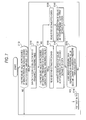
- Fig. 7 is a flowchart showing operation of the present embodiment.
- Illustrated processing is performed every time the breath pressure data are supplied to the CPU 94.
- the CPU 94 Upon receipt of a supply of breath pressure data from the A/D converter 93, the CPU 94 determines whether or not a pressure value indicated by the supplied breath pressure data has exceeded the preset breath pressure threshold value (S100).
- the CPU 94 specifies, from the fingering table 96a, the record stored in the field of "fingering" through use of the depression key data supplied from the A/D converter 93 (S110).
- the CPU 94 having specified the record in the fingering table 96a determines whether or not the pressure value represented by the contact pressure data supplied from the A/D converter 93 has exceeded the contact pressure threshold value that is another preset threshold value (S120).
- step 120 when the pressure value represented by the contact pressure data is determined not to have exceeded the contact pressure threshold value, the CPU 94 reads the first octave pitch data stored in the field of "first octave" belonging to the record specified in step S110 (S130).
- the CPU 94 supplies the sound source 97 with the sound source control signal that instructs generation of sound at a pitch represented by the one octave pitch data read in step 130 (S140). Thereby, sound at a pitch corresponding to standard embouchure is generated by the sound system 98.
- step 120 When in step 120 the pressure value represented by the contact pressure data is determined to have exceeded the contact pressure threshold value, the CPU 94 reads the second octave pitch data stored in the field of "second octave" belonging to the record specified in step 110 (S150).
- the CPU 94 supplies the sound source 97 with a sound source control signal which instructs generation of sound at a pitch represented by the second octave pitch data read in step 150 (S160).
- the pitch of the sound that has been generated by the sound system 98 thus far is switched to a pitch corresponding to octave-raised embouchure.
- the CPU 94 having supplied the sound source control signal in step 140 or 160 determines whether or not the pressure value represented by the breath pressure data that have been subsequently supplied from the A/D converter 93 has become smaller than the breath pressure threshold value (S170).
- the CPU 94 supplies the sound source 97 with the sound source control signal indicating a mute (S180). Generation of sound is stopped by the sound system 98, and processing subsequent to step 100 is iterated when the pressure value represented by the breath pressure data has again exceeded the breath pressure threshold value.
- the electronic flute 1 of the present embodiment having been described thus far has the embouchure detection section 70 for measuring the pressure at which the lower lip of the performer is brought into contact with the lip plate 50.
- the pressure value detected by the embouchure detection section 70 has exceeded the threshold value, the pitch of the sound output from the sound source 97 is changed higher by one octave.
- each of the records forming the fingering table 96a includes three fields; namely, the field of "fingering," the field of "first octave,” and the field of "second octave.”
- a record to which a reference is to be made is specified in the table 96a while the fingering represented by the depressed key data is taken as a search key.
- a determination is made as to whether pitch data are read from the field of "first octave” or the field of "second octave” according to a result of comparison between the pressure represented by the contact pressure data and the contact pressure threshold value.
- pitch data to be read are uniquely specified without making such a two-step determination, by making reference to the fingering table 96a while a combination of the result of comparison between the pressure value represented by the contact pressure data and the contact pressure threshold value with fingering represented by the depressed key data is taken as a search key.
- the hardware configuration of the electronic flute 1 of the present embodiment is the same as that of the first embodiment, except for the data structure of the fingering table 96a.
- Each of the records constituting the fingering table 96a of the present embodiment has two fields; namely, the field of "fingering" and the field of "pitch.” Pitch data indicating a pitch are stored in the field of pitch.
- Fig. 8 is a flowchart showing operation of the electronic flute of the present embodiment. In the drawing, processing pertaining to steps 110 to 160 in Fig. 7 is replaced with processing pertaining to steps 111 to 141.
- step 111 the CPU 94 specifies, in the fingering table 96a, fingering represented by the depressed key data supplied from the A/D converter 93 and the record corresponding to a result of comparison of the pressure value represented by the contact pressure data with the contact pressure threshold value.
- step 131 the pitch data stored in the field of "pitch" pertaining to the record specified in step 111 are read.
- the sound source 97 is supplied with a sound source control signal for instructing generation of sound at the pitch represented by the pitch data.
- the above embodiments are for realizing performance operability of a flute, which is a woodwind musical instrument, by an electronic musical instrument.
- the present invention may also be applied to another musical instrument which alters an octave by embouchure while fingering is fixed.
- the essentially-linear protruding section 74 is provided on the front edge of the upper surface of the swinging portion 71 serving as a contact member of the lip plate 50 to be brought into contact with the lower lip of the performer.
- the swinging portion 71 may also be configured in another shape.
- an outer shape of the swinging portion 71 to be brought into contact with the lower lip of the performer is shaped into a curved surface so as to continue to an outer shape of other portion of the lip plate 50 as shown in Fig. 9A.
- the rear end of the swinging portion 71 is joined, in a vertically-swayable manner, to the upper ends of the lateral faces of the L-shaped indentation of the lip plate 50.
- the swinging portion 71 and the lip plate 50 may also be joined together in another positional relationship.
- the swinging portion 71 may be pivotally jointed to an upper ends of the lateral faces of a U-shaped indentation of the lip plate 50 as shown in Figs. 9B and 9C.
- the swinging portion 71 may be arranged in the U-shaped indentation of the lip plate 50.
- the protruding section 74 provided on the swinging portion 71 may be shaped into a round portion as shown in Fig. 9B or a curves shape so as to continue to an outer shape of other portion of the lip plate 50 as shown in Fig. 9C.
- the electronic flute 1 incorporates the sound source 97 and the sound system 98.
- the electronic flute 1 is provided with an interface used for establishing connection with the external sound source 97.
- the external sound source 97 may also be controlled by outputting a sound source control signal via the interface.
- the sound source 97 of the present embodiment Upon receipt of a supply of a sound source control signal from the CPU 94, the sound source 97 of the present embodiment amplifies to a preset sound level the sound signal responsive to the sound source control signal, and supplies the sound system 98 with the amplified sound signal.
- the sound level of generated sound is constant regardless of strength of the breath of the performer.
- the CPU 94 having supplied the sound source 97 with the sound source control signal used for indicating an output of sound supplies the sound source 97 with a sound source control signal used for controlling a sound pressure level in accordance with the pressure value represented by the breath pressure data recently supplied to the CPU 94.
- the pitch of the sound output from the sound source 97 is changed higher than the pitch of the current sound by one octave.
- a pitch, a volume or a tone of the current sound may be slightly changed.
Landscapes
- Physics & Mathematics (AREA)
- Engineering & Computer Science (AREA)
- Acoustics & Sound (AREA)
- Multimedia (AREA)
- Electrophonic Musical Instruments (AREA)
Abstract
Description
- The present invention relates to an electronic wind instrument for electronically reproducing the blown sound of a natural wind instrument.
- As is well known, an electronic wind instrument has operation elements imitating their counterparts of a natural wind instrument, such as breath inlet holes and operation keys. When breath is blown into the instrument via the breath inlet hole, a pitch is determined in accordance with fingering that is a combination of depression of the performance key and the blowing of a breath. Blown sound whose level corresponds to the pressure of the breath blown in through a breath inlet hole is synthesized and produced at the thus-determined pitch.
- Attempts have hitherto been made to detect the style of rendition unique to the natural wind instrument called a "resonance mode change" and to realize an electronic music wind instrument capable of electronically reproducing the sound blown pursuant to the style of rendition.
- The "resonance mode change" means the style of rendition for a musical instrument which does not have performance keys used for switching an octave, as in the case of a flute. Under this style of rendition, movements of the lower lip called "embouchure" for blowing breath are subtly changed, to thus control an octave, or the like, of blown sound with fingering being fixed. Sometimes, the resonance mode change is also called an "overblow," an "octave switching," a "lip slur," and the like.
-
JP-A-7-199919 JP-A-7-199919 - However, as mentioned previously, the performer of a natural wind instrument performs a resonance mode change by subtly altering the manner of moving the lower lip rather than intentionally changing the direction of blowing of breath. Therefore, in the case of
JP-A-7-199919 - The present invention has been conceived against such a background and aims at providing an electronic wind instrument capable of reproducing, in a realistic manner, performance operability such as that achieved during the resonance mode change of a natural wind instrument.
- It is therefore an object of the present invention to provide an electronic musical instrument, comprising: a performance operation portion that is operated by fingers of a performer; a contact portion that is adapted to be brought into contact with a lower lip of the performer; a contact pressure detection portion that detects the contact pressure at which the lower lip is brought into contact with the contact portion, and generates a pressure value in accordance with the detected contact pressure; and a control portion that specifies sound of a pitch in accordance with an operation status of the performance operation portion and changes the pitch of the sound in accordance with the pressure value.
- Preferably, the contact pressure detection portion is a membrane switch. The membrane switch includes an upper electrode sheet having an electrode on a front surface thereof, a lower electrode sheet having an electrode on a front surface thereof, and a pressure-sensitive conductor sandwiched between the front surfaces of the upper and lower electrode sheets. A back surface of the lower electrode sheet is bonded to a lip member. One end of the contact portion is pivotally jointed to the lip member so that the upper electrode sheet can be depressed toward the lower electrode sheet in accordance with a movement of the contact portion.
- Preferably, a protruding section is provided on the contact portion.
- Preferably, the control portion determines whether or not the pressure value exceeds a predetermined threshold value. The control portion changes the pitch of the current sound to a pitch which is one octave higher than the pitch of the current sound when it is determined that the pressure value exceeds the threshold value.
- According to the present invention, there is also provided a computer-readable recording medium for causing an electronic musical instrument including a performance operation portion that is operated by fingers of a performer, a contact portion that is adapted to be brought into contact with a lower lip of the performer, a contact pressure detection portion that detects the contact pressure at which the lower lip is brought into contact with the contact portion and generates a pressure value in accordance with the detected contact pressure, to execute a pitch changing method, the method comprising:
- specifying sound of a pitch in accordance with an operation status of the performance operation portion; and
- changing the pitch of the sound in accordance with the pressure value.
- The present invention enables provision of an electronic musical instrument capable of realizing, in a realistic manner, performance operability such as that achieved when the resonance mode of a natural musical instrument is altered.
- The above objects and advantages of the present invention will become more apparent by describing in detail preferred exemplary embodiments thereof with reference to the accompanying drawings, wherein:
- Fig. 1 is a view showing the external view of an electronic flute;
- Fig. 2 is a view showing an embouchure detection section;
- Fig. 3 is a view showing a membrane switch;
- Figs. 4A and 4B are views showing the principle of transmission of a contact pressure of a lower lip to the membrane switch;
- Fig. 5 is a view showing the electrical configuration of the electronic flute;
- Fig. 6 is a view showing the data structure of a fingering table;
- Fig. 7 is a flowchart showing operation of the electronic flute according to a first embodiment;
- Fig. 8 is a flowchart showing operation of an electronic flute according to a second embodiment; and
- Figs. 9A to 9C are views showing modified embodiments of the embouchure detection section.
- A first embodiment of the present invention will be described.
- The feature of the present invention lies in that the sound source is caused to output musical sound of a pitch corresponding to standard embouchure in response to fingering detected by performance keys during the period of a pressure-at which the lower lip is brought into contact with a breath inlet hole of a flute-like electronic musical instrument (hereinafter called an "electronic flute")-remaining lower than a predetermined threshold value; and that, when the contact pressure has exceeded the threshold value, the sound source outputs musical sound of a pitch corresponding to an octave-raised embouchure.
- Fig. 1 is a view showing the external view of the electronic flute 1 of the present embodiment. As illustrated, an enclosure of this electronic flute 1 includes an
upper pipe section 10, amain pipe section 20, and alower pipe section 30.Performance keys 40 serving as operation elements for receiving operation of fingers of the performer are provided on themain pipe section 20 and thelower pipe section 30. Alip plate 50 serving as an operation element for receiving operation of a lip is provided on theupper pipe section 10. Moreover, thelip plate 50 is provided with abreath inlet hole 51 and anembouchure detection section 70. - Fig. 2 is a cross-sectional view of the lip plate showing the configuration of the
embouchure detection section 70. As illustrated, an indentation having an essentially-L-shaped cross sectional profile is formed in the base section in the area forward of thebreath inlet hole 51 of thelip plate 50. Anembouchure detection section 70 including a swingingportion 71, a formedrubber 72, and amembrane switch 73 is housed in the indentation. - As shown in Fig. 3, the
membrane switch 73 is configured that anupper electrode sheet 73a having an electrode on a front surface thereof and alower electrode sheet 73b having an electrode on a front surface thereof are arranged in such a way that amembrane space 73c and pressure-sensitiveconductive rubber 73d are sandwiched between the front surfaces of the upper and thelower electrode sheets lower electrode sheet 73b is bonded to a longitudinal face of the indentation. - In Fig. 2, the swinging
portion 71 is a member having a tapered shape which becomes thinner from an upper face to a lower face. A rear end of the upper face is joined to upper ends of lateral faces of the indentation so as to become swayable in the vertical direction. The front edge of the upper face of the swingingportion 71 is slightly bluff upwardly, to thus form an essentially-straight protrudingsection 74. The essentially-rectangular-parallelepiped formedrubber 72 is affixed to the lower face of the swingingportion 71. This swingingportion 71 transmits the contact force exerted by the lower lip of the performer to themembrane switch 73 by swaying movement of the actuator. The reason why theprotruding section 74 is provided along the front edge of the upper face of the swingingportion 71 is because the contact pressure of the lower lip is transmitted to themembrane switch 73 with higher accuracy. - Figs. 4A and 4B are drawings showing the principle on which the contact pressure of the lower lip of the performer to the swinging
portion 71 is transmitted to themembrane switch 73. As is well known, the pressure-sensitiveconductive rubber 73d has the property of electrical resistance becoming smaller in the direction of compression as the rubber is compressed. Since a connection between the swingingportion 71 and thelip plate 50 is impelled upwardly with small force, the electrical resistance of the pressure-sensitiveconductive rubber 73d becomes infinite when the swingingportion 71 is not depressed so as to contact to the pressure-sensitiveconductive rubber 73d by the lower lip of the performer, as shown in Fig. 4A, whereby a voltage appearing in the point of contact between theupper electrode sheet 73a and thelower electrode sheet 73b becomes maximum. As shown in Fig. 4B, when the lower lip of the performer depresses theprotuberance section 74 of the swingingportion 71 upon contacting the same, the electrical resistance of the pressure-sensitiveconductive rubber 73d becomes gradually lower, whereby the voltage across the point of contact is reduced. - Fig. 5 is a view showing an electrical configuration of the electronic flute 1. In the drawing, the elements provided on the enclosure have already been described by reference to Fig. 1, and the like, the same reference numerals are assigned to those elements, and repeated descriptions thereof are omitted. In addition to including the
membrane switch 73, the electronic flute 1 includes abreath sensor 91, akey sensor 92, an analog/digital (hereinafter called an "A/D")converter 93, aCPU 94,RAM 95,ROM 96, asound source 97, and asound system 98. - Features of the illustrated individual sections are generally described. First, the
breath sensor 91 detects the pressure value of breath blown in thebreath inlet hole 51 formed in thelip plate 50 of theupper pipe section 10, and supplies to the A/D converter 93 a signal showing the thus-detected pressure value. - The
key sensor 92 individually detects depression/nondepression of each of theperformance keys 40 provided from themain pipe section 20 to thelower pipe section 30, and supplies the A/D converter 93 with a signal showing the depressed state of each of the keys. - The A/
D converter 93 subjects a signal supplied by thebreath sensor 91 to A/D conversion, and supplies theCPU 94 with the thus-converted signal as breath pressure data. The A/D converter subjects the signal supplied from thekey sensor 92 to A/D conversion, and supplies the thus-converted data to theCPU 94 as depressed key data. Moreover, the A/D converter 93 subjects to A/D conversion a voltage value applied between the electrodes of the upper andlower electrode sheets membrane switch 73, and supplies the resultant value to theCPU 94 as contact pressure data. - The
ROM 96 stores a fingering table 96a and a soundsource control program 96b. - Fig. 6 is a view showing the data structure of the fingering table 96a. As illustrated, this table has three fields; namely, the field of "fingering," the field of "first octave," and the field of "second octave."
- Depression key data showing fingering are stored in the field of "fingering." First octave pitch data are stored in the field of "first octave." The first octave pitch data are data showing the pitch of musical sound output during playing at a standard embouchure. Second octave pitch data are stored in the field of "second octave." The second octave pitch data are data indicating a pitch which is higher than the first octave pitch data by one octave.
- The sound
source control program 96b is a program for imparting theCPU 94 with a characteristic feature of the present embodiment. - The
sound source 97 has waveform memory into which sound waveform data at each of the pitches of the flute are gathered. Upon receipt, from theCPU 94, of the sound source control signal used for specifying the pitch of an output sound, thesound source 97 amplifies to a preset sound level a sound signal synthesized on the basis of the sound waveform data that are stored in the waveform memory of the sound source in association with the pitch; and supplies thesound system 98 with the amplified sound signal. Thesound system 98 produces a sound corresponding to the sound signal. - Fig. 7 is a flowchart showing operation of the present embodiment.
- Illustrated processing is performed every time the breath pressure data are supplied to the
CPU 94. - Upon receipt of a supply of breath pressure data from the A/
D converter 93, theCPU 94 determines whether or not a pressure value indicated by the supplied breath pressure data has exceeded the preset breath pressure threshold value (S100). - When the pressure value represented by the breath pressure data are determined to have exceeded the breath pressure threshold value, the
CPU 94 specifies, from the fingering table 96a, the record stored in the field of "fingering" through use of the depression key data supplied from the A/D converter 93 (S110). - The
CPU 94 having specified the record in the fingering table 96a determines whether or not the pressure value represented by the contact pressure data supplied from the A/D converter 93 has exceeded the contact pressure threshold value that is another preset threshold value (S120). - In
step 120, when the pressure value represented by the contact pressure data is determined not to have exceeded the contact pressure threshold value, theCPU 94 reads the first octave pitch data stored in the field of "first octave" belonging to the record specified in step S110 (S130). - Subsequently, the
CPU 94 supplies thesound source 97 with the sound source control signal that instructs generation of sound at a pitch represented by the one octave pitch data read in step 130 (S140). Thereby, sound at a pitch corresponding to standard embouchure is generated by thesound system 98. - When in
step 120 the pressure value represented by the contact pressure data is determined to have exceeded the contact pressure threshold value, theCPU 94 reads the second octave pitch data stored in the field of "second octave" belonging to the record specified in step 110 (S150). - Next, the
CPU 94 supplies thesound source 97 with a sound source control signal which instructs generation of sound at a pitch represented by the second octave pitch data read in step 150 (S160). Thus, the pitch of the sound that has been generated by thesound system 98 thus far is switched to a pitch corresponding to octave-raised embouchure. - The
CPU 94 having supplied the sound source control signal instep D converter 93 has become smaller than the breath pressure threshold value (S170). - When the pressure value represented by the breath pressure data is determined to have become smaller than the breath pressure threshold value, the
CPU 94 supplies thesound source 97 with the sound source control signal indicating a mute (S180). Generation of sound is stopped by thesound system 98, and processing subsequent to step 100 is iterated when the pressure value represented by the breath pressure data has again exceeded the breath pressure threshold value. - The electronic flute 1 of the present embodiment having been described thus far has the
embouchure detection section 70 for measuring the pressure at which the lower lip of the performer is brought into contact with thelip plate 50. When the pressure value detected by theembouchure detection section 70 has exceeded the threshold value, the pitch of the sound output from thesound source 97 is changed higher by one octave. Thus, as a result of the contact pressure on thelip plate 50 being synchronized with the change in the octave of the sound output from thesound source 97, performance operability closer to that of the natural wind instrument can be implemented. - A second embodiment of the present invention will now be described.
- In the first embodiment, each of the records forming the fingering table 96a includes three fields; namely, the field of "fingering," the field of "first octave," and the field of "second octave." A record to which a reference is to be made is specified in the table 96a while the fingering represented by the depressed key data is taken as a search key. Subsequently, a determination is made as to whether pitch data are read from the field of "first octave" or the field of "second octave" according to a result of comparison between the pressure represented by the contact pressure data and the contact pressure threshold value. In contrast, in the present embodiment, pitch data to be read are uniquely specified without making such a two-step determination, by making reference to the fingering table 96a while a combination of the result of comparison between the pressure value represented by the contact pressure data and the contact pressure threshold value with fingering represented by the depressed key data is taken as a search key.
- The hardware configuration of the electronic flute 1 of the present embodiment is the same as that of the first embodiment, except for the data structure of the fingering table 96a. Each of the records constituting the fingering table 96a of the present embodiment has two fields; namely, the field of "fingering" and the field of "pitch." Pitch data indicating a pitch are stored in the field of pitch. Meanwhile, data showing a combination of fingering with a result of comparison between the contact pressure of the lip and the contact pressure threshold value (whether the contact pressure exceeds or is smaller than the threshold value) are stored in the field of "fingering." Therefore, even in the case of single fingering, the data representing the combination of the contact pressure threshold value with the value showing that the pressure value represented by the contact pressure data has exceeded the contact pressure threshold value are stored in one record, and the data showing the combination of the contact pressure threshold value with the value showing that the pressure value is not greater than the contact pressure threshold value are stored in another record.
- Fig. 8 is a flowchart showing operation of the electronic flute of the present embodiment. In the drawing, processing pertaining to
steps 110 to 160 in Fig. 7 is replaced with processing pertaining to steps 111 to 141. - In step 111, the
CPU 94 specifies, in the fingering table 96a, fingering represented by the depressed key data supplied from the A/D converter 93 and the record corresponding to a result of comparison of the pressure value represented by the contact pressure data with the contact pressure threshold value. - In
subsequent step 131, the pitch data stored in the field of "pitch" pertaining to the record specified in step 111 are read. Instep 141, thesound source 97 is supplied with a sound source control signal for instructing generation of sound at the pitch represented by the pitch data. - Even in the above-described embodiment, performance operability similar to that of the natural wind instrument can be embodied, and the pitch of sound output from the
sound source 97 can be specified by a simpler algorithm. - The above embodiments can be altered in various manners.
- The above embodiments are for realizing performance operability of a flute, which is a woodwind musical instrument, by an electronic musical instrument. However, the present invention may also be applied to another musical instrument which alters an octave by embouchure while fingering is fixed.
- In the present embodiment, the essentially-
linear protruding section 74 is provided on the front edge of the upper surface of the swingingportion 71 serving as a contact member of thelip plate 50 to be brought into contact with the lower lip of the performer. However, the swingingportion 71 may also be configured in another shape. For example, an outer shape of the swingingportion 71 to be brought into contact with the lower lip of the performer is shaped into a curved surface so as to continue to an outer shape of other portion of thelip plate 50 as shown in Fig. 9A. Moreover, the rear end of the swingingportion 71 is joined, in a vertically-swayable manner, to the upper ends of the lateral faces of the L-shaped indentation of thelip plate 50. However, the swingingportion 71 and thelip plate 50 may also be joined together in another positional relationship. For example, the swingingportion 71 may be pivotally jointed to an upper ends of the lateral faces of a U-shaped indentation of thelip plate 50 as shown in Figs. 9B and 9C. Especially, the swingingportion 71 may be arranged in the U-shaped indentation of thelip plate 50. Further, the protrudingsection 74 provided on the swingingportion 71 may be shaped into a round portion as shown in Fig. 9B or a curves shape so as to continue to an outer shape of other portion of thelip plate 50 as shown in Fig. 9C. In short, no limitations are imposed on the positional relationship between the swingingportion 71 and themembrane switch 73 or the technique of joining them together, so long as theupper electrode sheet 73a of the membrane switch is joined to one end of the swingingportion 71 at a position where the upper electrode sheet can be depressed toward thelower electrode sheet 73b. - In the present embodiment, the electronic flute 1 incorporates the
sound source 97 and thesound system 98. However, the electronic flute 1 is provided with an interface used for establishing connection with theexternal sound source 97. Theexternal sound source 97 may also be controlled by outputting a sound source control signal via the interface. Upon receipt of a supply of a sound source control signal from theCPU 94, thesound source 97 of the present embodiment amplifies to a preset sound level the sound signal responsive to the sound source control signal, and supplies thesound system 98 with the amplified sound signal. Hence, the sound level of generated sound is constant regardless of strength of the breath of the performer. In contrast, there may also be adopted a configuration of synchronizing the pressure of the breath blown in from thebreath inlet hole 51 with the sound level as well as with output or non-output of sound. In this modification, theCPU 94 having supplied thesound source 97 with the sound source control signal used for indicating an output of sound supplies thesound source 97 with a sound source control signal used for controlling a sound pressure level in accordance with the pressure value represented by the breath pressure data recently supplied to theCPU 94. - In the embodiments, when the pressure value detected by the
embouchure detection section 70 exceeds the threshold value, the pitch of the sound output from thesound source 97 is changed higher than the pitch of the current sound by one octave. However, as alternative to the change of the octave, when the pressure value detected by theembouchure detection section 70 exceeds the threshold value, a pitch, a volume or a tone of the current sound may be slightly changed. - Although the invention has been illustrated and described for the particular preferred embodiments, it is apparent to a person skilled in the art that various changes and modifications can be made on the basis of the teachings of the invention. It is apparent that such changes and modifications are within the spirit, scope, and intention of the invention as defined by the appended claims.
Claims (5)
- An electronic musical instrument, comprising:a performance operation portion that is operated by fingers of a performer;a contact portion that is adapted to be brought into contact with a lower lip of the performer;a contact pressure detection portion that detects the contact pressure at which the lower lip is brought into contact with the contact portion, and
generates a pressure value in accordance with the detected contact pressure; anda control portion that specifies sound of a pitch in accordance with an operation status of the performance operation portion and changes the pitch of the sound in accordance with the pressure value. - The electronic musical instrument according to claim 1, wherein the contact pressure detection portion is a membrane switch;
wherein the membrane switch includes:an upper electrode sheet having an electrode on a front surface thereof;a lower electrode sheet having an electrode on a front surface thereof; anda pressure-sensitive conductor sandwiched between the front surfaces of the upper and lower electrode sheets;wherein a back surface of the lower electrode sheet is bonded to a lip member; and
wherein one end of the contact portion is pivotally jointed to the lip member so that the upper electrode sheet can be depressed toward the lower electrode sheet in accordance with a movement of the contact portion. - The electronic musical instrument according to claim 1or 2, wherein a protruding section is provided on the contact portion.
- The electronic musical instrument according to one of claims 1 to 3, wherein the control portion determines whether or not the pressure value exceeds a predetermined threshold value; and
wherein the control portion changes the pitch of the current sound to a pitch which is one octave higher than the pitch of the current sound when it is determined that the pressure value exceeds the threshold value. - A computer-readable recording medium for causing an electronic musical instrument including a performance operation portion that is operated by fingers of a performer, a contact portion that is adapted to be brought into contact with a lower lip of the performer, a contact pressure detection portion that detects the contact pressure at which the lower lip is brought into contact with the contact portion and generates a pressure value in accordance with the detected contact pressure, to execute a pitch changing method, the method comprising:specifying sound of a pitch in accordance with an operation status of the performance operation portion; andchanging the pitch of the sound in accordance with the pressure value.
Applications Claiming Priority (1)
| Application Number | Priority Date | Filing Date | Title |
|---|---|---|---|
| JP2005367996A JP4462180B2 (en) | 2005-12-21 | 2005-12-21 | Electronic wind instrument and program thereof |
Publications (1)
| Publication Number | Publication Date |
|---|---|
| EP1801779A1 true EP1801779A1 (en) | 2007-06-27 |
Family
ID=37692540
Family Applications (1)
| Application Number | Title | Priority Date | Filing Date |
|---|---|---|---|
| EP06026438A Withdrawn EP1801779A1 (en) | 2005-12-21 | 2006-12-20 | Electronic musical instrument and computer-readable recording medium |
Country Status (4)
| Country | Link |
|---|---|
| US (1) | US7772482B2 (en) |
| EP (1) | EP1801779A1 (en) |
| JP (1) | JP4462180B2 (en) |
| CN (1) | CN1987996B (en) |
Cited By (3)
| Publication number | Priority date | Publication date | Assignee | Title |
|---|---|---|---|---|
| EP2006834A1 (en) * | 2007-06-20 | 2008-12-24 | Yamaha Corporation | Electronic wind instrument |
| CN101960940B (en) * | 2008-02-26 | 2012-07-25 | 京瓷株式会社 | Vacuum suction nozzle |
| US8895826B2 (en) | 2011-12-26 | 2014-11-25 | Chris Nowselski | Automatic embouchure |
Families Citing this family (12)
| Publication number | Priority date | Publication date | Assignee | Title |
|---|---|---|---|---|
| JP4218663B2 (en) * | 2005-06-21 | 2009-02-04 | ヤマハ株式会社 | Wind instrument key detection structure |
| US7902450B2 (en) * | 2006-01-17 | 2011-03-08 | Lippold Haken | Method and system for providing pressure-controlled transitions |
| US7723605B2 (en) * | 2006-03-28 | 2010-05-25 | Bruce Gremo | Flute controller driven dynamic synthesis system |
| JP4957399B2 (en) * | 2007-06-20 | 2012-06-20 | ヤマハ株式会社 | Mandible motion detection device for electronic wind instruments |
| JP5104055B2 (en) * | 2007-06-20 | 2012-12-19 | ヤマハ株式会社 | Electronic flute mandibular movement detection device |
| JP4798218B2 (en) * | 2008-12-26 | 2011-10-19 | ブラザー工業株式会社 | Telephone device |
| US8581087B2 (en) * | 2010-09-28 | 2013-11-12 | Yamaha Corporation | Tone generating style notification control for wind instrument having mouthpiece section |
| JP6435644B2 (en) * | 2014-05-29 | 2018-12-12 | カシオ計算機株式会社 | Electronic musical instrument, pronunciation control method and program |
| US10360884B2 (en) * | 2017-03-15 | 2019-07-23 | Casio Computer Co., Ltd. | Electronic wind instrument, method of controlling electronic wind instrument, and storage medium storing program for electronic wind instrument |
| JP6941303B2 (en) * | 2019-05-24 | 2021-09-29 | カシオ計算機株式会社 | Electronic wind instruments and musical tone generators, musical tone generators, programs |
| CN111260995B (en) * | 2020-03-05 | 2021-08-10 | 电子科技大学 | Guzheng training ware and zither training system |
| CN113496690A (en) * | 2020-03-22 | 2021-10-12 | 张磊 | Electronic wind instrument |
Citations (5)
| Publication number | Priority date | Publication date | Assignee | Title |
|---|---|---|---|---|
| US2138500A (en) * | 1936-10-28 | 1938-11-29 | Miessner Inventions Inc | Apparatus for the production of music |
| US3767833A (en) * | 1971-10-05 | 1973-10-23 | Computone Inc | Electronic musical instrument |
| GB2221078A (en) * | 1988-06-17 | 1990-01-24 | Casio Computer Co Ltd | "Electronic musical instrument with musical tone parameter switching function" |
| US5245130A (en) * | 1991-02-15 | 1993-09-14 | Yamaha Corporation | Polyphonic breath controlled electronic musical instrument |
| US5543580A (en) * | 1990-10-30 | 1996-08-06 | Yamaha Corporation | Tone synthesizer |
Family Cites Families (9)
| Publication number | Priority date | Publication date | Assignee | Title |
|---|---|---|---|---|
| US4314228A (en) * | 1980-04-16 | 1982-02-02 | Eventoff Franklin Neal | Pressure transducer |
| JPH0697396B2 (en) | 1987-06-22 | 1994-11-30 | ヤマハ株式会社 | Mouse piece for electronic wind instrument |
| JPH0772853A (en) | 1993-06-29 | 1995-03-17 | Yamaha Corp | Electronic wind instrument |
| JP3346008B2 (en) | 1993-12-28 | 2002-11-18 | カシオ計算機株式会社 | Electronic wind instrument |
| JPH08305362A (en) | 1995-05-09 | 1996-11-22 | Yamaha Corp | Electronic wind instrument |
| JPH1055178A (en) | 1996-08-09 | 1998-02-24 | Casio Comput Co Ltd | Electronic wind instrument |
| JPH10149737A (en) | 1996-11-19 | 1998-06-02 | Fujikura Ltd | Membrane switch |
| JP3307287B2 (en) * | 1997-07-29 | 2002-07-24 | ヤマハ株式会社 | Electronic wind instrument |
| JP2003141962A (en) | 2001-11-05 | 2003-05-16 | Alps Electric Co Ltd | Keyboard unit and its manufacturing method |
-
2005
- 2005-12-21 JP JP2005367996A patent/JP4462180B2/en not_active Expired - Fee Related
-
2006
- 2006-12-19 US US11/612,891 patent/US7772482B2/en not_active Expired - Fee Related
- 2006-12-20 EP EP06026438A patent/EP1801779A1/en not_active Withdrawn
- 2006-12-21 CN CN2006101702257A patent/CN1987996B/en not_active Expired - Fee Related
Patent Citations (5)
| Publication number | Priority date | Publication date | Assignee | Title |
|---|---|---|---|---|
| US2138500A (en) * | 1936-10-28 | 1938-11-29 | Miessner Inventions Inc | Apparatus for the production of music |
| US3767833A (en) * | 1971-10-05 | 1973-10-23 | Computone Inc | Electronic musical instrument |
| GB2221078A (en) * | 1988-06-17 | 1990-01-24 | Casio Computer Co Ltd | "Electronic musical instrument with musical tone parameter switching function" |
| US5543580A (en) * | 1990-10-30 | 1996-08-06 | Yamaha Corporation | Tone synthesizer |
| US5245130A (en) * | 1991-02-15 | 1993-09-14 | Yamaha Corporation | Polyphonic breath controlled electronic musical instrument |
Non-Patent Citations (1)
| Title |
|---|
| YAMAHA: "WX5 wind midi controller owner's manual", 3 March 1998, YAMAHA, JAPAN, XP002419055 * |
Cited By (4)
| Publication number | Priority date | Publication date | Assignee | Title |
|---|---|---|---|---|
| EP2006834A1 (en) * | 2007-06-20 | 2008-12-24 | Yamaha Corporation | Electronic wind instrument |
| US7781667B2 (en) | 2007-06-20 | 2010-08-24 | Yamaha Corporation | Electronic wind instrument |
| CN101960940B (en) * | 2008-02-26 | 2012-07-25 | 京瓷株式会社 | Vacuum suction nozzle |
| US8895826B2 (en) | 2011-12-26 | 2014-11-25 | Chris Nowselski | Automatic embouchure |
Also Published As
| Publication number | Publication date |
|---|---|
| JP4462180B2 (en) | 2010-05-12 |
| JP2007171477A (en) | 2007-07-05 |
| CN1987996A (en) | 2007-06-27 |
| US20070137468A1 (en) | 2007-06-21 |
| US7772482B2 (en) | 2010-08-10 |
| CN1987996B (en) | 2011-06-08 |
Similar Documents
| Publication | Publication Date | Title |
|---|---|---|
| US7772482B2 (en) | Electronic musical instrument and computer-readable recording medium | |
| JP3799592B2 (en) | Electronic keyboard instrument | |
| CN100527218C (en) | Key actuating system | |
| US8324488B2 (en) | Pedal apparatus of an electronic musical instrument | |
| JP2005521922A (en) | Winding electronic piano | |
| JP4183625B2 (en) | Electronic percussion instrument | |
| JP6485082B2 (en) | Keyboard instrument | |
| US9697816B2 (en) | Keyboard unit | |
| US6849796B2 (en) | Operation detection switch, musical instrument and parameter determination program | |
| JP5315883B2 (en) | Electronic musical instrument and musical sound generation program | |
| JP4419966B2 (en) | Electronic wind instrument and program thereof | |
| JP5707693B2 (en) | Electronic keyboard instrument | |
| JP3489141B2 (en) | Electronic musical instrument and its keyboard device | |
| JP2930160B2 (en) | Keyboard device and control method | |
| JP4219284B2 (en) | Keyboard device | |
| JPH07104754A (en) | Electronic musical instrument built-in piano | |
| JP3331715B2 (en) | Keyboard device | |
| JP3824040B2 (en) | Keyboard device with touch control function | |
| JP2579748Y2 (en) | Keyboard device | |
| JP3664086B2 (en) | Electronic instrument touch response device | |
| JP2910210B2 (en) | Touch-sensitive device for electronic musical instruments | |
| JP2026058601A (en) | Electronic keyboard instrument | |
| JP2734178B2 (en) | Electronic musical instrument | |
| JP3694988B2 (en) | Electronic musical instruments | |
| JPH09274486A (en) | Harmonica type keyboard instrument |
Legal Events
| Date | Code | Title | Description |
|---|---|---|---|
| PUAI | Public reference made under article 153(3) epc to a published international application that has entered the european phase |
Free format text: ORIGINAL CODE: 0009012 |
|
| AK | Designated contracting states |
Kind code of ref document: A1 Designated state(s): AT BE BG CH CY CZ DE DK EE ES FI FR GB GR HU IE IS IT LI LT LU LV MC NL PL PT RO SE SI SK TR |
|
| AX | Request for extension of the european patent |
Extension state: AL BA HR MK YU |
|
| RAP1 | Party data changed (applicant data changed or rights of an application transferred) |
Owner name: YAMAHA CORPORATION |
|
| 17P | Request for examination filed |
Effective date: 20070801 |
|
| AKX | Designation fees paid |
Designated state(s): AT BE BG CH CY CZ DE DK EE ES FI FR GB GR HU IE IS IT LI LT LU LV MC NL PL PT RO SE SI SK TR |
|
| GRAP | Despatch of communication of intention to grant a patent |
Free format text: ORIGINAL CODE: EPIDOSNIGR1 |
|
| RIC1 | Information provided on ipc code assigned before grant |
Ipc: G10H 1/20 20060101ALI20160621BHEP Ipc: G10H 1/055 20060101AFI20160621BHEP Ipc: G10H 1/34 20060101ALI20160621BHEP |
|
| INTG | Intention to grant announced |
Effective date: 20160725 |
|
| STAA | Information on the status of an ep patent application or granted ep patent |
Free format text: STATUS: THE APPLICATION IS DEEMED TO BE WITHDRAWN |
|
| 18D | Application deemed to be withdrawn |
Effective date: 20161206 |