EP1801575A1 - An eddy current inspection device - Google Patents
An eddy current inspection device Download PDFInfo
- Publication number
- EP1801575A1 EP1801575A1 EP06126785A EP06126785A EP1801575A1 EP 1801575 A1 EP1801575 A1 EP 1801575A1 EP 06126785 A EP06126785 A EP 06126785A EP 06126785 A EP06126785 A EP 06126785A EP 1801575 A1 EP1801575 A1 EP 1801575A1
- Authority
- EP
- European Patent Office
- Prior art keywords
- eddy current
- computer
- image
- component
- frequency components
- Prior art date
- Legal status (The legal status is an assumption and is not a legal conclusion. Google has not performed a legal analysis and makes no representation as to the accuracy of the status listed.)
- Withdrawn
Links
- 238000007689 inspection Methods 0.000 title claims abstract description 30
- 239000000523 sample Substances 0.000 claims abstract description 33
- 238000012360 testing method Methods 0.000 claims abstract description 7
- 238000000034 method Methods 0.000 claims description 40
- 230000007547 defect Effects 0.000 claims description 9
- 238000012545 processing Methods 0.000 claims description 4
- 238000001514 detection method Methods 0.000 description 6
- 229910045601 alloy Inorganic materials 0.000 description 5
- 239000000956 alloy Substances 0.000 description 5
- 239000000463 material Substances 0.000 description 5
- 230000008569 process Effects 0.000 description 4
- 238000011109 contamination Methods 0.000 description 2
- 238000010586 diagram Methods 0.000 description 2
- 230000002159 abnormal effect Effects 0.000 description 1
- 238000013459 approach Methods 0.000 description 1
- 230000000694 effects Effects 0.000 description 1
- 230000005672 electromagnetic field Effects 0.000 description 1
- 230000006870 function Effects 0.000 description 1
- 238000010438 heat treatment Methods 0.000 description 1
- 238000003384 imaging method Methods 0.000 description 1
- 230000003993 interaction Effects 0.000 description 1
- 238000013178 mathematical model Methods 0.000 description 1
- 238000012986 modification Methods 0.000 description 1
- 230000004048 modification Effects 0.000 description 1
- 230000003287 optical effect Effects 0.000 description 1
- 230000004044 response Effects 0.000 description 1
- 238000005204 segregation Methods 0.000 description 1
- 239000007787 solid Substances 0.000 description 1
Images


Classifications
-
- G—PHYSICS
- G01—MEASURING; TESTING
- G01N—INVESTIGATING OR ANALYSING MATERIALS BY DETERMINING THEIR CHEMICAL OR PHYSICAL PROPERTIES
- G01N27/00—Investigating or analysing materials by the use of electric, electrochemical, or magnetic means
- G01N27/72—Investigating or analysing materials by the use of electric, electrochemical, or magnetic means by investigating magnetic variables
- G01N27/82—Investigating or analysing materials by the use of electric, electrochemical, or magnetic means by investigating magnetic variables for investigating the presence of flaws
- G01N27/90—Investigating or analysing materials by the use of electric, electrochemical, or magnetic means by investigating magnetic variables for investigating the presence of flaws using eddy currents
- G01N27/9046—Investigating or analysing materials by the use of electric, electrochemical, or magnetic means by investigating magnetic variables for investigating the presence of flaws using eddy currents by analysing electrical signals
Definitions
- This invention relates generally to the testing of components, and more particularly to methods and apparatus for testing components having non-uniform surfaces.
- Eddy current (EC) inspection devices are used to detect abnormal indications in a component under test such as, but not limited to, a gas turbine engine component. At least one known EC inspection device is used to detect cracks, pings, dings, raised material, and/or other surface imperfections on a surface of the component, and/or to evaluate material properties of the component including the conductivity, density, and/or degrees of heat treatment of the component.
- known EC devices measure the interaction between an electromagnetic field generated by the EC device and the component being tested.
- known EC devices include a probe coil that generates a magnetic field. When the coil is positioned adjacent to a conductive component, an eddy current is generated on the surface of the component. A flaw on and/or near the surface of the component generates a disruption in the eddy current field which produces a secondary field that is received by the eddy current probe coil or by a sensor coil in the eddy current probe which converts the altered secondary magnetic field to an electrical signal that may be recorded on a strip chart recorder for example.
- the eddy current inspection device may be affected by a variety of conditions that the probe may encounter while inspecting the component. For example, the eddy current inspection system may generate a relatively uniform signal when the EC inspection system detects a surface crack near a uniform surface region of the component.
- the EC inspection system may generate a spurious signal when a crack or flaw is detected near the edge of a component that includes relatively complex geometric features. Therefore, it is relatively difficult for an operator to distinguish geometric edge signals generated by the EC device when the EC device is passed over a crack and/or seam at the edge of a component. More specifically, it is often difficult for an operator to distinguish the signals generated from a real crack and/or seam from the spurious signals that may be generated near the edge of a component that has a relatively complex geometry.
- At least one known EC device generates real-time images from identical, repeated geometries in a component, to facilitate improving images that include spurious signals. More specifically, a plurality of images are generated along the surface of the component, wherein each image represents only a portion of the component. After several of these images are collected, a subtraction process is utilized to extract the images from adjacent features. While this method facilitates reducing the dominant edge signals that are common to adjacent features, the method does not eliminate spurious edge signals that are caused by the geometry variations within the component. Accordingly, if only one component feature is to be inspected, the method is less effective because there are no repeated images to subtract.
- a method of inspecting a component includes generating a raw image of a component under test utilizing an eddy current inspection system, decomposing the raw image into a plurality of images wherein each image includes a different frequency component, and reconstructing at least one final image of the component that includes frequency components that are relevant to an eddy current flaw signal.
- an eddy current inspection system in another aspect, includes an eddy current probe, and a computer coupled to the eddy current probe.
- the computer is configured to generate a raw image of a feature under test, decompose the raw image into a plurality of images wherein each image includes a different frequency component, and reconstruct at least one final image of the component that includes frequency components that are relevant to an eddy current flaw signal.
- FIG. 1 is a schematic illustration of a gas turbine engine 10 including a fan assembly 12 and a core engine 13 including a high pressure compressor 14, and a combustor 16.
- Engine 10 also includes a high pressure turbine 18, a low pressure turbine 20, and a booster 22.
- Fan assembly 12 includes an array of fan blades 24 extending radially outward from a rotor disc 26.
- Engine 10 has an intake side 27 and an exhaust side 29.
- the gas turbine engine is a CF6-50 available from General Electric Company, Cincinnati, Ohio.
- Fan assembly 12 and turbine 20 are coupled by a first rotor shaft 31, and compressor 14 and turbine 18 are coupled by a second rotor shaft 33.
- Airflow (not shown in Figure 1) from combustor 16 drives turbines 18 and 20, and turbine 20 drives fan assembly 12 by way of shaft 31.
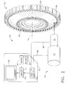
- Figure 2 is a schematic diagram of an exemplary eddy current flaw detection system 50 that can be used to inspect a component 52 such as, but not limited to, a gas turbine engine disk 54 which may be used with gas turbine engine 10.
- disk 54 includes a plurality of dovetail posts 56 and a plurality of dovetail slots 58 defined between posts 56.
- component 52 may be of any operable shape, size, and configuration. Examples of such components may include, but are not limited to, components of gas turbine engines such as seals, flanges, turbine blades, turbine vanes, and/or flanges.
- the component may be fabricated of any operable base material such as, but not limited to, nickel-base alloys, cobalt-base alloys, titanium-base alloys, iron-base alloys, and/or aluminum-base alloys. More specifically, although the methods and apparatus herein are described with respect to aircraft engine components, it should be appreciated that the methods and apparatus can be applied to a wide variety of components used within a steam turbine, a nuclear power plant, an automotive engine, or to inspect any mechanical components.
- detection system 50 includes a probe assembly 60 and a data acquisition/control system 62.
- Probe assembly 60 includes an eddy current coil/probe 70 and a probe manipulator 72 that is coupled to probe 70.
- Eddy current probe 70 and probe manipulator 72 are each electrically coupled to data acquisition/control system 62 such that control/data information can be transmitted to/from eddy current probe 70/probe manipulator 72 and data acquisition/control system 62.
- system 50 also includes a turntable (not shown) configured to rotate component 52 around a central axis 74 during the inspection procedure.
- Data acquisition/control system 62 includes a computer interface 76, a computer 78, such as a personal computer with a memory 80, and a monitor 82.
- Computer 78 executes instructions stored in firmware (not shown).
- Computer 78 is programmed to perform functions described herein, and as used herein, the term computer is not limited to just those integrated circuits referred to in the art as computers, but broadly refers to computers, processors, microcontrollers, microcomputers, programmable logic controllers, application specific integrated circuits, and other programmable circuits, and these terms are used interchangeably herein.
- Memory 80 is intended to represent one or more volatile and/or nonvolatile storage facilities that shall be familiar to those skilled in the art. Examples of such storage facilities often used with computer 78 include, but are not limited to, solid state memory (e.g., random access memory (RAM), read-only memory (ROM), and flash memory), magnetic storage devices (e.g., floppy disks and hard disks), and/or optical storage devices (e.g., CD-ROM, CD-RW, and DVD). Memory 80 may be internal to or external from computer 78.
- Data acquisition/control system 62 also includes a recording device 84 such as, but not limited to, a strip chart recorder, a C-scan, and an electronic recorder that is electrically coupled to either computer 78 and/or eddy current probe 70.
- a recording device 84 such as, but not limited to, a strip chart recorder, a C-scan, and an electronic recorder that is electrically coupled to either computer 78 and/or eddy current probe 70.
- component 52 such as disk 54
- Eddy current probe 70 is positioned within dovetail slots 58 to facilitate enabling substantially all of the interior of dovetail slots 58 to be scanned during inspection.
- probe manipulator 72 is a six-axis manipulator.
- Eddy current probe 70 generates electrical signals in response to the eddy currents induced within the surface of dovetail slots 58 during scanning of dovetail slots 58 by probe 70. Electrical signals generated by probe 70 are received by data acquisition/control system 62 over a data communications link 86 and are either stored in memory 80 or recorder 84.
- Computer 78 is also interconnected to probe manipulator 72 by a communications link 88 to facilitate controlling the scanning of disk 54.
- a keyboard (not shown) is electrically coupled to computer 78 to facilitate operator control of the inspection of disk 54.
- a printer (not shown) may be provided to generate hard copies of the images generated by computer 78.
- Figure 3 is a flow chart illustrating an exemplary method 100 for inspecting a component having a surface that includes a local minima and a local maxima.
- Method 100 includes generating 102 a raw image, decomposing 104 the raw image into a plurality of images wherein each image includes a different frequency component, and reconstructing 106 at least one final image that includes frequency components that are relevant to an EC flaw signal.
- eddy current flaw detection system 50 is utilized to inspect a component 52 such as, but not limited to, a gas turbine engine disk 54 and then to generate a raw image.
- the raw image is then processed in a two-step procedure to facilitate identifying a crack or other flaw which may occur in component 54.
- the raw image is decomposed 104 into a plurality of images wherein each image includes with different frequency components.
- the raw image is processed utilizing a two-level Wavelet Image Processing technique.
- the raw image is decomposed into a plurality of images.
- the raw image is decomposed into five separate images.
- the raw image may be decomposed into a desired quantity of images to facilitate identifying cracks or other defects, without affecting the scope of the invention described herein.
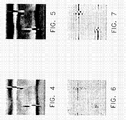
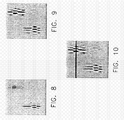
- the raw image (shown in Figure 4) is filtered using a low-pass convolution filter to generate a first image (shown in Figure 5), the raw image is filtered using a high band pass filter in a horizontal direction to generate a second image (shown in Figure 6), the raw image is filtered using a medium band pass filter in a horizontal direction to generate a third image (shown in Figure 7), the raw image is filtered using a high band pass filter in a vertical direction to generate a fourth image (shown in Figure 8), and the raw image is filtered using a medium band pass filter in a vertical direction to generate a fifth image (shown in Figure 9).
- the component flaws are clearly visible while the edge signals are completely removed.
- the image of Figure 8 was processed utilizing a high band pass filter which facilitated removing the edge signals which generally have a lower frequency than the frequency of the signals generated by any defects within the component.
- the image of Figure 6 which was generated by processing the raw image utilizing a high band pass filter in a horizontal direction contains edge signals from which the flaw signal can not be easily segregated.
- Method 100 further includes, reconstructing 106 a final image that includes frequency components that are relevant to eddy current flaw signals.
- known eddy current flaw signals generally have a frequency and/or amplitude that is different than the amplitude and/or frequency of a signal that is generated due to noise or edge signals during the inspection process.
- These characteristics are stored as apriori knowledge within computer 78, for example.
- computer 78 includes information of the frequency and/or amplitude of a wide variety of known flaws or defects such that during the inspection procedure, computer 78 is enabled to distinguish between a flaw signal and an edge defect and/or surrounding noise.
- computer 78 also includes apriori information of the frequency and/or amplitude characters of various signals that are generated during an eddy current inspection.
- the signals may include, but are not limited to, spurious edge signals that are caused by the geometry variation within the component, parameters such as probe geometry, inspection speed, flaw configuration, etc.
- either computer 78 or an operator selects at least one image that is utilized to reconstruct a final image. More specifically, and in the exemplary embodiment, computer 78, utilizing the apriori knowledge filters each generated image as explained previously, and then selects at least one image that best illustrates the eddy current flaw signal, i.e. has removed the majority of the geometry defects, etc. to reconstruct a final image.
- images generated in Figures 8 and 9 are utilized to reconstruct the final image.
- the flaw detection signals shown in Figures 8 and 9 are combined to generate a final image that best illustrates a flaw defect that is discovered during the inspection procedure. Accordingly, the final image is reconstructed utilizing the two frequency components observed in Figures 8 and 9 such that Figure 10 has a significantly higher signal-to-noise ratio.
- the method and apparatus described herein facilitates identifying characteristics in an eddy current signal that are associated with edges or other undesired geometric or contamination effects. More specifically, a mathematical model is utilized to characterize EC signals from flaws on components. During operation, the model simulates the EC signal by inputting parameters such as probe geometry, inspection speed, flaw configuration, and etc. As such, by knowing the shape and frequency component of the EC flaw signal, undesirable EC signals can be discriminated. More specifically, the segregation technique performed using a Wavelet process which decomposes the EC signals into many different signals that have different frequency characteristics.
- those frequency components that are close to the EC flaw signal frequency are selected and all non-relevant signal frequencies from geometry, contamination, material and surface-related noise and signals are discarded.
- the signal processing techniques eliminate these signals associated with unwanted features that are components of the complex, original EC signal, leaving only the flaw indications that are the target of the inspection.
- Exemplary embodiments of an eddy current inspection system is described above in detail.
- the method described herein is not limited to the specific system described herein, but rather, the method may be practiced with a wide variety of inspection systems. More specifically, although the methods and apparatus herein are described with respect to aircraft engine components, it should be appreciated that the methods and apparatus can also be applied to a wide variety of components used within a steam turbine, a nuclear power plant, an automotive engine, or to inspect any mechanical component.
Landscapes
- Chemical & Material Sciences (AREA)
- Chemical Kinetics & Catalysis (AREA)
- Electrochemistry (AREA)
- Physics & Mathematics (AREA)
- Health & Medical Sciences (AREA)
- Life Sciences & Earth Sciences (AREA)
- Analytical Chemistry (AREA)
- Biochemistry (AREA)
- General Health & Medical Sciences (AREA)
- General Physics & Mathematics (AREA)
- Immunology (AREA)
- Pathology (AREA)
- Investigating Or Analyzing Materials By The Use Of Magnetic Means (AREA)
Abstract
Description
- This invention relates generally to the testing of components, and more particularly to methods and apparatus for testing components having non-uniform surfaces.
- Eddy current (EC) inspection devices are used to detect abnormal indications in a component under test such as, but not limited to, a gas turbine engine component. At least one known EC inspection device is used to detect cracks, pings, dings, raised material, and/or other surface imperfections on a surface of the component, and/or to evaluate material properties of the component including the conductivity, density, and/or degrees of heat treatment of the component.
- During operation, known EC devices measure the interaction between an electromagnetic field generated by the EC device and the component being tested. For example, known EC devices include a probe coil that generates a magnetic field. When the coil is positioned adjacent to a conductive component, an eddy current is generated on the surface of the component. A flaw on and/or near the surface of the component generates a disruption in the eddy current field which produces a secondary field that is received by the eddy current probe coil or by a sensor coil in the eddy current probe which converts the altered secondary magnetic field to an electrical signal that may be recorded on a strip chart recorder for example.
- While known eddy current inspection techniques are relatively effective at detecting material defects on aircraft engine components, the eddy current inspection device may be affected by a variety of conditions that the probe may encounter while inspecting the component. For example, the eddy current inspection system may generate a relatively uniform signal when the EC inspection system detects a surface crack near a uniform surface region of the component.
- However, the EC inspection system may generate a spurious signal when a crack or flaw is detected near the edge of a component that includes relatively complex geometric features. Therefore, it is relatively difficult for an operator to distinguish geometric edge signals generated by the EC device when the EC device is passed over a crack and/or seam at the edge of a component. More specifically, it is often difficult for an operator to distinguish the signals generated from a real crack and/or seam from the spurious signals that may be generated near the edge of a component that has a relatively complex geometry.
- As an example, at least one known EC device generates real-time images from identical, repeated geometries in a component, to facilitate improving images that include spurious signals. More specifically, a plurality of images are generated along the surface of the component, wherein each image represents only a portion of the component. After several of these images are collected, a subtraction process is utilized to extract the images from adjacent features. While this method facilitates reducing the dominant edge signals that are common to adjacent features, the method does not eliminate spurious edge signals that are caused by the geometry variations within the component. Accordingly, if only one component feature is to be inspected, the method is less effective because there are no repeated images to subtract.
- In one aspect according to the present invention, a method of inspecting a component is provided. The method includes generating a raw image of a component under test utilizing an eddy current inspection system, decomposing the raw image into a plurality of images wherein each image includes a different frequency component, and reconstructing at least one final image of the component that includes frequency components that are relevant to an eddy current flaw signal.
- In another aspect, an eddy current inspection system is provided. The eddy current inspection system includes an eddy current probe, and a computer coupled to the eddy current probe. The computer is configured to generate a raw image of a feature under test, decompose the raw image into a plurality of images wherein each image includes a different frequency component, and reconstruct at least one final image of the component that includes frequency components that are relevant to an eddy current flaw signal.
- Various aspects and embodiments of the present invention will now be described in connection with the accompanying drawings, in which:
- Figure 1 is a schematic illustration of an exemplary gas turbine engine;
- Figure 2 is a schematic diagram of an exemplary eddy current surface flaw detection system;
- Figure 3 is a flowchart illustrating an exemplary method for performing an eddy current inspection;
- Figure 4 is an image generated using the method in Figure 3;
- Figure 5 is an image generated using the method in Figure 3;
- Figure 6 is an image generated using the method in Figure 3;
- Figure 7 is an image generated using the method in Figure 3;
- Figure 8 is an image generated using the method in Figure 3;
- Figure 9 is an image generated using the method in Figure 3;
- Figure 10 is a final image generated using the method in Figure 3;
- Figure 1 is a schematic illustration of a
gas turbine engine 10 including afan assembly 12 and acore engine 13 including ahigh pressure compressor 14, and acombustor 16.Engine 10 also includes ahigh pressure turbine 18, alow pressure turbine 20, and abooster 22.Fan assembly 12 includes an array offan blades 24 extending radially outward from arotor disc 26.Engine 10 has anintake side 27 and anexhaust side 29. In one embodiment, the gas turbine engine is a CF6-50 available from General Electric Company, Cincinnati, Ohio.Fan assembly 12 andturbine 20 are coupled by afirst rotor shaft 31, andcompressor 14 andturbine 18 are coupled by asecond rotor shaft 33. - During operation, air flows axially through
fan assembly 12, in a direction that is substantially parallel to acentral axis 34 extending throughengine 10, and compressed air is supplied tohigh pressure compressor 14. The highly compressed air is delivered tocombustor 16. Airflow (not shown in Figure 1) fromcombustor 16drives turbines turbine 20drives fan assembly 12 by way ofshaft 31. - Figure 2 is a schematic diagram of an exemplary eddy current
flaw detection system 50 that can be used to inspect acomponent 52 such as, but not limited to, a gasturbine engine disk 54 which may be used withgas turbine engine 10. In the exemplary embodiment,disk 54 includes a plurality ofdovetail posts 56 and a plurality ofdovetail slots 58 defined betweenposts 56. - Although the methods and apparatus herein are described with respect to
posts 56 anddovetail slots 58, it should be appreciated that the methods and apparatus can be applied to a wide variety of components. For example,component 52 may be of any operable shape, size, and configuration. Examples of such components may include, but are not limited to, components of gas turbine engines such as seals, flanges, turbine blades, turbine vanes, and/or flanges. The component may be fabricated of any operable base material such as, but not limited to, nickel-base alloys, cobalt-base alloys, titanium-base alloys, iron-base alloys, and/or aluminum-base alloys. More specifically, although the methods and apparatus herein are described with respect to aircraft engine components, it should be appreciated that the methods and apparatus can be applied to a wide variety of components used within a steam turbine, a nuclear power plant, an automotive engine, or to inspect any mechanical components. - In the exemplary embodiment,
detection system 50 includes aprobe assembly 60 and a data acquisition/control system 62.Probe assembly 60 includes an eddy current coil/probe 70 and aprobe manipulator 72 that is coupled toprobe 70. Eddycurrent probe 70 andprobe manipulator 72 are each electrically coupled to data acquisition/control system 62 such that control/data information can be transmitted to/from eddycurrent probe 70/probe manipulator 72 and data acquisition/control system 62. In an alternative embodiment,system 50 also includes a turntable (not shown) configured to rotatecomponent 52 around acentral axis 74 during the inspection procedure. - Data acquisition/
control system 62 includes acomputer interface 76, acomputer 78, such as a personal computer with amemory 80, and amonitor 82.Computer 78 executes instructions stored in firmware (not shown).Computer 78 is programmed to perform functions described herein, and as used herein, the term computer is not limited to just those integrated circuits referred to in the art as computers, but broadly refers to computers, processors, microcontrollers, microcomputers, programmable logic controllers, application specific integrated circuits, and other programmable circuits, and these terms are used interchangeably herein. -
Memory 80 is intended to represent one or more volatile and/or nonvolatile storage facilities that shall be familiar to those skilled in the art. Examples of such storage facilities often used withcomputer 78 include, but are not limited to, solid state memory (e.g., random access memory (RAM), read-only memory (ROM), and flash memory), magnetic storage devices (e.g., floppy disks and hard disks), and/or optical storage devices (e.g., CD-ROM, CD-RW, and DVD).Memory 80 may be internal to or external fromcomputer 78. Data acquisition/control system 62 also includes arecording device 84 such as, but not limited to, a strip chart recorder, a C-scan, and an electronic recorder that is electrically coupled to eithercomputer 78 and/or eddycurrent probe 70. - In use,
component 52, such asdisk 54, is mounted on a fixture (not shown) to securedisk 54 in place during inspection. Eddycurrent probe 70 is positioned withindovetail slots 58 to facilitate enabling substantially all of the interior ofdovetail slots 58 to be scanned during inspection. In the exemplary embodiment,probe manipulator 72 is a six-axis manipulator. Eddycurrent probe 70 generates electrical signals in response to the eddy currents induced within the surface ofdovetail slots 58 during scanning ofdovetail slots 58 byprobe 70. Electrical signals generated byprobe 70 are received by data acquisition/control system 62 over adata communications link 86 and are either stored inmemory 80 orrecorder 84.Computer 78 is also interconnected to probemanipulator 72 by acommunications link 88 to facilitate controlling the scanning ofdisk 54. A keyboard (not shown) is electrically coupled tocomputer 78 to facilitate operator control of the inspection ofdisk 54. In the exemplary embodiment, a printer (not shown) may be provided to generate hard copies of the images generated bycomputer 78. - Figure 3 is a flow chart illustrating an
exemplary method 100 for inspecting a component having a surface that includes a local minima and a local maxima.Method 100 includes generating 102 a raw image, decomposing 104 the raw image into a plurality of images wherein each image includes a different frequency component, and reconstructing 106 at least one final image that includes frequency components that are relevant to an EC flaw signal. - In the exemplary embodiment, eddy current
flaw detection system 50 is utilized to inspect acomponent 52 such as, but not limited to, a gasturbine engine disk 54 and then to generate a raw image. The raw image is then processed in a two-step procedure to facilitate identifying a crack or other flaw which may occur incomponent 54. Specifically, the raw image is decomposed 104 into a plurality of images wherein each image includes with different frequency components. In the exemplary embodiment, the raw image is processed utilizing a two-level Wavelet Image Processing technique. As a result of the imaging process, the raw image is decomposed into a plurality of images. In the exemplary embodiment, the raw image is decomposed into five separate images. Moreover, although the exemplary embodiment, describes decomposing the raw image into five separate images, it should be realized that the raw image may be decomposed into a desired quantity of images to facilitate identifying cracks or other defects, without affecting the scope of the invention described herein. - Accordingly, and in the exemplary embodiment, the raw image (shown in Figure 4) is filtered using a low-pass convolution filter to generate a first image (shown in Figure 5), the raw image is filtered using a high band pass filter in a horizontal direction to generate a second image (shown in Figure 6), the raw image is filtered using a medium band pass filter in a horizontal direction to generate a third image (shown in Figure 7), the raw image is filtered using a high band pass filter in a vertical direction to generate a fourth image (shown in Figure 8), and the raw image is filtered using a medium band pass filter in a vertical direction to generate a fifth image (shown in Figure 9).
- For example, as shown in Figure 8, the component flaws are clearly visible while the edge signals are completely removed. More specifically, the image of Figure 8 was processed utilizing a high band pass filter which facilitated removing the edge signals which generally have a lower frequency than the frequency of the signals generated by any defects within the component. Whereas, the image of Figure 6 which was generated by processing the raw image utilizing a high band pass filter in a horizontal direction contains edge signals from which the flaw signal can not be easily segregated.
-
Method 100 further includes, reconstructing 106 a final image that includes frequency components that are relevant to eddy current flaw signals. More specifically, and in the exemplary embodiment, known eddy current flaw signals generally have a frequency and/or amplitude that is different than the amplitude and/or frequency of a signal that is generated due to noise or edge signals during the inspection process. These characteristics, are stored as apriori knowledge withincomputer 78, for example. Accordingly,computer 78 includes information of the frequency and/or amplitude of a wide variety of known flaws or defects such that during the inspection procedure,computer 78 is enabled to distinguish between a flaw signal and an edge defect and/or surrounding noise. Accordingly,computer 78 also includes apriori information of the frequency and/or amplitude characters of various signals that are generated during an eddy current inspection. The signals may include, but are not limited to, spurious edge signals that are caused by the geometry variation within the component, parameters such as probe geometry, inspection speed, flaw configuration, etc. By knowing the shape and frequency component of an eddy current flaw signal, undesirable signals can be discriminated and thus removed from the final image. - Accordingly, after the raw image has been decomposed into a plurality of image that each include a different frequency component, either
computer 78 or an operator selects at least one image that is utilized to reconstruct a final image. More specifically, and in the exemplary embodiment,computer 78, utilizing the apriori knowledge filters each generated image as explained previously, and then selects at least one image that best illustrates the eddy current flaw signal, i.e. has removed the majority of the geometry defects, etc. to reconstruct a final image. - In the exemplary embodiment, images generated in Figures 8 and 9 are utilized to reconstruct the final image. For example, as shown in Figure 10, the flaw detection signals shown in Figures 8 and 9 are combined to generate a final image that best illustrates a flaw defect that is discovered during the inspection procedure. Accordingly, the final image is reconstructed utilizing the two frequency components observed in Figures 8 and 9 such that Figure 10 has a significantly higher signal-to-noise ratio.
- The method and apparatus described herein facilitates identifying characteristics in an eddy current signal that are associated with edges or other undesired geometric or contamination effects. More specifically, a mathematical model is utilized to characterize EC signals from flaws on components. During operation, the model simulates the EC signal by inputting parameters such as probe geometry, inspection speed, flaw configuration, and etc. As such, by knowing the shape and frequency component of the EC flaw signal, undesirable EC signals can be discriminated. More specifically, the segregation technique performed using a Wavelet process which decomposes the EC signals into many different signals that have different frequency characteristics. Then, those frequency components that are close to the EC flaw signal frequency are selected and all non-relevant signal frequencies from geometry, contamination, material and surface-related noise and signals are discarded. In this approach, the signal processing techniques eliminate these signals associated with unwanted features that are components of the complex, original EC signal, leaving only the flaw indications that are the target of the inspection.
- Exemplary embodiments of an eddy current inspection system is described above in detail. The method described herein is not limited to the specific system described herein, but rather, the method may be practiced with a wide variety of inspection systems. More specifically, although the methods and apparatus herein are described with respect to aircraft engine components, it should be appreciated that the methods and apparatus can also be applied to a wide variety of components used within a steam turbine, a nuclear power plant, an automotive engine, or to inspect any mechanical component.
- While the invention has been described in terms of various specific embodiments, those skilled in the art will recognize that the invention can be practiced with modification within the spirit and scope of the claims.
-
10 gas turbine engine 12 fan assembly 13 core engine 14 high pressure compressor 16 combustor 18 high pressure turbine 20 low pressure turbine 22 booster 24 fan blades 26 rotor disc 27 intake side 29 exhaust side 31 first rotor shaft 33 second rotor shaft 34 central axis 50 detection system 52 component 54 gas turbine engine disk 56 posts 58 dovetail slots 60 probe assembly 62 acquisition/ control system 70 current probe 72 probe manipulator 74 central axis 76 computer interface 78 computer 80 memory 82 monitor 84 recording device 86 data communications link 88 communications link 100 method 102 generating 104 decomposing 106 reconstructing
Claims (9)
- An eddy current inspection system comprising:an eddy current probe (70); anda computer (78) coupled to said eddy current probe, said computer configured togenerate (102) a raw image of a component (52) under test;decompose (104) the raw image into a plurality of images wherein each image includes a different frequency component; andreconstruct (106) at least one final image of the component that includes frequency components that are relevant to an eddy current flaw signal.
- A system in accordance with Claim 1 wherein said computer (78) is further configured to generate (102) a raw image of a gas turbine engine component (52).
- A system in accordance with Claim 1 or Claim 2 wherein said computer (78) is further configured to decompose (104) the raw image utilizing a Wavelet Image Processing technique.
- A system in accordance with any preceding Claim wherein said computer (78) is further configured to decompose (104) the raw image using a least one of a high bandpass filter, a medium bandpass filter, and a convolution filter.
- A system in accordance with any preceding Claim wherein said computer (78) is further configured to remove signals that have frequency components that are different than the frequency components of the flaw signal from the reconstructed image.
- A system in accordance with any preceding Claim wherein said computer (78) is further configured to store a plurality of frequency components relevant to an edge defect and utilize the stored frequency components to distinguish between a flaw signal and an edge defect.
- A system in accordance with any preceding Claim wherein said computer (78) is further configured to store a plurality of frequency components relevant to at least one eddy current flaw signal and utilize the eddy current flaw signal reconstruct a final image.
- A system in accordance with any preceding Claim wherein said computer (78) is further configured to store the shape and frequency components of at least one eddy current flaw signal into a computer and reconstruct the final image based on the at least one eddy current flaw signal.
- A system in accordance with any preceding Claim wherein said computer (78) is further configured to further store the shape and frequency components of at least one of an eddy current probe geometry and an eddy current inspection speed into a computer, remove the signals generated by the probe geometry and inspection speed from the raw image, and reconstruct (106) a final image utilizing at least one eddy current flaw signal.
Applications Claiming Priority (1)
| Application Number | Priority Date | Filing Date | Title |
|---|---|---|---|
| US11/314,513 US7689030B2 (en) | 2005-12-21 | 2005-12-21 | Methods and apparatus for testing a component |
Publications (1)
| Publication Number | Publication Date |
|---|---|
| EP1801575A1 true EP1801575A1 (en) | 2007-06-27 |
Family
ID=37876963
Family Applications (1)
| Application Number | Title | Priority Date | Filing Date |
|---|---|---|---|
| EP06126785A Withdrawn EP1801575A1 (en) | 2005-12-21 | 2006-12-21 | An eddy current inspection device |
Country Status (3)
| Country | Link |
|---|---|
| US (1) | US7689030B2 (en) |
| EP (1) | EP1801575A1 (en) |
| JP (1) | JP5122807B2 (en) |
Cited By (1)
| Publication number | Priority date | Publication date | Assignee | Title |
|---|---|---|---|---|
| GB2492210A (en) * | 2011-06-23 | 2012-12-26 | Sarclad Ltd | Apparatus and method for detecting defects in a metallic surface |
Families Citing this family (20)
| Publication number | Priority date | Publication date | Assignee | Title |
|---|---|---|---|---|
| US7817845B2 (en) * | 2006-12-29 | 2010-10-19 | General Electric Company | Multi-frequency image processing for inspecting parts having complex geometric shapes |
| GB2468097B (en) * | 2007-12-28 | 2012-06-13 | Gen Electric | Process and apparatus for testing a component using an omni-directional eddy current probe |
| JP2009216559A (en) | 2008-03-11 | 2009-09-24 | Hitachi-Ge Nuclear Energy Ltd | Eddy current inspecting device |
| DE102010032015A1 (en) * | 2010-07-23 | 2012-01-26 | Mtu Aero Engines Gmbh | Method for monitoring condition of centrifuge component in test stand, particularly of rotor disks of turbo machine, involves subjecting centrifuge component to crack test on basis of eddy currents for detection of discontinuity |
| US8587660B2 (en) * | 2010-07-30 | 2013-11-19 | General Electric Company | Image recording assemblies and coupling mechanisms for stator vane inspection |
| JP5625919B2 (en) * | 2011-01-05 | 2014-11-19 | Jfeスチール株式会社 | Surface defect detector |
| CA2886775A1 (en) * | 2012-10-04 | 2014-04-10 | Halliburton Energy Services, Inc. | Frequency location apparatus, methods, and systems |
| US9435766B2 (en) | 2013-12-05 | 2016-09-06 | General Electric Company | System and method for inspection of components |
| JP6472314B2 (en) * | 2015-04-17 | 2019-02-20 | 日立Geニュークリア・エナジー株式会社 | Eddy current flaw detector and eddy current flaw detection method |
| US10685433B2 (en) | 2018-05-04 | 2020-06-16 | Raytheon Technologies Corporation | Nondestructive coating imperfection detection system and method therefor |
| US10914191B2 (en) | 2018-05-04 | 2021-02-09 | Raytheon Technologies Corporation | System and method for in situ airfoil inspection |
| US10928362B2 (en) | 2018-05-04 | 2021-02-23 | Raytheon Technologies Corporation | Nondestructive inspection using dual pulse-echo ultrasonics and method therefor |
| US10473593B1 (en) | 2018-05-04 | 2019-11-12 | United Technologies Corporation | System and method for damage detection by cast shadows |
| US11268881B2 (en) | 2018-05-04 | 2022-03-08 | Raytheon Technologies Corporation | System and method for fan blade rotor disk and gear inspection |
| US10902664B2 (en) | 2018-05-04 | 2021-01-26 | Raytheon Technologies Corporation | System and method for detecting damage using two-dimensional imagery and three-dimensional model |
| US10488371B1 (en) | 2018-05-04 | 2019-11-26 | United Technologies Corporation | Nondestructive inspection using thermoacoustic imagery and method therefor |
| US10958843B2 (en) | 2018-05-04 | 2021-03-23 | Raytheon Technologies Corporation | Multi-camera system for simultaneous registration and zoomed imagery |
| US11079285B2 (en) | 2018-05-04 | 2021-08-03 | Raytheon Technologies Corporation | Automated analysis of thermally-sensitive coating and method therefor |
| US10943320B2 (en) | 2018-05-04 | 2021-03-09 | Raytheon Technologies Corporation | System and method for robotic inspection |
| CN113804727B (en) * | 2021-08-30 | 2022-06-14 | 电子科技大学 | A Defect Reconstruction Method for Eddy Current Thermal Imaging Based on Electrical Impedance Imaging |
Citations (3)
| Publication number | Priority date | Publication date | Assignee | Title |
|---|---|---|---|---|
| EP0533440A1 (en) * | 1991-09-16 | 1993-03-24 | General Electric Company | Method for inspecting components having complex geometric shapes |
| EP1189058A2 (en) * | 2000-09-15 | 2002-03-20 | Prüftechnik Dieter Busch Ag | Method and apparatus for inspecting a workpiece by eddy currents |
| EP1710571A1 (en) * | 2005-04-06 | 2006-10-11 | The General Electric Company | Eddy current inspection method and system |
Family Cites Families (16)
| Publication number | Priority date | Publication date | Assignee | Title |
|---|---|---|---|---|
| JPH0816674B2 (en) * | 1990-03-02 | 1996-02-21 | 日立建機株式会社 | Ultrasonic flaw detector |
| US5903147A (en) | 1997-03-18 | 1999-05-11 | General Electric Company | Eddy current array inspection device for shaped holes |
| US6545467B1 (en) | 2000-10-27 | 2003-04-08 | General Electric Company | Contoured surface eddy current inspection system |
| US6469503B2 (en) | 2001-03-26 | 2002-10-22 | General Electric Company | Eddy current inspection probe and method of use |
| US6563307B2 (en) | 2001-08-03 | 2003-05-13 | General Electric Company | Eddy current inspection probe |
| JP2003329605A (en) * | 2002-05-09 | 2003-11-19 | Ricoh Co Ltd | Surface inspection method and inspection device for inspection object |
| JP2004053498A (en) * | 2002-07-23 | 2004-02-19 | Matsushita Electric Ind Co Ltd | Microscope image analyzer and image analysis method |
| JP2004133592A (en) * | 2002-10-09 | 2004-04-30 | Sharp Corp | Image processing apparatus, image processing method, and image processing program for enlarging an image |
| JP2004144668A (en) * | 2002-10-25 | 2004-05-20 | Jfe Steel Kk | Defect detection method |
| US6745622B2 (en) | 2002-10-31 | 2004-06-08 | General Electric Company | Apparatus and method for inspecting dovetail slot width for gas turbine engine disk |
| US6888347B2 (en) | 2003-09-12 | 2005-05-03 | General Electric Company | Omnidirectional eddy current probes, array probes, and inspection systems |
| US7126329B2 (en) | 2004-01-21 | 2006-10-24 | General Electric Company | Methods for preparing and testing a thermal-spray coated substrate |
| US7026811B2 (en) | 2004-03-19 | 2006-04-11 | General Electric Company | Methods and apparatus for eddy current inspection of metallic posts |
| JP4506245B2 (en) * | 2004-03-31 | 2010-07-21 | 花王株式会社 | Skin simulation image forming method |
| JP2005331439A (en) * | 2004-05-21 | 2005-12-02 | Mitsubishi Heavy Ind Ltd | Analysis method and analyzer of flaw detection signal |
| US7015690B2 (en) | 2004-05-27 | 2006-03-21 | General Electric Company | Omnidirectional eddy current probe and inspection system |
-
2005
- 2005-12-21 US US11/314,513 patent/US7689030B2/en not_active Expired - Fee Related
-
2006
- 2006-12-21 EP EP06126785A patent/EP1801575A1/en not_active Withdrawn
- 2006-12-21 JP JP2006344596A patent/JP5122807B2/en not_active Expired - Fee Related
Patent Citations (3)
| Publication number | Priority date | Publication date | Assignee | Title |
|---|---|---|---|---|
| EP0533440A1 (en) * | 1991-09-16 | 1993-03-24 | General Electric Company | Method for inspecting components having complex geometric shapes |
| EP1189058A2 (en) * | 2000-09-15 | 2002-03-20 | Prüftechnik Dieter Busch Ag | Method and apparatus for inspecting a workpiece by eddy currents |
| EP1710571A1 (en) * | 2005-04-06 | 2006-10-11 | The General Electric Company | Eddy current inspection method and system |
Non-Patent Citations (1)
| Title |
|---|
| TETSUKI TANIGUCHI ET AL: "Wavelet-Based Processing of ECT Images for Inspection of Printed Circuit Board", IEEE TRANSACTIONS ON MAGNETICS, IEEE SERVICE CENTER, NEW YORK, NY, US, vol. 37, no. 4, July 2001 (2001-07-01), XP011033827, ISSN: 0018-9464 * |
Cited By (4)
| Publication number | Priority date | Publication date | Assignee | Title |
|---|---|---|---|---|
| GB2492210A (en) * | 2011-06-23 | 2012-12-26 | Sarclad Ltd | Apparatus and method for detecting defects in a metallic surface |
| CN103782164A (en) * | 2011-06-23 | 2014-05-07 | 沙克拉德有限责任公司 | Apparatus and method for detecting defects in metallic surface |
| GB2492210B (en) * | 2011-06-23 | 2017-11-22 | Sarclad Ltd | Apparatus and method for detecting defects in a metallic surface |
| US10073059B2 (en) | 2011-06-23 | 2018-09-11 | Sarclad Limited | Apparatus and method for detecting defects in a metallic surface by moving an eddy coil along a scan path relative to the surface |
Also Published As
| Publication number | Publication date |
|---|---|
| JP5122807B2 (en) | 2013-01-16 |
| US20070140546A1 (en) | 2007-06-21 |
| JP2007171199A (en) | 2007-07-05 |
| US7689030B2 (en) | 2010-03-30 |
Similar Documents
| Publication | Publication Date | Title |
|---|---|---|
| US7689030B2 (en) | Methods and apparatus for testing a component | |
| US7888932B2 (en) | Surface flaw detection system to facilitate nondestructive inspection of a component and methods of assembling the same | |
| CN101221150B (en) | Multi-frequency image processing for inspecting parts having complex geometric shapes | |
| JP5155566B2 (en) | Inspection of non-planar parts using multifrequency eddy currents by phase analysis | |
| US20080278151A1 (en) | System and methods for inspecting internal cracks | |
| US8013599B2 (en) | Methods and apparatus for testing a component | |
| EP2951780B1 (en) | Method for the non-destructive testing of the volume of a test object and testing device configured for carrying out such a method | |
| US20100312494A1 (en) | Process and apparatus for testing a component using an omni-directional eddy current probe | |
| JP2006292747A (en) | Eddy current flaw inspection method and system | |
| JP2006038855A (en) | Methods and apparatus for inspecting component | |
| US7436992B2 (en) | Methods and apparatus for testing a component | |
| CN120446270A (en) | An online detection system and detection method based on eddy current technology | |
| Zhdanov et al. | Algorithms for pre-processing of eddy-current signals when inspecting heat-exchanger pipes of NPP steam generators | |
| Wu et al. | Reliability assessment of automated eddy current system for turbine blades | |
| US20110004452A1 (en) | Method for compensation of responses from eddy current probes | |
| Grondin et al. | How to Reach 100% Inspection Coverage of Aeroengine Fan Blades with a High Probability of Detection | |
| Lee et al. | Acoustic Noise-Based Scroll Compressor Diagnosis during the Manufacturing Process | |
| CN119985682A (en) | An in-situ eddy current detection method for surface defects of rotating parts with small clearances | |
| CN115372457A (en) | Comparison sample piece and method for detecting rotor blade by using same | |
| Scheibel et al. | EARLY EXPERIENCE APPLYING PROCESS COMPENSATED RESONANCE TESTING TO NEW AND REPAIRED TURBINE BLADE QUALITY ASSURANCE | |
| Feist et al. | Non-destructive evaluation of manufacturing anomalies in aero-engine rotor disks | |
| CN119377661A (en) | A system and method for denoising shaft voltage data and fault diagnosis of a steam turbine generator | |
| Safizadeh et al. | Pulsed eddy current inspections of aircraft structures in support of holistic damage tolerance | |
| Fahr et al. | Results of a round robin inspection reliability study | |
| Kraska et al. | Eddy Current Inspection of Turbine Blades |
Legal Events
| Date | Code | Title | Description |
|---|---|---|---|
| PUAI | Public reference made under article 153(3) epc to a published international application that has entered the european phase |
Free format text: ORIGINAL CODE: 0009012 |
|
| AK | Designated contracting states |
Kind code of ref document: A1 Designated state(s): AT BE BG CH CY CZ DE DK EE ES FI FR GB GR HU IE IS IT LI LT LU LV MC NL PL PT RO SE SI SK TR |
|
| AX | Request for extension of the european patent |
Extension state: AL BA HR MK YU |
|
| 17P | Request for examination filed |
Effective date: 20071227 |
|
| 17Q | First examination report despatched |
Effective date: 20080204 |
|
| AKX | Designation fees paid |
Designated state(s): DE FR GB |
|
| STAA | Information on the status of an ep patent application or granted ep patent |
Free format text: STATUS: THE APPLICATION IS DEEMED TO BE WITHDRAWN |
|
| 18D | Application deemed to be withdrawn |
Effective date: 20140701 |