EP1801523A2 - Gas absorption refrigerator - Google Patents
Gas absorption refrigerator Download PDFInfo
- Publication number
- EP1801523A2 EP1801523A2 EP06026542A EP06026542A EP1801523A2 EP 1801523 A2 EP1801523 A2 EP 1801523A2 EP 06026542 A EP06026542 A EP 06026542A EP 06026542 A EP06026542 A EP 06026542A EP 1801523 A2 EP1801523 A2 EP 1801523A2
- Authority
- EP
- European Patent Office
- Prior art keywords
- section
- cooling
- operating temperature
- absorption
- absorption refrigerator
- Prior art date
- Legal status (The legal status is an assumption and is not a legal conclusion. Google has not performed a legal analysis and makes no representation as to the accuracy of the status listed.)
- Withdrawn
Links
Images


Classifications
-
- F—MECHANICAL ENGINEERING; LIGHTING; HEATING; WEAPONS; BLASTING
- F25—REFRIGERATION OR COOLING; COMBINED HEATING AND REFRIGERATION SYSTEMS; HEAT PUMP SYSTEMS; MANUFACTURE OR STORAGE OF ICE; LIQUEFACTION SOLIDIFICATION OF GASES
- F25D—REFRIGERATORS; COLD ROOMS; ICE-BOXES; COOLING OR FREEZING APPARATUS NOT OTHERWISE PROVIDED FOR
- F25D11/00—Self-contained movable devices, e.g. domestic refrigerators
- F25D11/02—Self-contained movable devices, e.g. domestic refrigerators with cooling compartments at different temperatures
- F25D11/027—Self-contained movable devices, e.g. domestic refrigerators with cooling compartments at different temperatures of the sorption cycle type
-
- F—MECHANICAL ENGINEERING; LIGHTING; HEATING; WEAPONS; BLASTING
- F25—REFRIGERATION OR COOLING; COMBINED HEATING AND REFRIGERATION SYSTEMS; HEAT PUMP SYSTEMS; MANUFACTURE OR STORAGE OF ICE; LIQUEFACTION SOLIDIFICATION OF GASES
- F25D—REFRIGERATORS; COLD ROOMS; ICE-BOXES; COOLING OR FREEZING APPARATUS NOT OTHERWISE PROVIDED FOR
- F25D23/00—General constructional features
- F25D23/02—Doors; Covers
- F25D23/025—Secondary closures
Definitions
- Vehicles including but not limited to recreational vehicles (“RVs", in the United States and “Caravans” in Europe), tractor trailers, airplanes, boats, trains and the like, often incorporate refrigerators for the comfort and convenience of the occupants.
- RVs recreational vehicles
- cargo including but not limited to recreational vehicles (“RVs”, in the United States and “Caravans” in Europe), tractor trailers, airplanes, boats, trains and the like
- refrigerators for the comfort and convenience of the occupants.
- recreational vehicle campers often find it convenient, or even necessary, to refrigerate food, drinks, and medicine during their journey and while at campsites. While many prepared camp sites in parks and commercial campgrounds provide for electrical outlets, many do not. Moreover, many highly desirable camping locations exist outside of these prepared sites. Thus, a popular solution has been to equip the recreational vehicle with a refrigerator such as an absorption refrigerator.
- An absorption refrigerator is a refrigerator that utilizes a heat source to provide the energy needed to drive the cooling system.
- the cooling system of the absorption refrigerator does not have a compressor or any moving parts, commonly seen in domestic refrigerators, to increase the pressure on the refrigerant gas and force the refrigerant gas to become a refrigerant liquid for another cooling cycle.
- the absorption refrigerator is powered by heat, either from electrical heaters or fuel burners, to change the form of the refrigerant. Through evaporation of the refrigerant, heat is absorbed from the refrigerator cabinet to make the cabinet cool.
- the absorption refrigerator uses an absorption solution including a refrigerant and an absorbent. Heating the solution releases a portion of the refrigerant from the solution in the form of a vapor.
- the refrigerant vapor is condensed in a condenser.
- the refrigerant is then boiled in the evaporator, which removes heat from the refrigerator cabinet and lowers the temperature inside the refrigerator cabinet.
- the refrigerant vapor is combined back into the solution in the absorber and the combined solution is directed back to the generator for the next cooling cycle.
- an absorption refrigerator includes a cabinet defining an interior space and an absorption cooling system.
- the interior space defines a first section maintained at a first operating temperature, a second section maintained at a second operating temperature, and a third section maintained at a third operating temperature.
- the cooling system includes a first portion for directly absorbing heat from the first section and maintaining the first section at the first operating temperature.
- the cooling system includes a second portion for directly absorbing heat from the second section and maintaining the second section at the second operating temperature.
- the second section is in fluid communication with the third section such that the third section receives indirect cooling from the second section.
- an absorption refrigerator includes a cabinet and a freezer.
- the cabinet defines an interior space.
- the freezer is disposed in the interior space between an upper section and a lower section.
- the upper and lower sections are in fluid communication with each other adjacent a forward side of the freezer.
- An absorption cooling system is carried by the cabinet and includes a first portion and a second portion. The first portion directly absorbs head from the freezer section and maintains the freezer section at a first operating temperature, the second portion directly absorbs heat from the lower section and maintains the lower section at a second operating temperature. The second operating temperature is greater than the first operating temperature.
- the upper section receives indirect cooling from the lower section for maintaining the upper section at a third operating temperature.
- a method of cooling a refrigerator having a cabinet defining an interior space with a first section, a second section and a third section includes attaching an absorption cooling system to the cabinet.
- the first section is cooled with a primary source of cooling of the absorption cooling system.
- the second section is cooled with a residual source of cooling of the absorption cooling system.
- the third section is cooled with an indirect source of cooling from the second section.
- Figure 1 is a front view of a gas absorption refrigerator in accordance with the present disclosure.
- Figure 2 is a perspective view of a gas absorption refrigerator in accordance with the present disclosure, the gas absorption refrigerator illustrated with a door rotated to an open position.
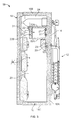
- Figure 3 is a cross-sectional view taken along line 3-3 of Figure 2, with a drawer removed for purposes of illustration.
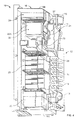
- Figure 4 is a partially cut-away view of a gas absorption refrigerator in accordance with the present disclosure.
- the absorption refrigerator 10 may generally include a cooling system 12 and a cabinet 16 to be cooled by the cooling system 12.
- the cooling system 12 may be mounted in a conventional manner to a back surface 14 of the cabinet 16.
- the cooling system 12 may include various conventional gas absorption cooling components, such as a generator 13, a condenser 15, an evaporator 17, and an absorber 19. An absorption solution flows in the cooling system 12 in a conventional manner.
- the evaporator 17 may include an evaporator tube.
- the evaporator tube may include a first or upstream evaporation portion 21 and a second or downstream evaporation portion 23.
- the cooling system 12 may be controlled electrically or with a gas source in a manner well-known in the art. To the extent not otherwise described herein, it will be understood that the construction and operation of the absorption cooling system 12 is conventional.
- the cabinet 16 may include a rear wall 16A, a top wall 16B, a bottom wall 16C and a pair of side walls 16D (only one side wall is shown in Figure 3).
- the cabinet 16 may be thermally insulated for efficiently maintaining a cooled storage space.
- the refrigerator 10 may include an outer door 18 pivotably mounted to the cabinet 16 for articulation between an open position (as shown in Fig. 2) and a closed position (as shown in Figs. 1, 2 and 4) about an axis A (see Figure 2).
- the outer door is a common door 18. It should be understood and appreciated, however, that more than one door can be used in other applications.
- the axis A may be a vertically extending axis.
- the door 18 cooperates with the walls 16A, 16B, 16C and 16D of the cabinet 16 to define an interior space and selectively provide access to the interior space.
- the interior space of the refrigerator 10 may include a plurality of distinct temperature sections or zones.
- the plurality of distinct temperature sections may include three or more distinct temperature sections.
- the interior space of the refrigerator 10 may define a first section 22, a second section 20 and a third section 24.
- the first section may be a freezer section 22 with a normal temperature setting below a freezing point.
- the freezer section 22 may have a temperature operating range with a median operating temperature.
- the median operating temperature may be approximately -12°C, for example.
- the freezer section 22 may be positioned vertically between the third section 24 and the second section 20. As such, the freezer section 22 may separate the third section 24 and the refrigeration section 20.
- the freezer section 22 may be an enclosed space defined by side walls 22A and a freezer door 22B in order to maintain a freezing temperature inside the freezer section 22.
- the freezer door 22B may be inwardly spaced from the outer door 18 for the refrigerator 10 such that a channel 31 extends therebetween to effectively communicate the third section 24 with the refrigerator section 20.
- the second section may be a refrigeration section 20 and may be disposed below the freezer section 22.
- the refrigeration section 20 may have an operating temperature range above the operating temperature range of the freezer section 22.
- the refrigerator section 20 may have a median setting of approximately 5°C, for example.
- a drawer 25 may be provided in the refrigeration section 20 to create another compartment.
- the third section may be an indirectly cooled 24 section.
- the third section 24 may be disposed above the freezer section 22.
- the third section 24 may have an operating temperature range above the operating temperature ranges of both the freezer section 22 and the second section 20.
- the third section may have a median operating temperature of approximately 13°C, for example.
- the absorption solution (typically including ammonia as a refrigerant and water as an absorbent) is heated in the generator 13 to preferentially release ammonia vapor.
- the ammonia vapor in turn flows out of the generator 13 to the condenser 15.
- the condenser 15 the ammonia vapor cools and condenses. Outside air driven by a fan (not shown) may be employed to provide the heat transfer necessary to condense the vapor in the condenser 15. By gravity, the cool liquid ammonia flows from the condenser 15 and into the evaporator 17.
- the liquid ammonia absorbs heat from the interior of the cabinet 14 of the refrigerator 10 to lower the temperature of the cabinet 14.
- the first evaporation portion 21 is arranged on a back wall of the freezer section 22 and absorbs heat from the freezer section 22 through a first heat transfer plate 27 located therein.
- the second evaporation portion 23 is arranged on a back wall of the refrigeration section 20 and absorbs heat from the refrigeration section 20 through a second heat transfer plate 29 located therein.
- the temperature of the ammonia refrigerant in the first evaporation portion 21 is the lowest. After the ammonia refrigerant passes through the first evaporation portion 21 and flows into the second evaporation portion 23, the temperature of the ammonia refrigerant rises because the ammonia refrigerant has absorbed predominantly heat from the freezer section 22.
- the first evaporation portion 21 functions as the primary source of cooling.
- the vaporized ammonia in the second evaporation portion 23 absorbs heat from the refrigeration section 20.
- the second evaporation portion 23 functions as the residual source of cooling. Thereafter, the vaporized ammonia leaves the second evaporation portion 23 and enters the absorber 19 where the partially depleted water - ammonia mixture absorbs the ammonia vapor to complete the refrigeration cycle.
- the second evaporation portion 23 is preferably disposed at an upper portion of the refrigeration section 20.
- the evaporator 17 does not communicate with the third section 24 of the refrigerator 10. Therefore, the third section 24 is not directly cooled by the evaporator 17. Rather, the third section 24 receives cooling from the refrigeration section 20 through a channel 31 that communicates the third section 24 and the refrigeration section 20 and is thus indirectly cooled by the refrigeration section 20.
- the operating temperature range in the third section 24 may be higher than that in the refrigeration section 20 and the freezer section 22. In certain applications, the operating temperature range of the third section 24 may have a median temperature of approximately 13°C, for example.
- the door 18 of the refrigerator 10 may be provided with one or more shelves.
- the one or more shelves include an upper shelf 26A, a middle shelf 26B and a lower shelf 26C.
- the shelves 26A, 26B, 26C may be injection molded of a plastic material with the remainder of a liner 28 of the door 18.
- the shelves 26A, 26B, 26C may be associated with retention mechanisms 30 for retaining items within the refrigerator 10 while the door 18 is being opened and closed and while the vehicle is in motion.
- the retention mechanisms 30 may be adjustably positioned along horizontally extending bars 32.
- the absorption refrigerator 10 constructed in accordance with the teachings of the present disclosure realizes energy saving and thus can maintain the desired operating temperatures with limited cooling capacity.
- a third section 24 having a higher temperature food such as wine, fruits or vegetables which do not need a low-temperature storage as low as 5°C can be stored in the third section 24.
- the total amount of heat needs to be absorbed by the evaporator 17 to maintain the desired operating temperatures in the cabinet 16 can be reduced, thereby contributing to an energy savings.
- the third section 24 may additionally provide for easy access to the items stored therein as compared with items stored in a drawer which requires a pulling and closing action to provide access.
- Use of the third section 24 instead of a drawer may additionally have an advantage in maintaining freshness of fruits and vegetables.
- ethylene gas is normally given off from various fruits and vegetables during the ripening process. The ethylene gas may facilitate premature deterioration of the fruits and vegetables.
- the third section 24 the ethylene gas will not be trapped in a small closed compartment and will be distributed or otherwise diluted amongst the larger refrigeration section 20 to thereby minimize its adverse effect on the fruits and vegetables.
- the provision of the freezer door 22B inside the cabinet may further contribute to energy saving.
- the freezer door is generally exposed to the outside environment and the heat transfer between the freezer and the outside environment is great due to the significant temperature differences. Therefore, in the prior art refrigerator, the evaporator needs to extract more heat than necessary to compensate for the heat transfer between the freezer section and the outside environment.
- the temperature difference and the heat transfer between the freezer section 22 and the outside environment are reduced, further contributing to energy saving.
Abstract
Description
- This application claims priority to
United States Provisional Patent Application No. 60/752,575 filed December 21, 2005 - The statements in this section merely provide introduction information related to the present disclosure and may not constitute prior art.
- Vehicles, including but not limited to recreational vehicles ("RVs", in the United States and "Caravans" in Europe), tractor trailers, airplanes, boats, trains and the like, often incorporate refrigerators for the comfort and convenience of the occupants. For example, recreational vehicle campers often find it convenient, or even necessary, to refrigerate food, drinks, and medicine during their journey and while at campsites. While many prepared camp sites in parks and commercial campgrounds provide for electrical outlets, many do not. Moreover, many highly desirable camping locations exist outside of these prepared sites. Thus, a popular solution has been to equip the recreational vehicle with a refrigerator such as an absorption refrigerator.
- An absorption refrigerator is a refrigerator that utilizes a heat source to provide the energy needed to drive the cooling system. The cooling system of the absorption refrigerator does not have a compressor or any moving parts, commonly seen in domestic refrigerators, to increase the pressure on the refrigerant gas and force the refrigerant gas to become a refrigerant liquid for another cooling cycle. Instead, the absorption refrigerator is powered by heat, either from electrical heaters or fuel burners, to change the form of the refrigerant. Through evaporation of the refrigerant, heat is absorbed from the refrigerator cabinet to make the cabinet cool.
- More specifically, the absorption refrigerator uses an absorption solution including a refrigerant and an absorbent. Heating the solution releases a portion of the refrigerant from the solution in the form of a vapor. The refrigerant vapor is condensed in a condenser. The refrigerant is then boiled in the evaporator, which removes heat from the refrigerator cabinet and lowers the temperature inside the refrigerator cabinet. The refrigerant vapor is combined back into the solution in the absorber and the combined solution is directed back to the generator for the next cooling cycle.
- There is a need for an absorption refrigerator that efficiently provides for a plurality of cooling zones.
- According to one aspect of the present disclosure, an absorption refrigerator includes a cabinet defining an interior space and an absorption cooling system. The interior space defines a first section maintained at a first operating temperature, a second section maintained at a second operating temperature, and a third section maintained at a third operating temperature. The cooling system includes a first portion for directly absorbing heat from the first section and maintaining the first section at the first operating temperature. The cooling system includes a second portion for directly absorbing heat from the second section and maintaining the second section at the second operating temperature. The second section is in fluid communication with the third section such that the third section receives indirect cooling from the second section.
- According to another aspect of the present disclosure, an absorption refrigerator includes a cabinet and a freezer. The cabinet defines an interior space. The freezer is disposed in the interior space between an upper section and a lower section. The upper and lower sections are in fluid communication with each other adjacent a forward side of the freezer. An absorption cooling system is carried by the cabinet and includes a first portion and a second portion. The first portion directly absorbs head from the freezer section and maintains the freezer section at a first operating temperature, the second portion directly absorbs heat from the lower section and maintains the lower section at a second operating temperature. The second operating temperature is greater than the first operating temperature. The upper section receives indirect cooling from the lower section for maintaining the upper section at a third operating temperature.
- According to still another aspect of the present disclosure, a method of cooling a refrigerator having a cabinet defining an interior space with a first section, a second section and a third section includes attaching an absorption cooling system to the cabinet. The first section is cooled with a primary source of cooling of the absorption cooling system. The second section is cooled with a residual source of cooling of the absorption cooling system. The third section is cooled with an indirect source of cooling from the second section.
- Further areas of applicability of the present invention will become apparent from the detailed description provided hereinafter. It should be understood that the detailed description and specific examples, while indicating the preferred embodiment of the invention, are intended for purposes of illustration only and are not intended to limit the scope of the invention.
- The present invention will become more fully understood from the detailed description and the accompanying drawings, wherein:
- Figure 1 is a front view of a gas absorption refrigerator in accordance with the present disclosure.
- Figure 2 is a perspective view of a gas absorption refrigerator in accordance with the present disclosure, the gas absorption refrigerator illustrated with a door rotated to an open position.
- Figure 3 is a cross-sectional view taken along line 3-3 of Figure 2, with a drawer removed for purposes of illustration.
- Figure 4 is a partially cut-away view of a gas absorption refrigerator in accordance with the present disclosure.
- Corresponding reference numerals indicate corresponding parts throughout the several views of the drawings.
- The following description of the present disclosure will be understood to be merely exemplary in nature and is in no way intended to limit the invention, its application, or uses. In this regard, the various aspects of the present disclosure described herein can be applied to a wide variety of cooling units. For the purpose of illustration, though, an absorption refrigeration system is used. Those skilled in the art will understand that the illustrative refrigeration system should not limit the invention in any way, but is used only to explain the various aspects of the present disclosure.
- With general reference to Figures 1 through 4, an absorption refrigerator in accordance with of the present disclosure is illustrated and generally identified at
reference character 10. Theabsorption refrigerator 10 may generally include acooling system 12 and acabinet 16 to be cooled by thecooling system 12. Thecooling system 12 may be mounted in a conventional manner to aback surface 14 of thecabinet 16. - The
cooling system 12 may include various conventional gas absorption cooling components, such as agenerator 13, acondenser 15, anevaporator 17, and anabsorber 19. An absorption solution flows in thecooling system 12 in a conventional manner. Theevaporator 17 may include an evaporator tube. The evaporator tube may include a first orupstream evaporation portion 21 and a second ordownstream evaporation portion 23. Thecooling system 12 may be controlled electrically or with a gas source in a manner well-known in the art. To the extent not otherwise described herein, it will be understood that the construction and operation of theabsorption cooling system 12 is conventional. - As perhaps shown most clearly in Figures 3 and 4, the
cabinet 16 may include arear wall 16A, atop wall 16B, abottom wall 16C and a pair ofside walls 16D (only one side wall is shown in Figure 3). Thecabinet 16 may be thermally insulated for efficiently maintaining a cooled storage space. - The
refrigerator 10 may include anouter door 18 pivotably mounted to thecabinet 16 for articulation between an open position (as shown in Fig. 2) and a closed position (as shown in Figs. 1, 2 and 4) about an axis A (see Figure 2). As shown, the outer door is acommon door 18. It should be understood and appreciated, however, that more than one door can be used in other applications. The axis A may be a vertically extending axis. Thedoor 18 cooperates with thewalls cabinet 16 to define an interior space and selectively provide access to the interior space. - The interior space of the
refrigerator 10 may include a plurality of distinct temperature sections or zones. The plurality of distinct temperature sections may include three or more distinct temperature sections. As shown throughout the drawings, the interior space of therefrigerator 10 may define afirst section 22, asecond section 20 and athird section 24. - The first section may be a
freezer section 22 with a normal temperature setting below a freezing point. Thefreezer section 22 may have a temperature operating range with a median operating temperature. The median operating temperature may be approximately -12°C, for example. Thefreezer section 22 may be positioned vertically between thethird section 24 and thesecond section 20. As such, thefreezer section 22 may separate thethird section 24 and therefrigeration section 20. Thefreezer section 22 may be an enclosed space defined byside walls 22A and afreezer door 22B in order to maintain a freezing temperature inside thefreezer section 22. Thefreezer door 22B may be inwardly spaced from theouter door 18 for therefrigerator 10 such that achannel 31 extends therebetween to effectively communicate thethird section 24 with therefrigerator section 20. - The second section may be a
refrigeration section 20 and may be disposed below thefreezer section 22. Therefrigeration section 20 may have an operating temperature range above the operating temperature range of thefreezer section 22. Therefrigerator section 20 may have a median setting of approximately 5°C, for example. Adrawer 25 may be provided in therefrigeration section 20 to create another compartment. - The third section may be an indirectly cooled 24 section. The
third section 24 may be disposed above thefreezer section 22. Thethird section 24 may have an operating temperature range above the operating temperature ranges of both thefreezer section 22 and thesecond section 20. The third section may have a median operating temperature of approximately 13°C, for example. - During operation, the absorption solution (typically including ammonia as a refrigerant and water as an absorbent) is heated in the
generator 13 to preferentially release ammonia vapor. The ammonia vapor in turn flows out of thegenerator 13 to thecondenser 15. In thecondenser 15, the ammonia vapor cools and condenses. Outside air driven by a fan (not shown) may be employed to provide the heat transfer necessary to condense the vapor in thecondenser 15. By gravity, the cool liquid ammonia flows from thecondenser 15 and into theevaporator 17. - In the
evaporator 17, the liquid ammonia absorbs heat from the interior of thecabinet 14 of therefrigerator 10 to lower the temperature of thecabinet 14. Thefirst evaporation portion 21 is arranged on a back wall of thefreezer section 22 and absorbs heat from thefreezer section 22 through a firstheat transfer plate 27 located therein. Thesecond evaporation portion 23 is arranged on a back wall of therefrigeration section 20 and absorbs heat from therefrigeration section 20 through a secondheat transfer plate 29 located therein. - The temperature of the ammonia refrigerant in the
first evaporation portion 21 is the lowest. After the ammonia refrigerant passes through thefirst evaporation portion 21 and flows into thesecond evaporation portion 23, the temperature of the ammonia refrigerant rises because the ammonia refrigerant has absorbed predominantly heat from thefreezer section 22. - The
first evaporation portion 21 functions as the primary source of cooling. As the vaporized ammonia flows through thesecond evaporation portion 23, the vaporized ammonia in thesecond evaporation portion 23 absorbs heat from therefrigeration section 20. Thesecond evaporation portion 23 functions as the residual source of cooling. Thereafter, the vaporized ammonia leaves thesecond evaporation portion 23 and enters theabsorber 19 where the partially depleted water - ammonia mixture absorbs the ammonia vapor to complete the refrigeration cycle. Thesecond evaporation portion 23 is preferably disposed at an upper portion of therefrigeration section 20. - The
evaporator 17 does not communicate with thethird section 24 of therefrigerator 10. Therefore, thethird section 24 is not directly cooled by theevaporator 17. Rather, thethird section 24 receives cooling from therefrigeration section 20 through achannel 31 that communicates thethird section 24 and therefrigeration section 20 and is thus indirectly cooled by therefrigeration section 20. The operating temperature range in thethird section 24 may be higher than that in therefrigeration section 20 and thefreezer section 22. In certain applications, the operating temperature range of thethird section 24 may have a median temperature of approximately 13°C, for example. - The
door 18 of therefrigerator 10 may be provided with one or more shelves. In the embodiment illustrated, the one or more shelves include anupper shelf 26A, amiddle shelf 26B and alower shelf 26C. Theshelves liner 28 of thedoor 18. Theshelves retention mechanisms 30 for retaining items within therefrigerator 10 while thedoor 18 is being opened and closed and while the vehicle is in motion. Theretention mechanisms 30 may be adjustably positioned along horizontally extending bars 32. - The
absorption refrigerator 10 constructed in accordance with the teachings of the present disclosure realizes energy saving and thus can maintain the desired operating temperatures with limited cooling capacity. By providing athird section 24 having a higher temperature, food such as wine, fruits or vegetables which do not need a low-temperature storage as low as 5°C can be stored in thethird section 24. As a result, the total amount of heat needs to be absorbed by theevaporator 17 to maintain the desired operating temperatures in thecabinet 16 can be reduced, thereby contributing to an energy savings. - The
third section 24 may additionally provide for easy access to the items stored therein as compared with items stored in a drawer which requires a pulling and closing action to provide access. Use of thethird section 24 instead of a drawer may additionally have an advantage in maintaining freshness of fruits and vegetables. In this regard, ethylene gas is normally given off from various fruits and vegetables during the ripening process. The ethylene gas may facilitate premature deterioration of the fruits and vegetables. By providing thethird section 24, the ethylene gas will not be trapped in a small closed compartment and will be distributed or otherwise diluted amongst thelarger refrigeration section 20 to thereby minimize its adverse effect on the fruits and vegetables. - The provision of the
freezer door 22B inside the cabinet may further contribute to energy saving. In the prior art refrigerator, the freezer door is generally exposed to the outside environment and the heat transfer between the freezer and the outside environment is great due to the significant temperature differences. Therefore, in the prior art refrigerator, the evaporator needs to extract more heat than necessary to compensate for the heat transfer between the freezer section and the outside environment. By providing afreezer door 22B inside thecabinet 16, the temperature difference and the heat transfer between thefreezer section 22 and the outside environment are reduced, further contributing to energy saving. - The description of the invention is merely exemplary in nature and, thus, variations that do now depart from the gist of the invention are intended to be within the scope of the invention. Such variations are not to be regarded as a departure from the spirit and scope of the invention.
Claims (20)
- An absorption refrigerator comprising:a cabinet defining an interior space, the interior space defining:a first section maintained at a first operating temperature;a second section maintained at a second operating temperature;a third section maintained at a third operating temperature; andan absorption cooling system including a first portion and a second portion, the first portion directly absorbing heat from the first section and maintaining the first section at the first operating temperature, the second portion directly absorbing heat from the second section and maintaining the second section at the second operating temperature, the second section being in fluid communication with the third section such that the third section receives indirect cooling from the second section.
- The absorption refrigerator of claim 1, wherein the third section is normally maintained at a temperature greater than the first section and greater than the section.
- The absorption refrigerator of claim 1, wherein the first section is disposed between the second section and the third section, and further wherein the first section is normally maintained at an operating temperature substantially less than the second and third sections.
- The absorption refrigerator of claim 1, wherein the first operating temperature is lower than the second operating temperature, and the second operating temperature is lower than the third operating temperature.
- The absorption refrigerator of claim 1, further comprising an inner door disposed inside the cabinet for selectively providing access to the first section.
- The absorption refrigerator of claim 5, further comprising a common outer door pivotally coupled to the cabinet, the common outer door movable to an open position to provide direct access to the inner door, the first section and the second section.
- The absorption refrigerator of claim 6, further comprising a channel communicating the second section and the third section, the channel disposed between the inner door and the outer door and extending between the second section and the third section.
- The absorption refrigerator of claim 1, wherein the cooling system comprises an evaporator, the evaporator including the first portion and the second portion.
- The absorption refrigerator of claim 8, wherein the first portion is an upstream portion of the evaporator and the second portion is a downstream portion of the evaporator.
- The absorption refrigerator of claim 8, wherein the first portion is a primary source of cooling of the cooling system, and the second portion is a residual source of cooling of the cooling system.
- The absorption refrigerator of claim 1, wherein the third section is positioned at a top of the interior space.
- An absorption refrigerator comprising:a cabinet defining an interior space;a freezer section disposed in the interior space between an upper section and a lower section, the upper section and the lower section being in constant fluid communication with each other adjacent a forward side of the freezer section; andan absorption cooling system carried by the cabinet, the absorption cooling system including a first portion and a second portion, the first portion directly absorbing heat from the freezer section and maintaining the freezer section at a first operating temperature, the second portion directly absorbing heat from the lower section and maintaining the lower section at a second operating temperature, the second operating temperature being greater than the first operating temperature;wherein the upper section receives indirect cooling from the lower section for maintaining the upper section at a third operating temperature.
- The absorption refrigerator of claim 12, wherein the upper section, the first temperature section has a normal operating temperature substantially greater than that of the lower section.
- The absorption refrigerator of claim 12, further comprising a common outer door pivotally attached to the cabinet and an inner door for selectively providing access to the freezer section.
- The absorption refrigerator of Claim 14, further comprising a channel constantly communicating the upper section and the lower section, the channel disposed between the inner door and the outer door.
- The absorption refrigerator of claim 15, wherein the cooling system comprises an evaporator with the first portion for directly absorbing heat from the freezer section and the second portion for directly absorbing heat from the lower section.
- A method of cooling a refrigerator having cabinet defining an interior space with a first section, a second section and a third section, the method including:attaching an absorption cooling system to the cabinet;cooling the first section with a primary source of cooling of the absorption cooling system;cooling the second section with a residual source of cooling of the absorption cooling system; andcooling the third section with an indirect source of cooling from the second section.
- The method of claim 17, wherein cooling the first section with a primary source of cooling of the absorption cooling system includes maintaining the first section at a temperature that is below a temperature of the second section.
- The method of claim 18, wherein cooling the second section with a residual source of cooling of the absorption cooling system includes the step of maintaining the second section at a temperature that is below a temperature of the third section.
- The method of claim 17, wherein cooling the third section with an indirect source of cooling from the second section includes the step of maintaining fluid communication between the second section and the third section.
Applications Claiming Priority (2)
| Application Number | Priority Date | Filing Date | Title |
|---|---|---|---|
| US75257505P | 2005-12-21 | 2005-12-21 | |
| US11/614,549 US20070144204A1 (en) | 2005-12-21 | 2006-12-21 | Gas absorption refrigerator |
Publications (2)
| Publication Number | Publication Date |
|---|---|
| EP1801523A2 true EP1801523A2 (en) | 2007-06-27 |
| EP1801523A3 EP1801523A3 (en) | 2009-04-01 |
Family
ID=38192026
Family Applications (1)
| Application Number | Title | Priority Date | Filing Date |
|---|---|---|---|
| EP06026542A Withdrawn EP1801523A3 (en) | 2005-12-21 | 2006-12-21 | Gas absorption refrigerator |
Country Status (2)
| Country | Link |
|---|---|
| US (1) | US20070144204A1 (en) |
| EP (1) | EP1801523A3 (en) |
Cited By (1)
| Publication number | Priority date | Publication date | Assignee | Title |
|---|---|---|---|---|
| WO2010133069A1 (en) * | 2009-05-19 | 2010-11-25 | 广东奥马电器股份有限公司 | Energy-saving refrigerator |
Families Citing this family (2)
| Publication number | Priority date | Publication date | Assignee | Title |
|---|---|---|---|---|
| DE102010040364A1 (en) * | 2010-09-07 | 2012-03-08 | BSH Bosch und Siemens Hausgeräte GmbH | Interior trim for a refrigerator door |
| US20140182319A1 (en) * | 2012-12-28 | 2014-07-03 | Arlon J. Hunt | Thermal energy storage for temperature regulation in electric vehicles |
Citations (4)
| Publication number | Priority date | Publication date | Assignee | Title |
|---|---|---|---|---|
| US2489752A (en) * | 1944-11-13 | 1949-11-29 | Hoover Co | Refrigeration |
| US2670607A (en) * | 1952-08-16 | 1954-03-02 | Servel Inc | Multiple temperature evaporator |
| US5966951A (en) * | 1997-06-24 | 1999-10-19 | Ab Electrolux | Absorption refrigerator with automatic defrosting |
| WO2005003653A1 (en) * | 2003-07-01 | 2005-01-13 | Dometic Sweden Ab | Absorption refrigerator with ice-maker |
Family Cites Families (14)
| Publication number | Priority date | Publication date | Assignee | Title |
|---|---|---|---|---|
| US2608835A (en) * | 1947-02-28 | 1952-09-02 | Electrolux Ab | Multiple temperature household refrigerator |
| SE317393B (en) * | 1967-06-07 | 1969-11-17 | Electrolux Ab | |
| DE2928774C2 (en) * | 1979-07-17 | 1984-03-22 | Bosch-Siemens Hausgeräte GmbH, 7000 Stuttgart | Freezer with a spacious freezer compartment cooled by natural convection |
| US4711098A (en) * | 1985-10-11 | 1987-12-08 | Sanyo Electric Co., Ltd. | Refrigerator |
| US4879881A (en) * | 1988-09-19 | 1989-11-14 | Madigan Stephen M | Energy efficient frost-free refrigerator |
| US5388427A (en) * | 1992-09-23 | 1995-02-14 | Samsung Electronics Co., Ltd. | Refrigerator with kimchi compartment |
| JP3930206B2 (en) * | 1999-08-06 | 2007-06-13 | 三菱電機株式会社 | Refrigerated refrigerator, cold air circulation method of refrigerator |
| JP3800900B2 (en) * | 1999-09-09 | 2006-07-26 | 三菱電機株式会社 | Refrigerating refrigerator, operation method of freezing refrigerator |
| DE20001253U1 (en) * | 2000-01-25 | 2001-06-07 | Liebherr Hausgeraete | Refrigerator with a refrigerator, a cold storage and a freezer compartment |
| TW507061B (en) * | 2000-05-22 | 2002-10-21 | Matsushita Refrigeration Corp | Refrigerator |
| JP4419347B2 (en) * | 2001-07-13 | 2010-02-24 | 三菱電機株式会社 | Freezer refrigerator |
| US20050022543A1 (en) * | 2003-07-30 | 2005-02-03 | Youngtack Shim | Refrigerators with near-zero compartments |
| US7082783B2 (en) * | 2003-09-19 | 2006-08-01 | U-Line Corporation | Stacked drawer refrigerator |
| US7228704B2 (en) * | 2005-02-28 | 2007-06-12 | U-Line Corporation | Drawer refrigeration unit |
-
2006
- 2006-12-21 US US11/614,549 patent/US20070144204A1/en not_active Abandoned
- 2006-12-21 EP EP06026542A patent/EP1801523A3/en not_active Withdrawn
Patent Citations (4)
| Publication number | Priority date | Publication date | Assignee | Title |
|---|---|---|---|---|
| US2489752A (en) * | 1944-11-13 | 1949-11-29 | Hoover Co | Refrigeration |
| US2670607A (en) * | 1952-08-16 | 1954-03-02 | Servel Inc | Multiple temperature evaporator |
| US5966951A (en) * | 1997-06-24 | 1999-10-19 | Ab Electrolux | Absorption refrigerator with automatic defrosting |
| WO2005003653A1 (en) * | 2003-07-01 | 2005-01-13 | Dometic Sweden Ab | Absorption refrigerator with ice-maker |
Cited By (1)
| Publication number | Priority date | Publication date | Assignee | Title |
|---|---|---|---|---|
| WO2010133069A1 (en) * | 2009-05-19 | 2010-11-25 | 广东奥马电器股份有限公司 | Energy-saving refrigerator |
Also Published As
| Publication number | Publication date |
|---|---|
| US20070144204A1 (en) | 2007-06-28 |
| EP1801523A3 (en) | 2009-04-01 |
Similar Documents
| Publication | Publication Date | Title |
|---|---|---|
| EP3106795B1 (en) | Ice making system and method for a refrigerator | |
| JP4367575B1 (en) | refrigerator | |
| JP4690059B2 (en) | refrigerator | |
| US10036586B2 (en) | Refrigerator | |
| US20090151375A1 (en) | Temperature controlled compartment and method for a refrigerator | |
| JP4867758B2 (en) | refrigerator | |
| US3914957A (en) | Fast cooling liquid dispensing container accessory for refrigerators | |
| US20210239382A1 (en) | Refrigerator | |
| TWI343467B (en) | ||
| JP2007024339A (en) | Refrigerator | |
| EP1801523A2 (en) | Gas absorption refrigerator | |
| US11067328B2 (en) | Hybrid cooling appliance | |
| KR101404342B1 (en) | Refrigerator | |
| KR200320682Y1 (en) | A cold-storing shelf of a refrigerator, and a portable ice box using thereof | |
| JP2004361039A (en) | Freezing refrigerator | |
| CN100374796C (en) | Kimchi refrigerator with fast cooling function | |
| KR100664490B1 (en) | Refrigerator | |
| US10132544B2 (en) | Ice-making device for refrigerator | |
| JP3722148B1 (en) | refrigerator | |
| CN219913610U (en) | Refrigerator with a refrigerator body | |
| CN115479428B (en) | Refrigerating and freezing device and installation method thereof | |
| CN210832685U (en) | Refrigerator with a door | |
| KR200302405Y1 (en) | Heat exchanger structure of kim-chi storage with direct cooling type | |
| KR0143590B1 (en) | Cooling and heating system for an automobile | |
| KR20040058886A (en) | Dispenser in refrigerator |
Legal Events
| Date | Code | Title | Description |
|---|---|---|---|
| PUAI | Public reference made under article 153(3) epc to a published international application that has entered the european phase |
Free format text: ORIGINAL CODE: 0009012 |
|
| AK | Designated contracting states |
Kind code of ref document: A2 Designated state(s): AT BE BG CH CY CZ DE DK EE ES FI FR GB GR HU IE IS IT LI LT LU LV MC NL PL PT RO SE SI SK TR |
|
| AX | Request for extension of the european patent |
Extension state: AL BA HR MK YU |
|
| PUAL | Search report despatched |
Free format text: ORIGINAL CODE: 0009013 |
|
| AK | Designated contracting states |
Kind code of ref document: A3 Designated state(s): AT BE BG CH CY CZ DE DK EE ES FI FR GB GR HU IE IS IT LI LT LU LV MC NL PL PT RO SE SI SK TR |
|
| AX | Request for extension of the european patent |
Extension state: AL BA HR MK RS |
|
| AKX | Designation fees paid | ||
| STAA | Information on the status of an ep patent application or granted ep patent |
Free format text: STATUS: THE APPLICATION IS DEEMED TO BE WITHDRAWN |
|
| 18D | Application deemed to be withdrawn |
Effective date: 20091002 |
|
| REG | Reference to a national code |
Ref country code: DE Ref legal event code: 8566 |