EP1801496A2 - Shielding arrangement of the smelt spout area of a recovery boiler - Google Patents
Shielding arrangement of the smelt spout area of a recovery boiler Download PDFInfo
- Publication number
- EP1801496A2 EP1801496A2 EP06397016A EP06397016A EP1801496A2 EP 1801496 A2 EP1801496 A2 EP 1801496A2 EP 06397016 A EP06397016 A EP 06397016A EP 06397016 A EP06397016 A EP 06397016A EP 1801496 A2 EP1801496 A2 EP 1801496A2
- Authority
- EP
- European Patent Office
- Prior art keywords
- smelt
- shielding
- shielding wall
- area
- recovery boiler
- Prior art date
- Legal status (The legal status is an assumption and is not a legal conclusion. Google has not performed a legal analysis and makes no representation as to the accuracy of the status listed.)
- Granted
Links
Images


Classifications
-
- D—TEXTILES; PAPER
- D21—PAPER-MAKING; PRODUCTION OF CELLULOSE
- D21C—PRODUCTION OF CELLULOSE BY REMOVING NON-CELLULOSE SUBSTANCES FROM CELLULOSE-CONTAINING MATERIALS; REGENERATION OF PULPING LIQUORS; APPARATUS THEREFOR
- D21C11/00—Regeneration of pulp liquors or effluent waste waters
- D21C11/12—Combustion of pulp liquors
-
- D—TEXTILES; PAPER
- D21—PAPER-MAKING; PRODUCTION OF CELLULOSE
- D21C—PRODUCTION OF CELLULOSE BY REMOVING NON-CELLULOSE SUBSTANCES FROM CELLULOSE-CONTAINING MATERIALS; REGENERATION OF PULPING LIQUORS; APPARATUS THEREFOR
- D21C11/00—Regeneration of pulp liquors or effluent waste waters
- D21C11/12—Combustion of pulp liquors
- D21C11/122—Treatment, e.g. dissolution, of the smelt
-
- F—MECHANICAL ENGINEERING; LIGHTING; HEATING; WEAPONS; BLASTING
- F22—STEAM GENERATION
- F22B—METHODS OF STEAM GENERATION; STEAM BOILERS
- F22B37/00—Component parts or details of steam boilers
- F22B37/02—Component parts or details of steam boilers applicable to more than one kind or type of steam boiler
- F22B37/48—Devices or arrangements for removing water, minerals or sludge from boilers ; Arrangement of cleaning apparatus in boilers; Combinations thereof with boilers
Definitions
- the basic idea of the invention is to arrange a shielding wall in front of the smelt spouts, which can be moved, for example closed and opened.
- the closed shielding wall settles between the person working in the working area and the smelt spout.
- the shielding wall prevents the possible smelt splashes from falling on the person.
- the shielding wall also muffles the noise from the smelt spouts towards the working area.
- the heat radiation radiated from the smelt spouts to the working area is dampened by the shielding wall.
- the shielding wall 8 may application-specifically be located on different sides of the boiler (on one or more sides). In a power plant application the shielding wall 8 is on those sides of the boiler where the smelt spouts 2 are located. In another power plant application the shielding wall 8 is placed around the boiler.
Landscapes
- Engineering & Computer Science (AREA)
- Physics & Mathematics (AREA)
- Thermal Sciences (AREA)
- Mechanical Engineering (AREA)
- General Engineering & Computer Science (AREA)
- Waste-Gas Treatment And Other Accessory Devices For Furnaces (AREA)
- Paper (AREA)
- Catching Or Destruction (AREA)
- Casting Support Devices, Ladles, And Melt Control Thereby (AREA)
- Gasification And Melting Of Waste (AREA)
Abstract
Description
- The invention relates to a method for improving the operation safety of the smelt spout area of a recovery boiler according to the preamble of the appended
claim 1, and the smelt spout area of a recovery boiler according to the preamble of the appendedclaim 6. - The spent lye, i.e. the so-called black liquor created in pulp manufacture is burnt in a recovery boiler, on one hand, in order to recover the energy it includes, and on the other hand, in order to recover the chemicals in it and to recycle them back to circulation. A char bed is created on the bottom of the recovery boiler when burning black liquor, which in a high temperature forms into smelt, which is removed from the boiler as a continuous flow via smelt spouts to a dissolving tank.
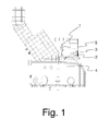
- Below the furnace is located the cover area of the dissolving tank of the recovery boiler, i.e. the smelt spout area, where the smelt from the lower part of the furnace is directed along the so-called smelt spout to the dissolving tank. Figure 1 shows a typical smelt spout area of a recovery boiler, which comprises
smelt spouts 2, along which the smelt is directed from thefurnace 3 to the dissolvingtank 4. - It is necessary to work in the vicinity of the smelt spouts relatively often, because the operation of the smelt spouts must be monitored at regular intervals. When necessary, pluggings must be removed from the smelt spouts in order for the smelt to be able to travel to the dissolving tank. In addition, the
primary air nozzles 5 are often located in the vicinity of the smelt spout area (on the so-called primary register level), in which case checking and adjusting the nozzles requires working in the smelt spout area. - Typically, the smelt is very hot (for example 750 to 820 °C). The possible splashes of smelt cause danger to the personnel working and moving in the vicinity. Because of this, there is typically a protection area near the smelt spouts, moving on which area should be avoided and working on which area requires using special protection equipment.
- The main purpose of the present invention is to disclose a new solution for increasing work safety.
- To attain this purpose, the method according to the invention is primarily characterized in what will be presented in the characterizing part of the
independent claim 1. The smelt spout area of a recovery boiler according to the invention, in turn, is primarily characterized in what will be presented in the characterizing part of theindependent claim 6. The other, dependent claims will present some preferred embodiments of the invention. - The basic idea of the invention is to arrange a shielding wall in front of the smelt spouts, which can be moved, for example closed and opened. According to the basic idea the closed shielding wall settles between the person working in the working area and the smelt spout. The shielding wall prevents the possible smelt splashes from falling on the person. In an advantageous embodiment the shielding wall also muffles the noise from the smelt spouts towards the working area. In an embodiment the heat radiation radiated from the smelt spouts to the working area is dampened by the shielding wall.
- The method according to the invention discloses a solution for improving the operation safety of the smelt spout area of a recovery boiler, which smelt spout area comprises a working area, as well as smelt spouts connected to the lower part of the boiler to direct the smelt from the boiler to a dissolving tank. In the method, the smelt spouts are separated from the working area by a shielding wall that is arranged movable in relation to the smelt spouts. Correspondingly, in a power plant according to the invention, the smelt spout area comprises one or more shielding walls arranged movable in relation to the smelt spout in order to separate the smelt spouts from the working area.
- In an embodiment the shielding wall is formed of one or more shielding units arranged movable. The shielding units can move in different directions application-specifically, such as, for example horizontally or vertically.
- The movable shielding wall enables different usage, service and maintenance operations requiring a great deal of moving space. In an advantageous embodiment the shielding wall can be opened for a large uniform length.
- The shielding wall can be implemented in a variety of ways. Advantageously the wall is formed of several units, in which case handling it is easier than handling large units. For example, the wall may be composed of sliding doors, lattice doors, shutters and/or folding doors. The direction of motion of individual units of the wall depends on the application. For example, the direction of motion can be horizontal or vertical. The wall can also move parallel or perpendicularly in relation to the bank of smelt spouts of the boiler.
- In an embodiment the smelt spout area also comprises a service platform arranged movable in relation to the smelt spouts, which platform comprises a shielding wall. The service platform is meant for the usage, service and maintenance operations of targets located higher, such as the primary register level.
- The shielding wall advantageously comprises inspection openings, such as, for example, windows and/or hatches that can be opened, through which it is possible to perform, inter alia, visual monitoring, rodding the spouts, as well as other usage, service and maintenance operation. There can be different kinds and shapes of hatches and windows, which provide as optimal as possible user interfaces for different tasks.
- By the solution according to the invention, many significant advantages are achieved when compared with the solutions of prior art. The safety of the smelt spout area of a recovery boiler is improved, when the shielding structure separates the smelt spouts from the personnel. The shielding structure can application-specifically prevent different splashes, steams and/or pressure shocks from reaching the working area.
- In an application the noise level of the smelt spout area is decreased. Muffling the noise is affected by the design and materials of the shielding structure. Decreased noise level improves work conditions and increases work safety for its part.
- In one case the invention, in turn, enables the efficient utilization of the smelt spout area, because the shielding area can be decreased due to the shielding solution and the area that is thus freed can be used efficiently.
- In the following, the invention will be described in more detail with reference to the appended principle drawings, in which
- Fig. 1
- shows a smelt spout area according to prior art,
- Fig. 2
- shows a side view of a smelt spout area according to the invention,
- Fig. 3
- shows a front view of a shielding wall unit according to the invention,
- Fig.4
- shows a front view of a shielding wall according to the invention,
- Fig. 5
- shows the shielding wall of Figure 4 along line A-A.
- For the sake of clarity, the figures only show the details necessary for understanding the invention. The structures and details that are not necessary for understanding the invention, but are obvious for anyone skilled in the art, have been omitted from the figures in order to emphasize the characteristics of the invention.
- Figure 1 shows a present smelt spout area of a recovery boiler. The area comprises
smelt spouts 2, along which the smelt is directed from thefurnace 3 to the dissolvingtank 4. Generally in boilers theair nozzles 5 of the primary air level are placed above thesmelt spouts 2 in such a manner that they can be accessed from the smelt spout area, for example, by means of some platform. - Figure 2 shows the shielding
wall 8 according to the invention in a side view. This direction is the same as the direction of the bank of smelt spouts 2, i.e. the direction of the wall of the boiler. The shieldingwall 8 is arranged between the workingarea 6 and the smelt spouts 2. The workingarea 6 refers to that area of the smelt spout area, where the personnel works when performing usage, service and maintenance operation. In the case according to figure 2, the workingarea 6 is the area to the left of the shieldingwall 8. In figure 2, inter alia, aservice platform 7 is located in the workingarea 6, which platform forms its own, smaller working area. As can be seen in figure 2, the shieldingwall 8 protects theperson 1 on the workingarea 6 by separating the person from a direct contact with the smeltspout 2. - Figure 3 shows a shielding unit 9 (shielding module, shielding element) forming the shielding
wall 8 in a front view, i.e. when the viewing direction is from the workingarea 6 towards the smelt spouts 2. In the example, theshielding unit 9 of the shieldingwall 8 comprises twowindows lower window 12 can be opened and closed, and it enables performing the often repeated usage, service and maintenance operation, such as rodding, without having to move the shieldingwall 8 to the side. Thanks to thewindows shielding wall 8 does not need to be opened for visual inspection. Thus, the inspection can be performed from a protected space. There may be several hatches and/orwindows wall 8, or not necessarily any windows and/or hatches at all. The hatches can comprise windows or be solid, depending on the target of use. For example, the shieldingwall 8 may comprise a hatch for working and a window for camera monitoring. - Figure 4 shows an application, where the shielding
wall 8 comprises severaladjacent shielding units 9 shown in figure 3. The shieldingwall 8 can comprise one ormore shielding units 9. In the example, the shieldingunits 9 of the shieldingwall 8 are certain kind of sliding doors, which can be slid in the direction of the boiler wall. For this purpose there areslide rails 13 at the bottom and top, which enable the sliding. Advantageously there are severaladjacent rails 13, such as, for example, three or four rails, in which case when opening the wall it is possible to slide several doors adjacently into a bundle and thus form a larger opening. This has been aimed to be illustrated in figure 5, which shows the application of figure 4 in a top view along line A-A. - By opening the shielding
wall 8 partly or entirely is created a large and as clear as possible passage to the area behind the line formed by the shieldingwall 8, such as, for example, to the smelt spouts 2. Thus, it is easier to perform more extensive usage, service and maintenance operation. As can be seen in figure 5, the opening of the shieldingwall 8 can be performed by moving the shieldingunits 9 along therails 13. The shieldingunits 9 ondifferent rails 13 can be mutually placed in such a manner that the second shielding unit is located behind the first shielding unit. The details connected to opening and closing the shieldingwall 8 naturally depend on the structure of the shielding wall. The opening and closing may, for example, be based on overlapping, folding and/or removing. - In an application the attachment of the
shielding unit 9 of the shieldingwall 8 is arranged with a quick clamping, which enables the easy and fast detachment, and if necessary, the removal and/or changing of the shielding unit. - The shielding
wall 8 may application-specifically be located on different sides of the boiler (on one or more sides). In a power plant application theshielding wall 8 is on those sides of the boiler where the smelt spouts 2 are located. In another power plant application theshielding wall 8 is placed around the boiler. - The structure of the shielding
wall 8 and theindividual shielding units 9 may vary application-specifically. Some possible solutions include different kinds of sliding doors, lattice doors, folding doors, roller shutters, etc. In addition, the direction of motion of the shieldingunits 9 may vary application-specifically. In the previous example the direction of motion of the shieldingunits 9 is horizontal and in the direction of the boiler wall. In another application the direction of motion of theshielding unit 9 is substantially perpendicular to the boiler wall. In an application the direction of motion of theshielding unit 9 is substantially vertical. In an application the direction of motion of the movement taking place vertically is, in turn, slanted. Especially different curtain-type shielding walls 8 are advantageous to be arranged to move upwards, preferably vertically if possible, in which case the structure does not necessarily have to be rigid in order to control the movement of the shieldingwall 8. The movement of the shieldingwall 8 can also be controlled by different solutions, such as, for example, rolls, glides, guide bars, hinges and junction structures. - In selecting the material for the shielding
wall 8 it is advantageous to pay attention to, inter alia, thermal resistance and the resistance of the occurring chemicals. The shieldingwall 8 should be incombustible and preferably sound-insulating. Because of ease of processing theshielding units 9 of the shieldingwall 8 should be light, which, in addition to the materials, is affected by the size and shape of the shielding unit. In some tests ashielding wall 8 manufactured of stainless steel has been detected to be useful. Its sound-insulation can be improved with different sound-insulating materials. There are also other alternatives, such as, for example structures manufacture entirely or partly of metal, composite or ceramic. - The shielding
wall 8 must also endure great temperature fluctuations, which occur, inter alia, in connection with the start-up and shutdown of the boiler. Thermal radiation of the boiler causes the dimensions of the shieldingwall 8 to change. In addition, a change in the temperature of the shieldingwall 8 causes the dimensions to change in its structure. For easy handling the shieldingwall 8 must enable the thermal expansion of both the shielding wall and other structures. The changes caused by thermal expansion affecting the shieldingwall 8 may be several tens of centimeters in size. The shieldingwall 8 can, for example, be implemented in such a manner that its structure is flexible or its structure increases and decreases according to need. It is also possible that the attachment solution enables thermal radiation. - The space around the boiler defined by the shielding wall can be substantially solid or breathing. A breathing structure can be implemented in a variety of ways. The shielding
wall 8 can, for example, be formed in such a manner that air can flow between the shieldingunits 9 of the shielding wall. It is also possible to use different breather and valve structures for pressure balancing. The flow of air and other gases can also be controlled with various types of channel structures. For example, a pipe can be lead to the outside from the space defined around the boiler by the shieldingwall 8. Different pressure shocks may occur in the space in question, for example, when a malfunction is created in the smeltspout 2, such as, for example, a smelt flush. - Figures 2 and 4 show a
service platform 7 as well. In the example, theservice platform 7 is intended for the usage, service and maintenance operation of the so-called primary register level. In the example according to the figure, the primary register level is above the smelt spouts 2 and it comprises, inter alia,primary air nozzles 5. Theservice platform 7 is arranged to be movable. In the example, theservice platform 7 comprises wheels, which are located in therails 14 in the floor. The path of theservice platform 7 is controlled by means of therails 14. It is also possible to arrange theservice platform 7 to be movable in another manner. Moving theservice platform 7 and/or the shieldingwall 8 may application-specifically take place either manually and/or with engine power, such as, for example, by electric motor usage. - The shielding
wall 8 described above protects theperson 1 on theservice platform 7. It is also possible to arrange a shieldingwall 10 in connection with theservice platform 7. Thus, the shieldingwall 10 moves along with theservice platform 7 always being between the working area of the service platform and the smelt spouts 2, thus protecting the working area. The shieldingwall 10 of thisservice platform 7 can also be equipped with different hatches and windows, for example, as has been described above. The size and appearance of the shieldingwall 10 of the service platform may vary depending on the target of use. - The shielding effect of the shielding
wall 8, as well as work safety can be improved by arranging the devices in the smelt spout area in advantageous positions. By designing theprimary air nozzles 5 for example smaller, the working position is made safer and more ergonomic. As can be seen in figure 2, by arranging the first side of the air nozzle 5 (the side opposite to the side connected to the furnace) close to the vertical line formed by the shieldingwall 8, theperson 1 does not have to reach as much as in solutions of prior art. - By combining, in various ways, the modes and structures disclosed in connection with the different embodiments of the invention presented above, it is possible to produce various embodiments of the invention in accordance with the spirit of the invention. Therefore, the above-presented examples must not be interpreted as restrictive to the invention, but the embodiments of the invention may be freely varied within the scope of the inventive features presented in the claims hereinbelow.
Claims (13)
- A method for improving the operation safety of the smelt spout area of a recovery boiler, which smelt spout area comprises a working area (6), as well as smelt spouts (2) connected to the lower part of the boiler for directing the smelt from the boiler to a dissolving tank (4),
characterized in that in the method the smelt spouts (2) are separated from the working area (6) by a shielding wall (8, 10) arranged movable in relation to the smelt spouts. - The method according to claim 1, characterized in that the shielding wall (8, 10) is formed of one or more shielding units (9) arranged movable.
- The method according to claim 2, characterized in that the shielding unit (9) is arranged horizontally movable.
- The method according to claim 2, characterized in that the shielding unit (9) is arranged vertically movable.
- The method according to claim 1 or 2, characterized in that the shielding wall (10) is placed on a service platform (7), which is arranged movable in relation to the smelt spouts (2).
- A smelt spout area of a recovery boiler, which comprises a working area (6), as well as smelt spouts (2) connected to the lower part of the boiler for directing the smelt from the boiler to a dissolving tank (4),
characterized in that the smelt spout area comprises one or more shielding walls (8) arranged movable in relation to the smelt spout (2) in order to separate the smelt spouts from the working area (6). - The smelt spout area of a recovery boiler according to claim 6,
characterized in that the shielding wall (8, 10) is formed of one or more shielding units (9) arranged movable. - The smelt spout area of a recovery boiler according to claim 7,
characterized in that the shielding unit (9) is arranged horizontally movable. - The smelt spout area of a recovery boiler according to claim 7,
characterized in that the shielding unit (9) is arranged vertically movable. - The smelt spout area of a recovery boiler according to any of the preceding claims 6 to 9, characterized in that the shielding wall (8, 10) is formed of one or more shielding units (9), which is at least one of the following: a sliding door, a lattice door, a folding door, a roller shutter.
- The smelt spout area of a recovery boiler according to claim 6 or 7,
characterized in that the smelt spout area in addition comprises a service platform (7) arranged movable in relation to the smelt spouts (2), which service platform comprises a shielding wall (10). - The smelt spout area of a recovery boiler according to any of the preceding claims 6 to 11, characterized in that the shielding wall (8, 10) comprises one or more windows (11, 12).
- The smelt spout area of a recovery boiler according to any of the preceding claims 6 to 12, characterized in that the shielding wall (8, 10) comprises one or more hatches (12) that can be opened and closed.
Priority Applications (1)
| Application Number | Priority Date | Filing Date | Title |
|---|---|---|---|
| PL06397016T PL1801496T3 (en) | 2005-08-11 | 2006-08-03 | Shielding arrangement of the smelt spout area of a recovery boiler |
Applications Claiming Priority (1)
| Application Number | Priority Date | Filing Date | Title |
|---|---|---|---|
| FI20055432A FI121313B2 (en) | 2005-08-11 | 2005-08-11 | Protective arrangement for a smelting area of a soda boiler |
Publications (3)
| Publication Number | Publication Date |
|---|---|
| EP1801496A2 true EP1801496A2 (en) | 2007-06-27 |
| EP1801496A3 EP1801496A3 (en) | 2007-07-04 |
| EP1801496B1 EP1801496B1 (en) | 2015-09-30 |
Family
ID=34896332
Family Applications (1)
| Application Number | Title | Priority Date | Filing Date |
|---|---|---|---|
| EP06397016.4A Revoked EP1801496B1 (en) | 2005-08-11 | 2006-08-03 | Shielding arrangement of the smelt spout area of a recovery boiler |
Country Status (8)
| Country | Link |
|---|---|
| US (2) | US7900567B2 (en) |
| EP (1) | EP1801496B1 (en) |
| BR (1) | BRPI0603338B1 (en) |
| CA (1) | CA2555929A1 (en) |
| ES (1) | ES2556934T3 (en) |
| FI (1) | FI121313B2 (en) |
| PL (1) | PL1801496T3 (en) |
| PT (1) | PT1801496E (en) |
Cited By (1)
| Publication number | Priority date | Publication date | Assignee | Title |
|---|---|---|---|---|
| WO2013171379A1 (en) * | 2012-05-16 | 2013-11-21 | Andritz Oy | Recovery boiler plant of a chemical pulp mill |
Families Citing this family (1)
| Publication number | Priority date | Publication date | Assignee | Title |
|---|---|---|---|---|
| FI122899B (en) * | 2006-10-16 | 2012-08-31 | Metso Power Oy | Cleaner for the soda boiler |
Family Cites Families (21)
| Publication number | Priority date | Publication date | Assignee | Title |
|---|---|---|---|---|
| US654516A (en) * | 1899-04-15 | 1900-07-24 | Pittsburg Foundry And Machine Company | Shield for furnaces. |
| DE343072C (en) | 1920-03-03 | 1921-10-27 | Edgar E Brosius | Device for loading and emptying crucible furnaces |
| US1640663A (en) * | 1927-02-09 | 1927-08-30 | Mauthe James Lester | Splasher plate for blast furnaces |
| US3215099A (en) * | 1962-08-28 | 1965-11-02 | Babcock & Wilcox Co | Chemical and heat recovery apparatus |
| US3580556A (en) * | 1968-04-18 | 1971-05-25 | Bethlehem Steel Corp | Safety shield for a fume-collecting apparatus |
| US4269901A (en) * | 1979-08-07 | 1981-05-26 | Chamberlain Francis N | Device for protection against fire |
| US4479637A (en) * | 1982-09-01 | 1984-10-30 | National Steel Corporation | Apparatus for and method of repairing bottom lining of a converter |
| US4761204A (en) * | 1987-01-30 | 1988-08-02 | Rockwell International Corporation | Chemical recovery process using break up steam control to prevent smelt explosions |
| JPH02264091A (en) | 1989-04-04 | 1990-10-26 | Mitsubishi Heavy Ind Ltd | Apparatus for cleaning air intake of recovery boiler |
| US4867677A (en) * | 1989-05-03 | 1989-09-19 | Bethlehem Steel Corporation | Curtain door for metal reheating furnace |
| US5357664A (en) * | 1993-10-06 | 1994-10-25 | Donnelly James N | Curtain apparatus |
| US5640747A (en) * | 1993-10-06 | 1997-06-24 | Donnelly; James N. | Curtain apparatus |
| US5542650A (en) | 1995-02-10 | 1996-08-06 | Anthony-Ross Company | Apparatus for automatically cleaning smelt spouts of a chemical recovery furnace |
| FI2933U1 (en) | 1996-12-20 | 1997-06-10 | Ahlstrom Machinery Oy | Arrangement in connection with the recovery boiler melt chute |
| JPH1123769A (en) | 1997-07-03 | 1999-01-29 | Ishikawajima Harima Heavy Ind Co Ltd | Shielding device around nozzle of reactor pressure vessel |
| BE1014317A4 (en) | 2001-07-26 | 2003-08-05 | Houtconstructies Wyckaert Nv | Motor driven fireproof sliding door, has heat shield extending parallel to and located in front of runner rail |
| SE522148C2 (en) | 2002-05-03 | 2004-01-20 | Sodahus Teknik Iggesund Ab | Robot for cleaning a running chute included in a soda pan |
| CA2440788C (en) | 2003-09-12 | 2012-01-03 | Jean-Paul Fredette | Motorized scaffold with displaceable worker support platform |
| FI122814B (en) * | 2005-01-17 | 2012-07-13 | Andritz Oy | Procedure and arrangement in connection with a chemical recovery boiler |
| US7686405B2 (en) * | 2005-04-20 | 2010-03-30 | True Manufacturing Co., Inc. | Self-closing sliding door assembly |
| US7735435B2 (en) * | 2006-05-24 | 2010-06-15 | Diamond Power International, Inc. | Apparatus for cleaning a smelt spout of a combustion device |
-
2005
- 2005-08-11 FI FI20055432A patent/FI121313B2/en active IP Right Grant
-
2006
- 2006-08-03 EP EP06397016.4A patent/EP1801496B1/en not_active Revoked
- 2006-08-03 PL PL06397016T patent/PL1801496T3/en unknown
- 2006-08-03 PT PT63970164T patent/PT1801496E/en unknown
- 2006-08-03 ES ES06397016.4T patent/ES2556934T3/en active Active
- 2006-08-09 CA CA002555929A patent/CA2555929A1/en not_active Abandoned
- 2006-08-10 BR BRPI0603338A patent/BRPI0603338B1/en not_active IP Right Cessation
- 2006-08-11 US US11/502,441 patent/US7900567B2/en active Active
-
2011
- 2011-02-18 US US13/030,294 patent/US20110140317A1/en not_active Abandoned
Cited By (4)
| Publication number | Priority date | Publication date | Assignee | Title |
|---|---|---|---|---|
| WO2013171379A1 (en) * | 2012-05-16 | 2013-11-21 | Andritz Oy | Recovery boiler plant of a chemical pulp mill |
| CN104302832A (en) * | 2012-05-16 | 2015-01-21 | 安德里兹公司 | Recovery boiler plant of a chemical pulp mill |
| US9562323B2 (en) | 2012-05-16 | 2017-02-07 | Andritz Oy | Recovery boiler plant of a chemical pulp mill |
| CN104302832B (en) * | 2012-05-16 | 2018-05-08 | 安德里兹公司 | The recovery boiler equipment of chemical pulp mills |
Also Published As
| Publication number | Publication date |
|---|---|
| EP1801496B1 (en) | 2015-09-30 |
| PT1801496E (en) | 2016-01-08 |
| US7900567B2 (en) | 2011-03-08 |
| FI20055432L (en) | 2007-02-12 |
| FI121313B (en) | 2010-09-30 |
| US20070036695A1 (en) | 2007-02-15 |
| EP1801496A3 (en) | 2007-07-04 |
| ES2556934T3 (en) | 2016-01-21 |
| US20110140317A1 (en) | 2011-06-16 |
| FI121313B2 (en) | 2015-06-10 |
| BRPI0603338A (en) | 2007-03-27 |
| FI20055432A0 (en) | 2005-08-11 |
| CA2555929A1 (en) | 2007-02-11 |
| PL1801496T3 (en) | 2016-03-31 |
| BRPI0603338B1 (en) | 2015-12-22 |
Similar Documents
| Publication | Publication Date | Title |
|---|---|---|
| CA2606735C (en) | Cleaner for the smelt spout of a recovery boiler | |
| US5623918A (en) | Inducer condensate channel | |
| US20110140317A1 (en) | Shielding arrangement for the smelt spout area of a recovery boiler | |
| CA2937947C (en) | Startup burner assembly for recovery boiler and method | |
| CN210430549U (en) | Low-voltage distribution cabinet with adjustable internally mounted skeleton | |
| CN115297654A (en) | Protector for electric controller | |
| CA2870838C (en) | Recovery boiler plant of a chemical pulp mill | |
| JP5303563B2 (en) | Cleaning device for coke oven chamber frame | |
| CN114058775B (en) | Multi-section expansion flue of waste heat boiler | |
| DE202023102088U1 (en) | Exhaust air device and cooking device with the same | |
| CN222235185U (en) | Unmanned on duty control cabinet of protection machanism and bucket wheel machine body | |
| EP0991898A1 (en) | Wind box for a chemical recovery furnace | |
| KR200383496Y1 (en) | Protection case of former | |
| CN220479605U (en) | Self-circulation tray cleaning system | |
| DE102011015497B4 (en) | Arrangement for shielding a post-combustion grate in a steam boiler of a power plant | |
| KR101104974B1 (en) | Waste gas furnace switchgear | |
| DE202023102325U1 (en) | Exhaust device and cooking device with the same | |
| DE202023102328U1 (en) | Exhaust device and cooking device with the same | |
| EA012894B1 (en) | UNIT OF SERVICE OF THE COKE OVEN WITH THE ASPIRATION DEVICE FOR DRAINING EMISSIONS | |
| CN115574356A (en) | Integrated smallpox petticoat pipe of assembled | |
| WO2001061248A1 (en) | Arrangement for cleaning, airflow control and pushing away melt in air ports of incineration boilers | |
| US20060150873A1 (en) | Slot-port system | |
| EP3001105B1 (en) | Oven with a translucent pane | |
| EP1813885A2 (en) | Boiler with silencer | |
| DD292309A5 (en) | ARRANGEMENT FOR DISTRIBUTION OF FUEL CHAMBER AND EXHAUST GAS SUPPLIES OF STEAM BOILERS |
Legal Events
| Date | Code | Title | Description |
|---|---|---|---|
| PUAI | Public reference made under article 153(3) epc to a published international application that has entered the european phase |
Free format text: ORIGINAL CODE: 0009012 |
|
| PUAL | Search report despatched |
Free format text: ORIGINAL CODE: 0009013 |
|
| AK | Designated contracting states |
Kind code of ref document: A2 Designated state(s): AT BE BG CH CY CZ DE DK EE ES FI FR GB GR HU IE IS IT LI LT LU LV MC NL PL PT RO SE SI SK TR |
|
| AX | Request for extension of the european patent |
Extension state: AL BA HR MK YU |
|
| AK | Designated contracting states |
Kind code of ref document: A3 Designated state(s): AT BE BG CH CY CZ DE DK EE ES FI FR GB GR HU IE IS IT LI LT LU LV MC NL PL PT RO SE SI SK TR |
|
| AX | Request for extension of the european patent |
Extension state: AL BA HR MK YU |
|
| 17P | Request for examination filed |
Effective date: 20071207 |
|
| AKX | Designation fees paid |
Designated state(s): AT BE BG CH CY CZ DE DK EE ES FI FR GB GR HU IE IS IT LI LT LU LV MC NL PL PT RO SE SI SK TR |
|
| RAP1 | Party data changed (applicant data changed or rights of an application transferred) |
Owner name: METSO POWER OY |
|
| RAP1 | Party data changed (applicant data changed or rights of an application transferred) |
Owner name: VALMET POWER OY |
|
| RAP1 | Party data changed (applicant data changed or rights of an application transferred) |
Owner name: VALMET TECHNOLOGIES OY |
|
| GRAP | Despatch of communication of intention to grant a patent |
Free format text: ORIGINAL CODE: EPIDOSNIGR1 |
|
| INTG | Intention to grant announced |
Effective date: 20150515 |
|
| GRAS | Grant fee paid |
Free format text: ORIGINAL CODE: EPIDOSNIGR3 |
|
| GRAA | (expected) grant |
Free format text: ORIGINAL CODE: 0009210 |
|
| AK | Designated contracting states |
Kind code of ref document: B1 Designated state(s): AT BE BG CH CY CZ DE DK EE ES FI FR GB GR HU IE IS IT LI LT LU LV MC NL PL PT RO SE SI SK TR |
|
| REG | Reference to a national code |
Ref country code: CH Ref legal event code: EP Ref country code: GB Ref legal event code: FG4D |
|
| REG | Reference to a national code |
Ref country code: AT Ref legal event code: REF Ref document number: 752641 Country of ref document: AT Kind code of ref document: T Effective date: 20151015 |
|
| REG | Reference to a national code |
Ref country code: IE Ref legal event code: FG4D |
|
| REG | Reference to a national code |
Ref country code: DE Ref legal event code: R096 Ref document number: 602006046796 Country of ref document: DE |
|
| REG | Reference to a national code |
Ref country code: SE Ref legal event code: TRGR |
|
| REG | Reference to a national code |
Ref country code: PT Ref legal event code: SC4A Free format text: AVAILABILITY OF NATIONAL TRANSLATION Effective date: 20151209 |
|
| REG | Reference to a national code |
Ref country code: ES Ref legal event code: FG2A Ref document number: 2556934 Country of ref document: ES Kind code of ref document: T3 Effective date: 20160121 |
|
| PG25 | Lapsed in a contracting state [announced via postgrant information from national office to epo] |
Ref country code: LT Free format text: LAPSE BECAUSE OF FAILURE TO SUBMIT A TRANSLATION OF THE DESCRIPTION OR TO PAY THE FEE WITHIN THE PRESCRIBED TIME-LIMIT Effective date: 20150930 Ref country code: LV Free format text: LAPSE BECAUSE OF FAILURE TO SUBMIT A TRANSLATION OF THE DESCRIPTION OR TO PAY THE FEE WITHIN THE PRESCRIBED TIME-LIMIT Effective date: 20150930 Ref country code: GR Free format text: LAPSE BECAUSE OF FAILURE TO SUBMIT A TRANSLATION OF THE DESCRIPTION OR TO PAY THE FEE WITHIN THE PRESCRIBED TIME-LIMIT Effective date: 20151231 |
|
| REG | Reference to a national code |
Ref country code: NL Ref legal event code: MP Effective date: 20150930 |
|
| REG | Reference to a national code |
Ref country code: LT Ref legal event code: MG4D |
|
| PG25 | Lapsed in a contracting state [announced via postgrant information from national office to epo] |
Ref country code: IT Free format text: LAPSE BECAUSE OF FAILURE TO SUBMIT A TRANSLATION OF THE DESCRIPTION OR TO PAY THE FEE WITHIN THE PRESCRIBED TIME-LIMIT Effective date: 20150930 Ref country code: CZ Free format text: LAPSE BECAUSE OF FAILURE TO SUBMIT A TRANSLATION OF THE DESCRIPTION OR TO PAY THE FEE WITHIN THE PRESCRIBED TIME-LIMIT Effective date: 20150930 Ref country code: SK Free format text: LAPSE BECAUSE OF FAILURE TO SUBMIT A TRANSLATION OF THE DESCRIPTION OR TO PAY THE FEE WITHIN THE PRESCRIBED TIME-LIMIT Effective date: 20150930 Ref country code: NL Free format text: LAPSE BECAUSE OF FAILURE TO SUBMIT A TRANSLATION OF THE DESCRIPTION OR TO PAY THE FEE WITHIN THE PRESCRIBED TIME-LIMIT Effective date: 20150930 Ref country code: EE Free format text: LAPSE BECAUSE OF FAILURE TO SUBMIT A TRANSLATION OF THE DESCRIPTION OR TO PAY THE FEE WITHIN THE PRESCRIBED TIME-LIMIT Effective date: 20150930 Ref country code: IS Free format text: LAPSE BECAUSE OF FAILURE TO SUBMIT A TRANSLATION OF THE DESCRIPTION OR TO PAY THE FEE WITHIN THE PRESCRIBED TIME-LIMIT Effective date: 20160130 |
|
| PG25 | Lapsed in a contracting state [announced via postgrant information from national office to epo] |
Ref country code: RO Free format text: LAPSE BECAUSE OF FAILURE TO SUBMIT A TRANSLATION OF THE DESCRIPTION OR TO PAY THE FEE WITHIN THE PRESCRIBED TIME-LIMIT Effective date: 20150930 |
|
| REG | Reference to a national code |
Ref country code: DE Ref legal event code: R026 Ref document number: 602006046796 Country of ref document: DE |
|
| PLBI | Opposition filed |
Free format text: ORIGINAL CODE: 0009260 |
|
| PLAX | Notice of opposition and request to file observation + time limit sent |
Free format text: ORIGINAL CODE: EPIDOSNOBS2 |
|
| 26 | Opposition filed |
Opponent name: ANDRITZ OY Effective date: 20160630 |
|
| REG | Reference to a national code |
Ref country code: FR Ref legal event code: PLFP Year of fee payment: 11 |
|
| PG25 | Lapsed in a contracting state [announced via postgrant information from national office to epo] |
Ref country code: DK Free format text: LAPSE BECAUSE OF FAILURE TO SUBMIT A TRANSLATION OF THE DESCRIPTION OR TO PAY THE FEE WITHIN THE PRESCRIBED TIME-LIMIT Effective date: 20150930 |
|
| PG25 | Lapsed in a contracting state [announced via postgrant information from national office to epo] |
Ref country code: SI Free format text: LAPSE BECAUSE OF FAILURE TO SUBMIT A TRANSLATION OF THE DESCRIPTION OR TO PAY THE FEE WITHIN THE PRESCRIBED TIME-LIMIT Effective date: 20150930 |
|
| PLBB | Reply of patent proprietor to notice(s) of opposition received |
Free format text: ORIGINAL CODE: EPIDOSNOBS3 |
|
| PG25 | Lapsed in a contracting state [announced via postgrant information from national office to epo] |
Ref country code: BE Free format text: LAPSE BECAUSE OF FAILURE TO SUBMIT A TRANSLATION OF THE DESCRIPTION OR TO PAY THE FEE WITHIN THE PRESCRIBED TIME-LIMIT Effective date: 20150930 |
|
| PG25 | Lapsed in a contracting state [announced via postgrant information from national office to epo] |
Ref country code: MC Free format text: LAPSE BECAUSE OF FAILURE TO SUBMIT A TRANSLATION OF THE DESCRIPTION OR TO PAY THE FEE WITHIN THE PRESCRIBED TIME-LIMIT Effective date: 20150930 |
|
| REG | Reference to a national code |
Ref country code: CH Ref legal event code: PL |
|
| GBPC | Gb: european patent ceased through non-payment of renewal fee |
Effective date: 20160803 |
|
| PG25 | Lapsed in a contracting state [announced via postgrant information from national office to epo] |
Ref country code: CH Free format text: LAPSE BECAUSE OF NON-PAYMENT OF DUE FEES Effective date: 20160831 Ref country code: LI Free format text: LAPSE BECAUSE OF NON-PAYMENT OF DUE FEES Effective date: 20160831 |
|
| REG | Reference to a national code |
Ref country code: IE Ref legal event code: MM4A |
|
| PG25 | Lapsed in a contracting state [announced via postgrant information from national office to epo] |
Ref country code: IE Free format text: LAPSE BECAUSE OF NON-PAYMENT OF DUE FEES Effective date: 20160803 Ref country code: GB Free format text: LAPSE BECAUSE OF NON-PAYMENT OF DUE FEES Effective date: 20160803 |
|
| REG | Reference to a national code |
Ref country code: FR Ref legal event code: PLFP Year of fee payment: 12 |
|
| PG25 | Lapsed in a contracting state [announced via postgrant information from national office to epo] |
Ref country code: LU Free format text: LAPSE BECAUSE OF NON-PAYMENT OF DUE FEES Effective date: 20160803 |
|
| REG | Reference to a national code |
Ref country code: AT Ref legal event code: UEP Ref document number: 752641 Country of ref document: AT Kind code of ref document: T Effective date: 20150930 |
|
| PG25 | Lapsed in a contracting state [announced via postgrant information from national office to epo] |
Ref country code: HU Free format text: LAPSE BECAUSE OF FAILURE TO SUBMIT A TRANSLATION OF THE DESCRIPTION OR TO PAY THE FEE WITHIN THE PRESCRIBED TIME-LIMIT; INVALID AB INITIO Effective date: 20060803 Ref country code: CY Free format text: LAPSE BECAUSE OF FAILURE TO SUBMIT A TRANSLATION OF THE DESCRIPTION OR TO PAY THE FEE WITHIN THE PRESCRIBED TIME-LIMIT Effective date: 20150930 |
|
| RDAF | Communication despatched that patent is revoked |
Free format text: ORIGINAL CODE: EPIDOSNREV1 |
|
| STAA | Information on the status of an ep patent application or granted ep patent |
Free format text: STATUS: THE PATENT HAS BEEN GRANTED |
|
| PG25 | Lapsed in a contracting state [announced via postgrant information from national office to epo] |
Ref country code: TR Free format text: LAPSE BECAUSE OF FAILURE TO SUBMIT A TRANSLATION OF THE DESCRIPTION OR TO PAY THE FEE WITHIN THE PRESCRIBED TIME-LIMIT Effective date: 20150930 |
|
| PG25 | Lapsed in a contracting state [announced via postgrant information from national office to epo] |
Ref country code: BG Free format text: LAPSE BECAUSE OF FAILURE TO SUBMIT A TRANSLATION OF THE DESCRIPTION OR TO PAY THE FEE WITHIN THE PRESCRIBED TIME-LIMIT Effective date: 20150930 |
|
| APAH | Appeal reference modified |
Free format text: ORIGINAL CODE: EPIDOSCREFNO |
|
| APBM | Appeal reference recorded |
Free format text: ORIGINAL CODE: EPIDOSNREFNO |
|
| APBP | Date of receipt of notice of appeal recorded |
Free format text: ORIGINAL CODE: EPIDOSNNOA2O |
|
| REG | Reference to a national code |
Ref country code: FR Ref legal event code: PLFP Year of fee payment: 13 |
|
| APBA | Date of receipt of statement of grounds of appeal deleted |
Free format text: ORIGINAL CODE: EPIDOSDNOA3O |
|
| APBQ | Date of receipt of statement of grounds of appeal recorded |
Free format text: ORIGINAL CODE: EPIDOSNNOA3O |
|
| APBQ | Date of receipt of statement of grounds of appeal recorded |
Free format text: ORIGINAL CODE: EPIDOSNNOA3O |
|
| PGFP | Annual fee paid to national office [announced via postgrant information from national office to epo] |
Ref country code: FI Payment date: 20210820 Year of fee payment: 16 Ref country code: AT Payment date: 20210820 Year of fee payment: 16 Ref country code: FR Payment date: 20210819 Year of fee payment: 16 |
|
| PGFP | Annual fee paid to national office [announced via postgrant information from national office to epo] |
Ref country code: DE Payment date: 20210819 Year of fee payment: 16 Ref country code: SE Payment date: 20210819 Year of fee payment: 16 Ref country code: PL Payment date: 20210729 Year of fee payment: 16 |
|
| PGFP | Annual fee paid to national office [announced via postgrant information from national office to epo] |
Ref country code: PT Payment date: 20210722 Year of fee payment: 16 |
|
| PGFP | Annual fee paid to national office [announced via postgrant information from national office to epo] |
Ref country code: ES Payment date: 20211025 Year of fee payment: 16 |
|
| REG | Reference to a national code |
Ref country code: DE Ref legal event code: R103 Ref document number: 602006046796 Country of ref document: DE Ref country code: DE Ref legal event code: R064 Ref document number: 602006046796 Country of ref document: DE |
|
| APBU | Appeal procedure closed |
Free format text: ORIGINAL CODE: EPIDOSNNOA9O |
|
| RDAG | Patent revoked |
Free format text: ORIGINAL CODE: 0009271 |
|
| STAA | Information on the status of an ep patent application or granted ep patent |
Free format text: STATUS: PATENT REVOKED |
|
| REG | Reference to a national code |
Ref country code: FI Ref legal event code: MGE |
|
| 27W | Patent revoked |
Effective date: 20220429 |
|
| REG | Reference to a national code |
Ref country code: AT Ref legal event code: MA03 Ref document number: 752641 Country of ref document: AT Kind code of ref document: T Effective date: 20220429 |
|
| REG | Reference to a national code |
Ref country code: SE Ref legal event code: ECNC |