EP1801449A2 - Ball ramp brake - Google Patents
Ball ramp brake Download PDFInfo
- Publication number
- EP1801449A2 EP1801449A2 EP06026559A EP06026559A EP1801449A2 EP 1801449 A2 EP1801449 A2 EP 1801449A2 EP 06026559 A EP06026559 A EP 06026559A EP 06026559 A EP06026559 A EP 06026559A EP 1801449 A2 EP1801449 A2 EP 1801449A2
- Authority
- EP
- European Patent Office
- Prior art keywords
- rotatable actuator
- housing
- depressions
- rotatable
- axis
- Prior art date
- Legal status (The legal status is an assumption and is not a legal conclusion. Google has not performed a legal analysis and makes no representation as to the accuracy of the status listed.)
- Granted
Links
- 230000006835 compression Effects 0.000 claims abstract description 12
- 238000007906 compression Methods 0.000 claims abstract description 12
- 230000007246 mechanism Effects 0.000 description 6
- 210000005069 ears Anatomy 0.000 description 5
- 230000007812 deficiency Effects 0.000 description 3
- 238000013461 design Methods 0.000 description 3
- 238000010276 construction Methods 0.000 description 2
- 230000006872 improvement Effects 0.000 description 2
- 238000000034 method Methods 0.000 description 2
- 230000009467 reduction Effects 0.000 description 2
- 229910000831 Steel Inorganic materials 0.000 description 1
- 230000002301 combined effect Effects 0.000 description 1
- 230000003247 decreasing effect Effects 0.000 description 1
- 238000009434 installation Methods 0.000 description 1
- 238000012423 maintenance Methods 0.000 description 1
- 238000012986 modification Methods 0.000 description 1
- 230000004048 modification Effects 0.000 description 1
- 239000010959 steel Substances 0.000 description 1
- 239000013589 supplement Substances 0.000 description 1
Images

Classifications
-
- F—MECHANICAL ENGINEERING; LIGHTING; HEATING; WEAPONS; BLASTING
- F16—ENGINEERING ELEMENTS AND UNITS; GENERAL MEASURES FOR PRODUCING AND MAINTAINING EFFECTIVE FUNCTIONING OF MACHINES OR INSTALLATIONS; THERMAL INSULATION IN GENERAL
- F16D—COUPLINGS FOR TRANSMITTING ROTATION; CLUTCHES; BRAKES
- F16D55/00—Brakes with substantially-radial braking surfaces pressed together in axial direction, e.g. disc brakes
- F16D55/24—Brakes with substantially-radial braking surfaces pressed together in axial direction, e.g. disc brakes with a plurality of axially-movable discs, lamellae, or pads, pressed from one side towards an axially-located member
- F16D55/26—Brakes with substantially-radial braking surfaces pressed together in axial direction, e.g. disc brakes with a plurality of axially-movable discs, lamellae, or pads, pressed from one side towards an axially-located member without self-tightening action
- F16D55/36—Brakes with a plurality of rotating discs all lying side by side
- F16D55/38—Brakes with a plurality of rotating discs all lying side by side mechanically actuated
-
- F—MECHANICAL ENGINEERING; LIGHTING; HEATING; WEAPONS; BLASTING
- F16—ENGINEERING ELEMENTS AND UNITS; GENERAL MEASURES FOR PRODUCING AND MAINTAINING EFFECTIVE FUNCTIONING OF MACHINES OR INSTALLATIONS; THERMAL INSULATION IN GENERAL
- F16D—COUPLINGS FOR TRANSMITTING ROTATION; CLUTCHES; BRAKES
- F16D65/00—Parts or details
- F16D65/14—Actuating mechanisms for brakes; Means for initiating operation at a predetermined position
- F16D65/16—Actuating mechanisms for brakes; Means for initiating operation at a predetermined position arranged in or on the brake
- F16D65/18—Actuating mechanisms for brakes; Means for initiating operation at a predetermined position arranged in or on the brake adapted for drawing members together, e.g. for disc brakes
- F16D65/186—Actuating mechanisms for brakes; Means for initiating operation at a predetermined position arranged in or on the brake adapted for drawing members together, e.g. for disc brakes with full-face force-applying member, e.g. annular
-
- F—MECHANICAL ENGINEERING; LIGHTING; HEATING; WEAPONS; BLASTING
- F16—ENGINEERING ELEMENTS AND UNITS; GENERAL MEASURES FOR PRODUCING AND MAINTAINING EFFECTIVE FUNCTIONING OF MACHINES OR INSTALLATIONS; THERMAL INSULATION IN GENERAL
- F16D—COUPLINGS FOR TRANSMITTING ROTATION; CLUTCHES; BRAKES
- F16D2121/00—Type of actuator operation force
- F16D2121/14—Mechanical
- F16D2121/16—Mechanical for releasing a normally applied brake
-
- F—MECHANICAL ENGINEERING; LIGHTING; HEATING; WEAPONS; BLASTING
- F16—ENGINEERING ELEMENTS AND UNITS; GENERAL MEASURES FOR PRODUCING AND MAINTAINING EFFECTIVE FUNCTIONING OF MACHINES OR INSTALLATIONS; THERMAL INSULATION IN GENERAL
- F16D—COUPLINGS FOR TRANSMITTING ROTATION; CLUTCHES; BRAKES
- F16D2125/00—Components of actuators
- F16D2125/18—Mechanical mechanisms
- F16D2125/20—Mechanical mechanisms converting rotation to linear movement or vice versa
- F16D2125/34—Mechanical mechanisms converting rotation to linear movement or vice versa acting in the direction of the axis of rotation
- F16D2125/36—Helical cams, Ball-rotating ramps
Definitions
- Ball ramp caliper brakes are a useful and convenient means of providing a braking force.
- Such brakes include a rotatable actuator and a stationary actuator, each of which have depressions which are circumferentially spaced around an axis. Steel balls are held within these depressions, and when the rotatable actuator is caused to rotate, the balls roll gradually along the depressions. This in turn causes the rotatable actuator to move axially away from the stationary actuator thereby applying a braking force to a disc assembly.
- These brakes are relatively simple in design because they do not require complex hydraulic mechanisms. Thus, the brakes are relatively dependable and easy to service and operate. Still some deficiencies exist in prior art ball ramp brakes.
- the entire disc assembly is free to slide axially so that when an axial force is applied to the disc assembly via the rotatable actuator, the discs are clamped together and the rotatable discs urge the stationary discs to rotate. Because the stationary discs are coupled to the housing, they are prevented from relative rotation, and a braking torque is applied to the rotating shaft. Yet because of the relative tolerances and the nature of the engagement between the stationary discs and the pins, a certain amount of clearance is necessary between the pin and stationary discs, and this clearance allows for a small degree of rotation. Thus, when the rotatable and stationary discs are caused to engage each other, the stationary discs will rotate slightly, until they fully engage the pin, which restricts any further rotation.
- prior art brakes of this design are inefficient because, as the rotatable actuator is rotated, friction is created between the rotatable actuator and the stationary disc proximate thereto. Thus, much of the force applied by the rotatable actuator is absorbed due to the friction, causing a loss in braking efficiency.
- a brake in accordance with the present invention is adapted to be rotationally coupled with an output shaft.
- the brake includes a housing having a first surface.
- the first surface includes a plurality of depressions which are circumferentially spaced about an axis.
- a rotatable actuator includes a second surface which has a plurality of depressions which are circumferentially spaced about the axis.
- the first and second surface depressions are adjacent to and face each other, and are adapted to carry one of a plurality of balls therebetween.
- At least one biasing means is centered about the axis and adapted to bias the rotatable actuator toward the housing.
- the housing includes a boss which projects into the chamber and is centered on an axis.
- a rotatable actuator is received in the chamber and is rotatable about the axis.
- the rotatable actuator includes a body portion and a central circumferential flange which extends radially inward relative to the body portion: The central circumferential flange defines a central aperture.
- a spring is included.
- a means is positioned proximate to the axial end of the boss to retain the spring against the circumferential flange.
- the boss is received through the aperture and a spring is carried by the boss and axially confined between the circumferential flange and the retaining means.
- a brake for applying a braking force to an external shaft includes a housing which defines a chamber.
- the housing includes a plurality of depressions which are circumferentially spaced around an axis.
- a rotatable actuator is received in the chamber and includes a plurality of depressions circumferentially spaced around the axis.
- the housing depressions face the rotatable actuator depressions and each matching pair of depressions receive a ball therebetween.
- a spring under compression is positioned centrally about the axis.
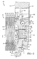
- housing 11 provides a cavity 24 which is formed radially interior of stationary surface 18. Cavity 24 projects into end wall 12 and may be generally cylindrical, centered about axis 22. A boss 25 is disposed at least partially within cavity 24 and projects axially from end wall 12. Boss 25 is centered on axis 22 and may be tapered. As is evident from Fig. 2, boss 25 terminates at a top surface 26 which is relatively further from end wall 12 than stationary surface 18. Boss 25 is provided with a threaded hole 27 which is aligned with axis 22 and extends from top surface 26 axially into boss 25. Threaded hole 27 is adapted to receive a screw 28 which includes a threaded portion 29 and a head 30. A boss washer 31 is secured between the head 30 and top surface 26 when the screw 28 is received in threaded hole 27.
- springs 50 are achieved through a simplified method. Rotatable actuator 40 and balls 23 are placed within chamber 17 in the previously described orientation. Spring 50 is then positioned within bore 46. Retaining washer 51 and boss washer 31 are positioned on the end of spring 50 opposed to flange 48. Screw 28 is then inserted into threaded hole 27. Prior to rotation of screw 28, ;no tension is realized on spring 50. As screw 28 is tightened, thus moving boss washer 31 and retaining washer 51 axially toward end wall 12, spring 50 is compressed. Spring 50 may be sized such that once screw 28 is fully tightened, thereby securing boss washer 31 between head 30 and top surface 26, the optimal compression is achieved.
Abstract
Description
- This invention relates to a ball ramp brake with rotatable actuator. More specifically, this invention relates to such a brake wherein the rotatable actuator is biased toward a non-actuated state by a center mounted spring.
- Ball ramp caliper brakes are a useful and convenient means of providing a braking force. Generally such brakes include a rotatable actuator and a stationary actuator, each of which have depressions which are circumferentially spaced around an axis. Steel balls are held within these depressions, and when the rotatable actuator is caused to rotate, the balls roll gradually along the depressions. This in turn causes the rotatable actuator to move axially away from the stationary actuator thereby applying a braking force to a disc assembly. These brakes are relatively simple in design because they do not require complex hydraulic mechanisms. Thus, the brakes are relatively dependable and easy to service and operate. Still some deficiencies exist in prior art ball ramp brakes.
- One such deficiency is the undue complexity and inadequacies in the return mechanism. Such return mechanisms are provided to return the brake to an unactuated state after the rotatable actuator is rotated. Prior art return mechanisms typically include a plurality of springs which are coupled to the rotatable actuator and pre-tensioned to pull the rotatable actuator toward the stationary actuator. These springs are circumferentially spaced around the axis of rotation and resist the outward axial movement of the rotatable actuator. This orientation is unduly complex primarily due to difficulties in the construction and pre-tensioning of the springs. Further, because a plurality of outwardly spaced springs are used, the return force may be uneven resulting in undue wear and reduced performance. Still further, such designs typically require an additional spring positioned on the actuating cable which rotates the rotatable actuator. Thus, multiple springs are required to provide adequate return forces. This added complexity can cause increased cost, difficulty in construction and added maintenance concerns.
- Yet another deficiency in prior art ball ramp brakes is found at the interface of the rotatable actuator and disc assembly. Typically, the disc assembly includes a plurality of rotatable discs which are slidably coupled to a rotatable shaft and a plurality of stationary discs located at the ends of the disc assembly and interposed between the rotatable discs. The stationary discs fit over, but do not engage, the rotating shaft, and are slidably coupled to the housing via a plurality of pins. Thus, the rotatable discs rotate with the shaft and the stationary discs are prevented from rotating relative to the housing. The entire disc assembly is free to slide axially so that when an axial force is applied to the disc assembly via the rotatable actuator, the discs are clamped together and the rotatable discs urge the stationary discs to rotate. Because the stationary discs are coupled to the housing, they are prevented from relative rotation, and a braking torque is applied to the rotating shaft. Yet because of the relative tolerances and the nature of the engagement between the stationary discs and the pins, a certain amount of clearance is necessary between the pin and stationary discs, and this clearance allows for a small degree of rotation. Thus, when the rotatable and stationary discs are caused to engage each other, the stationary discs will rotate slightly, until they fully engage the pin, which restricts any further rotation. Additionally, because the stationary discs are typically metallic, some degree of Aflex@ occurs when a rotational torque is applied by the rotatable discs. The result of these combined effects is that the stationary disc which engages the rotatable actuator will apply a slight feedback rotation to the rotatable actuator as the disc assembly is axially compressed- This feedback rotation can greatly affect the resulting braking torque depending upon the direction of shaft rotation. For example, if the shaft rotates in the same direction as the rotatable actuator, the feedback rotation will supplement the rotation of the rotatable actuator, resulting in a greater net braking torque. If the shaft rotates in the opposite direction as the rotatable actuator, the feedback rotation will oppose the rotation of the rotatable actuator, resulting in a reduced net braking torque. This variation in braking force, referred to as a directional bias, is undesirable in many applications.
- Further, prior art brakes of this design are inefficient because, as the rotatable actuator is rotated, friction is created between the rotatable actuator and the stationary disc proximate thereto. Thus, much of the force applied by the rotatable actuator is absorbed due to the friction, causing a loss in braking efficiency.
- In view of these problems, it is evident that the need exists for a ball ramp brake which provides a return mechanism with a reduced number of axially aligned springs and which eliminates the brake torque directional bias.
- It is thus an object of the present invention to provide a ball ramp brake which incorporates a central spring.
- It is a further object of the present invention to provide a brake, as above, which applies an axially aligned return force.
- It is an additional object of the present invention to provide a brake, as above, which is efficient.
- It is another object of the present invention to provide a brake, as above, which eliminates brake torque directional bias.
- These and other objects of the present invention, as well as the advantages thereof over existing prior art forms, which will become apparent from the description to follow, are accomplished by the improvements hereinafter described and claimed.
- In general, a brake in accordance with the present invention is adapted to be rotationally coupled with an output shaft. The brake includes a housing having a first surface. The first surface includes a plurality of depressions which are circumferentially spaced about an axis. A rotatable actuator includes a second surface which has a plurality of depressions which are circumferentially spaced about the axis. The first and second surface depressions are adjacent to and face each other, and are adapted to carry one of a plurality of balls therebetween. At least one biasing means is centered about the axis and adapted to bias the rotatable actuator toward the housing. When the rotatable actuator is caused to rotate, it correspondingly moves axially away from the housing, causing a braking force to be applied to the output shaft.
- In accordance with another aspect of the present invention, a brake which is adapted to be rotationally coupled with an output shaft includes a housing which defines a chamber. The housing includes a boss which projects into the chamber and is centered on an axis. A rotatable actuator is received in the chamber and is rotatable about the axis. The rotatable actuator includes a body portion and a central circumferential flange which extends radially inward relative to the body portion: The central circumferential flange defines a central aperture. A spring is included. A means is positioned proximate to the axial end of the boss to retain the spring against the circumferential flange. The boss is received through the aperture and a spring is carried by the boss and axially confined between the circumferential flange and the retaining means. When the rotatable actuator is rotated, a braking force is applied to the output shaft.
- In accordance with yet another aspect of the present invention, a brake for applying a braking force to an external shaft includes a housing which defines a chamber. The housing includes a plurality of depressions which are circumferentially spaced around an axis. A rotatable actuator is received in the chamber and includes a plurality of depressions circumferentially spaced around the axis. The housing depressions face the rotatable actuator depressions and each matching pair of depressions receive a ball therebetween. A spring under compression is positioned centrally about the axis. When the rotatable actuator is rotated, the balls roll along the depressions which moves the rotatable actuator axially away from the housing to apply a braking force to the shaft. The spring compressively opposes the axial movement of the rotatable actuator away from the housing.
- In accordance with still another aspect of the present invention, a brake for applying a braking force to a shaft includes a housing having a plurality of depressions which are circumferentially spaced around an axis. A rotatable actuator is positioned proximate to the housing and includes a plurality of depressions circumferentially spaced around the axis. The housing depressions face the rotatable actuator depressions. A ball is received between each matching pair of depressions. A disc assembly includes a plurality of stationary discs operatively coupled to the housing and a plurality of rotatable discs carried by the shaft. The rotatable discs are positioned to be engaged by the stationary discs, and an annular roller bearing is positioned between the disc assembly and the rotatable actuator. When the rotatable actuator is rotated, the balls roll along the depressions to gradually shallower portions thereof to move the rotatable actuator axially away from the housing.
- In accordance with still another aspect of the present invention, a brake for applying a braking force to a shaft including a housing having a plurality of depressions which are circumferentially spaced around an axis. A rotatable actuator is positioned proximate to the housing, and includes a plurality of depressions circumferentially spaced around the axis. The housing depressions face the rotatable actuator depressions. A ball is received between each matching pair of depressions. A disc assembly includes a plurality of stationary discs operatively coupled to the housing and a plurality of rotatable discs carried by the shaft. The rotatable discs are positioned to be engaged by the stationary discs. A bearing positioned between the disc assembly and the rotatable actuator, and a spring under compression is positioned centrally about the axis. When the rotatable actuator is rotated, the balls roll along the depressions to move the rotatable actuator axially away from the housing, thereby applying a braking force to the shaft. The spring opposes the axial movement of the rotatable actuator away from the housing.
- A preferred exemplary ball ramp brake according to the concepts of the present invention is shown by way of example in the accompanying drawings without attempting to show all the various forms and modifications in which the invention might be embodied, the invention being measured by the appended claims and not by the details of the specification.
-
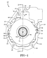
- Fig. 1 is a elevational view showing a brake assembly made in accordance with the present invention.
- Fig. 2 is a sectional view taken substantially along line 2-2 of Fig. 1.
- Fig. 3 is an elevational view of the inside of a housing of the brake of Fig. 1.
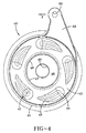
- Fig. 4 is an elevational view of the rotatable actuator of the brake of Fig. 1.
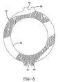
- Fig. 5 is an elevational view of the primary disc of the brake of Fig. 1.
- A brake made in accordance with the present invention is indicated generally by the numeral 10 and includes a
housing 11 which contains and protects the working brake components in addition to providing means to mountbrake 10 to a piece of equipment or vehicle.Housing 11 is generally cup-shaped in section having aback wall 12 which generally defines the base ofhousing 11, and aside wall 13 extending from the outer periphery ofback wall 12.Side wall 13 terminates at a mountingsurface 14 which may be generally planar to facilitate mounting flush to a vehicle or device frame (not shown). Further to that end, a plurality ofbores 15 may be provided which extend through bothback wall 12 andsidewall 13.Bores 15 may receive securing means therethrough which are captured by the vehicle body to securebrake 10 thereto. For example, a plurality of bolts (not shown) may be provided which are received throughbores 15 and secured to a vehicle or machine frame. Acover plate 16 is secured to backwall 12 by a plurality ofbolts 32.Cover plate 16 may be removed to provide access to brake components, such as cables, during installation or servicing. - As is evident from Figs. 2 and 3,
back wall 12 andside wall 13 define achamber 17, in which some of the working brake components reside.Chamber 17 is provided with a stationary actuator surface 18 (hereinafter stationary surface 18) which extends axially outwardly fromback wall 12 intochamber 17. As is evident from Fig. 3,stationary surface 18 is provided with a plurality ofdepressions 19. In the present embodiment, fivedepressions 19 are shown and are disposed in a spaced circumferential pattern about anaxis 22. Eachdepression 19 includes ahead portion 20 and atapered tail portion 21 projecting circumferentially therefrom.Depressions 19 are deepest at thehead portion 20 and become relatively more shallow alongtail portion 21. Though five depressions are shown in Fig. 3, it should be appreciated that more or less may be employed. Eachdepression 19 is adapted to receive aball 23 therein. It is preferred thatdepressions 19 provide a gradual reduction in depth fromhead portion 20 totail portion 21. This reduction in depth also corresponds to the direction of travel ofball 23, as will be hereinafter described. - As is evident from Fig. 2,
housing 11 provides acavity 24 which is formed radially interior ofstationary surface 18.Cavity 24 projects intoend wall 12 and may be generally cylindrical, centered aboutaxis 22. Aboss 25 is disposed at least partially withincavity 24 and projects axially fromend wall 12.Boss 25 is centered onaxis 22 and may be tapered. As is evident from Fig. 2,boss 25 terminates at atop surface 26 which is relatively further fromend wall 12 thanstationary surface 18.Boss 25 is provided with a threadedhole 27 which is aligned withaxis 22 and extends fromtop surface 26 axially intoboss 25. Threadedhole 27 is adapted to receive ascrew 28 which includes a threadedportion 29 and ahead 30. Aboss washer 31 is secured between thehead 30 andtop surface 26 when thescrew 28 is received in threadedhole 27. -
Chamber 17 receives arotatable actuator 40 therein. As will become evident,actuator 40 is rotatable aboutaxis 22 and, upon such rotation, engagesbrake 10.Rotatable actuator 40 includes a generallyannular body portion 41 centered aroundaxis 22.Body portion 41 provides a rotatable actuator surface 42 (hereinafter rotatable surface 42) which is adjacent to and facesstationary surface 18.Rotatable surface 42 is generally disc-shaped and is provided with a plurality ofdepressions 43. As is best shown in Fig. 4,depressions 43 ofrotatable actuator 40 are oriented to align withdepressions 19 onhousing 11. Thus, in the present embodiment, fivedepressions 43 are included, each having ahead portion 44 and atapered tail portion 45 projecting circumferentially therefrom. Thedepressions 43 are deepest at the head portion and become relatively more shallow alongtail portion 44. Further,depressions 43 are spaced circumferentially the same distance fromaxis 22 asdepressions 19. As shown in Fig. 2, eachdepression 43 is adapted to receive aball 23 therein. In such a manner, eachball 23 is secured between adjacent or facingdepressions tail portion 21 ofdepression 19 faces in the opposed circumferential direction fromtail portion 45 ofdepressions 43. Thus, as will become apparent, whenrotatable actuator 40 is rotated aboutaxis 22,balls 23 roll along thedepressions head portions tail portions rotatable actuator 40 axially away fromend wall 12. -
Rotatable actuator 40 is provided with acentral bore 46 which is defined bybody portion 41 and anaxially extending lip 47 which projects axially towardend wall 12 intocavity 24.Lip 47 terminates at acircumferential flange 48 which projects radially inward and defines anaperture 49.Aperture 49 is sized to allowboss 25 to extend therethrough. Positioned betweenflange 48 andboss washer 31 is aspring 50. While asingle spring 50 is shown, it should be appreciated that a plurality of springs may be employed. For example, a pair of springs may be provided with one having a diameter greater than the other. The springs could then be concentrically positioned betweenflange 48 andboss washer 31. - A retaining
washer 51 is positioned betweensprings 50 andboss washer 31. The inner diameter of retainingwasher 51 is sized to allow theboss 25 to fit therein. The outer diameter of retainingwasher 51 is sized to allow sufficient surface area forspring 50 to contact. Thus,spring 50 is positioned aroundboss 25 and axially confined betweenflange 48 and retainingwasher 51. As shown in Fig. 2,spring 50 is under compression when assembled and thus biases rotatableactuator 40 towardsend plate 12. This occurs becausespring 50 presses against both retainingwasher 51 andflange 48. Because retainingwasher 51 is prevented from axial movement away fromend wall 12 byboss washer 31, a compressive force presses againstflange 48 ofrotatable actuator 40 and urgesrotatable actuator 40 towardsend wall 12. - It should be appreciated that the assembly and compression of
springs 50 is achieved through a simplified method.Rotatable actuator 40 andballs 23 are placed withinchamber 17 in the previously described orientation.Spring 50 is then positioned withinbore 46. Retainingwasher 51 andboss washer 31 are positioned on the end ofspring 50 opposed toflange 48.Screw 28 is then inserted into threadedhole 27. Prior to rotation ofscrew 28, ;no tension is realized onspring 50. Asscrew 28 is tightened, thus movingboss washer 31 and retainingwasher 51 axially towardend wall 12,spring 50 is compressed.Spring 50 may be sized such that oncescrew 28 is fully tightened, thereby securingboss washer 31 betweenhead 30 andtop surface 26, the optimal compression is achieved. -
Rotatable actuator 40 further includes a bearingsurface 55 which faces away fromend wall 12. Bearingsurface 55 is adapted to contact aroller bearing assembly 56.Roller bearing assembly 56 is annular and includes aframe 57 which carries a plurality of radially orientedcylindrical bearings 58. Alip 59 is provided on the inner radial edge of bearingsurface 55 which radially locatesroller bearing assembly 56 onrotatable actuator 40.Rotatable actuator 40 is further provided with anactuator arm 60 which projects radially frombody 41.Actuator arm 60 is provided with aneyelet 61 which is adapted to facilitate connection to an actuator cable (not shown). -
Brake 10 includes a disc assembly generally indicated by the numeral 70, which includes a plurality ofrotatable discs 71 and a plurality ofstationary discs 72.Rotatable discs 71 andstationary discs 72 are stacked in an alternating manner as seen in Fig. 2. In the present embodiment five rotatable and five stationary discs are shown, but it should be appreciated that any number may be-used.Rotatable discs 71 are provided with a radiallyinner surface 74 which is splined to engage the matching splines of a drive shaft (not shown). In this manner, as the drive shaft rotates,rotatable discs 71 rotate therewith.Rotatable discs 71 are rotationally coupled to the shaft but are free to slide axially thereon. The drive shaft may be operatively coupled to any working mechanism. For example, the drive shaft may be operatively coupled to the axle of a vehicle. Thus, when a braking torque is applied to the drive shaft, it is consequently applied to the axle, thus slowing the vehicle or other device. -
Stationary discs 72 have a radiallyinner surface 76 which fits over, but is not engage by, the splined drive shaft. As best shown in Fig. 1,stationary discs 72 are provided with diametricallyopposed ears 77 which extend radially outwardly therefrom. In the embodiment disclosed, one pair of ears is provided, but it should be appreciated that any number of pairs may be employed. Eachear 77 is provided with agroove 78 which is adapted to slidingly receive apin 79 therein.Pins 79 are each securedly received in one of a plurality ofholes 80 located inside wall 13 ofhousing 11. The opposed end of eachpin 79 is received in a corresponding hole (not shown) in a vehicle or machine frame. In this manner, the pins are secured between the frame andhousing 11. Likewise,stationary discs 72 are coupled to the housing viapins 79, and thus prevented from rotating.Stationary discs 72 are, however, free to slide axially along pins 79. When mounted to a vehicle or device, a surface (not shown) is provided which is proximate to the outermost stationary disc which prevents outward axial movement of the disc assembly. Therefore, when an axial force is applied to one end ofdisc assembly 70, the discs are caused to slide axially and in turn the discs are caused to engage each other. When the discs engage each other a braking torque is applied to the drive shaft due to the friction created betweenrotatable discs 71 andstationary discs 72 which are prevented from rotating by pins 79. -
Disc assembly 70 further includes aprimary disc 81 positioned on the end ofdisc assembly 70 proximate to therotatable actuator 40.Primary disc 81 is annular, with aninner surface 82 which may fit over but does not engage the drive shaft. As is evident from Fig. 2, the inside diameter ofprimary disc 81 is relatively larger than that ofstationary discs 72. This orientation allows clearance forlip 59 so that no frictional contact occurs betweenrotatable actuator 40 andprimary disc 81. As seen in Fig. 5,primary disc 81 is provided with a pair of diametricallyopposed ears 83 which extend radially outward therefrom. In present embodiment, one pair of ears is provided, but it should be appreciated that any number of pairs may be provided.Ears 83 are adapted to slidingly engage pins 79. To that end, each ear is provided with agroove 84, each of which slidingly receives apin 79 therein. In this manner,primary disc 81 is coupled to the housing, and thus prevented from rotating. Theprimary disc 81 is, however, free to slide axially along pins 79. As is evident from Fig. 2, bearing 56 is interposed betweenprimary disc 81 androtatable actuator 40. Thus, the bearing 56 transfers axial forces betweenrotatable actuator 40 andprimary disc 81 yet, becauserollers 58 roll along bearingsurface 55 and along the surface ofprimary disc 81, no rotational torque is transferred betweendisc assembly 70 androtatable actuator 40. - An unactuated state is achieved when no external forces are applied to brake 10. In such a case,
spring 50 biases rotatableactuator 40 axially towardend wall 12. Because no other forces are present,rotatable actuator 40 will orient itself such thatballs 23 reside inhead portions respective depressions balls 23 reside in the deepest portions of the depressions and thereforerotatable actuator 40 is positioned at the shortest relative distance fromend wall 12 so thatrotatable discs 71 can rotate freely betweenstationary discs 72. -
Brake 10 may be selectively actuated, thereby applying a braking force to the shaft. Actuation is accomplished by applying a generally tangential force F onactuator arm 60, which may be provided by an actuator cable (not shown) which extends through a bore 85 (Fig. 3) in thehousing 11. By pulling onactuator arm 60 therotatable actuator 40 is caused to rotate aroundaxis 22 which in turn causesdepressions 43 ofrotatable actuator 40 to move relative todepressions 19 ofhousing 11. As such, eachball 23 rolls alongtail portions rotatable actuator 40 axially away fromend wall 12 ofhousing 11. This axial force is then transferred to thedisc assembly 70 via theroller bearing 56. Becauserollers 58 are free to rotate, only axial, and no rotational force is transmitted. Thus, almost no rotational frictional forces are transferred to theprimary disc 81. The axial force is thus applied toprimary disc 81 and consequently theentire disc assembly 70 slides axially. Becausedisc assembly 70 is prevented from outward axial movement by a surface on the vehicle, the discs are caused to engage each other. When the discs engage each other, a braking torque is applied to the drive shaft due to the friction created betweenrotatable discs 71 andstationary discs 72 which are prevented from rotating by pins 79. - When the force F is released,
spring 50, by pressing againstflange 48, forces rotatable actuator 40 axially towardend wall 12. In doing so,rotatable actuator 40 will rotate and return to its unactuated state. The unactuated state is achieved whenballs 23 again rest in the deepest portions ofdepressions - The presence of
roller bearing 56, provides further advantages to brake 10. Specifically, because thebearing 56 is interposed between therotatable actuator 40 and theprimary disc 81, no feedback rotation is transferred to therotatable actuator 40. In other words, as thedisc assembly 70 compresses, the feedback rotation fromprimary disc 81 causes bearing 56 to rotate, and because bearing 56 rolls across bearingsurface 55, the torque is not transferred to therotatable actuator 40. Thus, no directional bias is realized and consequently the same braking force is applied regardless of the direction of rotation of the shaft. - It should also be appreciated that
boss washer 31 and retainingwasher 51 act as a bearing surface. Specifically, asrotatable actuator 40 rotates,spring 50 and retainingwasher 51 rotate with it.Boss washer 31 is rotationally fixed byscrew 28. This orientation generates relatively low frictional forces and thus does not hamper efficiency of the brake. - Thus the above described
brake 10 represents an improvement over prior art brakes. Specifically, by positioningspring 50 centered onaxis 22, very high actuator return forces can be realized. Indeed,central spring 50 provides the forces needed not only to return therotatable actuator 40 to the unactuated position, but to return a brake actuation cable as well. Further, compression ofspring 50 is simplified. Specifically, tension is applied by simply running downscrew 28 intohole 27. This alleviates the need to pre-tension springs using complicated assembly procedures. Still further, by providing thespring 50 centered onaxis 22, a centered and axially balanced return force is applied torotatable actuator 40, thereby eliminating imbalances which could lead to shortened brake life. Further, because thebearing 56 is interposed between therotatable actuator 40 and theprimary disc 81, no rotational torque is transferred therebetween and thus no directional bias is realized. Therefore, the the same braking force is applied regardless of the direction of rotation of the shaft. - In view of the foregoing, it should thus be evident that a brake as described herein accomplishes the objects of the present invention and otherwise substantially improves the art.
- Further embodiments of the present invention are described with reference to the following paragraphs:
- 1.
- A brake adapted to be rotationally coupled with an output shaft, the brake comprising a housing which includes a first surface, said first surface having a plurality of depressions which are circumferentially spaced about an axis, a rotatable actuator having a second surface, said second surface having a plurality of depressions which are circumferentially spaced about said axis, said first surface depression and said second surface depression being adjacent to and facing each other, and a ball positioned between each said first depression and each said second depression, and biasing means centered about said axis and adapted to bias said rotatable actuator toward said housing, such that when said rotatable actuators rotates, said rotatable actuator moves axially away from said housing, causing a braking force to be applied to the output shaft.
- 2.
- A brake according to paragraph 1 wherein said biasing means includes a spring.
- 3.
- A brake according to paragraph 1 or paragraph 2 wherein said housing includes a boss which is centered on said axis, said boss receiving said bias means thereon.
- 4.
- A brake according to paragraph 3 wherein said rotatable actuator includes an annular body and a central cavity, said central cavity includes a bottom surface defined by a circumferential flange, said circumferential flange projecting radially inward and defining an aperture.
- 5.
- A brake according to paragraph 4 wherein said brake includes a retaining washer positioned proximate to the axial end of said boss, said boss projecting through said aperture, said biasing means being axially confined by said retaining washer and said flange.
- 6.
- A brake according to paragraph 5, wherein said boss includes a threaded hole centered on said axis and positioned on the axial end of said boss, and further comprising a screw received in said hole, and a boss washer captured by said screw and having a diameter greater than said boss.
- 7.
- A brake according to paragraph 6, wherein said retaining washer is slidably received on said boss and prevented from axial movement beyond the axial end of said boss by said boss washer.
- 8.
- A brake according to any of paragraphs 1 to 7 further comprising a disc assembly including a plurality of stationary discs carried by said housing and a plurality of rotatable discs carried the output shaft, said rotatable discs being positioned to be engaged by said stationary discs.
- 9.
- A brake according to paragraph 8 further comprising a bearing interposed between said rotatable actuator and said disc assembly.
- 10.
- A brake according to paragraph 9 wherein said bearing is an annular roller bearing.
- 11.
- A brake according to any of paragraphs 1 to 10 wherein when said rotatable actuator includes a radially extending arm, said rotatable actuator being caused to rotate when a substantially tangential force is applied to said arm.
- 12.
- A brake adapted to be rotationally coupled with an output shaft, the brake comprising a housing which defines a chamber, said housing having a boss projecting into said chamber and centered on an axis, a rotatable actuator received in said chamber and rotatable about said axis, said rotatable actuator including a body portion and a central circumferential flange which extends radially inward relative to said body portion, said central circumferential flange defining a central aperture, a spring, and a means positioned proximate to the axial end of said boss to retain said spring against said circumferential flange, said boss being received through said aperture, said spring being carried by said boss and axially confined between said circumferential flange and said retaining means, wherein when said rotatable actuator is rotated, a braking force is applied to the output shaft.
- 13.
- A brake according to
paragraph 12 wherein said rotatable actuator includes a plurality of depressions circumferentially spaced around said axis, and said housing includes a plurality of depressions which are circumferentially spaced around said axis, said housing depressions facing said rotatable actuator depressions, and a ball received between said housing depressions and said rotatable actuator depressions. - 14.
- A brake according to
paragraph 13 wherein rotation of said rotatable actuator causes said balls to roll along said depressions to gradually shallower portions thereof, thereby moving said rotatable actuator axially away from said housing. - 15.
- A brake according to
paragraph 14 wherein said spring opposes said axial movement of said rotatable actuator away from said housing. - 16.
- A brake according to any of
paragraphs 12 to 15 further comprising a disc assembly including a plurality of stationary discs carried by said housing and a plurality of rotatable discs carried by the output shaft, said rotatable discs being positioned to be engaged by said stationary discs. - 17.
- A brake according to
paragraph 16, wherein when said rotatable actuator rotates, an axial force is applied to said disc assembly, thereby causing frictional contact between said rotatable discs and said stationary discs. - 18.
- A brake according to any of
paragraphs 12 to 17, wherein said boss includes a threaded hole on said axis and positioned on the axial end of said boss, and further comprising a screw received in said hole, and a boss washer captured between said screw and said boss, said boss washer has a greater diameter than said boss. - 19.
- A brake according to
paragraph 18, wherein said retaining washer is slidably received on said boss and prevented from axial movement beyond the axial end of said boss by said boss washer. - 20.
- A brake according to any of
paragraphs 12 to 19 further comprising a bearing interposed between said rotatable actuator and said disc assembly. - 21.
- A brake according to
paragraph 20 wherein said bearing is an annular roller bearing. - 22.
- A brake for applying a braking force to a shaft comprising a housing defining a chamber, said housing including a plurality of depressions which are circumferentially spaced around an axis, a rotatable actuator positioned in said chamber, said rotatable actuator including a plurality of depressions circumferentially spaced around said axis, said housing depressions facing said rotatable actuator depressions, a ball received between each matching pair of depressions, a spring under compression and positioned centrally about said axis, wherein when said rotatable actuator is rotated, said balls roll along said depressions to move said rotatable actuator axially away from said housing, thereby applying a braking force to said shaft, said spring compressively opposing said axial movement of said rotatable actuator away from said housing.
- 23.
- A brake for applying a braking force to a shaft comprising a housing including a plurality of depressions which are circumferentially spaced around an axis, a rotatable actuator positioned proximate to said housing, said rotatable actuator including a plurality of depressions circumferentially spaced around said axis, said housing depressions facing said rotatable actuator depressions, a ball received between each matching pair of depressions, a disc assembly including a plurality of stationary discs operatively coupled to said housing and a plurality of rotatable discs carried by the shaft, said rotatable discs being positioned to be engaged by said stationary discs, and an annular roller bearing positioned between said disc assembly and said rotatable actuator, wherein when said rotatable actuator is rotated, said balls roll along said depressions to move said rotatable actuator axially away from said housing.
- 24.
- A brake according to
paragraph 23 further comprising a spring under compression positioned centrally about said axis and adapted to oppose the axial movement of said rotatable actuator away from said housing. - 25.
- A brake according to
paragraph 24 wherein said housing includes a boss which is centered on said axis, said boss receiving said spring thereon. - 26.
- A brake according to
paragraph 25 wherein said rotatable actuator includes an annular body and a central cavity, said central cavity includes a bottom surface defined by a circumferential flange, said circumferential flange projecting radially inward and defining an aperture. - 27.
- A brake according to
paragraph 26 wherein said brake includes a retaining washer positioned proximate to the axial end of said boss, said boss projecting through said aperture, said spring being axially confined by said retaining washer and said flange. - 28.
- A brake for applying a braking force to a shaft comprising a housing including a plurality of depressions which are circumferentially spaced around an axis, a rotatable actuator positioned proximate to said housing, said rotatable actuator including a plurality of depressions circumferentially spaced around said axis, said housing depressions facing said rotatable actuator depressions, a ball received between each facing pair of depressions, a disc assembly including a plurality of stationary discs operatively coupled to said housing and a plurality of rotatable discs carried by the shaft, said rotatable discs being positioned to be engaged by said stationary discs, a bearing positioned between said disc assembly and said rotatable actuator, and a spring under compression positioned centrally about said axis, wherein when said rotatable actuator is rotated, said balls roll along said depressions to move said rotatable actuator axially away from said housing, thereby applying a braking force to said shaft, said spring opposing said axial movement of said rotatable actuator away from said housing.
- In view of the foregoing, it should thus be evident that a brake as described herein accomplishes the objects of the present invention and otherwise substantially improves the art.
Claims (14)
- A brake (10) adapted to be rotationally coupled with an output shaft, the brake comprising a housing (11) which includes a first surface (18), said first surface (18) having a plurality of depressions (19) which are circumferentially spaced about an axis (22), a rotatable actuator (40) having a second surface (42), said second surface (42) having a plurality of depressions (43) which are circumferentially spaced about said axis (22), said first surface depression (19) and said second surface depression (43) being adjacent to and facing each other, and a ball (23) positioned between each said first depression (19) and each said second depression (43), and biasing means centered about said axis (22) and adapted to bias said rotatable actuator (40) toward said housing (11), such that when said rotatable actuators (40) rotates, said rotatable actuator (40) moves axially away from said housing (11), causing a braking force to be applied to the output shaft.
- A brake according to claim 1 wherein said housing (11) includes a boss (25) which is centered on said axis (22), said boss (25) receiving said bias means thereon.
- A brake according to claim 2 wherein said rotatable actuator (40) includes an annular body (41) and a central cavity (46), said central cavity (46) includes a bottom surface defined by a circumferential flange (48), said circumferential flange (48) projecting radially inward and defining an aperture.
- A brake according to claim 3 wherein said brake (10) includes a retaining washer (51) positioned proximate to the axial end of said boss (25), said boss (25) projecting through said aperture, said biasing means being axially confined by said retaining washer (51) and said flange (48).
- A brake according to claim 4, wherein said boss (25) includes a threaded hole (27) centered on said axis (22) and positioned on the axial end of said boss (25), and further comprising a screw (28) received in said hole (27), and a boss washer (31) captured by said screw (28) and having a diameter greater than said boss (25).
- A brake according to claim 5, wherein said retaining washer (51) is slidably received on said boss (25) and prevented from axial movement beyond the axial end of said boss (25) by said boss washer (31).
- A brake according to any preceding claim further comprising a disc assembly (70) including a plurality of stationary discs (72) carried by said housing (11) and a plurality of rotatable discs (71) carried by the output shaft, said rotatable discs (71) being positioned to be engaged by said stationary discs (72).
- A brake according to claim 7 further comprising a bearing interposed between said rotatable actuator (40) and said disc assembly (70).
- A brake according to claim 8 wherein said bearing is an annular roller bearing (56).
- A brake according to any preceding claim wherein when said rotatable actuator (40) includes a radially extending arm (60), said rotatable actuator (40) being caused to rotate when a substantially tangential force is applied to said arm (60).
- A brake adapted to be rotationally coupled with an output shaft, the brake comprising a housing (11) which defines a chamber (17), said housing (11) having a boss (25) projecting into said chamber (17) and centered on an axis (22), a rotatable actuator (40) received in said chamber (17) and rotatable about said axis (22), said rotatable actuator (40) including a body portion (41) and a central circumferential flange (48) which extends radially inward relative to said body portion (41), said central circumferential flange (48) defining a central aperture (46), a spring (50), and a means positioned proximate to the axial end of said boss (25) to retain said spring (50) against said circumferential flange (48), said boss (25) being received through said aperture, said spring (50) being carried by said boss (25) and axially confined between said circumferential flange (48) and said retaining means, wherein when said rotatable actuator (40) is rotated, a braking force is applied to the output shaft.
- A brake for applying a braking force to a shaft comprising a housing (11) defining a chamber (17), said housing (11) including a plurality of depressions (19) which are circumferentially spaced around an axis (22), a rotatable actuator (40) positioned in said chamber (17), said rotatable actuator (40) including a plurality of depressions (43) circumferentially spaced around said axis (22), said housing depressions (19) facing said rotatable actuator depressions (43), a ball (23) received between each matching pair of depressions (19 and 43), a spring (50) under compression and positioned centrally about said axis (22), wherein when said rotatable actuator (40) is rotated, said balls (23) roll along said depressions (19 and 43) to move said rotatable actuator (40) axially away from said housing (11), thereby applying a braking force to said shaft, said spring (50) compressively opposing said axial movement of said rotatable actuator (40) away from said housing (11).
- A brake for applying a braking force to a shaft comprising a housing (11) including a plurality of depressions (19) which are circumferentially spaced around an axis (22), a rotatable actuator (40) positioned proximate to said housing (11), said rotatable actuator (40) including a plurality of depressions (43) circumferentially spaced around said axis (22), said housing depressions (19) facing said rotatable actuator depressions (43), a ball (23) received between each matching pair of depressions (19 and 43), a disc assembly (70) including a plurality of stationary discs (72) operatively coupled to said housing (11) and a plurality of rotatable discs (71) carried by the shaft, said rotatable discs (71) being positioned to be engaged by said stationary discs (72), and an annular roller bearing (56) positioned between said disc assembly (70) and said rotatable actuator (40), wherein when said rotatable actuator (40) is rotated, said balls (23) roll along said depressions (19 and 43) to move said rotatable actuator (40) axially away from said housing (11).
- A brake for applying a braking force to a shaft comprising a housing (11) including a plurality of depressions (19) which are circumferentially spaced around an axis (22), a rotatable actuator (40) positioned proximate to said housing (11), said rotatable actuator (40) including a plurality of depressions (43) circumferentially spaced around said axis (22), said housing depressions (19) facing said rotatable actuator depressions (43), a ball (23) received between each facing pair of depressions (19 and 43), a disc assembly (70) including a plurality of stationary discs (72) operatively coupled to said housing (11) and a plurality of rotatable discs (71) carried by the shaft, said rotatable discs (71) being positioned to be engaged by said stationary discs (72), a bearing (56) positioned between said disc assembly (70) and said rotatable actuator (40), and a spring (50) under compression positioned centrally about said axis (22), wherein when said rotatable actuator (40) is rotated, said balls (23) roll along said depressions (19 and 43) to move said rotatable actuator (40) axially away from said housing (11), thereby applying a braking force to said shaft, said spring (50) opposing said axial movement of said rotatable actuator (40) away from said housing (11).
Applications Claiming Priority (1)
| Application Number | Priority Date | Filing Date | Title |
|---|---|---|---|
| US11/314,449 US7735612B2 (en) | 2005-12-22 | 2005-12-22 | Ball ramp brake |
Publications (3)
| Publication Number | Publication Date |
|---|---|
| EP1801449A2 true EP1801449A2 (en) | 2007-06-27 |
| EP1801449A3 EP1801449A3 (en) | 2008-08-27 |
| EP1801449B1 EP1801449B1 (en) | 2012-08-01 |
Family
ID=37875717
Family Applications (1)
| Application Number | Title | Priority Date | Filing Date |
|---|---|---|---|
| EP06026559A Active EP1801449B1 (en) | 2005-12-22 | 2006-12-21 | Ball ramp brake |
Country Status (2)
| Country | Link |
|---|---|
| US (1) | US7735612B2 (en) |
| EP (1) | EP1801449B1 (en) |
Families Citing this family (7)
| Publication number | Priority date | Publication date | Assignee | Title |
|---|---|---|---|---|
| US8235183B2 (en) * | 2008-02-25 | 2012-08-07 | Ausco Products, Inc. | Ball ramp brake |
| JP5532246B2 (en) * | 2010-09-30 | 2014-06-25 | 日立オートモティブシステムズ株式会社 | Thrust generator, disc brake and stabilizer |
| EP2570379B1 (en) * | 2011-09-15 | 2015-11-11 | EPSILON Kran GmbH. | Swivel joint assembly |
| US9163680B2 (en) * | 2012-09-18 | 2015-10-20 | Foster-Miller, Inc. | Powerless brake |
| TWM525318U (en) * | 2015-07-24 | 2016-07-11 | Hsin-Fa Wang | Disk brake |
| US9630086B1 (en) | 2015-12-08 | 2017-04-25 | John M. Wahe | Leveling device, system and method |
| US11846332B2 (en) | 2022-03-01 | 2023-12-19 | Ausco Products, Inc. | Open-ended, spring applied, hydraulically released brake with full alignment of components |
Citations (1)
| Publication number | Priority date | Publication date | Assignee | Title |
|---|---|---|---|---|
| EP1039165A2 (en) | 1999-03-23 | 2000-09-27 | Eaton Corporation | Ball ramp inertia brake with oil blocking ring |
Family Cites Families (10)
| Publication number | Priority date | Publication date | Assignee | Title |
|---|---|---|---|---|
| SE7414359L (en) * | 1974-11-15 | 1976-05-17 | Bofors Ab | WAY TO COOL A WATER SLAM COUPLING AND THE SPECIAL COUPLING SLAM |
| US4372433A (en) * | 1980-04-14 | 1983-02-08 | Briggs & Stratton Corporation | Combination clutch/brake mechanism |
| US6374958B1 (en) * | 1999-03-31 | 2002-04-23 | Tokico Ltd. | Motor-driven disk brake |
| US6491140B2 (en) * | 2000-03-15 | 2002-12-10 | Tokico, Ltd. | Electric disc brake |
| JP4560873B2 (en) * | 2000-03-21 | 2010-10-13 | いすゞ自動車株式会社 | Countershaft brake lubrication system |
| FR2817218B1 (en) * | 2000-11-28 | 2003-01-10 | Bosch Gmbh Robert | DISC BRAKE CYLINDER WITH PARKING BRAKE MECHANISM |
| FR2817309B1 (en) | 2000-11-28 | 2003-01-10 | Bosch Gmbh Robert | DISC BRAKE CYLINDER WITH PARK BRAKE MECHANISM, DISC BRAKE COMPRISING SUCH A CYLINDER AND SET OF AT LEAST TWO DISCS |
| FR2828538B1 (en) * | 2001-08-08 | 2003-10-24 | Bosch Gmbh Robert | BRAKE CYLINDER WITH REDUCED DIMENSIONS AND MECHANICAL AND HYDRAULIC OPERATION, AND MOTOR VEHICLE BRAKE COMPRISING SUCH A CYLINDER |
| JP4304418B2 (en) * | 2002-02-28 | 2009-07-29 | 株式会社日立製作所 | Electric disc brake |
| US20050217949A1 (en) * | 2004-04-06 | 2005-10-06 | Makoto Ohta | Disc brake caliper with parking input mechanism |
-
2005
- 2005-12-22 US US11/314,449 patent/US7735612B2/en active Active
-
2006
- 2006-12-21 EP EP06026559A patent/EP1801449B1/en active Active
Patent Citations (1)
| Publication number | Priority date | Publication date | Assignee | Title |
|---|---|---|---|---|
| EP1039165A2 (en) | 1999-03-23 | 2000-09-27 | Eaton Corporation | Ball ramp inertia brake with oil blocking ring |
Also Published As
| Publication number | Publication date |
|---|---|
| EP1801449B1 (en) | 2012-08-01 |
| US20070144838A1 (en) | 2007-06-28 |
| US7735612B2 (en) | 2010-06-15 |
| EP1801449A3 (en) | 2008-08-27 |
Similar Documents
| Publication | Publication Date | Title |
|---|---|---|
| US7735612B2 (en) | Ball ramp brake | |
| EP1757836B1 (en) | Disk brake apparatus | |
| US9835211B2 (en) | Brake assembly | |
| JP4698952B2 (en) | Disc brake force transmission device | |
| US11780419B2 (en) | Electric park brake with electromagnetic brake | |
| US10228034B2 (en) | Electric linear motion actuator and electric disk brake system | |
| CN113915265B (en) | Actuating mechanism | |
| JPWO2013157646A1 (en) | Friction brake device | |
| KR100836460B1 (en) | Clutch actuator and transfer case provided with the same | |
| CN110873135A (en) | Micro-rail vehicle and electromagnetic brake thereof | |
| EP1917450B1 (en) | Self aligning brake kit | |
| US10644566B2 (en) | Motor with a motor brake | |
| KR20100021953A (en) | Electrically-operated shaft brake with manual positive lock and rotary release and automatic reset feature | |
| FI114503B (en) | Torque controlled brake | |
| US20090095581A1 (en) | Floating disc brake | |
| WO2006032056A1 (en) | Ball ramp caliper brake | |
| JP2000110907A (en) | Planetary roller screw and brake device having the same | |
| US11136010B2 (en) | Motor with a cone clutch motor brake | |
| JP2006250325A (en) | Disc brake unit | |
| US20130299287A1 (en) | Vehicle disc brake assembly having a mechanically actuated parking brake | |
| JP4155869B2 (en) | Disc brake with parking mechanism | |
| CN107110253B (en) | Drum brake S-cam with biased cam follower | |
| JPH0526360Y2 (en) | ||
| JPS6039548Y2 (en) | plate disc brake | |
| JPH1193992A (en) | Disk brake device |
Legal Events
| Date | Code | Title | Description |
|---|---|---|---|
| PUAI | Public reference made under article 153(3) epc to a published international application that has entered the european phase |
Free format text: ORIGINAL CODE: 0009012 |
|
| AK | Designated contracting states |
Kind code of ref document: A2 Designated state(s): AT BE BG CH CY CZ DE DK EE ES FI FR GB GR HU IE IS IT LI LT LU LV MC NL PL PT RO SE SI SK TR |
|
| AX | Request for extension of the european patent |
Extension state: AL BA HR MK YU |
|
| PUAL | Search report despatched |
Free format text: ORIGINAL CODE: 0009013 |
|
| AK | Designated contracting states |
Kind code of ref document: A3 Designated state(s): AT BE BG CH CY CZ DE DK EE ES FI FR GB GR HU IE IS IT LI LT LU LV MC NL PL PT RO SE SI SK TR |
|
| AX | Request for extension of the european patent |
Extension state: AL BA HR MK RS |
|
| 17P | Request for examination filed |
Effective date: 20081113 |
|
| 17Q | First examination report despatched |
Effective date: 20090109 |
|
| AKX | Designation fees paid |
Designated state(s): AT BE BG CH CY CZ DE DK EE ES FI FR GB GR HU IE IS IT LI LT LU LV MC NL PL PT RO SE SI SK TR |
|
| GRAP | Despatch of communication of intention to grant a patent |
Free format text: ORIGINAL CODE: EPIDOSNIGR1 |
|
| GRAS | Grant fee paid |
Free format text: ORIGINAL CODE: EPIDOSNIGR3 |
|
| GRAA | (expected) grant |
Free format text: ORIGINAL CODE: 0009210 |
|
| AK | Designated contracting states |
Kind code of ref document: B1 Designated state(s): AT BE BG CH CY CZ DE DK EE ES FI FR GB GR HU IE IS IT LI LT LU LV MC NL PL PT RO SE SI SK TR |
|
| REG | Reference to a national code |
Ref country code: GB Ref legal event code: FG4D |
|
| REG | Reference to a national code |
Ref country code: CH Ref legal event code: EP Ref country code: AT Ref legal event code: REF Ref document number: 568861 Country of ref document: AT Kind code of ref document: T Effective date: 20120815 |
|
| REG | Reference to a national code |
Ref country code: IE Ref legal event code: FG4D |
|
| REG | Reference to a national code |
Ref country code: DE Ref legal event code: R096 Ref document number: 602006031038 Country of ref document: DE Effective date: 20121011 |
|
| REG | Reference to a national code |
Ref country code: SE Ref legal event code: TRGR |
|
| REG | Reference to a national code |
Ref country code: NL Ref legal event code: VDEP Effective date: 20120801 |
|
| REG | Reference to a national code |
Ref country code: AT Ref legal event code: MK05 Ref document number: 568861 Country of ref document: AT Kind code of ref document: T Effective date: 20120801 |
|
| REG | Reference to a national code |
Ref country code: LT Ref legal event code: MG4D Effective date: 20120801 |
|
| PG25 | Lapsed in a contracting state [announced via postgrant information from national office to epo] |
Ref country code: AT Free format text: LAPSE BECAUSE OF FAILURE TO SUBMIT A TRANSLATION OF THE DESCRIPTION OR TO PAY THE FEE WITHIN THE PRESCRIBED TIME-LIMIT Effective date: 20120801 Ref country code: CY Free format text: LAPSE BECAUSE OF FAILURE TO SUBMIT A TRANSLATION OF THE DESCRIPTION OR TO PAY THE FEE WITHIN THE PRESCRIBED TIME-LIMIT Effective date: 20120801 Ref country code: LT Free format text: LAPSE BECAUSE OF FAILURE TO SUBMIT A TRANSLATION OF THE DESCRIPTION OR TO PAY THE FEE WITHIN THE PRESCRIBED TIME-LIMIT Effective date: 20120801 Ref country code: IS Free format text: LAPSE BECAUSE OF FAILURE TO SUBMIT A TRANSLATION OF THE DESCRIPTION OR TO PAY THE FEE WITHIN THE PRESCRIBED TIME-LIMIT Effective date: 20121201 Ref country code: FI Free format text: LAPSE BECAUSE OF FAILURE TO SUBMIT A TRANSLATION OF THE DESCRIPTION OR TO PAY THE FEE WITHIN THE PRESCRIBED TIME-LIMIT Effective date: 20120801 |
|
| PG25 | Lapsed in a contracting state [announced via postgrant information from national office to epo] |
Ref country code: BE Free format text: LAPSE BECAUSE OF FAILURE TO SUBMIT A TRANSLATION OF THE DESCRIPTION OR TO PAY THE FEE WITHIN THE PRESCRIBED TIME-LIMIT Effective date: 20120801 Ref country code: PL Free format text: LAPSE BECAUSE OF FAILURE TO SUBMIT A TRANSLATION OF THE DESCRIPTION OR TO PAY THE FEE WITHIN THE PRESCRIBED TIME-LIMIT Effective date: 20120801 Ref country code: PT Free format text: LAPSE BECAUSE OF FAILURE TO SUBMIT A TRANSLATION OF THE DESCRIPTION OR TO PAY THE FEE WITHIN THE PRESCRIBED TIME-LIMIT Effective date: 20121203 Ref country code: SI Free format text: LAPSE BECAUSE OF FAILURE TO SUBMIT A TRANSLATION OF THE DESCRIPTION OR TO PAY THE FEE WITHIN THE PRESCRIBED TIME-LIMIT Effective date: 20120801 Ref country code: GR Free format text: LAPSE BECAUSE OF FAILURE TO SUBMIT A TRANSLATION OF THE DESCRIPTION OR TO PAY THE FEE WITHIN THE PRESCRIBED TIME-LIMIT Effective date: 20121102 Ref country code: LV Free format text: LAPSE BECAUSE OF FAILURE TO SUBMIT A TRANSLATION OF THE DESCRIPTION OR TO PAY THE FEE WITHIN THE PRESCRIBED TIME-LIMIT Effective date: 20120801 |
|
| PG25 | Lapsed in a contracting state [announced via postgrant information from national office to epo] |
Ref country code: NL Free format text: LAPSE BECAUSE OF FAILURE TO SUBMIT A TRANSLATION OF THE DESCRIPTION OR TO PAY THE FEE WITHIN THE PRESCRIBED TIME-LIMIT Effective date: 20120801 |
|
| PG25 | Lapsed in a contracting state [announced via postgrant information from national office to epo] |
Ref country code: ES Free format text: LAPSE BECAUSE OF FAILURE TO SUBMIT A TRANSLATION OF THE DESCRIPTION OR TO PAY THE FEE WITHIN THE PRESCRIBED TIME-LIMIT Effective date: 20121112 Ref country code: DK Free format text: LAPSE BECAUSE OF FAILURE TO SUBMIT A TRANSLATION OF THE DESCRIPTION OR TO PAY THE FEE WITHIN THE PRESCRIBED TIME-LIMIT Effective date: 20120801 Ref country code: RO Free format text: LAPSE BECAUSE OF FAILURE TO SUBMIT A TRANSLATION OF THE DESCRIPTION OR TO PAY THE FEE WITHIN THE PRESCRIBED TIME-LIMIT Effective date: 20120801 Ref country code: EE Free format text: LAPSE BECAUSE OF FAILURE TO SUBMIT A TRANSLATION OF THE DESCRIPTION OR TO PAY THE FEE WITHIN THE PRESCRIBED TIME-LIMIT Effective date: 20120801 Ref country code: CZ Free format text: LAPSE BECAUSE OF FAILURE TO SUBMIT A TRANSLATION OF THE DESCRIPTION OR TO PAY THE FEE WITHIN THE PRESCRIBED TIME-LIMIT Effective date: 20120801 |
|
| PG25 | Lapsed in a contracting state [announced via postgrant information from national office to epo] |
Ref country code: SK Free format text: LAPSE BECAUSE OF FAILURE TO SUBMIT A TRANSLATION OF THE DESCRIPTION OR TO PAY THE FEE WITHIN THE PRESCRIBED TIME-LIMIT Effective date: 20120801 |
|
| PLBE | No opposition filed within time limit |
Free format text: ORIGINAL CODE: 0009261 |
|
| STAA | Information on the status of an ep patent application or granted ep patent |
Free format text: STATUS: NO OPPOSITION FILED WITHIN TIME LIMIT |
|
| 26N | No opposition filed |
Effective date: 20130503 |
|
| PG25 | Lapsed in a contracting state [announced via postgrant information from national office to epo] |
Ref country code: BG Free format text: LAPSE BECAUSE OF FAILURE TO SUBMIT A TRANSLATION OF THE DESCRIPTION OR TO PAY THE FEE WITHIN THE PRESCRIBED TIME-LIMIT Effective date: 20121101 Ref country code: MC Free format text: LAPSE BECAUSE OF NON-PAYMENT OF DUE FEES Effective date: 20121231 |
|
| REG | Reference to a national code |
Ref country code: CH Ref legal event code: PL |
|
| REG | Reference to a national code |
Ref country code: DE Ref legal event code: R097 Ref document number: 602006031038 Country of ref document: DE Effective date: 20130503 |
|
| REG | Reference to a national code |
Ref country code: IE Ref legal event code: MM4A |
|
| REG | Reference to a national code |
Ref country code: FR Ref legal event code: ST Effective date: 20130830 |
|
| PG25 | Lapsed in a contracting state [announced via postgrant information from national office to epo] |
Ref country code: IE Free format text: LAPSE BECAUSE OF NON-PAYMENT OF DUE FEES Effective date: 20121221 Ref country code: CH Free format text: LAPSE BECAUSE OF NON-PAYMENT OF DUE FEES Effective date: 20121231 Ref country code: LI Free format text: LAPSE BECAUSE OF NON-PAYMENT OF DUE FEES Effective date: 20121231 |
|
| PG25 | Lapsed in a contracting state [announced via postgrant information from national office to epo] |
Ref country code: FR Free format text: LAPSE BECAUSE OF NON-PAYMENT OF DUE FEES Effective date: 20130102 |
|
| PG25 | Lapsed in a contracting state [announced via postgrant information from national office to epo] |
Ref country code: TR Free format text: LAPSE BECAUSE OF FAILURE TO SUBMIT A TRANSLATION OF THE DESCRIPTION OR TO PAY THE FEE WITHIN THE PRESCRIBED TIME-LIMIT Effective date: 20120801 |
|
| PG25 | Lapsed in a contracting state [announced via postgrant information from national office to epo] |
Ref country code: LU Free format text: LAPSE BECAUSE OF NON-PAYMENT OF DUE FEES Effective date: 20121221 |
|
| PG25 | Lapsed in a contracting state [announced via postgrant information from national office to epo] |
Ref country code: HU Free format text: LAPSE BECAUSE OF FAILURE TO SUBMIT A TRANSLATION OF THE DESCRIPTION OR TO PAY THE FEE WITHIN THE PRESCRIBED TIME-LIMIT Effective date: 20061221 |
|
| REG | Reference to a national code |
Ref country code: DE Ref legal event code: R082 Ref document number: 602006031038 Country of ref document: DE Representative=s name: PATENTANWALTSKANZLEI MEYER, DE |
|
| PGFP | Annual fee paid to national office [announced via postgrant information from national office to epo] |
Ref country code: SE Payment date: 20201211 Year of fee payment: 15 |
|
| REG | Reference to a national code |
Ref country code: SE Ref legal event code: EUG |
|
| PG25 | Lapsed in a contracting state [announced via postgrant information from national office to epo] |
Ref country code: SE Free format text: LAPSE BECAUSE OF NON-PAYMENT OF DUE FEES Effective date: 20211222 |
|
| PGFP | Annual fee paid to national office [announced via postgrant information from national office to epo] |
Ref country code: GB Payment date: 20231102 Year of fee payment: 18 |
|
| PGFP | Annual fee paid to national office [announced via postgrant information from national office to epo] |
Ref country code: IT Payment date: 20231110 Year of fee payment: 18 Ref country code: DE Payment date: 20231024 Year of fee payment: 18 |