EP1801432A2 - Connecting rod and method of producing the same - Google Patents
Connecting rod and method of producing the same Download PDFInfo
- Publication number
- EP1801432A2 EP1801432A2 EP06025984A EP06025984A EP1801432A2 EP 1801432 A2 EP1801432 A2 EP 1801432A2 EP 06025984 A EP06025984 A EP 06025984A EP 06025984 A EP06025984 A EP 06025984A EP 1801432 A2 EP1801432 A2 EP 1801432A2
- Authority
- EP
- European Patent Office
- Prior art keywords
- main body
- rod main
- connecting rod
- big end
- rod
- Prior art date
- Legal status (The legal status is an assumption and is not a legal conclusion. Google has not performed a legal analysis and makes no representation as to the accuracy of the status listed.)
- Withdrawn
Links
- 238000000034 method Methods 0.000 title description 25
- 239000007769 metal material Substances 0.000 claims abstract description 42
- 239000000203 mixture Substances 0.000 claims abstract description 14
- 238000003466 welding Methods 0.000 claims description 33
- 239000000463 material Substances 0.000 claims description 27
- 229910001069 Ti alloy Inorganic materials 0.000 claims description 18
- 238000004519 manufacturing process Methods 0.000 claims description 17
- OKTJSMMVPCPJKN-UHFFFAOYSA-N Carbon Chemical compound [C] OKTJSMMVPCPJKN-UHFFFAOYSA-N 0.000 claims description 12
- 229910052799 carbon Inorganic materials 0.000 claims description 12
- 238000002485 combustion reaction Methods 0.000 claims description 11
- 229910000640 Fe alloy Inorganic materials 0.000 claims description 10
- 229910000838 Al alloy Inorganic materials 0.000 claims description 5
- 229910001240 Maraging steel Inorganic materials 0.000 claims description 5
- 229910000861 Mg alloy Inorganic materials 0.000 claims description 5
- 229910000851 Alloy steel Inorganic materials 0.000 claims description 4
- 229910000975 Carbon steel Inorganic materials 0.000 claims description 4
- 229910000677 High-carbon steel Inorganic materials 0.000 claims description 4
- 229910000742 Microalloyed steel Inorganic materials 0.000 claims description 4
- 239000010962 carbon steel Substances 0.000 claims description 4
- 230000005484 gravity Effects 0.000 claims description 4
- 239000013585 weight reducing agent Substances 0.000 description 25
- 229910000831 Steel Inorganic materials 0.000 description 10
- 239000010959 steel Substances 0.000 description 10
- 230000000694 effects Effects 0.000 description 9
- 230000007423 decrease Effects 0.000 description 7
- 239000000956 alloy Substances 0.000 description 5
- 229910045601 alloy Inorganic materials 0.000 description 4
- 230000008901 benefit Effects 0.000 description 4
- 238000010586 diagram Methods 0.000 description 4
- 229910052751 metal Inorganic materials 0.000 description 4
- 239000002184 metal Substances 0.000 description 4
- 230000005540 biological transmission Effects 0.000 description 3
- 230000008859 change Effects 0.000 description 3
- 239000012141 concentrate Substances 0.000 description 3
- 230000003247 decreasing effect Effects 0.000 description 3
- 229910000765 intermetallic Inorganic materials 0.000 description 3
- 230000010355 oscillation Effects 0.000 description 3
- 229910000897 Babbitt (metal) Inorganic materials 0.000 description 2
- 239000010953 base metal Substances 0.000 description 2
- 230000015572 biosynthetic process Effects 0.000 description 2
- 230000000295 complement effect Effects 0.000 description 2
- 238000010276 construction Methods 0.000 description 2
- 238000009826 distribution Methods 0.000 description 2
- 238000010894 electron beam technology Methods 0.000 description 2
- 238000005242 forging Methods 0.000 description 2
- 239000000446 fuel Substances 0.000 description 2
- 230000004927 fusion Effects 0.000 description 2
- 238000010438 heat treatment Methods 0.000 description 2
- 230000002093 peripheral effect Effects 0.000 description 2
- 230000008569 process Effects 0.000 description 2
- 238000004381 surface treatment Methods 0.000 description 2
- 229910052782 aluminium Inorganic materials 0.000 description 1
- 238000005219 brazing Methods 0.000 description 1
- 238000001816 cooling Methods 0.000 description 1
- 230000005489 elastic deformation Effects 0.000 description 1
- 239000002360 explosive Substances 0.000 description 1
- 230000002349 favourable effect Effects 0.000 description 1
- 239000002828 fuel tank Substances 0.000 description 1
- 238000003754 machining Methods 0.000 description 1
- 230000007246 mechanism Effects 0.000 description 1
- 238000002844 melting Methods 0.000 description 1
- 230000008018 melting Effects 0.000 description 1
- 150000002739 metals Chemical class 0.000 description 1
- 238000012986 modification Methods 0.000 description 1
- 230000004048 modification Effects 0.000 description 1
- 238000005096 rolling process Methods 0.000 description 1
Images





Classifications
-
- F—MECHANICAL ENGINEERING; LIGHTING; HEATING; WEAPONS; BLASTING
- F16—ENGINEERING ELEMENTS AND UNITS; GENERAL MEASURES FOR PRODUCING AND MAINTAINING EFFECTIVE FUNCTIONING OF MACHINES OR INSTALLATIONS; THERMAL INSULATION IN GENERAL
- F16C—SHAFTS; FLEXIBLE SHAFTS; ELEMENTS OR CRANKSHAFT MECHANISMS; ROTARY BODIES OTHER THAN GEARING ELEMENTS; BEARINGS
- F16C7/00—Connecting-rods or like links pivoted at both ends; Construction of connecting-rod heads
- F16C7/02—Constructions of connecting-rods with constant length
- F16C7/023—Constructions of connecting-rods with constant length for piston engines, pumps or the like
-
- Y—GENERAL TAGGING OF NEW TECHNOLOGICAL DEVELOPMENTS; GENERAL TAGGING OF CROSS-SECTIONAL TECHNOLOGIES SPANNING OVER SEVERAL SECTIONS OF THE IPC; TECHNICAL SUBJECTS COVERED BY FORMER USPC CROSS-REFERENCE ART COLLECTIONS [XRACs] AND DIGESTS
- Y10—TECHNICAL SUBJECTS COVERED BY FORMER USPC
- Y10T—TECHNICAL SUBJECTS COVERED BY FORMER US CLASSIFICATION
- Y10T74/00—Machine element or mechanism
- Y10T74/21—Elements
- Y10T74/2142—Pitmans and connecting rods
-
- Y—GENERAL TAGGING OF NEW TECHNOLOGICAL DEVELOPMENTS; GENERAL TAGGING OF CROSS-SECTIONAL TECHNOLOGIES SPANNING OVER SEVERAL SECTIONS OF THE IPC; TECHNICAL SUBJECTS COVERED BY FORMER USPC CROSS-REFERENCE ART COLLECTIONS [XRACs] AND DIGESTS
- Y10—TECHNICAL SUBJECTS COVERED BY FORMER USPC
- Y10T—TECHNICAL SUBJECTS COVERED BY FORMER US CLASSIFICATION
- Y10T74/00—Machine element or mechanism
- Y10T74/21—Elements
- Y10T74/2142—Pitmans and connecting rods
- Y10T74/2159—Section coupled
Definitions
- a connecting rod which is formed by bonding together a plurality of members which are composed of metals of different compositions
- desired mechanical characteristics can be conferred to different regions of the connecting rod.
- a metal material which is light-weight and which has a good fatigue strength may be used for the small end and the rod main body
- a metal material which has a high rigidity and a high elastic modulus may be used for the big end, whereby weight reduction can be achieved while ensuring rigidity of the big end.
- an average carbon content in the big end from a surface to a depth of about 0.2mm is less than about 0.3 mass%, and a distance from the end of the curved section facing the rod main body to the joint is about 3mm or more.
- FIG. 7 is a graph showing a relationship between a distance from a curved section end to a joint, fatigue strength of the curved section end, and adjusted weight of a connecting rod.
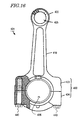
- FIG. 16 is a plan view schematically showing a conventional split-type connecting rod.
- the big end 30 of the connecting rod 1 has been split into the rod portion 33, which continues to the other end of the rod main body 10; and the cap portion 34, which is coupled to the rod portion 33 via bolts 40 extending through bolt holes 32.
- the rod portion 33 and the cap portion 34 are split by a fracture split technique.
- a fracture split technique is a technique in which the rod portion 33 and the cap portion 34 are integrally formed and thereafter split through brittle fracture. With this technique, through brittle fracture, minute rugged features are formed on fractured surfaces F of the rod portion 33 and the cap portion 34 in a complementary manner.
- the complementary rugged features which are present on the fractured surfaces F of the rod portion 33 and the cap portion 34 enable accurate positioning of the rod portion 33 and the cap portion 34. As the rugged features on the fractured surface F fit one another, the rod portion 33 and the cap portion 34 are more firmly coupled to each other, whereby the rigidity of the entire big end 30 is improved.
- Fatigue strength is not such an important issue for the big end 30 of the connecting rod 1. Rather, the big end 30 is required to have a high rigidity and a high elastic modulus. In the case where the aforementioned fracture split technique is used, the big end 30 should also allow easy brittle fracture. On the other hand, the small end 20 and the rod main body 10 are required to have a high fatigue strength, rather than a high rigidity and a high elastic modulus. In conventional connecting rods, it has been difficult to satisfy all of the aforementioned preferred conditions because the entire connecting rod is integrally formed from the same material.
- the cross-sectional area of the connecting rod 1 changes along a direction from the small end 20 to the big end 30 (longitudinal direction Z in FIG. 1), in such a manner that the cross-sectional area undergoes a constant increase in the rod main body 10 from the small end 20 toward the big end 30. Therefore, typically, the end RE of the curved section 30R is defined as a portion where the rate of increase of cross-sectional area changes from the aforementioned constant value (i.e., so as to become greater).
- FIGS. 11A and 11B are diagrams showing a cross section of the rod main body 10 and preferred oscillation directions.
- the big end is also inevitably formed of that same metal material. Since the above metal materials are relatively expensive, use of such an expensive material in the big end will cause an increase in the production cost, even though the big end is not required to have a high specific strength. Moreover, in order to achieve the same level of mechanical strength by using any of the above metal materials, the big end will have to become large, which will again increase the production cost.
Landscapes
- Engineering & Computer Science (AREA)
- General Engineering & Computer Science (AREA)
- Mechanical Engineering (AREA)
- Shafts, Cranks, Connecting Bars, And Related Bearings (AREA)
Abstract
Description
- The present invention relates to a connecting rod and a production method thereof. Moreover, the present invention also relates to an internal combustion engine and an automotive vehicle including such a connecting rod.
- In an internal combustion engine of an automotive vehicle, a part which is called a connecting rod (or con rod) is used for linking a crankshaft to a piston. FIG. 16 shows a
conventional connecting rod 401. The connectingrod 401 includes a bar-like rodmain body 410, asmall end 420 which is provided at one end of the rodmain body 410, and abig end 430 which is provided at the other end of the rodmain body 410. - The
small end 420, which has apiston pin hole 425 for allowing a piston pin to extend therethrough, is connected to a piston via the piston pin. On the other hand, thebig end 430, which has acrankpin hole 435 for allowing a crankpin to extend therethrough, is connected to a crankshaft via the crankpin. - The
big end 430 is split into arod portion 433 which continues from one end of the rodmain body 410, and acap portion 434 which is coupled to therod portion 433 withbolts 440. Therefore, the connectingrod 401 shown in FIG. 16 is referred to as a split-type connecting rod. Other types of connecting rods are also known whose big end is not split. - Conventionally, steel has widely been used as a material for connecting rods. Recently, use of a titanium alloy has been disclosed (see, for example,
Japanese Laid-Open Patent Publication No. 60-247432 - However, it has been found that using a titanium alloy as the material of a connecting rod may result in the following problems.
- Requirements on the mechanical characteristics of a connecting rod differ from region to region. For example, the small end and rod main body of a connecting rod are required to have a high strength and a high toughness so as not to undergo fatigue failure or impact failure during use. On the other hand, the big end of a connecting rod is required to be such that the inner peripheral surface of the crankpin hole does not deform due to a rotary motion of a crankshaft, so that there is little friction against a crankpin. That is, the big end must have a high rigidity and a high elastic modulus so as not to deform during a high-speed drive.
- If a titanium alloy whose elastic modulus is lower than that of steel is used as the material of a connecting rod, weight reduction may be achieved, but the rigidity of the big end will be insufficient. On the other hand, designing a connection rod to have a size for attaining sufficient rigidity will detract from the advantage of weight reduction.
- Accordingly, the inventors have contemplated using different metal materials for different regions of a connecting rod. In a connecting rod which is formed by bonding together a plurality of members which are composed of metals of different compositions, desired mechanical characteristics can be conferred to different regions of the connecting rod. For example, a metal material which is light-weight and which has a good fatigue strength may used for the small end and the rod main body, whereas a metal material which has a high rigidity and a high elastic modulus may be used for the big end, whereby weight reduction can be achieved while ensuring rigidity of the big end.
- However, the inventors have conducted detailed studies to find that adequate weight reduction may actually be difficult to achieve even with such a technique. A connecting rod transmits the explosive force from a piston to a crankshaft, and therefore is required to have a high strength. Hence, if a connecting rod is formed by bonding together a plurality of members, the joints will have a reduced strength, thus making it difficult to obtain a sufficient strength. On the other hand, if a thick connecting rod is built in order to increase the cross-sectional area at each such joint and compensate for the reduced strength, there will be a corresponding increase in its weight, which detracts from the purpose of using different metal materials.
- In order to overcome the problems described above, preferred embodiments of the present invention provide a connecting rod which has good mechanical characteristics in each of its regions, and which also attains adequate weight reduction, as well as providing a production method thereof.
- A connecting rod according to a preferred embodiment of the present invention is a connecting rod including a rod main body; a small end located at one end of the rod main body; and a big end located at another end of the rod main body, the big end including a curved section which is curved so as to become narrower toward the rod main body; wherein the big end is formed of a metal material whose composition is different from that of the rod main body, and is bonded to the rod main body, and a joint between the big end and the rod main body is located closer to the small end than is an end of the curved section facing the rod main body.
- In a preferred embodiment, the rod main body is formed of a material whose specific gravity is smaller than that of the big end.
- In another preferred embodiment, the big end and the rod main body are bonded together by friction welding.
- In another preferred embodiment, the small end and the rod main body are formed of a material whose specific strength is higher than that of the big end.
- In another preferred embodiment, the small end and the rod main body are formed of a titanium alloy, an aluminum alloy, or a magnesium alloy.
- In another preferred embodiment, the small end and the rod main body are formed of maraging steel, alloy steel, or carbon steel.
- In another preferred embodiment, the big end is formed of high-carbon steel, microalloyed steel, or sinter-forged material.
- In another preferred embodiment, the big end is formed of an iron alloy, and the small end and the rod main body are formed of a titanium alloy.
- In another preferred embodiment, an average carbon content in the big end from a surface to a depth of about 0.2mm is less than about 0.3 mass%, and a distance from the end of the curved section facing the rod main body to the joint is about 3mm or more.
- In another preferred embodiment, an average carbon content in the big end from a surface to a depth of about 0.2 mm is no less than about 0.3 mass% and no more than about 0.5 mass%, and a distance from the end of the curved section facing the rod main body to the joint is about 5mm or more.
- In another preferred embodiment, an average carbon content in the big end from a surface to a depth of about 0.2mm is more than about 0.5 mass%, and a distance from the end of the curved section facing the rod main body to the joint is about 7mm or more.
- An internal combustion engine according to another preferred embodiment of the present invention includes a connecting rod having the aforementioned construction.
- An automotive vehicle according to another preferred embodiment of the present invention includes a connecting rod having the aforementioned construction.
- A production method for a connecting rod according to another preferred embodiment of the present invention is a production method for producing a connecting rod having a rod main body, a small end formed at one end of the rod main body, and a big end formed at another end of the rod main body, including a step of preparing a first member formed of a first metal material, a step of preparing a second member formed of a second metal material whose composition is different from that of the first metal material, and a step of bonding together the first member and the second member by linear friction welding.
- In another preferred embodiment, the big end includes a curved section which is curved so as to become narrower toward the rod main body, and the bonding step is performed in such a manner that a joint between the first member and the second member is located closer to the small end than is an end of the curved section facing the rod main body.
- In another preferred embodiment, the big end has a throughhole through which a crankpin is inserted, and the bonding step is performed in such a manner that the first member and the second member are rubbed against each other along a direction which is substantially perpendicular to a center axis direction of the throughhole and to a direction in which the rod main body extends.
- In another preferred embodiment, the big end has a throughhole through which a crankpin is inserted, and the bonding step is performed in such a manner that the first member and the second member are rubbed against each other along a center axis direction of the throughhole.
- In a connecting rod according to the preferred embodiments of the present invention, the small end and the rod main body are formed of a metal whose composition is different from that of the big end. Therefore, different mechanical characteristics can be achieved for the small end and the rod main body and for the big end, thus providing good mechanical characteristics for each region of the connecting rod.
- Moreover, in a connecting rod according to a preferred embodiment of the present invention, a joint between the big end and the rod main body is located closer to the small end than is an end of the curved section of the big end facing the rod main body. Thus, in a connecting rod according to the present preferred embodiment, the joint is provided at a position which is offset from the end of the curved section where stress concentrates the most. Therefore there is less need for increasing the cross-sectional area of the joint in order to compensate for a reduced strength due to bonding. Therefore, an adequate weight reduction can be achieved while ensuring good mechanical characteristics.
- Other features, elements, processes, steps, characteristics and advantages of the present invention will become more apparent from the following detailed description of preferred embodiments of the present invention with reference to the attached drawings.
- FIG. 1 is a plan view schematically showing a connecting rod according to a preferred embodiment of the present invention.
- FIG. 2 is a perspective view schematically showing a connecting rod according to a preferred embodiment of the present invention.
- FIG. 3A is a diagram illustrating a minimum thickness of a small end. FIG. 3B is a view illustrating dimensions A1 and A2.
- FIG. 4 is an illustration for explaining linear friction welding.
- FIG. 5 is a graph showing a relationship between a distance from a curved section end to a joint, fatigue strength of the curved section end, and adjusted weight of a connecting rod.
- FIG. 6 is a graph showing a relationship between a distance from a curved section end to a joint, fatigue strength of the curved section end, and adjusted weight of a connecting rod.
- FIG. 7 is a graph showing a relationship between a distance from a curved section end to a joint, fatigue strength of the curved section end, and adjusted weight of a connecting rod.
- FIGS. 8A and 8B are plan views schematically showing a first member and a second member which are prepared in a production method for a connecting rod according to another preferred embodiment of the present invention.
- FIG. 9 is a diagram schematically showing a friction welding apparatus with which to perform linear friction welding.
- FIG. 10 is a schematic illustration of a first holder and a second holder which are included in a friction welding apparatus.
- FIGS. 11A and 11B are diagrams for explaining preferred oscillation directions in a bonding step.
- FIG. 12A is a plan view showing the area of a joint in a connecting rod. FIG. 12B is a cross-sectional view taken along
line 12B-12B' in FIG. 12A. - FIG. 13A is a plan view showing the area of a joint in a connecting rod. FIG. 13B is a cross-sectional view taken along
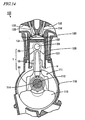
line 13B-13B' in FIG. 13A. - FIG. 14 is a cross-sectional view schematically showing an exemplary engine which incorporates a connecting rod according to a preferred embodiment of the present invention.
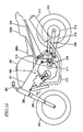
- FIG. 15 is a cross-sectional view schematically showing a motorcycle which incorporates the engine shown in FIG. 14.
- FIG. 16 is a plan view schematically showing a conventional split-type connecting rod.
- Hereinafter, preferred embodiments of the present invention will be described with reference to the accompanying drawings. Note that the present invention is not to be limited to the preferred embodiments below.
- FIG. 1 shows a connecting
rod 1 according to the present preferred embodiment. As shown in FIG. 1, the connectingrod 1 includes a bar-like rodmain body 10, asmall end 20 which is provided at one end of the rodmain body 10, and abig end 30 which is provided at the other end of the rodmain body 10. - The
small end 20 has a throughhole (called a "piston pin hole") 25 for allowing a piston pin to extend therethrough. On the other hand, thebig end 30 has a throughhole (called a "crankpin hole") 35 for allowing a crankpin to extend therethrough. Thecrankpin hole 35 typically has a larger diameter than that of thepiston pin hole 25. - In the following descriptions, the direction in which the rod
main body 10 extends will be referred to as the "longitudinal direction", and the direction of a center axis of thecrankpin hole 35 will be referred to as the "axial direction". Moreover, a direction which is orthogonal to the longitudinal direction and the axial direction will be referred to as the "width direction". In the figures, the longitudinal direction is shown by arrow Z, the axial direction is shown by arrow X, and the width direction is shown by arrow Y. - As shown in FIG. 2, the
big end 30 of the connectingrod 1 has been split into therod portion 33, which continues to the other end of the rodmain body 10; and thecap portion 34, which is coupled to therod portion 33 viabolts 40 extending through bolt holes 32. It is preferable that therod portion 33 and thecap portion 34 are split by a fracture split technique. A fracture split technique is a technique in which therod portion 33 and thecap portion 34 are integrally formed and thereafter split through brittle fracture. With this technique, through brittle fracture, minute rugged features are formed on fractured surfaces F of therod portion 33 and thecap portion 34 in a complementary manner. The complementary rugged features which are present on the fractured surfaces F of therod portion 33 and thecap portion 34 enable accurate positioning of therod portion 33 and thecap portion 34. As the rugged features on the fractured surface F fit one another, therod portion 33 and thecap portion 34 are more firmly coupled to each other, whereby the rigidity of the entirebig end 30 is improved. - The connecting
rod 1 of the present preferred embodiment differs from a conventional connecting rod in that thebig end 30 is formed of a metal whose composition is different from that of thesmall end 20 and the rodmain body 10, and is bonded to the rodmain body 10. FIGS. 1 and 2 show the joint between thebig end 30 and the rodmain body 10 at reference character W. - Fatigue strength is not such an important issue for the
big end 30 of the connectingrod 1. Rather, thebig end 30 is required to have a high rigidity and a high elastic modulus. In the case where the aforementioned fracture split technique is used, thebig end 30 should also allow easy brittle fracture. On the other hand, thesmall end 20 and the rodmain body 10 are required to have a high fatigue strength, rather than a high rigidity and a high elastic modulus. In conventional connecting rods, it has been difficult to satisfy all of the aforementioned preferred conditions because the entire connecting rod is integrally formed from the same material. - In the present preferred embodiment, since the
big end 30 is formed of a metal whose composition is different from that of thesmall end 20 and the rodmain body 10, good mechanical characteristics can be achieved in each region of the connectingrod 1. Specifically, by forming thebig end 30 from a metal material which has a high rigidity and a high elastic modulus (and further allows easy fracture split), and forming thesmall end 20 and the rodmain body 10 from a metal material which has a high fatigue strength, a preferred distribution (a distribution which was not available in any conventional connecting rod) can be conferred to the mechanical characteristics of the connectingrod 1. Furthermore, by forming thesmall end 20 and the rodmain body 10 from a metal material whose specific gravity (i.e., density) is smaller than that of thebig end 30, the weight of the entire connectingrod 1 can be reduced while ensuring rigidity of thebig end 30. For example, by forming thebig end 30 from an iron alloy and forming thesmall end 20 and the rodmain body 10 from a titanium alloy, a connectingrod 1 which is light-weight and has good mechanical characteristics can be obtained. - The connecting
rod 1 of the present preferred embodiment is further defined by the location of the joint W between thebig end 30 and the rodmain body 10. As shown in FIG. 1, thebig end 30 includes acurved section 30R which is curved on either side so as to become narrower toward the rod main body 10 (i.e., which is hollowed toward the inside). The joint W is located closer to thesmall end 20 than is an end RE of thecurved section 30R, the end RE being an end of thecurved section 30R that is facing (adjacent to) the rodmain body 10. - In order to maximize the weight reduction effect by using a metal material whose specific gravity is smaller than that of the
big end 30 as the material of thesmall end 20 and the rodmain body 10, it might seem preferable to perform bonding at the end RE of thecurved section 30R (i.e., so that the end RE of thecurved section 30R would coincide with the joint W). However, when a plurality of members are bonded together, their joint W will have a reduced strength. Therefore, if bonding were to be performed at the end RE of thecurved section 30R, which is subjected to the greatest stress within the connectingrod 1, it would be necessary to increase the cross-sectional area of the joint W in order to compensate for the insufficient strength. This would result in an increased weight, thus hindering a desired weight reduction. - On the other hand, according to the present preferred embodiment, the joint W is provided at a position which is offset from the end RE of the
curved section 30R, at which end RE stress concentrates the most. As a result, it is unnecessary to increase the cross-sectional area of the joint W in order to compensate for the decrease in strength which is caused by bonding. Therefore, an adequate weight reduction can be achieved while ensuring good mechanical characteristics. - Note that the cross-sectional area of the connecting
rod 1 changes along a direction from thesmall end 20 to the big end 30 (longitudinal direction Z in FIG. 1), in such a manner that the cross-sectional area undergoes a constant increase in the rodmain body 10 from thesmall end 20 toward thebig end 30. Therefore, typically, the end RE of thecurved section 30R is defined as a portion where the rate of increase of cross-sectional area changes from the aforementioned constant value (i.e., so as to become greater). - The bonding between the
big end 30 and the rodmain body 10 may be performed by various methods, but it is preferable to use friction welding. Friction welding is a technique in which members to be bonded are rapidly rubbed against each other so as to be softened by the frictional heat, while a pressure is concurrently applied to effect bonding. A fusion welding technique may also be used, but using a fusion welding technique for the bonding of different materials may result in brittle alloys or intermetallic compounds being formed. Friction welding can suppress formation of such brittle alloys and intermetallic compounds, and therefore can be used for a favorable bonding of various combinations of different materials. Although a method which utilizes an intermediary member (third member), e.g., welding or brazing, may also be used for the bonding, a friction welding technique will facilitate bonding of different metal materials with a high strength, as compared to any method which utilizes an intermediary member. - Moreover, with a friction welding technique, bonding can be performed with a good positional precision (e.g., a precision of about 0.05 mm), which will enable further weight reduction. A conventional connecting rod is integrally forged, in its entirety, and therefore has been difficult to form with a precise three-dimensional positional relationship between the piston pin hole and the crankpin hole. This has led to the need to increase the thickness of the connecting rod so as to account for such misalignment. For example, it has been necessary to increase the minimum thickness Tmin of the small end shown in FIG. 3A and dimensions A1 and A2 shown in FIG. 3B. On the other hand, friction welding helps to reduce such misalignment. Specifically, the conventional misalignment values of about 0.2 mm along the axial direction X and about 0.3 mm along the width direction Y and the longitudinal direction Z can be reduced to about 0.05 mm. Therefore, it is unnecessary to make the connecting
rod 1 thick so as to account for such misalignment, whereby further weight reduction can be achieved. Weight reduction of the connectingrod 1 results in a reduced reciprocating weight, which will allow the weights of the crankshaft and balancer to also be reduced, thus enabling weight reduction of the internal combustion engine and the entire automotive vehicle. - Moreover, friction welding does not allow much of a gap at the joint W, and makes it unnecessary to use an intermediary member, thereby improving thermal conduction from the
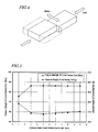
small end 20 to thebig end 30. Furthermore, since no intermediary member is required, the facilities for performing the bonding step can be simplified, thus making it easy to achieve automation of the bonding step. - Friction welding is generally classified into rolling friction welding, in which one (or both) of the members to be bonded is allowed to rotate; and linear friction welding, in which one of the members to be bonded to is allowed to linearly reciprocate as shown in FIG. 4. Since the connecting
rod 1 generally does not have a circular cross section, it is preferable to use linear friction welding. - Note that, even when bonding is performed by friction welding, the metallographical structure at the joint W will be changed, and thus the strength of the joint W will somewhat decrease. However, by offsetting the position of the joint W from the curved section end RE (where stress concentrates the most) as in the present preferred embodiment, there will be less need for increasing the cross-sectional area to compensate for such a reduced strength. Moreover, as the distance D from the end RE of the
curved section 30R to the joint W (see FIG. 1) becomes longer, the curved section end RE becomes less likely to be affected by any change in the metallographical structure caused by bonding, thus minimizing a decrease in fatigue strength at the curved section end RE. Hereinafter, a preferred range of the distance D from the curved section end RE to the joint W will be specifically described with respect to cases where thebig end 30 is preferably formed of an iron alloy and thesmall end 20 and the rodmain body 10 are formed of a titanium alloy. - Table 1 shows the following data, where the distance D (mm) is varied: weight (g) of the entire connecting rod, Vickers hardness (HV) of the curved section end RE at a depth of about 0.1 mm, and fatigue strength (MPa) of the curved section end RE. Note that the data shown in Table 1 was obtained by using as the material of the
big end 30, an iron alloy (steel) whose average carbon content from the surface to a depth of about 0.2 mm is less than 0.3 mass%, and as the material of thesmall end 20 and the rodmain body 10, a titanium alloy whose composition is Ti-6Al-4V (i.e., containing about 6 mass% Al and about 4 mass% V).Table 1 average carbon content in big end from surface to depth of 0.2 mm:< 0.3 mass% distance from curved section end to joint (mm) weight of connecting rod (g) hardness of curved section end (HV) fatigue strength of curved section end (MPa) weight of connecting rod, with adjusted cross-sectional area of joint (g) weight of connecting rod, when entirely formed of steel (g) 1 266.0 630 756 278.5 338 3 267.0 720 864 268.9 5 268.0 720 864 268.0 7 268.9 720 864 268.9 9 269.8 720 864 269.8 11 270.6 720 864 270.6 - Firstly, looking at the weight of the connecting
rod 1, it can be seen that the weight of the connectingrod 1 decreases as the distance D becomes shorter. This is because a greater portion is formed of a titanium alloy as the distance D becomes shorter. - However, looking at the hardness and fatigue strength of the curved section end RE, it can be seen that the curved section end RE has a low hardness and a low fatigue strength when the distance D is too short. This is because the curved section end RE is affected by a change in the metallographical structure of the joint W when the distance D is too short.
- Table 1 also shows the weight (hereinafter "adjusted weight") of the connecting
rod 1 when the cross-sectional area of the joint W is adjusted (or specifically, increased) so that a preferable fatigue strength is obtained at the curved section end RE. Looking at the adjusted weight, it can be seen that there is actually an increase in the weight when the distance D is too short. - FIG. 5 shows a relationship between the distance D from the curved section end RE to the joint W, fatigue strength of the curved section end RE, and adjusted weight of the connecting
rod 1. - From FIG. 5, it can be seen that fatigue strength improves as the distance D becomes longer, and that the fatigue strength takes a virtually constant value when the distance D is about 3 mm or more. This means that, when the distance D is about 3 mm or longer, the curved section end RE is hardly affected by a change in the metallographical structure of the joint W. There is also a corresponding decrease in the adjusted weight as the distance D becomes longer, indicating that an adequate weight reduction effect is obtained when the distance D is about 3 mm or more. Since the weight of the connecting
rod 1 when it is entirely formed of steel is 338 g as shown in Table 1, a weight reduction of about 20% can be obtained by setting the distance D to be about 3 mm or more in the illustrated example. Note that, as can also be seen from FIG. 5, the distance D may also be less than about 3 mm so long as it is sufficiently close to 3 mm (about 2.5 mm or more), whereby a practically sufficient weight reduction effect can be obtained. - Next, Table 2 and FIG. 6 show data in the case where the material of the
big end 30 is an iron alloy (steel) whose average carbon content from the surface to a depth of about 0.2 mm is no less than about 0.3 mass% and no more than about 0.5 mass%. The material of thesmall end 20 and the rodmain body 10 is the same as that in the connecting rod whose data is shown in Table 1 and FIG. 5.Table 2 average carbon content in big end from surface to depth of 0.2 mm:0.3 mass%≦ X ≦ 0.5 mass% distance from curved section end to joint (mm) weight of connecting rod (g) hardness of curved section end (HV) fatigue strength of curved section end (MPa) weight of connecting rod, with adjusted cross-sectional area of joint (g) weight of connecting rod, when entirely formed of steel (g) 1 266.0 620 744 288.0 338 3 267.0 660 792 278.5 5 268.0 720 864 268.0 7 268.9 720 864 268.9 9 269.8 720 864 269.8 11 270.6 720 864 270.6 - From Table 2 and FIG. 6, it can be seen that fatigue strength improves as the distance D becomes longer, and that the fatigue strength takes a virtually constant value when the distance D is about 5 mm or more. It can also be seen that the adjusted weight decreases as the distance D increases, indicating that an adequate weight reduction effect is obtained when the distance D is about 5 mm or more. Therefore, in this case, the curved section end RE acquires a sufficiently high fatigue strength when the distance D from the curved section end RE to the joint W is 5 mm or more, whereby an adequate weight reduction can be achieved. Note that, as can also be seen from FIG. 6, the distance D may also be less than about 5 mm so long as it is sufficiently close to 5 mm (about 4.5 mm or more), whereby a practically sufficient weight reduction effect can be obtained.
- Next, Table 3 and FIG. 7 show data in the case where the material of the
big end 30 is an iron alloy (steel) whose average carbon content from the surface to a depth of about 0.2 mm is more than about 0.5 mass%. The material of thesmall end 20 and the rodmain body 10 is the same as that in the connecting rod whose data is shown in Table 1 and FIG. 5.Table 3 average carbon content in big end from surface to depth of 0.2 mm:> 0.5 mass% distance from curved section end to joint (mm) weight of connecting rod (g) hardness of curved section end (HV) fatigue strength of curved section end (MPa) weight of connecting rod, with adjusted cross-sectional area of joint (g) weight of connecting rod, when entirely formed of steel (g) 1 266.0 550 660 305.6 338 3 267.0 620 744 288.3 5 268.0 660 792 279.8 7 268.9 720 864 268.9 9 269.8 720 864 269.8 11 270.6 720 864 270.6 - From Table 3 and FIG. 7, it can be seen that fatigue strength improves as the distance D becomes longer, and that the fatigue strength takes a virtually constant value when the distance D is about 7 mm or more. It can also be seen that the adjusted weight decreases as the distance D increases, indicating that an adequate weight reduction effect is obtained when the distance D is about 7 mm or more. Therefore, in this case, the curved section end RE acquires a sufficiently high fatigue strength when the distance D from the curved section end RE to the joint W is about 7 mm or more, whereby an adequate weight reduction can be achieved. Note that, as can also be seen from FIG. 7, the distance D may also be less than about 7 mm so long as it is sufficiently close to 7 mm (about 6.5 mm or more), whereby a practically sufficient weight reduction effect can be obtained.
- As specifically described in Tables 1 to 3 and FIGS. 5 to 7, the connecting
rod 1 according to the above-mentioned preferred embodiments provides an unexpected effect such that, by offsetting the joint W toward thesmall end 20, the weight of the connectingrod 1 can be conversely reduced. - Note that there is no particular upper limit to the distance D in each case. However, if the distance D is too long, the portion which is formed of a titanium alloy will become smaller, thus resulting in an extra increase in weight. Therefore, it is preferable that the distance D is about 10 mm or less.
- Next, a production method for the connecting
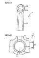
rod 1 according to another preferred embodiment will be described. - First, as shown in FIG. 8A, a first member P1 is prepared which is formed of a titanium alloy and includes the
small end 20 and the rodmain body 10. In addition, as shown in FIG. 8B, a second member P2 is prepared which is formed of an iron alloy and includes thebig end 30. The first member P1 and the second member P2 can be formed by various known techniques including a forging step, a machining step, a heat treatment step, and the like. - Next, the first member P1 and the second member P2 which have been prepared are bonded together by linear friction welding. FIG. 9 shows a
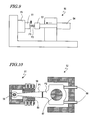
friction welding apparatus 50 with which to perform linear friction welding. - The
friction welding apparatus 50 includes afirst holder 51 for holding the first member P1, asecond holder 52 for holding the second member P2, anactuator 53 which is linked to thefirst holder 51, and ahydraulic cylinder 54 which is linked to thesecond holder 52. As theactuator 53, a hydraulic servo type or electric motor type may be used, for example. While causing the first member P1 to linearly reciprocate with theactuator 53, the second member P2 is pressed against the first member P1 by using thehydraulic cylinder 54. Thus, friction welding is performed, whereby the first member P1 and the second member P2 are bonded together. This bonding step is performed in such a manner that the joint W between the first member P1 and the second member P2 is located closer to thesmall end 20 than is the end RE (facing the rod main body 10) of thecurved section 30R. Burrs are cut off the joint W after the bonding, whereby the connectingrod 1 is finished. - FIG. 10 shows exemplary first and
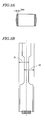
second holders first holder 51 shown in FIG. 10 firmly holds the first member P1 with apin 55 which is inserted through thepiston pin hole 25 and aclamp 56 which clamps the rodmain body 10 on both sides. Thesecond holder 52 shown in FIG. 10 firmly holds the second member P2 with apin 57 which is inserted through thecrankpin hole 35 andbolts 58 which are inserted in bolt holes of thebig end 30. - Now, preferred oscillation directions of the first member P1 in the bonding step will be described with reference to FIGS. 11A and 11B. FIGS. 11A and 11B are diagrams showing a cross section of the rod
main body 10 and preferred oscillation directions. - Preferably, the bonding step is performed in such a manner that the first member P1 and the second member P2 are rubbed against each other along the width direction D1 of the connecting rod 1 (corresponding to the direction Y in FIG. 1), as shown in FIG. 11A. Since the width direction D1 is the direction along which the highest moment occurs in the plane which is parallel to the joint surface (i.e., having the highest rigidity), allowing the first member P1 to oscillate along the width direction D1 helps to reduce elastic deformation and plastic deformation during bonding. As a result, the amplitude which is required during bonding can be decreased, and the bonding precision can be improved.
- Alternatively, as shown in FIG. 11B, it is also preferable to perform the bonding step in such a manner that the first member P1 and the second member P2 are rubbed against each other along the axial direction D2 (corresponding to the direction X in FIG. 1). Since the axial direction D2 is the direction along which the lowest moment occurs in the plane which is parallel to the joint surface (i.e., having the lowest rigidity), allowing the first member P1 to oscillate along the axial direction D2 makes it easier for the members to elastically deform during bonding. Thus, the joint surfaces can be better brought together, thus reducing the gap at the joint W. As a result, the bonding strength can be improved.
- The selection as to which one of the width direction D1 or the axial direction D2 the first member P1 should oscillate can be made depending on the shapes and materials of the members near the joint W, the required performance (e.g., which one of bonding precision or bonding strength is regarded as important), and the like.
- Note that, although the production method has been described with respect to an exemplary case where the first member P1 is allowed to oscillate, the second member P2 may be allowed to oscillate instead of the first member P1.
- Next, preferred cross-sectional shapes near the joint W will be described with reference to FIGS. 12A, 12B, 13A, and 13B.
- As shown in FIGS. 12A and 12B, if an H-shaped cross-sectional shape is used at the joint W, weight reduction can be ensured without decreasing the buckling strength (cross-sectional moment). Moreover, as shown in FIGS. 13A and 13B, if a generally rectangular cross-sectional shape is used at the joint W, the area of the joint surface can be increased without decreasing the buckling strength (cross-sectional moment), and therefore the bonding strength can be improved.
- Although the present preferred embodiment illustrates an example where the
small end 20 and the rodmain body 10 are formed of a titanium alloy and thebig end 30 is preferably formed of an iron alloy (steel), the present invention is not limited thereto. - It is preferable that the
small end 20 and the rodmain body 10 are formed of a titanium alloy, an aluminum alloy, or a magnesium alloy, for example. Since these metal materials have a high specific strength, it becomes possible to reduce the weight of the connectingrod 1 by using such metal materials. - In a conventional connecting rod, in the case where the small end and the rod main body are formed of any of such metal materials, the big end is also inevitably formed of that same metal material. Since the above metal materials are relatively expensive, use of such an expensive material in the big end will cause an increase in the production cost, even though the big end is not required to have a high specific strength. Moreover, in order to achieve the same level of mechanical strength by using any of the above metal materials, the big end will have to become large, which will again increase the production cost.
- According to the preferred embodiments of the present invention, the
big end 30 is formed of a metal material whose composition is different from that of thesmall end 20 and the rodmain body 10. Therefore, by forming only thesmall end 20 and the rodmain body 10 from a titanium alloy, an aluminum alloy, or a magnesium alloy, the amount of such an expensive metal material can be reduced from the conventional level corresponding to the amount which would have been used for thebig end 30. As a result, the production cost can be reduced. Especially when the connecting rod is formed by forging, the material used for the small end has conventionally had a low production yield because of the requirement to match the size of the big end. The preferred embodiments of the present invention are also effective for improving the production yield. - In the case where the big end is formed of a titanium alloy, an aluminum alloy, or a magnesium alloy, sticking is likely to occur due to sliding against the crank side surfaces, thus resulting in the need to perform a surface treatment or use thrust washers. According to the preferred embodiments of the present invention, there is less need for a surface treatment or thrust washers.
- Alternatively, it would also be preferable to form the
small end 20 and the rodmain body 10 from maraging steel, alloy steel, or carbon steel. Each of these metal materials has a high fatigue strength, and therefore can be suitably used as a material for thesmall end 20 and the rodmain body 10. - In a conventional connecting rod, in the case where the small end and the rod main body are formed of any of such metal materials, the big end is also inevitably formed of that metal material. Since the above metal materials are difficult to be processed after a heat treatment, if any of such materials is used (although the big end is not required to have a high fatigue strength), it will be difficult to process the big end, in which a greater amount of material must be processed than in the small end.
- According to the preferred embodiments of the present invention, by forming only the
small end 20 and the rodmain body 10 from maraging steel, alloy steel, or carbon steel, processing of thebig end 30 can be facilitated. Moreover, since these metal materials are also relatively expensive, the production cost can be reduced because of not having to use such metal materials for thebig end 30. - It is preferable that the
big end 30 is formed of high-carbon steel, microalloyed steel, or a sinter-forged material, for example. These metal materials have a high elastic modulus and are brittle, and therefore facilitate fracture split. - In a conventional connecting rod, in the case where the big end is formed of any of such metal materials, the small end and the rod main body are also inevitably formed of that metal material. Since the above metal materials have a relatively low fatigue strength, fatigue failure will be a problem if the small end and the rod main body are formed of any of such metal materials.
- According to the preferred embodiments of the present invention, by forming only the
big end 30 from high-carbon steel, microalloyed steel, or a sinter-forged material, it can be ensured that fatigue failure of thesmall end 20 and the rodmain body 10 is not a problem. If thebig end 30 is formed of the above metal materials which facilitate fracture split, the fracture split step can be simplified. Specifically, the cooling step can be omitted, formation of a fracture beginning trench can be simplified, and the output power of fracturing facilities can be reduced. Moreover, if thebig end 30 is formed of any of the above metal materials having a high elastic modulus, deformation of thebig end 30 can be minimized, so that sticking at thebig end 30 can be prevented. - As exemplary combinations of metal materials having different compositions, the above-mentioned preferred embodiments have illustrated combinations of alloys whose base metals are different. However, possible combinations of metal materials are not limited thereto. Any combination including alloy materials having the same base metal may also be used. For example, a combination of iron alloys, e.g., SCM435 and maraging steel, may be used.
- Although the above-mentioned preferred embodiment has illustrated friction welding as a preferable method for bonding together the
big end 30 and the rodmain body 10, it is also preferable to use an electron beam welding technique or a laser welding technique. With these methods, brittle alloys and/or intermetallic compounds (which lead to lower strength), are unlikely to occur because the amount of melting is small, and it is unnecessary to use any intermediary members (third members). Therefore, these methods can also be used to favorably bond together thebig end 30 and the rodmain body 10 which are formed of metal materials of different compositions. Moreover, use of an electron beam welding technique or a laser welding technique provides an advantage of further improved positional precision (e.g., up to about 0.01 mm) since the workpiece is not moved. There is also provided an advantage in that automation of the bonding step is easy. - Although the above-mentioned preferred embodiments have illustrated a split-type connecting rod, the present invention is also suitably used for a connecting rod of the type whose big end is not split.
- The connecting
rod 1 according to the above-mentioned preferred embodiments can be broadly used in various types of internal combustion engines (engines) which are intended for automotive vehicles or other mechanical applications. FIG. 14 shows an example of anengine 100 which incorporates the connectingrod 1 of the above-mentioned preferred embodiments. - The
engine 100 includes acrankcase 110, acylinder block 120, and acylinder head 130. - A
crankshaft 111 is accommodated in thecrankcase 110. Thecrankshaft 111 has acrankpin 112 and acrank web 113. - The
cylinder block 120 is provided above thecrankcase 110. Acylinder sleeve 121 having a cylindrical shape is fitted within thecylinder block 120, such that apiston 122 is allowed to reciprocate inside thecylinder sleeve 121. - The
cylinder head 130 is provided above thecylinder block 120. In conjunction with thepiston 122 and thecylinder sleeve 121 in thecylinder block 120, thecylinder head 130 defines acombustion chamber 131. Thecylinder head 130 has anintake port 132 and anexhaust port 133. Anintake valve 134 for supplying a mixture to the interior of thecombustion chamber 131 is provided within theintake port 132, and an exhaust valve 135 for enabling evacuation of thecombustion chamber 131 is provided within theexhaust port 133. - The
piston 122 and thecrankshaft 111 are linked via the connectingrod 1. Specifically, apiston pin 123 of thepiston 122 is inserted in the throughhole (piston pin hole) of thesmall end 20 of the connectingrod 1, and thecrankpin 112 of thecrankshaft 111 is inserted in the throughhole (crankpin hole) of thebig end 30, thus linking thepiston 122 and thecrankshaft 111 together. A bearingmetal 114 is provided between the inner peripheral surface of the throughhole of thebig end 30 and thecrankpin 112. The bearingmetal 114 is attached to thebig end 30 by bearing attaching grooves. - Since the connecting
rod 1 according to the preferred embodiments of the present embodiment can achieve an adequate weight reduction as already described above, theengine 100 can smoothly rise to a high revolution, and has a reduced fuel consumption. - FIG. 15 shows a motorcycle which incorporates the
engine 100 shown in FIG. 14. - In the motorcycle shown in FIG. 15, a
head pipe 302 is provided at the front end of abody frame 301. To thehead pipe 302,handlebars 305 are attached at one end and afront fork 303 is attached at another end so as to be capable of swinging in the right-left direction of the vehicle. At the lower end of thefront fork 303, afront wheel 304 is supported so as to be capable of rotating. - A
seat rail 306 is attached at an upper portion of the rear end of thebody frame 301 so as to extend in the rear direction. Afuel tank 307 is provided on thebody frame 301, and amain seat 308a and atandem seat 308b are provided on theseat rail 306. -
Rear arms 309 extending in the rear direction are attached to the rear end of thebody frame 301. At the rear end of therear arms 309, arear wheel 310 is supported so as to be capable of rotating. - At the central portion of the
body frame 301, theengine 100 shown in FIG. 14 is mounted. Theengine 100 incorporates the connectingrod 1 of the preferred embodiments of the present invention. Aradiator 311 is provided in front of theengine 100. Anexhaust pipe 312 is connected to an exhaust port of theengine 100, and amuffler 313 is attached to the rear end of theexhaust pipe 312. - A
transmission 315 is linked to theengine 100. Drivingsprockets 317 are attached on anoutput axis 316 of thetransmission 315. The drivingsprockets 317 are linked torear wheel sprockets 319 of therear wheel 310 via achain 318. Thetransmission 315 and thechain 318 function as a transmitting mechanism for transmitting the motive power generated in theengine 100 to the driving wheel. - Since the motorcycle shown in FIG. 15 uses the
engine 100, which incorporates the connectingrod 1 of the preferred embodiments of the present invention, excellent performance can be obtained. - According to the preferred embodiments of the present invention, a connecting rod which has good mechanical characteristics for each of its regions and which can achieve adequate weight reduction is provided.
- A connecting rod according to the preferred embodiments of the present invention can be broadly used in various types of internal combustion engines (e.g., an engine for an automotive vehicle).
- While the present invention has been described with respect to preferred embodiments thereof, it will be apparent to those skilled in the art that the disclosed invention may be modified in numerous ways and may assume many embodiments other than those specifically described above. Accordingly, it is intended by the appended claims to cover all modifications of the invention that fall within the true spirit and scope of the invention.
Claims (17)
- A connecting rod comprising:a rod main body, a small end located at one end of the rod main body and a big end located at another end of the rod main body, the big end including a curved section which is curved so as to become narrower toward the rod main body; whereinthe big end is formed of a metal material whose composition is different from that of the rod main body, and is bonded to the rod main body; anda joint between the big end and the rod main body is located closer to the small end than is an end of the curved section facing the rod main body.
- The connecting rod of claim 1, wherein the rod main body is formed of a material whose specific gravity is smaller than that of the big end.
- The connecting rod of claim 1 or 2, wherein the big end and the rod main body are bonded together by friction welding.
- The connecting rod of any of claims 1 to 3, wherein the small end and the rod main body are formed of a material whose specific strength is higher than that of the big end.
- The connecting rod of any of claims 1 to 4, wherein the small end and the rod main body are formed of a titanium alloy, an aluminum alloy, or a magnesium alloy.
- The connecting rod of any of claims 1 to 3, wherein the small end and the rod main body are formed of maraging steel, alloy steel, or carbon steel.
- The connecting rod of any of claims 1 to 6, wherein the big end is formed of high-carbon steel, microalloyed steel, or sinter-forged material.
- The connecting rod of any of claims 1 to 3, wherein the big end is formed of an iron alloy, and the small end and the rod main body are formed of a titanium alloy.
- The connecting rod of claim 8, wherein an average carbon content in the big end from a surface to a depth of about 0.2mm is less than about 0.3 mass%, and a distance from the end of the curved section facing the rod main body to the joint is about 3 mm or more.
- The connecting rod of claim 8, wherein an average carbon content in the big end from a surface to a depth of about 0.2mm is no less than about 0.3 mass% and no more than about 0.5 mass%, and a distance from the end of the curved section facing the rod main body to the joint is about 5mm or more.
- The connecting rod of claim 8, wherein an average carbon content in the big end from a surface to a depth of about 0.2mm is more than about 0.5 mass%, and a distance from the end of the curved section facing the rod main body to the joint is about 7mm or more.
- An internal combustion engine comprising the connecting rod of any of claims 1 to 11.
- An automotive vehicle comprising the internal combustion engine of claim 12.
- A production method for producing a connecting rod having a rod main body, a small end formed at one end of the rod main body and a big end formed at another end of the rod main body, comprising:a step of preparing a first member formed of a first metal material;a step of preparing a second member formed of a second metal material whose composition is different from that of the first metal material; anda step of bonding together the first member and the second member by linear friction welding.
- The production method of claim 14, wherein the big end includes a curved section which is curved so as to become narrower toward the rod main body; and
the bonding step is performed in such a manner that a joint between the first member and the second member is located closer to the small end than is an end of the curved section facing the rod main body. - The production method of claim 14 or 15, wherein the big end has a throughhole through which a crankpin may be inserted; and
the bonding step is performed in such a manner that the first member and the second member are rubbed against each other along a direction which is substantially perpendicular to a center axis direction of the throughhole and to a direction in which the rod main body extends. - The production method of claim 14 or 15, wherein the big end has a throughhole through which a crankpin may be inserted; and
the bonding step is performed in such a manner that the first member and the second member are rubbed against each other along a center axis direction of the throughhole.
Applications Claiming Priority (1)
| Application Number | Priority Date | Filing Date | Title |
|---|---|---|---|
| JP2005365746 | 2005-12-20 |
Publications (2)
| Publication Number | Publication Date |
|---|---|
| EP1801432A2 true EP1801432A2 (en) | 2007-06-27 |
| EP1801432A3 EP1801432A3 (en) | 2009-07-22 |
Family
ID=37781825
Family Applications (1)
| Application Number | Title | Priority Date | Filing Date |
|---|---|---|---|
| EP06025984A Withdrawn EP1801432A3 (en) | 2005-12-20 | 2006-12-14 | Connecting rod and method of producing the same |
Country Status (2)
| Country | Link |
|---|---|
| US (1) | US7802493B2 (en) |
| EP (1) | EP1801432A3 (en) |
Families Citing this family (6)
| Publication number | Priority date | Publication date | Assignee | Title |
|---|---|---|---|---|
| US20070261514A1 (en) * | 2006-04-13 | 2007-11-15 | Geiman Timothy E | Multi-material connecting rod |
| US8205332B2 (en) | 2008-12-08 | 2012-06-26 | Mahle International Gmbh | Method of forming a connecting rod from two dissimiliar materials by providing material blanks of dissimiliar material, joining the material blanks and subsequently forming the connecting rod |
| KR101518945B1 (en) | 2013-12-11 | 2015-05-12 | 현대자동차 주식회사 | Varialble compression ratio engine that varies compression ratio |
| US10161439B2 (en) * | 2015-04-16 | 2018-12-25 | Honda Motor Co., Ltd. | Connecting rod and manufacturing method thereof |
| US10578150B2 (en) * | 2018-07-24 | 2020-03-03 | GM Global Technology Operations LLC | Combustion engine connecting rod |
| US10769046B2 (en) | 2018-11-20 | 2020-09-08 | Rubrik, Inc. | Automated review of source code for style issues |
Citations (4)
| Publication number | Priority date | Publication date | Assignee | Title |
|---|---|---|---|---|
| DE808008C (en) * | 1950-01-28 | 1951-07-09 | Bayerische Motoren Werke Ag | Connecting rod for internal combustion engines |
| DE3238489A1 (en) * | 1982-10-18 | 1984-04-19 | Fa. Andreas Stihl, 7050 Waiblingen | Connecting rod |
| DE3339919A1 (en) * | 1983-11-04 | 1985-05-15 | Volkswagenwerk Ag, 3180 Wolfsburg | Built-up connecting rod |
| DE19812532A1 (en) * | 1998-03-21 | 1999-09-23 | Audi Ag | Connecting rod for a reciprocating machine |
Family Cites Families (21)
| Publication number | Priority date | Publication date | Assignee | Title |
|---|---|---|---|---|
| JPS5612080A (en) * | 1979-07-09 | 1981-02-05 | Hitachi Ltd | Full-enclose type motor-driven compressor |
| JPS5887238A (en) * | 1981-11-19 | 1983-05-25 | Honda Motor Co Ltd | Manufacture of fiber reinforced composite member |
| JPS60247432A (en) | 1984-05-23 | 1985-12-07 | Daido Steel Co Ltd | How to manufacture stovetops |
| BR8501182A (en) * | 1985-03-08 | 1986-10-14 | Brasil Compressores Sa | ALTERNATIVE PISTON COMPRESSOR FOR SMALL REFRIGERATION MACHINES AND THEIR ASSEMBLY PROCESS |
| JPS6224019A (en) * | 1985-07-24 | 1987-02-02 | Yamaha Motor Co Ltd | Sheet metal connecting rod |
| JPS62288713A (en) * | 1986-06-03 | 1987-12-15 | Toyota Motor Corp | Sintered connecting rod |
| JPS63199916A (en) * | 1987-02-16 | 1988-08-18 | Sumitomo Electric Ind Ltd | Composite stove |
| JPH0571526A (en) * | 1991-09-09 | 1993-03-23 | Nissan Motor Co Ltd | Internal combustion engine connect |
| JPH05196030A (en) * | 1991-11-14 | 1993-08-06 | Mitsubishi Materials Corp | Connecting rod |
| JPH05346112A (en) * | 1992-06-11 | 1993-12-27 | Mitsubishi Motors Corp | Steel/titanium connecting rod |
| US5865364A (en) | 1996-12-24 | 1999-02-02 | United Technologies Corporation | Process for linear friction welding |
| JPH11154435A (en) | 1997-11-19 | 1999-06-08 | Toshiba Corp | Joining structure of dissimilar metal materials |
| KR100315590B1 (en) | 1997-11-19 | 2002-02-28 | 니시무로 타이죠 | Joint structure of dissimilar metal materials |
| JP3453302B2 (en) | 1998-05-07 | 2003-10-06 | 三菱重工業株式会社 | Method of joining TiAl alloy member to structural steel and joining parts |
| US6244495B1 (en) | 1998-11-06 | 2001-06-12 | United Technologies Corporation | Gripper |
| JP2000310329A (en) * | 1999-04-28 | 2000-11-07 | Yamaha Motor Co Ltd | Surface hardened connecting rod |
| JP3413455B2 (en) | 2000-03-07 | 2003-06-03 | 石川島播磨重工業株式会社 | Pipe manufacturing method |
| JP2003126968A (en) | 2001-10-19 | 2003-05-08 | Ishikawajima Harima Heavy Ind Co Ltd | Linear motion friction welding method and apparatus |
| US6688512B2 (en) | 2001-12-20 | 2004-02-10 | United Technologies Corporation | Apparatus and method for friction welding |
| EP1450056B1 (en) * | 2003-02-19 | 2017-06-07 | Nissan Motor Co., Ltd. | High-strength connecting rod and method of producing same |
| JP2008095831A (en) * | 2006-10-12 | 2008-04-24 | Toyota Motor Corp | Composite connecting rod for internal combustion engine |
-
2006
- 2006-12-14 EP EP06025984A patent/EP1801432A3/en not_active Withdrawn
- 2006-12-18 US US11/611,985 patent/US7802493B2/en not_active Expired - Fee Related
Patent Citations (4)
| Publication number | Priority date | Publication date | Assignee | Title |
|---|---|---|---|---|
| DE808008C (en) * | 1950-01-28 | 1951-07-09 | Bayerische Motoren Werke Ag | Connecting rod for internal combustion engines |
| DE3238489A1 (en) * | 1982-10-18 | 1984-04-19 | Fa. Andreas Stihl, 7050 Waiblingen | Connecting rod |
| DE3339919A1 (en) * | 1983-11-04 | 1985-05-15 | Volkswagenwerk Ag, 3180 Wolfsburg | Built-up connecting rod |
| DE19812532A1 (en) * | 1998-03-21 | 1999-09-23 | Audi Ag | Connecting rod for a reciprocating machine |
Also Published As
| Publication number | Publication date |
|---|---|
| EP1801432A3 (en) | 2009-07-22 |
| US20070151409A1 (en) | 2007-07-05 |
| US7802493B2 (en) | 2010-09-28 |
Similar Documents
| Publication | Publication Date | Title |
|---|---|---|
| EP3015204B1 (en) | Production method for titanium-alloy connecting rod | |
| US20080271562A1 (en) | Connecting rod for internal combustion engine and method of manufacturing the connecting rod | |
| JPH0520182B2 (en) | ||
| JP4999828B2 (en) | Fracture split type connecting rod, internal combustion engine, transport equipment, and method of manufacturing fracture split type connecting rod | |
| CN100523528C (en) | Split connecting rod, engine and vehicle | |
| EP1724476B1 (en) | Split-type connecting rod | |
| US7802493B2 (en) | Connecting rod, internal combustion engine, automotive vehicle, and production method for connecting rod | |
| EP1769866B9 (en) | Iron species preform | |
| JP4518922B2 (en) | Split connecting rod, engine and vehicle | |
| JP2006308027A (en) | Connecting rod, internal combustion engine, motor vehicle and manufacturing method of connecting rod | |
| JP2007192399A (en) | Connecting rod, internal combustion engine, motor vehicle and manufacturing method of connecting rod | |
| JP5916829B1 (en) | Connecting rod, internal combustion engine, motor vehicle and manufacturing method of connecting rod | |
| JP4799047B2 (en) | Connecting rod, internal combustion engine equipped with the same, and motor vehicle | |
| KR100435317B1 (en) | Manufacturing method of hotforging splitsteel connectingrod | |
| JP2007003000A (en) | Connecting rod, internal combustion engine equipped with the same, and motor vehicle | |
| EP3015724B1 (en) | Connecting rod, internal combustion engine, automotive vehicle, and production method for connecting rod | |
| JPH05196030A (en) | Connecting rod | |
| CN223089443U (en) | Enhanced hydraulic motor snap ring structure and hydraulic motor using same | |
| JP5289130B2 (en) | Assembly crankshaft and manufacturing method thereof | |
| JPH11107711A (en) | Hollow integrated camshaft and method of manufacturing the same | |
| KR200290481Y1 (en) | End piece for cam shaft | |
| JP2001191126A (en) | Hollow shaft with projection and method of manufacturing the same | |
| JP2001214806A (en) | Piston for internal combustion engine and method of manufacturing the same | |
| JPH0542738U (en) | Connecting |
Legal Events
| Date | Code | Title | Description |
|---|---|---|---|
| PUAI | Public reference made under article 153(3) epc to a published international application that has entered the european phase |
Free format text: ORIGINAL CODE: 0009012 |
|
| AK | Designated contracting states |
Kind code of ref document: A2 Designated state(s): AT BE BG CH CY CZ DE DK EE ES FI FR GB GR HU IE IS IT LI LT LU LV MC NL PL PT RO SE SI SK TR |
|
| AX | Request for extension of the european patent |
Extension state: AL BA HR MK YU |
|
| PUAL | Search report despatched |
Free format text: ORIGINAL CODE: 0009013 |
|
| AK | Designated contracting states |
Kind code of ref document: A3 Designated state(s): AT BE BG CH CY CZ DE DK EE ES FI FR GB GR HU IE IS IT LI LT LU LV MC NL PL PT RO SE SI SK TR |
|
| AX | Request for extension of the european patent |
Extension state: AL BA HR MK RS |
|
| 17P | Request for examination filed |
Effective date: 20091008 |
|
| AKX | Designation fees paid |
Designated state(s): AT BE BG CH CY CZ DE DK EE ES FI FR GB GR HU IE IS IT LI LT LU LV MC NL PL PT RO SE SI SK TR |
|
| 17Q | First examination report despatched |
Effective date: 20110418 |
|
| STAA | Information on the status of an ep patent application or granted ep patent |
Free format text: STATUS: THE APPLICATION IS DEEMED TO BE WITHDRAWN |
|
| 18D | Application deemed to be withdrawn |
Effective date: 20110830 |