EP1801390A2 - Gas turbine component with de-icing construction - Google Patents
Gas turbine component with de-icing construction Download PDFInfo
- Publication number
- EP1801390A2 EP1801390A2 EP06126602A EP06126602A EP1801390A2 EP 1801390 A2 EP1801390 A2 EP 1801390A2 EP 06126602 A EP06126602 A EP 06126602A EP 06126602 A EP06126602 A EP 06126602A EP 1801390 A2 EP1801390 A2 EP 1801390A2
- Authority
- EP
- European Patent Office
- Prior art keywords
- airfoil
- gas turbine
- turbine engine
- capillary
- capillaries
- Prior art date
- Legal status (The legal status is an assumption and is not a legal conclusion. Google has not performed a legal analysis and makes no representation as to the accuracy of the status listed.)
- Granted
Links
- 238000010276 construction Methods 0.000 title 1
- 239000002131 composite material Substances 0.000 claims abstract description 34
- 230000015572 biosynthetic process Effects 0.000 claims description 4
- 239000011521 glass Substances 0.000 claims description 4
- 230000001419 dependent effect Effects 0.000 claims 5
- 239000007789 gas Substances 0.000 description 15
- 125000006850 spacer group Chemical group 0.000 description 8
- 239000000567 combustion gas Substances 0.000 description 7
- 238000000034 method Methods 0.000 description 7
- 238000009825 accumulation Methods 0.000 description 3
- 239000000446 fuel Substances 0.000 description 3
- 238000010438 heat treatment Methods 0.000 description 3
- 238000009954 braiding Methods 0.000 description 2
- 239000000463 material Substances 0.000 description 2
- 239000011347 resin Substances 0.000 description 2
- 229920005989 resin Polymers 0.000 description 2
- OKTJSMMVPCPJKN-UHFFFAOYSA-N Carbon Chemical compound [C] OKTJSMMVPCPJKN-UHFFFAOYSA-N 0.000 description 1
- 230000002411 adverse Effects 0.000 description 1
- -1 but not limited to Substances 0.000 description 1
- 229910052799 carbon Inorganic materials 0.000 description 1
- 238000005474 detonation Methods 0.000 description 1
- 239000000284 extract Substances 0.000 description 1
- 239000012530 fluid Substances 0.000 description 1
- 238000004519 manufacturing process Methods 0.000 description 1
- 239000000203 mixture Substances 0.000 description 1
- 230000004048 modification Effects 0.000 description 1
- 238000012986 modification Methods 0.000 description 1
- 230000002265 prevention Effects 0.000 description 1
- 239000010453 quartz Substances 0.000 description 1
- VYPSYNLAJGMNEJ-UHFFFAOYSA-N silicon dioxide Inorganic materials O=[Si]=O VYPSYNLAJGMNEJ-UHFFFAOYSA-N 0.000 description 1
- 239000007787 solid Substances 0.000 description 1
- 238000001721 transfer moulding Methods 0.000 description 1
- 238000011144 upstream manufacturing Methods 0.000 description 1
- XLYOFNOQVPJJNP-UHFFFAOYSA-N water Substances O XLYOFNOQVPJJNP-UHFFFAOYSA-N 0.000 description 1
Images



Classifications
-
- F—MECHANICAL ENGINEERING; LIGHTING; HEATING; WEAPONS; BLASTING
- F01—MACHINES OR ENGINES IN GENERAL; ENGINE PLANTS IN GENERAL; STEAM ENGINES
- F01D—NON-POSITIVE DISPLACEMENT MACHINES OR ENGINES, e.g. STEAM TURBINES
- F01D25/00—Component parts, details, or accessories, not provided for in, or of interest apart from, other groups
- F01D25/02—De-icing means for engines having icing phenomena
-
- F—MECHANICAL ENGINEERING; LIGHTING; HEATING; WEAPONS; BLASTING
- F01—MACHINES OR ENGINES IN GENERAL; ENGINE PLANTS IN GENERAL; STEAM ENGINES
- F01D—NON-POSITIVE DISPLACEMENT MACHINES OR ENGINES, e.g. STEAM TURBINES
- F01D5/00—Blades; Blade-carrying members; Heating, heat-insulating, cooling or antivibration means on the blades or the members
-
- F—MECHANICAL ENGINEERING; LIGHTING; HEATING; WEAPONS; BLASTING
- F02—COMBUSTION ENGINES; HOT-GAS OR COMBUSTION-PRODUCT ENGINE PLANTS
- F02C—GAS-TURBINE PLANTS; AIR INTAKES FOR JET-PROPULSION PLANTS; CONTROLLING FUEL SUPPLY IN AIR-BREATHING JET-PROPULSION PLANTS
- F02C7/00—Features, components parts, details or accessories, not provided for in, or of interest apart form groups F02C1/00 - F02C6/00; Air intakes for jet-propulsion plants
- F02C7/04—Air intakes for gas-turbine plants or jet-propulsion plants
- F02C7/047—Heating to prevent icing
-
- Y—GENERAL TAGGING OF NEW TECHNOLOGICAL DEVELOPMENTS; GENERAL TAGGING OF CROSS-SECTIONAL TECHNOLOGIES SPANNING OVER SEVERAL SECTIONS OF THE IPC; TECHNICAL SUBJECTS COVERED BY FORMER USPC CROSS-REFERENCE ART COLLECTIONS [XRACs] AND DIGESTS
- Y02—TECHNOLOGIES OR APPLICATIONS FOR MITIGATION OR ADAPTATION AGAINST CLIMATE CHANGE
- Y02T—CLIMATE CHANGE MITIGATION TECHNOLOGIES RELATED TO TRANSPORTATION
- Y02T50/00—Aeronautics or air transport
- Y02T50/60—Efficient propulsion technologies, e.g. for aircraft
Definitions
- This invention relates generally to gas turbine engines, and more particularly, to methods and apparatus for operating gas turbine engines.
- Gas turbine engines typically include an inlet, a fan, low and high pressure compressors, a combustor, and at least one turbine.
- the compressors compress air which is channeled to the combustor where it is mixed with fuel. The mixture is then ignited for generating hot combustion gases.
- the combustion gases are channeled to the turbine(s) which extracts energy from the combustion gases for powering the compressor(s), as well as producing useful work to propel an aircraft in flight or to power a load, such as an electrical generator.
- ice When engines operate in icing conditions, i.e., exposed to clouds of super-cooled water droplets, ice may accumulate on exposed engine structures. More specifically, if engines are operated within icing conditions at low power for extended periods of time, ice accumulation within the engine and over exposed engine structures may be significant. Over time, continued operation of the engine, a throttle burst from lower power operations to higher power operations, and/or vibrations due to either turbulence or asymmetry of ice accretion, may cause the accumulated ice build-up to be ingested by the high pressure compressor. Such a condition, known as an ice shed, may cause the compressor discharge temperature to be suddenly reduced.
- the corrected core speed increases in the aft stages of the high pressure compressor. This sudden increase in aft stage corrected core speed may adversely impact compressor stall margin. In some cases, it may also lead to an engine flame out.
- At least some known engines include a de-icing system to reduce ice accumulation on the gas turbine engine struts.
- the gas turbine engine component is fabricated using a composite material, it is relatively difficult to anti-ice the component using heated air that is channeled through the composite component due to low transverse thermal conductivity of the composite material. As result, relatively hot air is required to de-ice the component thus penalizing the overall engine efficiency.
- a method for manufacturing a turbine engine component includes forming a component to include a first side and an opposite second side, positioning at least one capillary adjacent to an external surface of at least one of the first and second sides, and securing the at least one capillary to the component with at least one composite layer.
- a turbine engine component in another aspect, includes a first side, an opposite second side, at least one capillary positioned adjacent to an external surface of at least one of said first and second sides, and a composite layer securing the at least one said capillary to said component.
- a gas turbine engine in a further aspect, includes at least one airfoil including a first side and an opposite second side, at least one capillary positioned adjacent to an external surface of at least one said airfoil, and a composite layer securing the at least one said capillary to said at least one airfoil.
- Figure 1 is a cross-sectional side view of an exemplary gas turbine engine 10 that has a generally longitudinally extending axis or centerline 12 extending in a forward direction 14 and an aft direction 16.
- Engine 10 includes a core engine 20 which includes a high pressure compressor 22 having a plurality of blades 23, a combustor 24, a high pressure turbine 26 having a plurality of blades 27, and a power turbine or a low pressure turbine 28 having a plurality of blades 29 all arranged in a serial, axial flow relationship.
- core engine 20 includes a compressor, a detonation chamber, and a turbine arranged in a serial, axial flow relationship.
- Engine 10 also includes a bypass duct 32 that surrounds core engine 20, and enables fluid flow to be routed downstream from core engine 20 rather than through core engine 20.
- engine 10 also includes a low-pressure compressor 34 that is axially upstream high-pressure compressor 22. More specifically, the low-pressure compressor 34 includes a plurality of blades 35 and is housed within a nacelle 36 that is supported by a plurality of circumferentially spaced apart struts 38.
- airflow enters engine 10 through struts 38 and is channeled through low-pressure compressor 34 wherein the compressed air is introduced into core engine 20.
- the air and fuel are mixed and ignited within core engine 20 to generate hot combustion gases.
- pressurized air from high pressure compressor 22 is mixed with fuel in combustor 24 and ignited, thereby generating combustion gases.
- Such combustion gases drive high pressure turbine 26 which drives high pressure compressor 22.
- the combustion gases are discharged from high pressure turbine 26 into low pressure turbine 28.
- the core airflow is discharged from low pressure turbine 28 and directed aftward towards an exhaust nozzle 40.
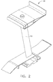
- Figure 2 is a perspective view of an exemplary airfoil 50 that may be used with the gas turbine engine shown in Figure 1.
- Figure 3 is an elevational, partly sectional view through the airfoil 50 shown in Figure 2.
- the airfoil 50 is formed as part of a stationary component, such as strut 38 for example shown in Figures 2 and 3.
- the airfoil 50 is formed as part of a rotating component, such as rotating compressor blade 35 for example.
- Figure 4 illustrates airfoil 50 manufactured as part of the exemplary strut 38.
- airfoil 50 includes a leading edge 60, an axially opposite trailing edge 62, a radially inner root (not shown), an opposite radially outer tip (not shown), and circumferentially opposite first and second sides 64 and 66 extending therebetween.
- struts 38 are aerodynamically streamlined in a generally symmetrical tear drop shape for minimizing flow obstruction.
- struts 38 are not tear drop shaped.
- Figure 5 illustrates one of the compressor blades 35 that may be manufactured in accordance with the methods described herein.
- compressor blade 35 includes airfoil 50 that includes a first contoured sidewall 70 and a second contoured sidewall 72.
- First sidewall 70 is convex and defines a suction side of airfoil 50
- second sidewall 72 is concave and defines a pressure side of airfoil 50.
- Sidewalls 70 and 72 are joined at a leading edge 74 and at an axially-spaced trailing edge 76 of airfoil 50. More specifically, airfoil trailing edge 76 is spaced chordwise and downstream from airfoil leading edge 74.
- First and second sidewalls 70 and 72 respectively, extend longitudinally or radially outward in span from a blade root (not shown) that is positioned adjacent a dovetail (not shown), to an airfoil tip (not shown).
- airfoil 50 may be fabricated to include a platform and dovetail to enable the airfoil 50 to be coupled to a rotating disk or airfoil 50 may be integrally formed with a disk conventionally referred to as a blisk without a discrete and removable dovetail.
- airfoil 50 may be utilized with a stationary component such as strut 38.
- FIG. 6 is a top cross-sectional view of airfoil 50 that may formed as part of a rotating blade or a stationary strut.
- airfoil 50 is fabricated to include a first side and a second side. More specifically, airfoil 50 includes a plurality of composite plies 80 that are bonded together to form a portion 82 of airfoil 50.
- the composite plies are fabricated using a carbon or glass composite material that are bonded together to form a portion 82 of airfoil 50.
- Airfoil 50 also includes at least one capillary 84 that is coupled to an external surface of portion 82.
- Capillary as used herein, represents a tube having a relatively small opening extending therethrough.
- airfoil 50 includes a plurality of capillaries 84, each having an opening 86 extending therethrough that is sized to receive a heated airflow therethrough, the heated airflow being sufficient to reduce or eliminate ice formation on an exterior surface 88 of airfoil 50.
- the plurality of capillaries 84 are arranged between portion 82 and an external composite layer 90 that is utilized to secure the plurality of capillaries 84 to portion 82. More specifically, the capillaries 84 are arranged such that the openings 86 extend in a radial direction along the exterior surface of portion 82. As such, a heated airflow 98 is channeled from a source, such as compressor bleed air, for example, into a radially outward end 100 of airfoil 50, through opening 86, and the heated air is then discharged through a radially inward end 102 of airfoil 50, as shown in Figure 3.
- a source such as compressor bleed air
- each capillary 84 includes a substantially cylindrical body having an inner surface 110 that defines opening 86 and an external surface 112.
- capillaries 84 are coupled between portion 82 and an external composite layer 90 such that the external surface 112 of each capillary 84 is proximate to the external surface 112 of an adjacent capillary 84.
- a first quantity of capillaries 84 are coupled to airfoil 50 to facilitate maximizing the quantity of heated airflow that is channeled through the capillaries 84 and therefore facilitate maximizing the external surface area of the airfoil that is heated.
- capillaries 84 are fabricated using a glass material such as, but not limited to, quartz, for example.
- a composite layer 90 is wrapped around airfoil portion 82.
- the airfoil assembly including airfoil portion 82, capillaries 84, and composite layer 90 are then heat treated to form a finished airfoil 50.
- FIG 7 is a top cross-sectional view of airfoil 50 that may formed as part of a rotating blade or a stationary strut.
- airfoil 50 includes a plurality of composite plies 80 that are bonded together to form a portion 82 of airfoil 50.
- Airfoil 50 also includes a sheet 150 that includes a plurality of capillaries 84 that are each interwoven with a composite material 152 to form sheet 150.
- the capillaries 84 are interwoven with composite material 152 to facilitate forming a sheet 150 of capillaries.
- sheet 150 is formed using a braiding process to provide a single braided sleeve, i.e. sheet 150, that includes a plurality of integral hollow capillary tubes 84.
- sheet 150 is biaxially braided to include unidirectional capillary tubes covering all or selected regions of the airfoil 50.
- the capillaries 84 exit the ends of the airfoil 50 and form the manifold region for entry and exit air. Sheet 150 therefore provides an operator with a more efficient means to install the capillaries 84 onto portion 82. As such, a time to fabricate airfoil 82 is reduced.
- sheet 160 including capillaries 84 is arranged between portion 82 and the external composite layer 90 that is utilized to secure the sheet 160 of capillaries to portion 82. More specifically, the capillaries 84 are arranged such that the openings 86 extend in a radial direction along the exterior surface of portion 82.
- a heated airflow 98 is channeled from a source, such as compressor bleed air, for example, into a radially outward end 100 of airfoil 50, through opening 86, and the heated air is then discharged through a radially inward end 102 of airfoil 50, as shown in Figure 3.
- a composite layer 90 is wrapped around airfoil portion 82.
- the airfoil assembly including airfoil portion 82, capillaries 84, and composite layer 90 are then heat treated to form a finished airfoil 50.
- FIG 8 is a top cross-sectional view of airfoil 50 that may formed as part of a rotating blade or a stationary strut.
- airfoil 50 includes a plurality of composite plies 80 that are bonded together to form a portion 82 of airfoil 50.
- Airfoil 50 also includes a sheet 160 that includes a plurality of capillaries 84 that are each interwoven with a composite material 152 to form sheet 160.
- the capillaries 84 are interwoven with composite material 152 to facilitate forming a sheet 160 of capillaries.
- Sheet 160 therefore provides an operator with a more efficient means to install the capillaries 84 onto portion 82. As such, a time to fabricate airfoil 82 is reduced.
- Sheet 160 also includes a plurality of spacers 162 that are fabricated using a substantially solid cylindrical glass material.
- a single spacer 162 is positioned between two adjacent capillaries 84 to facilitate increasing a distance between adjacent capillaries 84.
- each spacer 162 has an outer diameter 164 that is sized to separate adjacent capillaries 84 by a predetermined distance.
- sheet 160 includes a second quantity of capillaries 84, that is less than the first quantity of capillaries shown in Figure 6 to facilitate reducing the quantity of heated airflow that is channeled through the capillaries 84 and therefore facilitate reducing the external surface area of the airfoil that is heated.
- a sheet 170 may be utilized. As shown in Figure 9, sheet 170 is substantially similar to sheet 160 and includes at least two spacers that are formed between adjacent capillaries 84. In the exemplary embodiment, at least two spacers 162 are positioned between adjacent capillaries 84 to facilitate further increasing a distance, compared to sheet 160, between adjacent capillaries 84. In the exemplary embodiment, both sheets 160 and sheet 170 are biaxially braided to include unidirectional capillary tubes 84 and spacers 162 to facilitate heating all or selected regions of the airfoil 50.
- a composite layer 90 is wrapped around sheet 170 to secure the capillaries 84 to airfoil portion 82.
- the airfoil assembly including airfoil portion 82, sheet 170, and composite layer 90 are then heat treated to form a finished airfoil 50.
- the above-described airfoil may be utilized with a gas turbine engine blade or a gas turbine engine strut.
- a plurality of airfoils are utilized within the gas turbine engine to facilitate reducing and/or eliminating ice formation on selected portions of the gas turbine engine.
- the above-described airfoil is cost-effective and highly reliable in facilitating the prevention of ice accumulation along exposed surfaces of the engine.
- the airfoil described herein is a one piece unitized airfoil that includes very small capillary tubes integrally braided into the airfoil wall. Aspects of this invention capitalize on the unique qualities and characteristics of the braiding process to provide a single braided sleeve with integral hollow capillary tubes.
- the sleeve i.e. sheets 160 and 170, are each biaxially braided to include unidirectional capillary tubes covering all or selected regions of the airfoil.
- the tubes exit the ends of the airfoil and form the manifold region for entry and exit air.
- the airfoil described herein facilitates eliminating the disadvantages of low transverse thermal conductivity by directing the hot air directly to or near the surface of the airfoil.
- the improved heat transfer allows the airfoil to have one or two benefits.
- the first benefit is the use of less high performance compressor bleed air
- the second benefit is the possible use of a lower temperature, lower cost resin system to fabricate the airfoil.
- the entire sheet of capillaries may be molded using a variety of resin transfer molding (RTM), towpreg or equivalent techniques.
- airfoil is not limited to the specific embodiments described herein, but rather, the airfoil may be utilized with any known turbine to facilitate ice shedding.
Landscapes
- Engineering & Computer Science (AREA)
- Mechanical Engineering (AREA)
- General Engineering & Computer Science (AREA)
- Chemical & Material Sciences (AREA)
- Combustion & Propulsion (AREA)
- Structures Of Non-Positive Displacement Pumps (AREA)
- Laminated Bodies (AREA)
Abstract
Description
- This invention relates generally to gas turbine engines, and more particularly, to methods and apparatus for operating gas turbine engines.
- Gas turbine engines typically include an inlet, a fan, low and high pressure compressors, a combustor, and at least one turbine. The compressors compress air which is channeled to the combustor where it is mixed with fuel. The mixture is then ignited for generating hot combustion gases. The combustion gases are channeled to the turbine(s) which extracts energy from the combustion gases for powering the compressor(s), as well as producing useful work to propel an aircraft in flight or to power a load, such as an electrical generator.
- When engines operate in icing conditions, i.e., exposed to clouds of super-cooled water droplets, ice may accumulate on exposed engine structures. More specifically, if engines are operated within icing conditions at low power for extended periods of time, ice accumulation within the engine and over exposed engine structures may be significant. Over time, continued operation of the engine, a throttle burst from lower power operations to higher power operations, and/or vibrations due to either turbulence or asymmetry of ice accretion, may cause the accumulated ice build-up to be ingested by the high pressure compressor. Such a condition, known as an ice shed, may cause the compressor discharge temperature to be suddenly reduced. In response to the sudden decrease in compressor discharge temperature, the corrected core speed increases in the aft stages of the high pressure compressor. This sudden increase in aft stage corrected core speed may adversely impact compressor stall margin. In some cases, it may also lead to an engine flame out.
- To facilitate preventing ice accretion within the engine and over exposed surfaces adjacent the engine, at least some known engines include a de-icing system to reduce ice accumulation on the gas turbine engine struts. However, if the gas turbine engine component is fabricated using a composite material, it is relatively difficult to anti-ice the component using heated air that is channeled through the composite component due to low transverse thermal conductivity of the composite material. As result, relatively hot air is required to de-ice the component thus penalizing the overall engine efficiency.
- In one aspect according to the present invention, a method for manufacturing a turbine engine component is provided. The method includes forming a component to include a first side and an opposite second side, positioning at least one capillary adjacent to an external surface of at least one of the first and second sides, and securing the at least one capillary to the component with at least one composite layer.
- In another aspect, a turbine engine component is provided. The turbine engine component includes a first side, an opposite second side, at least one capillary positioned adjacent to an external surface of at least one of said first and second sides, and a composite layer securing the at least one said capillary to said component.
- In a further aspect, a gas turbine engine is provided. The gas turbine engine includes at least one airfoil including a first side and an opposite second side, at least one capillary positioned adjacent to an external surface of at least one said airfoil, and a composite layer securing the at least one said capillary to said at least one airfoil.
- Various aspects and embodiments of the present invention will now be described in connection with the accompanying drawings, in which:
- Figure 1 is a schematic illustration of an exemplary gas turbine engine;
- Figure 2 an elevational, partly sectional view through the fan duct illustrated in Figure 1 and taken generally along line 2-2;
- Figure 3 is a cross-sectional view of the airfoil shown in Figure 2;
- Figure 4 is top cross-sectional view of an exemplary airfoil;
- Figure 5 is a top cross-sectional view of an exemplary airfoil;
- Figure 6 is a top cross-sectional view of an airfoil that includes a plurality of capillaries;
- Figure 7 is a top cross-sectional view of an airfoil that includes a plurality of capillaries;
- Figure 8 is a top cross-sectional view of an airfoil that includes a plurality of capillaries; and
- Figure 9 is a top cross-sectional view of an airfoil that includes a plurality of capillaries.
- Figure 1 is a cross-sectional side view of an exemplary
gas turbine engine 10 that has a generally longitudinally extending axis orcenterline 12 extending in a forward direction 14 and anaft direction 16.Engine 10 includes acore engine 20 which includes ahigh pressure compressor 22 having a plurality ofblades 23, acombustor 24, ahigh pressure turbine 26 having a plurality ofblades 27, and a power turbine or alow pressure turbine 28 having a plurality ofblades 29 all arranged in a serial, axial flow relationship. In an alternative embodiment,core engine 20 includes a compressor, a detonation chamber, and a turbine arranged in a serial, axial flow relationship.Engine 10 also includes abypass duct 32 that surroundscore engine 20, and enables fluid flow to be routed downstream fromcore engine 20 rather than throughcore engine 20. In the exemplary embodiment,engine 10 also includes a low-pressure compressor 34 that is axially upstream high-pressure compressor 22. More specifically, the low-pressure compressor 34 includes a plurality ofblades 35 and is housed within anacelle 36 that is supported by a plurality of circumferentially spaced apartstruts 38. - During operation, airflow enters
engine 10 throughstruts 38 and is channeled through low-pressure compressor 34 wherein the compressed air is introduced intocore engine 20. The air and fuel are mixed and ignited withincore engine 20 to generate hot combustion gases. Specifically, pressurized air fromhigh pressure compressor 22 is mixed with fuel incombustor 24 and ignited, thereby generating combustion gases. Such combustion gases drivehigh pressure turbine 26 which driveshigh pressure compressor 22. The combustion gases are discharged fromhigh pressure turbine 26 intolow pressure turbine 28. The core airflow is discharged fromlow pressure turbine 28 and directed aftward towards anexhaust nozzle 40. - Figure 2 is a perspective view of an
exemplary airfoil 50 that may be used with the gas turbine engine shown in Figure 1. Figure 3 is an elevational, partly sectional view through theairfoil 50 shown in Figure 2. In one embodiment, theairfoil 50 is formed as part of a stationary component, such asstrut 38 for example shown in Figures 2 and 3. In another embodiment, theairfoil 50 is formed as part of a rotating component, such as rotatingcompressor blade 35 for example. - As one example, Figure 4 illustrates
airfoil 50 manufactured as part of theexemplary strut 38. As such,airfoil 50 includes a leadingedge 60, an axially oppositetrailing edge 62, a radially inner root (not shown), an opposite radially outer tip (not shown), and circumferentially opposite first andsecond sides struts 38 are aerodynamically streamlined in a generally symmetrical tear drop shape for minimizing flow obstruction. Optionally,struts 38 are not tear drop shaped. - As another example, Figure 5 illustrates one of the
compressor blades 35 that may be manufactured in accordance with the methods described herein. As such,compressor blade 35 includesairfoil 50 that includes a first contouredsidewall 70 and a second contouredsidewall 72.First sidewall 70 is convex and defines a suction side ofairfoil 50, andsecond sidewall 72 is concave and defines a pressure side ofairfoil 50.Sidewalls edge 74 and at an axially-spacedtrailing edge 76 ofairfoil 50. More specifically, airfoiltrailing edge 76 is spaced chordwise and downstream fromairfoil leading edge 74. First andsecond sidewalls - As such,
airfoil 50 may be fabricated to include a platform and dovetail to enable theairfoil 50 to be coupled to a rotating disk orairfoil 50 may be integrally formed with a disk conventionally referred to as a blisk without a discrete and removable dovetail. Optionally,airfoil 50 may be utilized with a stationary component such asstrut 38. - Figure 6 is a top cross-sectional view of
airfoil 50 that may formed as part of a rotating blade or a stationary strut. In the exemplary embodiment,airfoil 50 is fabricated to include a first side and a second side. More specifically,airfoil 50 includes a plurality ofcomposite plies 80 that are bonded together to form aportion 82 ofairfoil 50. In the exemplary embodiment, the composite plies are fabricated using a carbon or glass composite material that are bonded together to form aportion 82 ofairfoil 50. - Airfoil 50 also includes at least one
capillary 84 that is coupled to an external surface ofportion 82. Capillary as used herein, represents a tube having a relatively small opening extending therethrough. In the exemplary embodiment,airfoil 50 includes a plurality ofcapillaries 84, each having anopening 86 extending therethrough that is sized to receive a heated airflow therethrough, the heated airflow being sufficient to reduce or eliminate ice formation on anexterior surface 88 ofairfoil 50. - As shown in Figure 6 the plurality of
capillaries 84 are arranged betweenportion 82 and an externalcomposite layer 90 that is utilized to secure the plurality ofcapillaries 84 toportion 82. More specifically, thecapillaries 84 are arranged such that theopenings 86 extend in a radial direction along the exterior surface ofportion 82. As such, aheated airflow 98 is channeled from a source, such as compressor bleed air, for example, into a radiallyoutward end 100 ofairfoil 50, throughopening 86, and the heated air is then discharged through a radiallyinward end 102 ofairfoil 50, as shown in Figure 3. - Referring back to Figure 6, in the exemplary embodiment, each capillary 84 includes a substantially cylindrical body having an
inner surface 110 that defines opening 86 and anexternal surface 112. In the exemplary embodiment,capillaries 84 are coupled betweenportion 82 and an externalcomposite layer 90 such that theexternal surface 112 of each capillary 84 is proximate to theexternal surface 112 of anadjacent capillary 84. As such, a first quantity ofcapillaries 84 are coupled toairfoil 50 to facilitate maximizing the quantity of heated airflow that is channeled through thecapillaries 84 and therefore facilitate maximizing the external surface area of the airfoil that is heated. In the exemplary embodiment,capillaries 84 are fabricated using a glass material such as, but not limited to, quartz, for example. - After the
capillaries 84 are positioned proximate toairfoil portion 82, acomposite layer 90 is wrapped aroundairfoil portion 82. The airfoil assembly includingairfoil portion 82,capillaries 84, andcomposite layer 90 are then heat treated to form afinished airfoil 50. - Figure 7 is a top cross-sectional view of
airfoil 50 that may formed as part of a rotating blade or a stationary strut. As shown in Figure 7airfoil 50 includes a plurality of composite plies 80 that are bonded together to form aportion 82 ofairfoil 50.Airfoil 50 also includes asheet 150 that includes a plurality ofcapillaries 84 that are each interwoven with acomposite material 152 to formsheet 150. In the exemplary embodiment, thecapillaries 84 are interwoven withcomposite material 152 to facilitate forming asheet 150 of capillaries. - More specifically,
sheet 150 is formed using a braiding process to provide a single braided sleeve, i.e.sheet 150, that includes a plurality of integral hollowcapillary tubes 84. In the exemplary embodiment,sheet 150 is biaxially braided to include unidirectional capillary tubes covering all or selected regions of theairfoil 50. Thecapillaries 84 exit the ends of theairfoil 50 and form the manifold region for entry and exit air.Sheet 150 therefore provides an operator with a more efficient means to install thecapillaries 84 ontoportion 82. As such, a time to fabricateairfoil 82 is reduced. - As shown in Figure 7,
sheet 160 includingcapillaries 84 is arranged betweenportion 82 and the externalcomposite layer 90 that is utilized to secure thesheet 160 of capillaries toportion 82. More specifically, thecapillaries 84 are arranged such that theopenings 86 extend in a radial direction along the exterior surface ofportion 82. - As such, a
heated airflow 98 is channeled from a source, such as compressor bleed air, for example, into a radiallyoutward end 100 ofairfoil 50, throughopening 86, and the heated air is then discharged through a radiallyinward end 102 ofairfoil 50, as shown in Figure 3. Aftersheet 160 is positioned proximate toairfoil portion 82, acomposite layer 90 is wrapped aroundairfoil portion 82. The airfoil assembly includingairfoil portion 82,capillaries 84, andcomposite layer 90 are then heat treated to form afinished airfoil 50. - Figure 8 is a top cross-sectional view of
airfoil 50 that may formed as part of a rotating blade or a stationary strut. As shown in Figure 8airfoil 50 includes a plurality of composite plies 80 that are bonded together to form aportion 82 ofairfoil 50.Airfoil 50 also includes asheet 160 that includes a plurality ofcapillaries 84 that are each interwoven with acomposite material 152 to formsheet 160. In the exemplary embodiment, thecapillaries 84 are interwoven withcomposite material 152 to facilitate forming asheet 160 of capillaries.Sheet 160 therefore provides an operator with a more efficient means to install thecapillaries 84 ontoportion 82. As such, a time to fabricateairfoil 82 is reduced. -
Sheet 160 also includes a plurality ofspacers 162 that are fabricated using a substantially solid cylindrical glass material. In the exemplary embodiment, asingle spacer 162 is positioned between twoadjacent capillaries 84 to facilitate increasing a distance betweenadjacent capillaries 84. As such, eachspacer 162 has anouter diameter 164 that is sized to separateadjacent capillaries 84 by a predetermined distance. Specifically,sheet 160 includes a second quantity ofcapillaries 84, that is less than the first quantity of capillaries shown in Figure 6 to facilitate reducing the quantity of heated airflow that is channeled through thecapillaries 84 and therefore facilitate reducing the external surface area of the airfoil that is heated. For example, as shown in Figure 6, approximately the entire surface ofairfoil 50 is heated because thecapillaries 84 are each positioned adjacent each other. However, if the operational environment requires a reduced level of heating to an external surface ofairfoil 50 to facilitate reducing or eliminating icing fromairfoil 50,sheet 160, includingspacers 162 may be utilized to provide sufficient heat to the surface of theairfoil 50. Aftersheet 160 is positioned proximate toairfoil portion 82, acomposite layer 90 is wrapped aroundsheet 160. The airfoil assembly includingairfoil portion 82,sheet 160, andcomposite layer 90 are then heat treated to form afinished airfoil 50. - To further reduce the quantity of heating applied to the external surface of
airfoil 50, asheet 170 may be utilized. As shown in Figure 9,sheet 170 is substantially similar tosheet 160 and includes at least two spacers that are formed betweenadjacent capillaries 84. In the exemplary embodiment, at least twospacers 162 are positioned betweenadjacent capillaries 84 to facilitate further increasing a distance, compared tosheet 160, betweenadjacent capillaries 84. In the exemplary embodiment, bothsheets 160 andsheet 170 are biaxially braided to include unidirectionalcapillary tubes 84 andspacers 162 to facilitate heating all or selected regions of theairfoil 50. - After
sheet 170 is positioned proximate toairfoil portion 82, acomposite layer 90 is wrapped aroundsheet 170 to secure thecapillaries 84 toairfoil portion 82. The airfoil assembly includingairfoil portion 82,sheet 170, andcomposite layer 90 are then heat treated to form afinished airfoil 50. - The above-described airfoil may be utilized with a gas turbine engine blade or a gas turbine engine strut. In the exemplary embodiment, a plurality of airfoils are utilized within the gas turbine engine to facilitate reducing and/or eliminating ice formation on selected portions of the gas turbine engine. The above-described airfoil is cost-effective and highly reliable in facilitating the prevention of ice accumulation along exposed surfaces of the engine. More specifically, the airfoil described herein is a one piece unitized airfoil that includes very small capillary tubes integrally braided into the airfoil wall. Aspects of this invention capitalize on the unique qualities and characteristics of the braiding process to provide a single braided sleeve with integral hollow capillary tubes. The sleeve, i.e.
sheets - As a result, the airfoil described herein facilitates eliminating the disadvantages of low transverse thermal conductivity by directing the hot air directly to or near the surface of the airfoil. The improved heat transfer allows the airfoil to have one or two benefits. The first benefit is the use of less high performance compressor bleed air, and the second benefit is the possible use of a lower temperature, lower cost resin system to fabricate the airfoil. Additionally, the entire sheet of capillaries may be molded using a variety of resin transfer molding (RTM), towpreg or equivalent techniques.
- Exemplary embodiments of an gas turbine engine airfoil described above in detail. The airfoil is not limited to the specific embodiments described herein, but rather, the airfoil may be utilized with any known turbine to facilitate ice shedding.
- While the invention has been described in terms of various specific embodiments, those skilled in the art will recognize that the invention can be practiced with modification within the spirit and scope of the claims.
PARTS LIST 10 engine 12 axis or centerline 14 forward direction 16 aft direction 20 core engine 22 high pressure compressor 23 blades 24 combustor 26 high pressure turbine 27 blades 28 low pressure turbine 29 blades 32 bypass duct 34 low- pressure compressor 35 blades 36 nacelle 38 strut 40 exhaust nozzle 50 airfoil 60 leading edge 62 trailing edge 64 first and second sides 66 second sides 70 first contoured sidewall 72 second contoured sidewall 74 leading edge 76 trailing edge 80 composite plies 82 airfoil portion 83 capillary 84 capillaries 86 opening 88 exterior surface 90 composite layer 98 heated airflow 100 radially outward end 102 radially inward end 110 inner surface 112 external surface 150 sheet 152 composite material 160 sheet 162 spacers 164 outer diameter 170 sheet
Claims (10)
- A gas turbine engine component comprising:a first side (64);an opposite second side (66);at least one capillary (84) positioned adjacent to an external surface (88) of at least one of said first and second sides; anda composite layer (90) securing the at least one said capillary to said component.
- A gas turbine engine component in accordance with Claim 1 where said component comprises a gas turbine engine airfoil (50).
- A gas turbine engine component in accordance with Claim 2 wherein said airfoil (50) comprises a gas turbine engine strut (38).
- A gas turbine engine component in accordance with Claim 2 or any claim dependent thereon wherein said airfoil (50) comprises a gas turbine engine blade (23).
- A gas turbine engine component in accordance with Claim 2 or any claim dependent thereon wherein said airfoil (50) comprises:a plurality of composite plies (80) that are bonded together to form said first and second sides (64, 66).
- A gas turbine engine component in accordance with Claim 2 or any claim dependent thereon wherein at least one said capillary (84) comprises a plurality of capillaries (84), each said capillary comprising an opening (86) extending therethrough that is sized to receive a heated airflow (98) therethrough that is sufficient to reduce or eliminate ice formation on said airfoil (50).
- A gas turbine engine component in accordance with Claim 2 or any claim dependent thereon wherein said at least one capillary (84) comprises a plurality of glass capillaries (84), each said capillary having an opening extending therethrough that is sized to receive a heated airflow (90) therethrough that is sufficient to reduce or eliminate ice formation on said airfoil.
- A gas turbine engine component in accordance with Claim 2 or any claim dependent thereon wherein said at least one capillary (84) further comprises a plurality of capillaries (84) that are biaxially braided with a composite material to form a sheet of capillaries.
- A gas turbine engine (10) comprising:at least one airfoil (50) including a first side (64) and an opposite second side (66);at least one capillary (84) positioned adjacent to an external surface (88) of at least one said airfoil; anda composite layer (90) securing the at least one said capillary to said at least one airfoil.
- A gas turbine engine (10) in accordance with Claim 9 wherein said airfoil (50) comprises at least one of a gas turbine engine strut (38) and a gas turbine engine blade (23).
Applications Claiming Priority (1)
| Application Number | Priority Date | Filing Date | Title |
|---|---|---|---|
| US11/312,060 US7429166B2 (en) | 2005-12-20 | 2005-12-20 | Methods and apparatus for gas turbine engines |
Publications (3)
| Publication Number | Publication Date |
|---|---|
| EP1801390A2 true EP1801390A2 (en) | 2007-06-27 |
| EP1801390A3 EP1801390A3 (en) | 2012-05-02 |
| EP1801390B1 EP1801390B1 (en) | 2014-07-02 |
Family
ID=37671185
Family Applications (1)
| Application Number | Title | Priority Date | Filing Date |
|---|---|---|---|
| EP06126602.9A Not-in-force EP1801390B1 (en) | 2005-12-20 | 2006-12-20 | Gas turbine component with de-icing construction |
Country Status (5)
| Country | Link |
|---|---|
| US (1) | US7429166B2 (en) |
| EP (1) | EP1801390B1 (en) |
| JP (1) | JP5009603B2 (en) |
| CN (1) | CN101025167B (en) |
| CA (1) | CA2571652C (en) |
Cited By (4)
| Publication number | Priority date | Publication date | Assignee | Title |
|---|---|---|---|---|
| EP3279448A1 (en) * | 2016-08-01 | 2018-02-07 | United Technologies Corporation | Annular heatshield in a gas turbine fan section |
| IT201600098196A1 (en) * | 2016-09-30 | 2018-03-30 | Torino Politecnico | AIRCRAFT EQUIPPED WITH STRUCTURALLY INTEGRATED ANTI-ICE SYSTEM. |
| EP3693549A1 (en) * | 2019-02-08 | 2020-08-12 | United Technologies Corporation | Cmc component with integral cooling channels and method of manufacture |
| US11365635B2 (en) | 2019-05-17 | 2022-06-21 | Raytheon Technologies Corporation | CMC component with integral cooling channels and method of manufacture |
Families Citing this family (13)
| Publication number | Priority date | Publication date | Assignee | Title |
|---|---|---|---|---|
| US8123463B2 (en) * | 2008-07-31 | 2012-02-28 | General Electric Company | Method and system for manufacturing a blade |
| US20100031627A1 (en) * | 2008-08-07 | 2010-02-11 | United Technologies Corp. | Heater Assemblies, Gas Turbine Engine Systems Involving Such Heater Assemblies and Methods for Manufacturing Such Heater Assemblies |
| US20100329836A1 (en) * | 2009-06-30 | 2010-12-30 | Wayne Garcia Edmondson | Method of operating a heated guide vane assembly |
| US20100326041A1 (en) * | 2009-06-30 | 2010-12-30 | Wayne Garcia Edmondson | Heated guide vane |
| US8294316B2 (en) * | 2009-07-28 | 2012-10-23 | Rolls-Royce North American Technologies, Inc. | Electrical power generation apparatus for contra-rotating open-rotor aircraft propulsion system |
| CA2931246C (en) * | 2013-11-27 | 2019-09-24 | General Electric Company | Fuel nozzle with fluid lock and purge apparatus |
| JP6695801B2 (en) | 2013-12-23 | 2020-05-20 | ゼネラル・エレクトリック・カンパニイ | Fuel nozzle with flexible support structure |
| EP3087321B1 (en) | 2013-12-23 | 2020-03-25 | General Electric Company | Fuel nozzle structure for air-assisted fuel injection |
| FR3081370B1 (en) * | 2018-05-22 | 2020-06-05 | Safran Aircraft Engines | BLADE BODY AND BLADE OF COMPOSITE MATERIAL HAVING FIBROUS REINFORCEMENT COMPOSED OF THREE-DIMENSIONAL WEAVING AND SHORT FIBERS AND THEIR MANUFACTURING METHOD |
| CN113551262B (en) * | 2021-07-19 | 2022-06-14 | 南昌航空大学 | A strut flame holder with a crescent dune profile |
| CN116517641A (en) * | 2022-01-24 | 2023-08-01 | 通用电气公司 | Flexible shield of bending beam stacking structure |
| CN116538144B (en) * | 2023-04-13 | 2025-12-09 | 中国航空发动机研究院 | Hollow guide vane of fan, manufacturing method and aeroengine |
| US20260071548A1 (en) * | 2024-09-06 | 2026-03-12 | General Electric Company | Airfoils for gas turbine engines |
Citations (2)
| Publication number | Priority date | Publication date | Assignee | Title |
|---|---|---|---|---|
| US4914904A (en) | 1988-11-09 | 1990-04-10 | Avco Corporation | Oil cooler for fan jet engines |
| US20030059577A1 (en) | 2001-09-24 | 2003-03-27 | Siemens Westinghouse Power Corporation | Ceramic matrix composite structure having integral cooling passages and method of manufacture |
Family Cites Families (21)
| Publication number | Priority date | Publication date | Assignee | Title |
|---|---|---|---|---|
| US3779487A (en) * | 1971-04-19 | 1973-12-18 | L Ashton | Light weight contoured load carrying structure |
| US4118147A (en) | 1976-12-22 | 1978-10-03 | General Electric Company | Composite reinforcement of metallic airfoils |
| US4706911A (en) * | 1986-01-27 | 1987-11-17 | Briscoe James A | Method and apparatus for deicing a leading edge |
| US4738416A (en) * | 1986-09-26 | 1988-04-19 | Quiet Nacelle Corporation | Nacelle anti-icing system |
| DE3813740A1 (en) | 1988-04-23 | 1989-11-02 | Vorwerk Co Interholding | FABRIC FOR PRODUCING A COMPONENT |
| DE3815906A1 (en) * | 1988-05-10 | 1989-11-23 | Mtu Muenchen Gmbh | PROPELLER BLADE MADE OF FIBER REINFORCED PLASTIC |
| JP3068227B2 (en) * | 1991-03-25 | 2000-07-24 | 三菱重工業株式会社 | Aircraft engine |
| US5228643A (en) * | 1992-06-25 | 1993-07-20 | Mcdonnell Douglas Corporation | Energy-exchange system incorporating small-diameter tubes |
| US5427332A (en) * | 1993-11-10 | 1995-06-27 | The B. F. Goodrich Company | Modular ice protection assembly |
| JPH10184389A (en) * | 1996-12-26 | 1998-07-14 | Ishikawajima Harima Heavy Ind Co Ltd | Gas turbine engine |
| US5975841A (en) * | 1997-10-03 | 1999-11-02 | Thermal Corp. | Heat pipe cooling for turbine stators |
| US5841079A (en) | 1997-11-03 | 1998-11-24 | Northrop Grumman Corporation | Combined acoustic and anti-ice engine inlet liner |
| US6139259A (en) | 1998-10-29 | 2000-10-31 | General Electric Company | Low noise permeable airfoil |
| US6688558B2 (en) | 1999-11-23 | 2004-02-10 | The Boeing Company | Method and apparatus for aircraft inlet ice protection |
| BR0117116A (en) * | 2001-08-27 | 2004-09-28 | Porous Media Corp | Process for dehydrating oils, process for dehydrating low volatility liquids, process for dehydrating oil, device for dehydrating oils |
| DE10158832A1 (en) * | 2001-11-30 | 2003-06-18 | Langguth Gmbh | Package alignment device |
| GB0211800D0 (en) | 2002-05-22 | 2002-07-03 | Short Brothers Plc | An ice protection system for aircraft structures |
| US6920748B2 (en) | 2002-07-03 | 2005-07-26 | General Electric Company | Methods and apparatus for operating gas turbine engines |
| US7131612B2 (en) * | 2003-07-29 | 2006-11-07 | Pratt & Whitney Canada Corp. | Nacelle inlet lip anti-icing with engine oil |
| US6990797B2 (en) | 2003-09-05 | 2006-01-31 | General Electric Company | Methods and apparatus for operating gas turbine engines |
| CA2456563C (en) * | 2004-01-30 | 2011-12-20 | Pratt & Whitney Canada Corp. | Anti-icing apparatus and method for aero-engine nose cone |
-
2005
- 2005-12-20 US US11/312,060 patent/US7429166B2/en active Active
-
2006
- 2006-12-19 CA CA2571652A patent/CA2571652C/en not_active Expired - Fee Related
- 2006-12-20 EP EP06126602.9A patent/EP1801390B1/en not_active Not-in-force
- 2006-12-20 CN CN2006100641186A patent/CN101025167B/en active Active
- 2006-12-20 JP JP2006342207A patent/JP5009603B2/en not_active Expired - Fee Related
Patent Citations (2)
| Publication number | Priority date | Publication date | Assignee | Title |
|---|---|---|---|---|
| US4914904A (en) | 1988-11-09 | 1990-04-10 | Avco Corporation | Oil cooler for fan jet engines |
| US20030059577A1 (en) | 2001-09-24 | 2003-03-27 | Siemens Westinghouse Power Corporation | Ceramic matrix composite structure having integral cooling passages and method of manufacture |
Cited By (10)
| Publication number | Priority date | Publication date | Assignee | Title |
|---|---|---|---|---|
| EP3279448A1 (en) * | 2016-08-01 | 2018-02-07 | United Technologies Corporation | Annular heatshield in a gas turbine fan section |
| US10267334B2 (en) | 2016-08-01 | 2019-04-23 | United Technologies Corporation | Annular heatshield |
| IT201600098196A1 (en) * | 2016-09-30 | 2018-03-30 | Torino Politecnico | AIRCRAFT EQUIPPED WITH STRUCTURALLY INTEGRATED ANTI-ICE SYSTEM. |
| WO2018060808A1 (en) * | 2016-09-30 | 2018-04-05 | Politecnico Di Torino | Aircraft equipped with a structurally integrated de-icing system |
| US12091177B2 (en) | 2016-09-30 | 2024-09-17 | Politecnico Di Torino | Aircraft equipped with a structurally integrated de-icing system |
| EP3693549A1 (en) * | 2019-02-08 | 2020-08-12 | United Technologies Corporation | Cmc component with integral cooling channels and method of manufacture |
| EP3971392A1 (en) * | 2019-02-08 | 2022-03-23 | Raytheon Technologies Corporation | Cmc component with integral cooling channels and method of manufacture |
| US11578609B2 (en) | 2019-02-08 | 2023-02-14 | Raytheon Technologies Corporation | CMC component with integral cooling channels and method of manufacture |
| US12018568B2 (en) | 2019-02-08 | 2024-06-25 | Rtx Corporation | CMC component with integral cooling channels and method of manufacture |
| US11365635B2 (en) | 2019-05-17 | 2022-06-21 | Raytheon Technologies Corporation | CMC component with integral cooling channels and method of manufacture |
Also Published As
| Publication number | Publication date |
|---|---|
| US7429166B2 (en) | 2008-09-30 |
| CN101025167B (en) | 2012-11-28 |
| US20070140860A1 (en) | 2007-06-21 |
| EP1801390B1 (en) | 2014-07-02 |
| JP5009603B2 (en) | 2012-08-22 |
| CA2571652A1 (en) | 2007-06-20 |
| JP2007170387A (en) | 2007-07-05 |
| CN101025167A (en) | 2007-08-29 |
| EP1801390A3 (en) | 2012-05-02 |
| CA2571652C (en) | 2014-07-08 |
Similar Documents
| Publication | Publication Date | Title |
|---|---|---|
| US12467408B2 (en) | Ice reduction mechanism for turbofan engine | |
| US7429166B2 (en) | Methods and apparatus for gas turbine engines | |
| JP4293599B2 (en) | Internal anti-icing device for turbofan engine | |
| US7374404B2 (en) | Methods and apparatus for gas turbine engines | |
| US11306658B2 (en) | Cooling system for a turbine engine | |
| US6561760B2 (en) | Booster compressor deicer | |
| US10539025B2 (en) | Airfoil assembly with leading edge element | |
| JP5997905B2 (en) | Heating booster splitter plenum | |
| US9004407B2 (en) | Anti-icing system and method for preventing ice accumulation | |
| US7766599B2 (en) | Plasma lifted boundary layer gas turbine engine vane | |
| JP2011137457A (en) | Turbomachine nacelle, and anti-icing apparatus and method of the same | |
| US8297925B2 (en) | Aerofoil configuration | |
| CN117365749A (en) | wake suppression system | |
| US20250198290A1 (en) | Gas turbine engine | |
| WO2013162854A1 (en) | Durable turbine vane |
Legal Events
| Date | Code | Title | Description |
|---|---|---|---|
| PUAI | Public reference made under article 153(3) epc to a published international application that has entered the european phase |
Free format text: ORIGINAL CODE: 0009012 |
|
| AK | Designated contracting states |
Kind code of ref document: A2 Designated state(s): AT BE BG CH CY CZ DE DK EE ES FI FR GB GR HU IE IS IT LI LT LU LV MC NL PL PT RO SE SI SK TR |
|
| AX | Request for extension of the european patent |
Extension state: AL BA HR MK YU |
|
| PUAL | Search report despatched |
Free format text: ORIGINAL CODE: 0009013 |
|
| AK | Designated contracting states |
Kind code of ref document: A3 Designated state(s): AT BE BG CH CY CZ DE DK EE ES FI FR GB GR HU IE IS IT LI LT LU LV MC NL PL PT RO SE SI SK TR |
|
| AX | Request for extension of the european patent |
Extension state: AL BA HR MK RS |
|
| RIC1 | Information provided on ipc code assigned before grant |
Ipc: F01D 25/02 20060101ALI20120327BHEP Ipc: F01D 5/00 20060101ALI20120327BHEP Ipc: F02C 7/047 20060101AFI20120327BHEP |
|
| 17P | Request for examination filed |
Effective date: 20121102 |
|
| AKX | Designation fees paid |
Designated state(s): DE FR GB IT SE |
|
| 17Q | First examination report despatched |
Effective date: 20130503 |
|
| GRAP | Despatch of communication of intention to grant a patent |
Free format text: ORIGINAL CODE: EPIDOSNIGR1 |
|
| INTG | Intention to grant announced |
Effective date: 20140224 |
|
| GRAS | Grant fee paid |
Free format text: ORIGINAL CODE: EPIDOSNIGR3 |
|
| GRAA | (expected) grant |
Free format text: ORIGINAL CODE: 0009210 |
|
| AK | Designated contracting states |
Kind code of ref document: B1 Designated state(s): DE FR GB IT SE |
|
| REG | Reference to a national code |
Ref country code: GB Ref legal event code: FG4D |
|
| REG | Reference to a national code |
Ref country code: DE Ref legal event code: R096 Ref document number: 602006042113 Country of ref document: DE Effective date: 20140814 |
|
| PG25 | Lapsed in a contracting state [announced via postgrant information from national office to epo] |
Ref country code: SE Free format text: LAPSE BECAUSE OF FAILURE TO SUBMIT A TRANSLATION OF THE DESCRIPTION OR TO PAY THE FEE WITHIN THE PRESCRIBED TIME-LIMIT Effective date: 20140702 |
|
| REG | Reference to a national code |
Ref country code: DE Ref legal event code: R097 Ref document number: 602006042113 Country of ref document: DE |
|
| PG25 | Lapsed in a contracting state [announced via postgrant information from national office to epo] |
Ref country code: IT Free format text: LAPSE BECAUSE OF FAILURE TO SUBMIT A TRANSLATION OF THE DESCRIPTION OR TO PAY THE FEE WITHIN THE PRESCRIBED TIME-LIMIT Effective date: 20140702 |
|
| PLBE | No opposition filed within time limit |
Free format text: ORIGINAL CODE: 0009261 |
|
| STAA | Information on the status of an ep patent application or granted ep patent |
Free format text: STATUS: NO OPPOSITION FILED WITHIN TIME LIMIT |
|
| 26N | No opposition filed |
Effective date: 20150407 |
|
| REG | Reference to a national code |
Ref country code: FR Ref legal event code: PLFP Year of fee payment: 10 |
|
| REG | Reference to a national code |
Ref country code: FR Ref legal event code: PLFP Year of fee payment: 11 |
|
| REG | Reference to a national code |
Ref country code: FR Ref legal event code: PLFP Year of fee payment: 12 |
|
| PGFP | Annual fee paid to national office [announced via postgrant information from national office to epo] |
Ref country code: DE Payment date: 20191119 Year of fee payment: 14 |
|
| PGFP | Annual fee paid to national office [announced via postgrant information from national office to epo] |
Ref country code: FR Payment date: 20191120 Year of fee payment: 14 |
|
| PGFP | Annual fee paid to national office [announced via postgrant information from national office to epo] |
Ref country code: GB Payment date: 20191122 Year of fee payment: 14 |
|
| REG | Reference to a national code |
Ref country code: DE Ref legal event code: R119 Ref document number: 602006042113 Country of ref document: DE |
|
| GBPC | Gb: european patent ceased through non-payment of renewal fee |
Effective date: 20201220 |
|
| PG25 | Lapsed in a contracting state [announced via postgrant information from national office to epo] |
Ref country code: FR Free format text: LAPSE BECAUSE OF NON-PAYMENT OF DUE FEES Effective date: 20201231 |
|
| PG25 | Lapsed in a contracting state [announced via postgrant information from national office to epo] |
Ref country code: DE Free format text: LAPSE BECAUSE OF NON-PAYMENT OF DUE FEES Effective date: 20210701 Ref country code: GB Free format text: LAPSE BECAUSE OF NON-PAYMENT OF DUE FEES Effective date: 20201220 |