EP1801370A1 - Exhaust emission control device of internal combustion engine - Google Patents
Exhaust emission control device of internal combustion engine Download PDFInfo
- Publication number
- EP1801370A1 EP1801370A1 EP05785841A EP05785841A EP1801370A1 EP 1801370 A1 EP1801370 A1 EP 1801370A1 EP 05785841 A EP05785841 A EP 05785841A EP 05785841 A EP05785841 A EP 05785841A EP 1801370 A1 EP1801370 A1 EP 1801370A1
- Authority
- EP
- European Patent Office
- Prior art keywords
- forced
- regeneration process
- filter
- internal combustion
- combustion engine
- Prior art date
- Legal status (The legal status is an assumption and is not a legal conclusion. Google has not performed a legal analysis and makes no representation as to the accuracy of the status listed.)
- Granted
Links
Images


Classifications
-
- B—PERFORMING OPERATIONS; TRANSPORTING
- B01—PHYSICAL OR CHEMICAL PROCESSES OR APPARATUS IN GENERAL
- B01D—SEPARATION
- B01D46/00—Filters or filtering processes specially modified for separating dispersed particles from gases or vapours
- B01D46/42—Auxiliary equipment or operation thereof
- B01D46/44—Auxiliary equipment or operation thereof controlling filtration
- B01D46/46—Auxiliary equipment or operation thereof controlling filtration automatic
-
- B—PERFORMING OPERATIONS; TRANSPORTING
- B01—PHYSICAL OR CHEMICAL PROCESSES OR APPARATUS IN GENERAL
- B01D—SEPARATION
- B01D46/00—Filters or filtering processes specially modified for separating dispersed particles from gases or vapours
- B01D46/66—Regeneration of the filtering material or filter elements inside the filter
- B01D46/80—Chemical processes for the removal of the retained particles, e.g. by burning
- B01D46/84—Chemical processes for the removal of the retained particles, e.g. by burning by heating only
-
- F—MECHANICAL ENGINEERING; LIGHTING; HEATING; WEAPONS; BLASTING
- F01—MACHINES OR ENGINES IN GENERAL; ENGINE PLANTS IN GENERAL; STEAM ENGINES
- F01N—GAS-FLOW SILENCERS OR EXHAUST APPARATUS FOR MACHINES OR ENGINES IN GENERAL; GAS-FLOW SILENCERS OR EXHAUST APPARATUS FOR INTERNAL-COMBUSTION ENGINES
- F01N9/00—Electrical control of exhaust gas treating apparatus
- F01N9/002—Electrical control of exhaust gas treating apparatus of filter regeneration
-
- F—MECHANICAL ENGINEERING; LIGHTING; HEATING; WEAPONS; BLASTING
- F02—COMBUSTION ENGINES; HOT-GAS OR COMBUSTION-PRODUCT ENGINE PLANTS
- F02D—CONTROLLING COMBUSTION ENGINES
- F02D41/00—Electrical control of supply of combustible mixture or its constituents
- F02D41/02—Circuit arrangements for generating control signals
- F02D41/021—Introducing corrections for particular conditions exterior to the engine
- F02D41/0235—Introducing corrections for particular conditions exterior to the engine in relation with the state of the exhaust gas treating apparatus
-
- F—MECHANICAL ENGINEERING; LIGHTING; HEATING; WEAPONS; BLASTING
- F02—COMBUSTION ENGINES; HOT-GAS OR COMBUSTION-PRODUCT ENGINE PLANTS
- F02D—CONTROLLING COMBUSTION ENGINES
- F02D41/00—Electrical control of supply of combustible mixture or its constituents
- F02D41/02—Circuit arrangements for generating control signals
- F02D41/021—Introducing corrections for particular conditions exterior to the engine
- F02D41/0235—Introducing corrections for particular conditions exterior to the engine in relation with the state of the exhaust gas treating apparatus
- F02D41/027—Introducing corrections for particular conditions exterior to the engine in relation with the state of the exhaust gas treating apparatus to purge or regenerate the exhaust gas treating apparatus
- F02D41/029—Introducing corrections for particular conditions exterior to the engine in relation with the state of the exhaust gas treating apparatus to purge or regenerate the exhaust gas treating apparatus the exhaust gas treating apparatus being a particulate filter
-
- B—PERFORMING OPERATIONS; TRANSPORTING
- B01—PHYSICAL OR CHEMICAL PROCESSES OR APPARATUS IN GENERAL
- B01D—SEPARATION
- B01D2279/00—Filters adapted for separating dispersed particles from gases or vapours specially modified for specific uses
- B01D2279/30—Filters adapted for separating dispersed particles from gases or vapours specially modified for specific uses for treatment of exhaust gases from IC Engines
-
- F—MECHANICAL ENGINEERING; LIGHTING; HEATING; WEAPONS; BLASTING
- F02—COMBUSTION ENGINES; HOT-GAS OR COMBUSTION-PRODUCT ENGINE PLANTS
- F02B—INTERNAL-COMBUSTION PISTON ENGINES; COMBUSTION ENGINES IN GENERAL
- F02B37/00—Engines characterised by provision of pumps driven at least for part of the time by exhaust
-
- F—MECHANICAL ENGINEERING; LIGHTING; HEATING; WEAPONS; BLASTING
- F02—COMBUSTION ENGINES; HOT-GAS OR COMBUSTION-PRODUCT ENGINE PLANTS
- F02D—CONTROLLING COMBUSTION ENGINES
- F02D41/00—Electrical control of supply of combustible mixture or its constituents
- F02D41/22—Safety or indicating devices for abnormal conditions
- F02D2041/228—Warning displays
-
- F—MECHANICAL ENGINEERING; LIGHTING; HEATING; WEAPONS; BLASTING
- F02—COMBUSTION ENGINES; HOT-GAS OR COMBUSTION-PRODUCT ENGINE PLANTS
- F02D—CONTROLLING COMBUSTION ENGINES
- F02D2200/00—Input parameters for engine control
- F02D2200/02—Input parameters for engine control the parameters being related to the engine
- F02D2200/04—Engine intake system parameters
- F02D2200/0404—Throttle position
-
- F—MECHANICAL ENGINEERING; LIGHTING; HEATING; WEAPONS; BLASTING
- F02—COMBUSTION ENGINES; HOT-GAS OR COMBUSTION-PRODUCT ENGINE PLANTS
- F02D—CONTROLLING COMBUSTION ENGINES
- F02D2200/00—Input parameters for engine control
- F02D2200/50—Input parameters for engine control said parameters being related to the vehicle or its components
- F02D2200/502—Neutral gear position
-
- F—MECHANICAL ENGINEERING; LIGHTING; HEATING; WEAPONS; BLASTING
- F02—COMBUSTION ENGINES; HOT-GAS OR COMBUSTION-PRODUCT ENGINE PLANTS
- F02D—CONTROLLING COMBUSTION ENGINES
- F02D2250/00—Engine control related to specific problems or objectives
- F02D2250/18—Control of the engine output torque
- F02D2250/26—Control of the engine output torque by applying a torque limit
-
- F—MECHANICAL ENGINEERING; LIGHTING; HEATING; WEAPONS; BLASTING
- F02—COMBUSTION ENGINES; HOT-GAS OR COMBUSTION-PRODUCT ENGINE PLANTS
- F02D—CONTROLLING COMBUSTION ENGINES
- F02D41/00—Electrical control of supply of combustible mixture or its constituents
- F02D41/02—Circuit arrangements for generating control signals
- F02D41/021—Introducing corrections for particular conditions exterior to the engine
- F02D41/0215—Introducing corrections for particular conditions exterior to the engine in relation with elements of the transmission
- F02D41/0225—Introducing corrections for particular conditions exterior to the engine in relation with elements of the transmission in relation with the gear ratio or shift lever position
-
- F—MECHANICAL ENGINEERING; LIGHTING; HEATING; WEAPONS; BLASTING
- F02—COMBUSTION ENGINES; HOT-GAS OR COMBUSTION-PRODUCT ENGINE PLANTS
- F02D—CONTROLLING COMBUSTION ENGINES
- F02D41/00—Electrical control of supply of combustible mixture or its constituents
- F02D41/02—Circuit arrangements for generating control signals
- F02D41/14—Introducing closed-loop corrections
- F02D41/1438—Introducing closed-loop corrections using means for determining characteristics of the combustion gases; Sensors therefor
- F02D41/1444—Introducing closed-loop corrections using means for determining characteristics of the combustion gases; Sensors therefor characterised by the characteristics of the combustion gases
- F02D41/1446—Introducing closed-loop corrections using means for determining characteristics of the combustion gases; Sensors therefor characterised by the characteristics of the combustion gases the characteristics being exhaust temperatures
-
- Y—GENERAL TAGGING OF NEW TECHNOLOGICAL DEVELOPMENTS; GENERAL TAGGING OF CROSS-SECTIONAL TECHNOLOGIES SPANNING OVER SEVERAL SECTIONS OF THE IPC; TECHNICAL SUBJECTS COVERED BY FORMER USPC CROSS-REFERENCE ART COLLECTIONS [XRACs] AND DIGESTS
- Y02—TECHNOLOGIES OR APPLICATIONS FOR MITIGATION OR ADAPTATION AGAINST CLIMATE CHANGE
- Y02T—CLIMATE CHANGE MITIGATION TECHNOLOGIES RELATED TO TRANSPORTATION
- Y02T10/00—Road transport of goods or passengers
- Y02T10/10—Internal combustion engine [ICE] based vehicles
- Y02T10/40—Engine management systems
Definitions
- Japanese Patent Application Laid-Open No. 2003-155914 discloses a technique in which a PM filter regeneration process is performed forcedly for a predetermined time in response to manual operation by a driver.
- Japanese patent Application Laid-Open No. 2003-120259 discloses a technique in which when the exhaust gas pressure in the upstream of a particulate filter reaches a predetermined high exhaust gas pressure, a driver is notified of that fact and invited to manually activate a PM filter regeneration process, and when the exhaust gas pressure in the upstream of the particulate filter decreases below a predetermined low exhaust gas pressure, it is determined that the regeneration process may be ended.
- Japanese patent Application Laid-Open No. 10-18834 discloses a technique in which a particulate filter regeneration process is activated manually on condition that the internal combustion engine is in a stopping state (not running), and when the internal combustion engine is started while the PM filter regeneration process is performed, the PM filter regeneration process is stopped.
- Japanese patent Application Laid-Open No. 2004-19496 discloses a technique in which a PM filter regeneration process is terminated on condition that the amount of the PM collected on the particulate filter becomes equal to or smaller than a predetermined amount or the time over which the PM filter regeneration process is performed becomes equal to or longer than a predetermined time.
- the execution time of the PM filter regeneration may be set sufficiently long.
- a restriction is placed on the driver or the operator for a long time in driving, since it is necessary to keep the vehicle stopped in the idling state while the manual forced PM filter regeneration process is executed.
- the present invention has been made in view of the above circumstances, and has as an object to prevent lengthening of a restriction on driving that may be caused by a forced PM filter regeneration process and to suppress a decrease in the efficiency of regeneration in an exhaust gas purification apparatus for an internal combustion engine that places a restriction on driving of a vehicle while the forced PM filter regeneration process is performed.
- a characterizing feature of the present invention resides in that in an exhaust gas purification apparatus for an internal combustion engine that places a restriction on driving of a vehicle while a forced PM filter regeneration process is executed, when the execution time of the forced PM filter regeneration process exceeds a predetermined time, the forced PM filter regeneration process is continued while the restriction on driving of the vehicle is lifted.
- an exhaust gas purification apparatus for an internal combustion engine comprises a particulate filter provided in an exhaust passage of an internal combustion engine, regeneration processing means that executes a forced PM filter regeneration process on the particulate filter when the condition of the internal combustion engine and/or the vehicle satisfies a condition for performing regeneration, restriction means for restricting driving of the vehicle while the forced PM filter regeneration process is performed, time measuring means for measuring the time elapsed since execution of the forced PM filter regeneration process is started, and regeneration control means that lifts, when the measurement value of the time measuring means exceeds a predetermined time before the condition for terminating execution of the forced PM filter regeneration process is satisfied, a restriction placed by the restriction means while causing the regeneration processing means to continue the forced PM filter regeneration process.
- an exhaust gas purification apparatus for an internal combustion engine that places a restriction on driving of a vehicle while a forced PM filter regeneration process is executed, it is possible to prevent lengthening of the restriction on driving that may be caused by a forced PM filter regeneration process and to suppress a decrease in the efficiency of regeneration of the particulate filter.
- the driver or the operator can drive the vehicle freely, and therefore the operating state of the internal combustion engine or the driving state of the vehicle sometimes do not satisfy the condition for performing regeneration.
- the drive or the operator does not always start the vehicle immediately when the restriction on driving is lifted, and therefore it is possible to suppress a decrease in the regeneration efficiency to the minimum by continuing the forced PM filter regeneration process as long as the condition for performing regeneration is satisfied even after the restriction on driving has been lifted (namely, until the conditions for performing regeneration becomes a failure).
- the forced PM filter regeneration process may be terminated at the time when the condition for terminating its execution becomes a failure.
- FIG. 1 is a diagram schematically showing the structure of an internal combustion engine to which the present invention is applied.
- the internal combustion engine 1 is also connected with an exhaust passage 7.
- a turbine housing 51 of the turbocharger 5 is provided in the exhaust passage 7.
- a particulate filter 8 is provided in the exhaust passage 7 downstream of the turbine housing 51.
- An oxidation catalyst is supported on the carrier of the particulate filter 8.
- the regeneration button 14 is a button to be operated by a driver of the vehicle on which the internal combustion engine 1 is mounted or the operator when activating manual forced PM filter regeneration process.
- the notification lamp 18 is provided near the driver seat of the vehicle, and it is turned on when it is necessary to manually activate the forced PM filter regeneration process on the particulate filter 8.
- the notification lamp 18 may be constructed as a regeneration button 14 that is adapted to glow.
- the ECU 11 executes a PM filter regeneration control which constitutes the main feature of the present invention as well as known control processes such as fuel injection control etc.
- the ECU 11 makes a determination as to whether or not the amount of the collected PM is not smaller than a predetermined amount. If the amount of the collected PM is not smaller than the predetermined amount, the ECU 11 turns on the notification lamp 18 to notify the driver or the operator of the fact that it is necessary to executes the forced PM filter regeneration process on the particulate filter 8.
- the ECU 11 executes the forced PM filter regeneration process.
- the forced PM filter regeneration process may be executed, for example, by decreasing the degree of opening of the intake throttle valve 13, increasing the fuel injection quantity to increase the idling speed to a predetermined idle-up speed (for example, about 1200 rpm) (idle-up control), and adding fuel into the exhaust gas through the fuel addition valve 9.
- a predetermined idle-up speed for example, about 1200 rpm
- the particulate filter 8 is heated by a small quantity of high temperature exhaust gas and simultaneously heated by the reaction heat generated upon oxidation of the added fuel.
- the temperature of the particulate filter 8 rises rapidly up into the temperature range in which oxidation of the PM is possible.
- the degree of opening of the exhaust throttle valve may be decreased instead of or simultaneously with decreasing the degree of opening of the intake throttle valve 13.
- the timing of fuel injection through the fuel injection valve 3 may be retarded or post injection may be performed through the fuel injection valve 3 instead of or in addition to adding fuel into the exhaust gas through the fuel addition valve 9.
- the above described forced PM filter regeneration process is terminated at the time when a condition for terminating the forced PM filter regeneration process is satisfied.
- the condition for terminating the forced PM filter regeneration process may be, for example, that the amount of the PM remaining on the particulate filter 8 is not larger than a predetermined amount (e.g. zero).
- the ECU 11 restricts driving of the vehicle during execution of the forced PM filter regeneration process. Specifically, the ECU 11 causes the notification lamp 18 to keep on glowing or blinking during execution of the forced PM filter regeneration process to invite the driver or the operator to refrain from driving the vehicle.
- the execution time of the forced PM filter regeneration process can be further elongated since the quantity of oxygen supplied to the particulate filter 8 becomes smaller with a decrease in the flow rate of the exhaust gas flowing into the particulate filter 8. If the execution time of the forced PM filter regeneration process becomes long, the driver or the operator will be restricted from driving for a long time.
- the forced PM filter regeneration process may be executed during a time in which the flow rate of the exhaust gas is relatively high, such as while the vehicle is moving.
- a large amount of oxygen is supplied to the particulate filter 8 when the amount of the collected PM is relatively large, there is a possibility that a large amount of PM is oxidized all at once to cause an excessive temperature rise of the particulate filter 8. Therefore, it is difficult to executes the forced PM filter regeneration process at a time other than during stationary idling state.
- the ECU 11 is adapted to lift the restriction on driving at the time when the execution time of the forced PM filter regeneration process exceeds a predetermined time and to continue the forced PM filter regeneration process. Specifically, when the execution time of the forced PM filter regeneration process exceeds the predetermined time, the ECU 11 turns off the notification lamp 18 and continues the forced PM filter regeneration process as long as the stationary idling state continues.
- Fig. 2 is a flow chart of a PM regeneration control routine.
- This PM filter regeneration control routine is a routine that is stored in the ROM of the ECU 11 in advance, and executed by the ECU 11 repeatedly at predetermined regular intervals.
- step S101 of the PM filter regeneration control routine the ECU 11 calculates the amount of the collected PM ⁇ PM on the particulate filter 8.
- step S102 the ECU 11 makes a determination as to whether or not said amount of the collected PM ⁇ PM calculated in said step S101 is equal to or larger than a predetermined amount Apm.
- step S102 If it is determined in said step S102 that said collected PM amount ⁇ PM calculated in said step S101 is smaller than a predetermined amount Apm ( ⁇ PM ⁇ Apm), the ECU once terminates execution of this routine.
- step S102 If it is determined in said step S102 that said the collected PM amount ⁇ PM calculated in said step S101 is not smaller than a predetermined amount Apm ( ⁇ PM ⁇ Apm), the ECU 11 advances to step S103, where the notification lamp 18 is turned on.
- step S104 the ECU 11 makes a determination as to whether or not the regeneration button 14 is on. If it is determined in this step S104 that the regeneration button 14 is not on, the ECU 11 once terminates execution of this routine.
- step S109 the ECU 11 makes a determination as to whether or not the condition for terminating the forced PM filter regeneration process is satisfied. Specifically, the ECU 11 makes a determination as to whether or not the total amount of the PM oxidized in the particulate filter 8 (the oxidized PM amount) ZOpm is equal to or larger than the collected PM amount ⁇ PM calculated in step S101.
- the oxidized PM amount ⁇ opm can be obtained using as parameters the temperature of the particulate filter 8 and the integrated value of the quantity of the exhaust gas (oxidation quantity) flowing into the particulate filter 8.
- step S110 If it is determined in said step S110 that the time measured by the timer T is shorter than the predetermined time Tbase (T ⁇ Tbase), the ECU 11 executes the process of step S109 and the subsequent steps again.
- step S110 if it is determined in said step S110 that the time measured by the timer T is not shorter than the predetermined time Tbase (T ⁇ Tbase), the ECU 11 advances to step S111.
- step S111 the ECU 11 turns off the notification lamp 18 to lift the restriction on driving of the vehicle.
- the ECU 11 may return the idling speed to the normal idling speed. This is because if the driver starts to drive the vehicle in the state in which the idling speed is made high, there is a possibility that the startability of the vehicle can be deteriorated.
- the vehicle is driven freely in the state in which the amount of the PM remaining on the particulate filter 8 is relatively large, there is a possibility that a large amount of PM is oxidized all at once.
- the particulate filter 8 is exposed to an atmosphere that contains excessive oxygen. If the particulate filter 8 is exposed to an atmosphere that contains excessive oxygen during execution of the forced PM filter regeneration process, a large amount of the PM remaining on the particulate filter 8 can be oxidized all at once in some cases. In such cases, the quantity of oxidation heat generated thereby increases steeply, and there is a possibility that the temperature of the particulate filter 8 rises excessively.
- step S212 the ECU 11 makes a determination as to whether or not the amount of the PM remaining on the particulate filter 8 (which will be referred to as the remaining PM amount) ⁇ PM is smaller than a predetermined amount Bpm.
- the remaining PM amount ⁇ PM can be obtained by subtracting the oxidized PM amount ⁇ Opm from the collected PM amount ⁇ PM.
- the aforementioned predetermined amount Bpm is such a PM amount with which an excessive temperature rise of the particulate filter 8 will not occur even if the internal combustion engine 1 is driven in a decelerated manner while the vehicle is moving.
- the value of the oxidized PM amount ⁇ Opm used may be the value calculated in step S209 or it may be newly calculated at the time when step S212 is executed.
- the ECU 11 will continue the forced PM filter regeneration process until the condition for terminating the forced PM filter regeneration process ends, even if the condition for performing regeneration becomes a failure.
- step S214 if it is determined in step S214 that the condition for terminating the forced PM filter regeneration process is not satisfied, the process of step S213 and the subsequent steps is executed again. However, the process of steps S212 and the subsequent steps may be executed again. In other words, if the question in said step S214 is answered in the negative, the ECU 11 may make a determination as to whether or not the remaining PM amount ⁇ PM is smaller than the predetermined amount Bpm again.
- step S213 if it is determined in step S213 that the condition for performing regeneration is not satisfied, the ECU 11 is adapted to advance to step S215 to terminate the forced PM filter regeneration process. However, the ECU 11 may be adapted not to advance to step S215 but to return to step S212. In other words, if the question in step S213 is answered in the negative, the ECU 11 may make a determination as to whether or not the remaining PM amount AZPM is smaller than the predetermined amount Bpm again.
- the description of this embodiment has been directed to a case in which if the remaining PM amount at the time when the restriction on driving is lifted is smaller than a predetermined amount, the forced PM filter regeneration process is continued until the condition for terminating the forced PM filter regeneration process is satisfied.
- the forced PM filter regeneration process may be continued until the condition for terminating the forced PM filter regeneration process is satisfied even in the case where the remaining PM amount becomes smaller than a predetermined amount during the period from the time at which the restriction on driving is lifted until the time at which the condition for performing regeneration becomes a failure and in the case where the remaining PM amount is smaller than a predetermined amount at the time when the condition for performing regeneration becomes a failure.
- the predetermined time Tbase is set to a fixed value
- it may be a variable value that is changed in accordance with the collected PM amount ⁇ PM at the time when execution of the forced PM filter regeneration process is started.
- the variable value may be determined in such a way that the remaining PM amount ⁇ PM at the time when the restriction on driving is lifted becomes smaller than the predetermined amount Bpm. If the variable value is determined in this way, the advantageous effect that the efficiency of regeneration hardly decreases is achieved, though there is a possibility that the time over which driving is restricted can be lengthened to some extent as compared to the above described embodiment.
Landscapes
- Engineering & Computer Science (AREA)
- Chemical & Material Sciences (AREA)
- Combustion & Propulsion (AREA)
- Mechanical Engineering (AREA)
- General Engineering & Computer Science (AREA)
- Chemical Kinetics & Catalysis (AREA)
- Processes For Solid Components From Exhaust (AREA)
- Filtering Of Dispersed Particles In Gases (AREA)
- Exhaust Gas Treatment By Means Of Catalyst (AREA)
Abstract
Description
- The present invention relates to an exhaust gas purification apparatus for an internal combustion engine, and in particular to a technology for recovering the collection capacity of an particulate filter.
- In recent years, exhaust gas purification apparatuses for an internal combustion engine to be mounted on a vehicle or the like that are equipped with a particulate filter have been widely used. The amount of particulate matter (which will be referred to as PM) that a particulate filter can collect is limited, and therefore it is necessary to perform a forced PM filter regeneration process through which the PM collected on the particulate filter is forcedly removed by oxidation.
- To meet such a demand,
Japanese Patent Application Laid-Open No. 2003-155914 -
Japanese patent Application Laid-Open No. 2003-120259 -
Japanese patent Application Laid-Open No. 10-18834 -
Japanese patent Application Laid-Open No. 2004-19496 - In connection with the above, since the timing of manual operation by drivers can vary, it is expected that the amount of the collected PM at the time when the forced PM filter regeneration process is performed will also differ each time.
- Therefore, in the case where the execution time of the PM filter regeneration process is set relatively short, there is a possibility that the collecting capacity of the particulate filter cannot be recovered sufficiently.
- In view of this, the execution time of the PM filter regeneration may be set sufficiently long. However, there is a possibility that a restriction is placed on the driver or the operator for a long time in driving, since it is necessary to keep the vehicle stopped in the idling state while the manual forced PM filter regeneration process is executed.
- The present invention has been made in view of the above circumstances, and has as an object to prevent lengthening of a restriction on driving that may be caused by a forced PM filter regeneration process and to suppress a decrease in the efficiency of regeneration in an exhaust gas purification apparatus for an internal combustion engine that places a restriction on driving of a vehicle while the forced PM filter regeneration process is performed.
- To achieve the above described object, the following means are adopted in the present invention. A characterizing feature of the present invention resides in that in an exhaust gas purification apparatus for an internal combustion engine that places a restriction on driving of a vehicle while a forced PM filter regeneration process is executed, when the execution time of the forced PM filter regeneration process exceeds a predetermined time, the forced PM filter regeneration process is continued while the restriction on driving of the vehicle is lifted.
- For example, an exhaust gas purification apparatus for an internal combustion engine according to the present invention comprises a particulate filter provided in an exhaust passage of an internal combustion engine, regeneration processing means that executes a forced PM filter regeneration process on the particulate filter when the condition of the internal combustion engine and/or the vehicle satisfies a condition for performing regeneration, restriction means for restricting driving of the vehicle while the forced PM filter regeneration process is performed, time measuring means for measuring the time elapsed since execution of the forced PM filter regeneration process is started, and regeneration control means that lifts, when the measurement value of the time measuring means exceeds a predetermined time before the condition for terminating execution of the forced PM filter regeneration process is satisfied, a restriction placed by the restriction means while causing the regeneration processing means to continue the forced PM filter regeneration process.
- In the exhaust gas purification apparatus for an internal combustion engine having the above-described structure, when the execution time of the forced PM filter regeneration process exceeds the predetermined time, the restriction on driving of the vehicle is lifted even if the condition for terminating execution of the forced PM filter regeneration process is not satisfied. As a result, the time over which driving is restricted will not become excessively long. In addition, since the forced PM filter regeneration process is not terminated but continued after the restriction on driving is lifted, it is possible to suppress a decrease in the regeneration efficiency.
- Therefore, according to the present invention, in an exhaust gas purification apparatus for an internal combustion engine that places a restriction on driving of a vehicle while a forced PM filter regeneration process is executed, it is possible to prevent lengthening of the restriction on driving that may be caused by a forced PM filter regeneration process and to suppress a decrease in the efficiency of regeneration of the particulate filter.
- After the restriction on driving has been lifted, the driver or the operator can drive the vehicle freely, and therefore the operating state of the internal combustion engine or the driving state of the vehicle sometimes do not satisfy the condition for performing regeneration. However, the drive or the operator does not always start the vehicle immediately when the restriction on driving is lifted, and therefore it is possible to suppress a decrease in the regeneration efficiency to the minimum by continuing the forced PM filter regeneration process as long as the condition for performing regeneration is satisfied even after the restriction on driving has been lifted (namely, until the conditions for performing regeneration becomes a failure). In the case where there is a sufficient time since the time at which the restriction on driving is lifted until the time at which the condition for performing regeneration becomes a failure, there is a possibility that the condition for terminating execution of the forced PM filter regeneration process is satisfied before the condition for performing regeneration becomes a failure. Thus, if the condition for terminating execution of the forced PM filter regeneration process is satisfied before the condition for performing regeneration becomes a failure, the forced PM filter regeneration process may be terminated at the time when the condition for terminating its execution becomes a failure.
- On the other hand, if the amount of the PM remaining on the particulate filter is sufficiently small when the restriction on driving is lifted or when the condition for performing regeneration becomes a failure after the restriction on driving has been lifted, the forced PM filter regeneration process may be continued until the condition for terminating execution of the forced PM filter regeneration process is satisfied.
- This is because if the amount of the PM remaining on the particulate filter is sufficiently small, the possibility that the particulate filter is excessively heated is low no matter how the operating state of the internal combustion engine and the driving state of the vehicle change.
- In the present invention, the condition for performing regeneration may be, for example, that the number of revolutions of the engine is not higher than a predetermined number of revolutions, that the accelerator opening is zero, and the shift position is in a neutral position or in a position for parking.
- In the present invention, the way of restricting driving of the vehicle includes, for example, an indirect restriction on driving in which a driver or the operator is invited to refrain from driving the vehicle by notification through a lamp, a loudspeaker, a display apparatus or the like, and a direct restriction on driving such as shift lock or a restriction on the speed.
-
- Fig. 1 is a diagram schematically showing the structure of an internal combustion engine to which the present invention is applied.
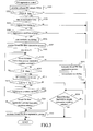
- Fig. 2 is a flow chart of a PM regeneration control routine in a first embodiment.
- Fig. 3 is a flow chart of a PM regeneration control routine in a second embodiment.
- In the following specific embodiments of the exhaust gas purification apparatus for an internal combustion engine according to the present invention will be described with reference to the drawings.
- A first embodiment of the present invention will be described first with reference to Figs. 1 and 2. Fig. 1 is a diagram schematically showing the structure of an internal combustion engine to which the present invention is applied.
- In Fig. 1, the
internal combustion engine 1 is a compression ignition type internal combustion engine that is driven using light oil as fuel (i.e. a diesel engine). Theinternal combustion engine 1 hasmultiple cylinders 2, each of which is equipped with a fuel injection valve 3 that injects fuel directly into thecylinder 2. - The
internal combustion engine 1 is connected with anintake passage 4. A compressor housing 50 of a centrifugal supercharger (i.e. a turbocharger) 5 is provided in theintake passage 4. Anair flow meter 12 is provided in theintake passage 4 upstream of thecompressor housing 50. An intake air cooler (or an intercooler) 6 is provide in theintake passage 4 downstream of thecompressor housing 50. Anintake throttle valve 13 is provided in theintake passage 4 downstream of the intercooler 6. - The
internal combustion engine 1 is also connected with anexhaust passage 7. Aturbine housing 51 of the turbocharger 5 is provided in theexhaust passage 7. Aparticulate filter 8 is provided in theexhaust passage 7 downstream of theturbine housing 51. An oxidation catalyst is supported on the carrier of theparticulate filter 8. - A
fuel addition valve 9 for adding fuel into the exhaust gas flowing through theexhaust passage 7 is provided in theexhaust passage 7 upstream of theturbine housing 51. An exhaustgas temperature sensor 10 is provided in theexhaust passage 7 downstream of theparticulate filter 8. - An
ECU 11 is annexed to theinternal combustion engine 1 having the above described structure. TheECU 11 is an electronic control unit composed of a CPU, a ROM, a RAM and a backup RAM etc.. - The ECU 11 is electrically connected with a
regeneration button 14, anaccelerator position sensor 16 and ashift position sensor 17 in addition to the above mentioned various sensors such as the exhaustgas temperature sensor 10 and theair flow meter 12. - The
regeneration button 14 is a button to be operated by a driver of the vehicle on which theinternal combustion engine 1 is mounted or the operator when activating manual forced PM filter regeneration process. - The ECU 11 is electrically connected with a
notification lamp 18 as well as the fuel injection valve 3, thefuel addition valve 9 and theintake throttle valve 13 etc.. - The
notification lamp 18 is provided near the driver seat of the vehicle, and it is turned on when it is necessary to manually activate the forced PM filter regeneration process on theparticulate filter 8. Thenotification lamp 18 may be constructed as aregeneration button 14 that is adapted to glow. - In the
internal combustion engine 1 having the above described structure, theECU 11 executes a PM filter regeneration control which constitutes the main feature of the present invention as well as known control processes such as fuel injection control etc. - In the PM filter regeneration control, the
ECU 11 firstly calculates the amount of the PM collected on theparticulate filter 8. The method of calculating the amount of the collected PM may be, for example, reducing the pressure difference between upstream and downstream of theparticulate filter 8 to the amount of the collected PM, or determining the amount of the PM discharged from theinternal combustion engine 1 based on the engine load and the number of revolutions of the engine as parameters and integrating that PM amount to obtain the amount of the collected PM. - The ECU 11 makes a determination as to whether or not the amount of the collected PM is not smaller than a predetermined amount. If the amount of the collected PM is not smaller than the predetermined amount, the
ECU 11 turns on thenotification lamp 18 to notify the driver or the operator of the fact that it is necessary to executes the forced PM filter regeneration process on theparticulate filter 8. - If the
regeneration button 14 is operated while thenotification lamp 8 is on and the operating state of theinternal combustion engine 1 and/or the driving state of the vehicle satisfies the condition for performing regeneration, theECU 11 executes the forced PM filter regeneration process. - The condition for performing regeneration may be, for example, the stationary idling state (the vehicle is in a stopping state and the internal combustion engine is in a idling state). Criteria for making a determination as to whether the vehicle is in the stationary idling state may include, for example, whether the number of revolutions of the engine is not higher than a predetermined number of revolutions (for example, about 800 rpm), whether the output signal of the
accelerator position sensor 16 is zero (accelerator opening = 0), and whether the output signal of theshift position sensor 17 indicates a neutral position or a parking position. - The forced PM filter regeneration process may be executed, for example, by decreasing the degree of opening of the
intake throttle valve 13, increasing the fuel injection quantity to increase the idling speed to a predetermined idle-up speed (for example, about 1200 rpm) (idle-up control), and adding fuel into the exhaust gas through thefuel addition valve 9. - When the degree of opening of the
intake throttle valve 13 is made small, the quantity of the intake air entering theinternal combustion engine 1 decreases, and the quantity of the exhaust gas discharged from theinternal combustion engine 1 also decreases accordingly. A decrease in the exhaust gas quantity leads to an increase in the quantity of heat per unit exhaust gas quantity, which in turn leads to an increase in the temperature of the exhaust gas. - When the idle-up control is performed, the quantity of fuel injected through the fuel injection valve 3 increases, and the quantity of heat discharged from the
internal combustion engine 1 increases accordingly. Such an increase in the quantity of heat causes, in combination with a decrease in the exhaust gas quantity caused by theintake throttle valve 13, a further increase in the temperature of the exhaust gas. - When fuel is added into the exhaust gas through the
fuel addition valve 9, the added fuel and the exhaust gas flow into theparticulate filter 8. The added fuel flowing into theparticulate filter 8 is oxidized by the catalyst supported on theparticulate filter 8, and therefore theparticulate filter 8 is heated by the oxidation reaction heat generated thereby. - Therefore, the
particulate filter 8 is heated by a small quantity of high temperature exhaust gas and simultaneously heated by the reaction heat generated upon oxidation of the added fuel. Thus, the temperature of theparticulate filter 8 rises rapidly up into the temperature range in which oxidation of the PM is possible. - As an alternative method of performing the forced PM filter regeneration process, the degree of opening of the exhaust throttle valve may be decreased instead of or simultaneously with decreasing the degree of opening of the
intake throttle valve 13. - As still other method of performing the forced PM filter regeneration process, the timing of fuel injection through the fuel injection valve 3 may be retarded or post injection may be performed through the fuel injection valve 3 instead of or in addition to adding fuel into the exhaust gas through the
fuel addition valve 9. - The above described forced PM filter regeneration process is terminated at the time when a condition for terminating the forced PM filter regeneration process is satisfied. The condition for terminating the forced PM filter regeneration process may be, for example, that the amount of the PM remaining on the
particulate filter 8 is not larger than a predetermined amount (e.g. zero). - The
ECU 11 restricts driving of the vehicle during execution of the forced PM filter regeneration process. Specifically, theECU 11 causes thenotification lamp 18 to keep on glowing or blinking during execution of the forced PM filter regeneration process to invite the driver or the operator to refrain from driving the vehicle. - Instead of turning on the
notification lamp 18, a message to the effect that the driving of the vehicle should be refrained from may be delivered through a display apparatus such as a navigation system or an audio output apparatus such as a loudspeaker. Instead of or in addition to performing an indirect restriction on driving as above, a direct restriction on driving such as shift lock or a restriction of the speed may be effected. - In the meantime, since the timing of operation of the
regeneration button 14 by the driver or the operator varies depending on occasions, the amount of the collected PM at the time the forced PM filter regeneration process is started may be excessively large in some cases. In such cases, it is expected that the execution time of the forced PM filter regeneration process will become excessively long. Especially during stationary idling, the execution time of the forced PM filter regeneration process can be further elongated since the quantity of oxygen supplied to theparticulate filter 8 becomes smaller with a decrease in the flow rate of the exhaust gas flowing into theparticulate filter 8. If the execution time of the forced PM filter regeneration process becomes long, the driver or the operator will be restricted from driving for a long time. - In view of this, the forced PM filter regeneration process may be executed during a time in which the flow rate of the exhaust gas is relatively high, such as while the vehicle is moving. However, if a large amount of oxygen is supplied to the
particulate filter 8 when the amount of the collected PM is relatively large, there is a possibility that a large amount of PM is oxidized all at once to cause an excessive temperature rise of theparticulate filter 8. Therefore, it is difficult to executes the forced PM filter regeneration process at a time other than during stationary idling state. - In view of the above, in this embodiment, the
ECU 11 is adapted to lift the restriction on driving at the time when the execution time of the forced PM filter regeneration process exceeds a predetermined time and to continue the forced PM filter regeneration process. Specifically, when the execution time of the forced PM filter regeneration process exceeds the predetermined time, theECU 11 turns off thenotification lamp 18 and continues the forced PM filter regeneration process as long as the stationary idling state continues. - In the following, a PM filter regeneration control according to this embodiment will be described in detail with reference to Fig. 2. Fig. 2 is a flow chart of a PM regeneration control routine. This PM filter regeneration control routine is a routine that is stored in the ROM of the
ECU 11 in advance, and executed by theECU 11 repeatedly at predetermined regular intervals. - Firstly in step S101 of the PM filter regeneration control routine, the
ECU 11 calculates the amount of the collected PM ΣPM on theparticulate filter 8. - In step S102, the
ECU 11 makes a determination as to whether or not said amount of the collected PM ΣPM calculated in said step S101 is equal to or larger than a predetermined amount Apm. - If it is determined in said step S102 that said collected PM amount ΣPM calculated in said step S101 is smaller than a predetermined amount Apm (ΣPM < Apm), the ECU once terminates execution of this routine.
- If it is determined in said step S102 that said the collected PM amount ΣPM calculated in said step S101 is not smaller than a predetermined amount Apm (ΣPM ≥ Apm), the
ECU 11 advances to step S103, where thenotification lamp 18 is turned on. - In step S104, the
ECU 11 makes a determination as to whether or not theregeneration button 14 is on. If it is determined in this step S104 that theregeneration button 14 is not on, theECU 11 once terminates execution of this routine. - On the other hand, if it is determined in step S104 that the
regeneration button 14 is on, theECU 11 advances to step S105. In step S105, theECU 11 makes a determination as to whether or not the condition for performing regeneration is satisfied. - Specifically, in step S105, the
ECU 11 makes a determination as to whether or not the number of revolutions of the engine is equal to or lower than a predetermined number of revolutions, the output signal of theaccelerator position sensor 16 is zero (i.e. the accelerator opening is zero), and the output signal of theshift position sensor 17 indicates the neutral position or the position for parking. - If the question in said step S105 is answered in the negative, the
ECU 11 once terminates execution of this routine. On the other hand, if the question in said step S105 is answered in the affirmative, the ECU advances to step S106. - In step S 106, the
ECU 11 starts a restriction on driving of the vehicle. In this embodiment, theECU 11 causes thenotification lamp 18 to glow or blink to invite the driver or the operator to refrain from driving the vehicle. - In step S107, the
ECU 11 executes forced PM filter regeneration process. Specifically, theECU 11 decreases the degree of opening of theintake throttle valve 13, increases the fuel injection quantity to raise the idling speed to the idle-up speed, and in addition causes thefuel addition valve 9 to add fuel into the exhaust gas. - In step S108, the
ECU 11 starts a timer T. This timer T is adapted to measure the execution time of the forced PM filter regeneration process. - In step S109, the
ECU 11 makes a determination as to whether or not the condition for terminating the forced PM filter regeneration process is satisfied. Specifically, theECU 11 makes a determination as to whether or not the total amount of the PM oxidized in the particulate filter 8 (the oxidized PM amount) ZOpm is equal to or larger than the collected PM amount ΣPM calculated in step S101. The oxidized PM amount Σopm can be obtained using as parameters the temperature of theparticulate filter 8 and the integrated value of the quantity of the exhaust gas (oxidation quantity) flowing into theparticulate filter 8. - If it is determined in step S109 that the condition for terminating the forced PM filter regeneration process is not satisfied, the
ECU 11 advances to step S110. In step S110, theECU 11 makes a determination as to whether or not the time measured by the timer T is equal to or longer than a predetermined time Tbase (i.e. whether or not the forced PM filter regeneration process has been executed for the predetermined time or longer than the predetermined time). - If it is determined in said step S110 that the time measured by the timer T is shorter than the predetermined time Tbase (T < Tbase), the
ECU 11 executes the process of step S109 and the subsequent steps again. - On the other hand, if it is determined in said step S110 that the time measured by the timer T is not shorter than the predetermined time Tbase (T ≥ Tbase), the
ECU 11 advances to step S111. In step S111, theECU 11 turns off thenotification lamp 18 to lift the restriction on driving of the vehicle. At that time, theECU 11 may return the idling speed to the normal idling speed. This is because if the driver starts to drive the vehicle in the state in which the idling speed is made high, there is a possibility that the startability of the vehicle can be deteriorated. - In step S112, the
ECU 11 makes a determination as to whether or not the condition for performing regeneration is satisfied. If it is determined in this step S112 that the condition for performing regeneration is satisfied, theECU 11 advances to step S113. - In step Sl13, the
ECU 11 makes a determination as to whether or not the condition for terminating the forced PM filter regeneration process is satisfied again. If it is determined in this step S113 that the condition for terminating the forced PM filter regeneration process is not satisfied, theECU 11 executes the process of said step S112 and the subsequent steps again. - On the other hand, if it is determined in step S113 that the condition for terminating the forced PM filter regeneration process is satisfied, the
ECU 11 advances to step S114. In step S114, theECU 11 terminates execution of the forced PM filter regeneration process. Specifically, theECU 11 returns the degree of opening of theintake throttle valve 13 to the normal degree of opening and stops fuel injection through the fuel addition valve 9 (and also stops the idle-up control if the idle-up control is continued). In the case where it is determined in the above mentioned step S112 that the condition for performing regeneration is not satisfied, namely in the case where the vehicle starts to move before the condition for terminating the forced PM filter regeneration process is satisfied, theECU 11 skips step S113 to advance to step S114, where theECU 11 terminates execution of the forced PM filter regeneration process immediately. - If it is determined in the above described step S109 that the condition for terminating the forced PM filter regeneration process is satisfied, namely if the condition for terminating the forced PM filter regeneration process is satisfied before the execution time of the forced PM filter regeneration process reaches the predetermined time Tbase, the
ECU 11 terminates, in step S115, execution of the forced PM filter regeneration process, and turns off, in step S116, thenotification lamp 18 to lift the restriction on driving of the vehicle. - As per the above, by executing the PM regeneration control routine on the
ECU 11, when the execution time of the forced PM filter regeneration process reaches the predetermined time Tbase, the restriction on driving of the vehicle is lifted even if regeneration of theparticulate filter 8 has not been completed. Therefore, the time over which driving is restricted will not become excessively long. - In addition, since the forced PM filter regeneration process is continued after the restriction on driving has been lifted, as long as the condition for performing regeneration is satisfied (namely, as long as the stationary idling state continues), it is possible to suppress a decrease in the efficiency of regeneration to the minimum.
- As per the above, according to this embodiment, in an exhaust gas purification apparatus for an internal combustion engine that places a restriction on driving of the vehicle during execution of the PM filter regeneration process, it is possible to suppress a decrease in the efficiency of regeneration to the minimum while preventing lengthening of the restriction on driving.
- Next, a second embodiment of the exhaust gas purification apparatus for an internal combustion engine according to the present invention will be described with reference to Fig. 3.
- In the above described first embodiment, a case in which the forced PM filter regeneration process is continued after the restriction on driving has been lifted, as long as the condition for performing regeneration is satisfied. In this embodiment, a case in which the forced PM filter regeneration process is continued regardless of whether the condition for performing regeneration is satisfied or not, if the amount of the PM remaining on the
particulate filter 8 is sufficiently small at the time when the restriction on driving is lifted. - If the vehicle is driven freely in the state in which the amount of the PM remaining on the
particulate filter 8 is relatively large, there is a possibility that a large amount of PM is oxidized all at once. For example, if theinternal combustion engine 1 is driven in a decelerated manner and a fuel cut control is performed during execution of the forced PM filter regeneration process, theparticulate filter 8 is exposed to an atmosphere that contains excessive oxygen. If theparticulate filter 8 is exposed to an atmosphere that contains excessive oxygen during execution of the forced PM filter regeneration process, a large amount of the PM remaining on theparticulate filter 8 can be oxidized all at once in some cases. In such cases, the quantity of oxidation heat generated thereby increases steeply, and there is a possibility that the temperature of theparticulate filter 8 rises excessively. - On the other hand, in the case where the amount of the PM remaining on the
particulate filter 8 is relatively small, the temperature of theparticulate filter 8 is hard to rise excessively even if the PM remaining on theparticulate filter 8 is oxidized all at once. - Therefore, by continuing the forced PM filter regeneration process, in the case where the amount of the PM remaining on the
particulate filter 8 at the time when the restriction on driving is lifted is small, until the condition for terminating the forced PM filter regeneration process is satisfied, regardless of whether the condition for performing regeneration is satisfied or not, it is possible to further reduce a decrease in the efficiency of regeneration. - In the following, a PM regeneration control according to this embodiment will be described with reference to Fig. 3. Fig. 3 is a flow chart of the PM regeneration control routine according to this embodiment.
- In the PM regeneration control routine shown in Fig. 3, the process in steps S201 through S211 is the same as that of steps S101 through S111 in the above described first embodiment, and the process of steps S216 and S217 is the same as that in steps S115 and S116 in the above described first embodiment, and descriptions thereof will be omitted.
- In step S212, the
ECU 11 makes a determination as to whether or not the amount of the PM remaining on the particulate filter 8 (which will be referred to as the remaining PM amount) ΔΣPM is smaller than a predetermined amount Bpm. The remaining PM amount ΔΣPM can be obtained by subtracting the oxidized PM amount ΣOpm from the collected PM amount ΣPM. The aforementioned predetermined amount Bpm is such a PM amount with which an excessive temperature rise of theparticulate filter 8 will not occur even if theinternal combustion engine 1 is driven in a decelerated manner while the vehicle is moving. - In this step, the value of the oxidized PM amount ΣOpm used may be the value calculated in step S209 or it may be newly calculated at the time when step S212 is executed.
- If it is determined in step S212 that the remaining PM amount ΔΣPM is not smaller than the predetermined PM amount Bpm (ΔΣPM ≧ Bpm), the
ECU 11 executes the process of steps S213 to S215. The process of steps S213 to S215 is the same as that of steps S112 to S114 in the above described first embodiment, and descriptions thereof will be omitted. - If it is determined in step S212 that the remaining PM amount ΔΣPM is smaller than the predetermined PM amount Bpm (ΔΣPM < Bpm), the
ECU 11 advances to step S218, where theECU 11 continues the forced PM filter regeneration process until the condition for terminating the forced PM filter regeneration process is satisfied. If it is determined in said step S218 that the condition for terminating the forced PM filter regeneration process is satisfied, the ECU 15 advances to step S215 and terminates execution of the forced PM filter regeneration process. TheECU 11 may be adapted to stop the idle-up control at the time when it is determined in said step S212 that the remaining PM amount ΔΣPM is smaller than the predetermined amount Bpm. - In this case, the
ECU 11 will continue the forced PM filter regeneration process until the condition for terminating the forced PM filter regeneration process ends, even if the condition for performing regeneration becomes a failure. - In the PM regeneration control routine shown in Fig. 3, if it is determined in step S214 that the condition for terminating the forced PM filter regeneration process is not satisfied, the process of step S213 and the subsequent steps is executed again. However, the process of steps S212 and the subsequent steps may be executed again. In other words, if the question in said step S214 is answered in the negative, the
ECU 11 may make a determination as to whether or not the remaining PM amount ΔΣPM is smaller than the predetermined amount Bpm again. - In the PM regeneration control routine shown in Fig. 3, if it is determined in step S213 that the condition for performing regeneration is not satisfied, the
ECU 11 is adapted to advance to step S215 to terminate the forced PM filter regeneration process. However, theECU 11 may be adapted not to advance to step S215 but to return to step S212. In other words, if the question in step S213 is answered in the negative, theECU 11 may make a determination as to whether or not the remaining PM amount AZPM is smaller than the predetermined amount Bpm again. - According to the above described embodiment, it is possible to prevent lengthening of the time over which driving is restricted as is the case with the above descried first embodiment, and in addition it is possible to further reduce a decrease in the efficiency of regeneration.
- The description of this embodiment has been directed to a case in which if the remaining PM amount at the time when the restriction on driving is lifted is smaller than a predetermined amount, the forced PM filter regeneration process is continued until the condition for terminating the forced PM filter regeneration process is satisfied. However, the forced PM filter regeneration process may be continued until the condition for terminating the forced PM filter regeneration process is satisfied even in the case where the remaining PM amount becomes smaller than a predetermined amount during the period from the time at which the restriction on driving is lifted until the time at which the condition for performing regeneration becomes a failure and in the case where the remaining PM amount is smaller than a predetermined amount at the time when the condition for performing regeneration becomes a failure.
- Although in this embodiment, the predetermined time Tbase is set to a fixed value, it may be a variable value that is changed in accordance with the collected PM amount ΣPM at the time when execution of the forced PM filter regeneration process is started. In this case, the variable value may be determined in such a way that the remaining PM amount ΔΣPM at the time when the restriction on driving is lifted becomes smaller than the predetermined amount Bpm. If the variable value is determined in this way, the advantageous effect that the efficiency of regeneration hardly decreases is achieved, though there is a possibility that the time over which driving is restricted can be lengthened to some extent as compared to the above described embodiment.
Claims (4)
- An exhaust gas purification apparatus for an internal combustion engine, characterized by:a particulate filter provided in an exhaust passage of an internal combustion engine;regeneration processing means for performing a forced PM filter regeneration process on said particulate filter when the condition of said internal combustion engine and/or a vehicle equipped with said internal combustion engine satisfies a condition for performing regeneration;restriction means for restricting driving of the vehicle equipped with said internal combustion engine when the forced PM filter regeneration process is performed;time measuring means for measuring the time elapsed since the forced PM filter regeneration is started; andregeneration control means for lifting, when the measurement value of said time measuring means exceeds a predetermined time before a condition for terminating the forced PM filter regeneration process is satisfied, a restriction by said restriction means and causing said regeneration processing means to continue the forced PM filter regeneration process.
- An exhaust gas purification apparatus for an internal combustion engine according to claim 1, characterized in that said regeneration control means causes, after lifting the restriction by said restriction means, said regeneration processing means to continue the forced PM filter regeneration process until said condition for performing regeneration becomes a failure or until the condition for terminating the forced PM filter regeneration process is satisfied.
- An exhaust gas purification apparatus for an internal combustion engine according to claim 1, characterized in that if the amount of the PM remaining on said particulate filter is smaller than a predetermined amount at the time when the restriction by said restriction means is lifted , said regeneration control means causes said regeneration processing means to continue the forced PM filter regeneration process until the condition for terminating the forced PM filter regeneration process is satisfied.
- An exhaust gas purification apparatus for an internal combustion engine according to any one of claims 1 to 3, characterized in that if a request for regeneration is manually entered at a time when said condition for performing regeneration is satisfied, said regeneration processing means starts said forced PM filter regeneration process.
Applications Claiming Priority (2)
| Application Number | Priority Date | Filing Date | Title |
|---|---|---|---|
| JP2004271588A JP4193778B2 (en) | 2004-09-17 | 2004-09-17 | Exhaust gas purification device for internal combustion engine |
| PCT/JP2005/017545 WO2006030979A1 (en) | 2004-09-17 | 2005-09-16 | Exhaust emission control device of internal combustion engine |
Publications (3)
| Publication Number | Publication Date |
|---|---|
| EP1801370A1 true EP1801370A1 (en) | 2007-06-27 |
| EP1801370A4 EP1801370A4 (en) | 2007-12-05 |
| EP1801370B1 EP1801370B1 (en) | 2011-11-09 |
Family
ID=36060213
Family Applications (1)
| Application Number | Title | Priority Date | Filing Date |
|---|---|---|---|
| EP05785841A Ceased EP1801370B1 (en) | 2004-09-17 | 2005-09-16 | Exhaust emission control device of internal combustion engine |
Country Status (3)
| Country | Link |
|---|---|
| EP (1) | EP1801370B1 (en) |
| JP (1) | JP4193778B2 (en) |
| WO (1) | WO2006030979A1 (en) |
Cited By (4)
| Publication number | Priority date | Publication date | Assignee | Title |
|---|---|---|---|---|
| WO2009132852A1 (en) * | 2008-04-30 | 2009-11-05 | Perkins Engines Company Limited | Exhaust treatment system implementing regeneration control |
| US8973351B2 (en) | 2011-11-29 | 2015-03-10 | Kubota Corporation | Work machine |
| US10731548B2 (en) | 2017-04-27 | 2020-08-04 | Toyota Jidosha Kabushiki Kaisha | Mechanical supercharging system |
| US11655742B2 (en) | 2021-09-03 | 2023-05-23 | Toyota Jidosha Kabushiki Kaisha | Vehicle control device |
Families Citing this family (6)
| Publication number | Priority date | Publication date | Assignee | Title |
|---|---|---|---|---|
| JP4100449B1 (en) * | 2007-01-26 | 2008-06-11 | いすゞ自動車株式会社 | Exhaust gas purification system control method and exhaust gas purification system |
| JP5863415B2 (en) * | 2011-11-25 | 2016-02-16 | 株式会社クボタ | Working machine |
| JP2013113215A (en) * | 2011-11-29 | 2013-06-10 | Kubota Corp | Work machine |
| JP2014238057A (en) * | 2013-06-07 | 2014-12-18 | ヤンマー株式会社 | Exhaust emission control device |
| WO2015004713A1 (en) * | 2013-07-08 | 2015-01-15 | トヨタ自動車株式会社 | Control method for internal combustion engine |
| JP5856111B2 (en) * | 2013-07-29 | 2016-02-09 | ヤンマー株式会社 | Engine equipment |
Family Cites Families (7)
| Publication number | Priority date | Publication date | Assignee | Title |
|---|---|---|---|---|
| DE3580606D1 (en) | 1984-03-31 | 1991-01-03 | Mitsubishi Motors Corp | REGENERATION SYSTEM FOR A DIESEL PARTICLE OXYDING DEVICE. |
| US4884398A (en) * | 1987-10-19 | 1989-12-05 | Shin Caterpillar Mitsubishi Ltd. | Method of and apparatus for reducing engine smoke emissions |
| JPH04134115A (en) * | 1990-09-27 | 1992-05-08 | Mazda Motor Corp | Exhauster for diesel engine |
| JPH1018834A (en) | 1996-07-02 | 1998-01-20 | Sumitomo Electric Ind Ltd | Method and apparatus for removing particulates from exhaust gas |
| JP2003120259A (en) * | 2001-10-09 | 2003-04-23 | Tadano Ltd | Usage confirmation device for diesel particulate removing device and using method of usage confirmation device for diesel particulate removing device |
| JP4007085B2 (en) | 2002-06-13 | 2007-11-14 | 株式会社デンソー | Exhaust gas purification device for internal combustion engine |
| US6948486B2 (en) * | 2002-06-28 | 2005-09-27 | Fleetguard, Inc. | System and method for derating an engine to encourage servicing of a vehicle |
-
2004
- 2004-09-17 JP JP2004271588A patent/JP4193778B2/en not_active Expired - Fee Related
-
2005
- 2005-09-16 WO PCT/JP2005/017545 patent/WO2006030979A1/en not_active Ceased
- 2005-09-16 EP EP05785841A patent/EP1801370B1/en not_active Ceased
Cited By (6)
| Publication number | Priority date | Publication date | Assignee | Title |
|---|---|---|---|---|
| WO2009132852A1 (en) * | 2008-04-30 | 2009-11-05 | Perkins Engines Company Limited | Exhaust treatment system implementing regeneration control |
| US8322132B2 (en) | 2008-04-30 | 2012-12-04 | Perkins Engines Company Limited | Exhaust treatment system implementing regeneration control |
| US8973351B2 (en) | 2011-11-29 | 2015-03-10 | Kubota Corporation | Work machine |
| US10731548B2 (en) | 2017-04-27 | 2020-08-04 | Toyota Jidosha Kabushiki Kaisha | Mechanical supercharging system |
| EP3396133B1 (en) * | 2017-04-27 | 2021-06-30 | Toyota Jidosha Kabushiki Kaisha | Mechanical supercharging system |
| US11655742B2 (en) | 2021-09-03 | 2023-05-23 | Toyota Jidosha Kabushiki Kaisha | Vehicle control device |
Also Published As
| Publication number | Publication date |
|---|---|
| JP4193778B2 (en) | 2008-12-10 |
| EP1801370A4 (en) | 2007-12-05 |
| EP1801370B1 (en) | 2011-11-09 |
| WO2006030979A1 (en) | 2006-03-23 |
| JP2006083817A (en) | 2006-03-30 |
Similar Documents
| Publication | Publication Date | Title |
|---|---|---|
| KR100829649B1 (en) | Egr control apparatus and method for operating the same | |
| US8397500B2 (en) | System and method for estimating airflow restriction of an engine air filter | |
| JP4103813B2 (en) | Exhaust gas purification device for internal combustion engine | |
| EP1890026B1 (en) | Control device for an internal combustion engine of a vehicle | |
| EP1464808A1 (en) | Control apparatus and control method for internal combustion engine | |
| JP2009191694A (en) | Exhaust gas purification device for internal combustion engine | |
| EP1801370B1 (en) | Exhaust emission control device of internal combustion engine | |
| CA2138563C (en) | Catalyst deterioration-determining device of an internal combustion engine | |
| US10309285B2 (en) | Exhaust gas control system for internal combustion engine | |
| US10302000B2 (en) | Exhaust gas control system for internal combustion engine | |
| JP2005325812A (en) | Filter failure judgment device | |
| EP1553267A1 (en) | Device and method for purifying exhaust gas from industrial vehicle engine | |
| US20130092030A1 (en) | Exhaust gas purifying apparatus for diesel engine | |
| US20050155345A1 (en) | Device and method for purifying exhaust gas from industrial vehicle engine | |
| US11698018B2 (en) | Control device and control method for internal combustion engine | |
| CN100436790C (en) | Fuel cut control system | |
| KR20060002814A (en) | Method for removing particles from exhaust gas of internal combustion engine | |
| WO2008081281A1 (en) | Control system of internal combustion engine | |
| JP3552615B2 (en) | Exhaust gas purification device for internal combustion engine | |
| JP2004285947A (en) | Exhaust purification device for internal combustion engine | |
| US4819601A (en) | Diagnostic system of an air-fuel ratio control device | |
| JPH0435606B2 (en) | ||
| JP4411942B2 (en) | Exhaust gas purification device for internal combustion engine | |
| EP1726807A1 (en) | Engine output control system for internal combustion engine | |
| CN116096987B (en) | Vehicle control device, vehicle, and control method |
Legal Events
| Date | Code | Title | Description |
|---|---|---|---|
| PUAI | Public reference made under article 153(3) epc to a published international application that has entered the european phase |
Free format text: ORIGINAL CODE: 0009012 |
|
| 17P | Request for examination filed |
Effective date: 20060620 |
|
| AK | Designated contracting states |
Kind code of ref document: A1 Designated state(s): DE FR GB |
|
| A4 | Supplementary search report drawn up and despatched |
Effective date: 20071107 |
|
| RIC1 | Information provided on ipc code assigned before grant |
Ipc: F02D 41/02 20060101ALI20071031BHEP Ipc: B01D 53/94 20060101ALI20071031BHEP Ipc: F01N 3/02 20060101AFI20060911BHEP Ipc: B01D 46/42 20060101ALI20071031BHEP |
|
| DAX | Request for extension of the european patent (deleted) | ||
| RBV | Designated contracting states (corrected) |
Designated state(s): DE FR GB |
|
| GRAP | Despatch of communication of intention to grant a patent |
Free format text: ORIGINAL CODE: EPIDOSNIGR1 |
|
| GRAS | Grant fee paid |
Free format text: ORIGINAL CODE: EPIDOSNIGR3 |
|
| GRAA | (expected) grant |
Free format text: ORIGINAL CODE: 0009210 |
|
| AK | Designated contracting states |
Kind code of ref document: B1 Designated state(s): DE FR GB |
|
| REG | Reference to a national code |
Ref country code: GB Ref legal event code: FG4D |
|
| RIN1 | Information on inventor provided before grant (corrected) |
Inventor name: HASHIZUME, TAKESHI, |
|
| REG | Reference to a national code |
Ref country code: DE Ref legal event code: R096 Ref document number: 602005031135 Country of ref document: DE Effective date: 20120105 |
|
| PLBE | No opposition filed within time limit |
Free format text: ORIGINAL CODE: 0009261 |
|
| STAA | Information on the status of an ep patent application or granted ep patent |
Free format text: STATUS: NO OPPOSITION FILED WITHIN TIME LIMIT |
|
| 26N | No opposition filed |
Effective date: 20120810 |
|
| REG | Reference to a national code |
Ref country code: DE Ref legal event code: R097 Ref document number: 602005031135 Country of ref document: DE Effective date: 20120810 |
|
| REG | Reference to a national code |
Ref country code: GB Ref legal event code: 746 Effective date: 20130624 |
|
| REG | Reference to a national code |
Ref country code: DE Ref legal event code: R084 Ref document number: 602005031135 Country of ref document: DE Effective date: 20130614 |
|
| REG | Reference to a national code |
Ref country code: FR Ref legal event code: PLFP Year of fee payment: 12 |
|
| REG | Reference to a national code |
Ref country code: FR Ref legal event code: PLFP Year of fee payment: 13 |
|
| PGFP | Annual fee paid to national office [announced via postgrant information from national office to epo] |
Ref country code: FR Payment date: 20170810 Year of fee payment: 13 Ref country code: DE Payment date: 20170912 Year of fee payment: 13 Ref country code: GB Payment date: 20170913 Year of fee payment: 13 |
|
| REG | Reference to a national code |
Ref country code: DE Ref legal event code: R119 Ref document number: 602005031135 Country of ref document: DE |
|
| GBPC | Gb: european patent ceased through non-payment of renewal fee |
Effective date: 20180916 |
|
| PG25 | Lapsed in a contracting state [announced via postgrant information from national office to epo] |
Ref country code: DE Free format text: LAPSE BECAUSE OF NON-PAYMENT OF DUE FEES Effective date: 20190402 |
|
| PG25 | Lapsed in a contracting state [announced via postgrant information from national office to epo] |
Ref country code: FR Free format text: LAPSE BECAUSE OF NON-PAYMENT OF DUE FEES Effective date: 20180930 |
|
| PG25 | Lapsed in a contracting state [announced via postgrant information from national office to epo] |
Ref country code: GB Free format text: LAPSE BECAUSE OF NON-PAYMENT OF DUE FEES Effective date: 20180916 |