EP1801356B1 - Brennkammer-Turbinen-Übergang - Google Patents
Brennkammer-Turbinen-Übergang Download PDFInfo
- Publication number
- EP1801356B1 EP1801356B1 EP06256373.9A EP06256373A EP1801356B1 EP 1801356 B1 EP1801356 B1 EP 1801356B1 EP 06256373 A EP06256373 A EP 06256373A EP 1801356 B1 EP1801356 B1 EP 1801356B1
- Authority
- EP
- European Patent Office
- Prior art keywords
- assembly
- combustor
- aft
- fixed vane
- lip
- Prior art date
- Legal status (The legal status is an assumption and is not a legal conclusion. Google has not performed a legal analysis and makes no representation as to the accuracy of the status listed.)
- Expired - Fee Related
Links
Images


Classifications
-
- F—MECHANICAL ENGINEERING; LIGHTING; HEATING; WEAPONS; BLASTING
- F01—MACHINES OR ENGINES IN GENERAL; ENGINE PLANTS IN GENERAL; STEAM ENGINES
- F01D—NON-POSITIVE DISPLACEMENT MACHINES OR ENGINES, e.g. STEAM TURBINES
- F01D9/00—Stators
- F01D9/02—Nozzles; Nozzle boxes; Stator blades; Guide conduits, e.g. individual nozzles
- F01D9/023—Transition ducts between combustor cans and first stage of the turbine in gas-turbine engines; their cooling or sealings
-
- F—MECHANICAL ENGINEERING; LIGHTING; HEATING; WEAPONS; BLASTING
- F23—COMBUSTION APPARATUS; COMBUSTION PROCESSES
- F23R—GENERATING COMBUSTION PRODUCTS OF HIGH PRESSURE OR HIGH VELOCITY, e.g. GAS-TURBINE COMBUSTION CHAMBERS
- F23R3/00—Continuous combustion chambers using liquid or gaseous fuel
- F23R3/42—Continuous combustion chambers using liquid or gaseous fuel characterised by the arrangement or form of the flame tubes or combustion chambers
- F23R3/50—Combustion chambers comprising an annular flame tube within an annular casing
-
- F—MECHANICAL ENGINEERING; LIGHTING; HEATING; WEAPONS; BLASTING
- F05—INDEXING SCHEMES RELATING TO ENGINES OR PUMPS IN VARIOUS SUBCLASSES OF CLASSES F01-F04
- F05D—INDEXING SCHEME FOR ASPECTS RELATING TO NON-POSITIVE-DISPLACEMENT MACHINES OR ENGINES, GAS-TURBINES OR JET-PROPULSION PLANTS
- F05D2240/00—Components
- F05D2240/35—Combustors or associated equipment
Definitions
- This invention relates generally to a combustor assembly for a gas turbine engine. More particularly, this invention relates to an interface between a combustor assembly and a fixed turbine vane portion of a gas turbine engine.
- a gas turbine engine typically includes a combustor for igniting a mixture of fuel and compressed air to produce a gas flow.
- the combustor typically includes an outer shell supporting a plurality of inner heat shields. The inner heat shields are exposed to elevated temperatures produced by ignition of the fuel-air mixture and the resulting gas flow.
- Gas flow exiting the combustor enters a fixed array of turbine vanes that directs gas flow to downstream rotating turbine blades.
- the fixed vanes are intermediate the combustor and the rotating turbine blades.
- the support shell and heat shield articles at the aft end of the combustor module terminate at a common axial position or plane upstream of the fixed vanes.
- a prior art combustor assembly having the features of the preamble of claim 1, is shown in US-4567730 .
- Other combustor assemblies are shown in US-5480162 , EP-0321320 , US-6314716 , DE-19733868 , EP-1270874 , US-2004/211188 , EP-1433924 and EP-1148300 .
- An example combustor assembly for a turbine engine includes a combustor liner assembly incorporating a heat shield article having an aft segment or lip corresponding to a fixed vane portion of the turbine assembly that provides a desirable interface between the combustor assembly and the fixed vane portion.
- the example combustor assembly includes a combustor liner assembly incorporating a heat shield article having an aft segment or lip corresponding to a fixed vane portion of a turbine assembly to form a smooth interface for gas flow.
- the aft segment or lip extends an axial distance greater than the remainder of the combustor assembly (and underlying shell) into the endwall region of the downstream fixed vane.
- the fixed vane endwall includes a landing that receives the aft lip such that the portions of the lip and endwall exposed to the core flow provide a smooth curvature in moving axially.
- the smooth axial profile provided by the lip and landing provide the desired aerodynamic properties for the cooling and gas flow at the transition between the combustor and the turbine endwalls.
- the geometry of the landing is configured to tailor cooling patterns and limited unwanted cooling air leakage in this region.
- a combustor assembly provides for the smooth transition of cooling and core flow gas streams from the combustor assembly through the fixed vanes and into the downstream turbine hardware.
- an engine assembly 10 includes a fan (not shown), a compressor 12 that supplies compressed air to a combustor assembly 14. Combustion gasses generated within the combustor assembly 14 flows into a turbine assembly 16.
- the gas turbine engine assembly 10 is shown schematically and illustrates an annular combustor although it is within the contemplation of this invention for application in other known combustor assembly configurations.
- the combustor assembly 14 is disposed annularly about an axis 30 and includes an axial length 50.
- the combustor assembly 14 is secured within an inner (diffuser) case wall 52 and an outer (diffuser) case wall 54, each annularly disposed about the axis 30.
- the combustor assembly features a liner assembly 15 that is supported within the inner case wall 52 and outer case wall 54.
- the liner assembly 15 includes an outer shell 26 supporting a plurality of inner heat shields 28 that define an inner surface 42 of a combustor chamber 20.
- a passage 32 for cooling air is disposed between the outer shell 26 and the inner heat shields 28.
- the combustor chamber 20 includes a forward portion or bulkhead assembly 22 that includes a fuel injector 25 and other opening for supplying fuel and air into the combustion chamber 20 to begin combustion.
- the heat shields 28 are disposed in several segments about the outer shell 26 and combine to protect and thermally isolate the hot gases produced within the combustion chamber 20 from outer features of the combustor assembly 14.
- the combustor chamber 20 is disposed about a centerline 44 disposed annularly about the axis 30.
- the combustor chamber 20 includes an aft open end 24 for directing gas flow 35 to a fixed vane cascade array 18 and the downstream stages of the turbine assembly 16.
- the first fixed vanes 18 include base portions 19 that support an airfoil 21 proximate the aft open end 24 of the combustor chamber 20.
- the base portions 19 are affixed to the end of the combustor assembly 14 or cases as part of the engine assembly, with a transition region between the combustor assembly 14 and the turbine assembly 16.
- the inner heat shields 28 disposed at the aft open end 24 include an aft segment or lip 36.
- the aft lip 36 extends past the axial length 50 of the combustor assembly 14 and into the fixed vane portion 18.
- the aft lip 36 overlaps a portion of the base portions 19 and provides a desired smooth interface for cooling air and gas flow 35 from the combustor chamber 20 into the vane passage 18 and remaining turbine assembly 16.
- the aft open-end 24 interfaces with the fixed vane portion 18 to define the transition region for gas flow 35 to the turbine assembly 16.
- Hot combustion gases flow 35 inside the combustion chamber and are exposed to the hot-side surface 42 of the inner heat shields 28.
- a buffer layer of cooling airflow is directed adjacent the hot side surface 42 of the inner heat shields 28. Interruptions or discontinuities in the hot side surface 42 can potentially cause adverse disturbances in the cooling and gas flows 35.
- the transition between the aft open end 24 of the combustor chamber 20 and the fixed vane portion 18 is substantially uninterrupted due to the aft lip 36 extending axially into the fixed vane 18 and the smooth curvature provided herein.
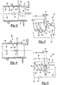
- FIG. 3 an enlarged view of interface 56 between the aft lip of the combustor heat shield 36 and the fixed vane endwall 18 is shown.
- the aft lip 36 extends an axial distance 37 past the length 50 of the combustor assembly 14.
- the fixed vane 18 includes a landing 40 for receiving the aft lip 36.
- the hot side surface 42 of the inner heat shield 28 corresponds with an inner surface 45 of the fixed vane endwall 18 to provide a smooth transition through the interface 56. The smooth transition is provided by the hot side surface 42 being disposed flush with the inner surface 45.
- the hot side surface 42 may also be disposed radially inwardly toward the centerline 44 or transversely vary in shape relative to the inner surface 45 to accommodate or match curvature in the downstream endwall.
- the flush, radially inward or transverse relationship between the hot side surface 42 and the inner surface 45 substantially eliminates features normal and/or transverse to gas flow 35 about the interface 56. The elimination of these features substantially reduces potential disturbances in the cooling air and gas flow 35 through the interface 56.
- the example heat shield 28 includes a plurality of cooling openings 46 through which cooling air 48 flows to create a layer of cooling air along the hot side surface 42.
- the cooling openings 46 are disposed within the heat shield 28 to an aft most end of the combustor chamber 20. Such a configuration provides cooling airflow 48 into the interface 56.
- the example heat shield 28 includes a support feature 29 abutting the outer shell 26 substantially adjacent the aft portion of the combustion chamber 20.
- the support feature 29 supports the aft portion and specifically of the aft lip 36 of the inner heat shield 28.
- the aft lip 36 extends into the landing 40 of the fixed vane portion 18 the axial distance 37.
- the axial distance 37 is between preferentially between 0.10 and 1.0 inches (2.54 - 25.4mm) and, more preferentially between 0.20 and 0.50 inches (5.08 - 12.7 mm).
- the specific axial distance is determined in accordance with desired sealing requirements, and with respect to desired tolerances and clearances required to accommodate manufacturing tolerances and thermal expansion of the combustor assembly 14 and the fixed vane 18.
- the aft lip 36 generally follows the axial and radial circumferential contour of the interface 56 between the liner assembly and the fixed vane portion 18 and may include additional contours to provide a desired streamline transition through the fixed vane portion 18.
- an example combustor liner assembly 60 includes an aft lip 68 that is a portion of an inner heat shield 62.
- the inner heat shield 62 defines the inner surface 66 of the combustor chamber, directing the gas flow 35 out of the combustor chamber 20 and into the fixed vane portion 18.
- the aft lip 68 extends an axial distance 72 into the fixed vane portion 18.
- the fixed vane portion 18 includes a landing 70 that is disposed and configured to receive the aft lip 68.
- the overlapping features may also extend radially and circumferentially about the arcuate shape of the heat shield and turbine endwall and the interface 56 between the liner assembly 15 and the first fixed vane portion 18.
- the aft lip 68 extends into the first fixed vane portion 18 and is supported at least partially by the landing 70.
- the aft portion of the heat shield 68 is not supported at the aft most end of the outer shell 64.
- the aft most support structure for the heat shield 68 is disposed upstream of or near the aft open end 24 such that cooling air 48 is free to be communicated to the furthest aft portions of the aft lip 68. Communication of cooling air 48 is facilitated by a cooling opening(s) 46 that is disposed past the axial length 50 of the combustor assembly 14 within the axial distance 72.
- the communication of cooling air to the furthest aft portion provides design flexibility and may improve the uniformity and effective axial distance into which cooling can introduced into the fixed vane portion 18.
- Such cooling capability can provide increases in cooling flow effectiveness improves durability within the interface 56 by improving temperature uniformity and heat transfer capability through the transition region to the turbine assembly 16 and design flexibility to effectively manage cooling budgets and/or unwanted leakage.
- cooling airflow 48 acts as the effective inner surface or boundary for the gas flow 35. Increasing the effective axial length of the cooling air boundary airflow 48 improves the transitional aerodynamic properties of the gas flow. This is accomplished by substantially eliminating abrupt changes in boundary airflow with regard to the gas flow 35.
- the aft lip 68 includes the cooling openings 46 that are angled relative to the inner surface 66.
- a landing 71 includes a tailored geometric shape that supports the heat shield 62 and cooperates with the geometric shape of the landing 71 to aid in the tailoring of cooling airflow 48.
- the landing 71 includes an angled surface that operates to aid and direct cooling airflow through the cooling openings 46 adjacent extreme ends of the heat shield 62.
- another interface 75 between an aft lip 92 of a single wall liner 76 includes a brace 78 supporting the aft lip 92. Further the brace 78 includes an opening 80 for cooling air such that cooling air 48 is communicated into the interface 75 between the fixed airfoil 21 and the liner 76.
- the liner 76 includes an inner surface 88 having the plurality of cooling air openings 84.
- the aft lip 92 abuts and is supported on a landing 90 of the base portion 19.
- the brace 78 further supports the aft lip 92 and provides the cavity 82 for communication of cooling air 48 to the inner surface 88.
- an example combustor assembly includes features corresponding with a fixed vane portion to smooth the aeromechanical transition between the combustor and the turbine assembly. Further, application of this invention promotes enhanced and cooling flow and leakage management through the integrated combustor-turbine design and decreased discontinuities within the transition region of the combustor assembly and the fixed vane portion 18.
Claims (4)
- Brennkammerbaugruppe (14) für eine Gasturbinentriebwerks-Baugruppe, umfassend:eine Auskleidungsbaugruppe mit einer ein inneres Hitzeschild (28;62;76) stützenden äußeren Schale (26;64), wobei die Auskleidungsbaugruppe eine ringförmige Brennkammer (20) mit einem vorderen Ende (22) und einem offenen hinteren Ende (24) definiert; undeinen fixierten Propellerflügelabschnitt (18), um Gasstrom von der Brennkammer (20) zu einer Turbinenbaugruppe (16) zu leiten, wobei das innere Hitzeschild (28;62;76) einen hinteren Rand (36;68;92) umfasst, der einen Stirnwandbereich des fixierten Propellerflügelabschnitts (18) um einen axialen Abstand (72) überdeckt;dadurch gekennzeichnet, dass:der Stirnwandbereich des fixierten Propellerflügelabschnitts einen Absatz (70;71 ;90) zur Aufnahme des hinteren Randes (36;68;92) aufweist;die Innenfläche (42) des inneren Hitzeschildes (28;62;76) mit einer Innenfläche (45) des Stirnwandbereichs des fixierten Propellerflügelabschnitts verbunden ist, um einen glatten Übergang dazwischen bereitzustellen; undder hintere Rand (36;68;92) innerhalb des axialen Abstandes (72) wenigstens eine Kühlöffnung (46;84) aufweist.
- Baugruppe nach Anspruch 1, wobei das innere Hitzeschild (28;62;76) eine Vielzahl an Hitzeschildern umfasst.
- Baugruppe nach Anspruch 2, wobei jede der Vielzahl von Hitzeschildern (28;62;76) den hinteren Rand (36;68;92) aufweist.
- Baugruppe nach einem der Ansprüche 1 bis 3, wobei der fixierte Stirnwandbereich eine Innenfläche (45) aufweist, die sich in einem radialen Abstand von einer Mittellinie (44) der Brennkammerbaugruppe (14) gleich oder größer eines radialen Abstandes von der Mittellinie einer Innenfläche des hinteren Randes (36;68;92) befindet.
Applications Claiming Priority (1)
| Application Number | Priority Date | Filing Date | Title |
|---|---|---|---|
| US11/315,838 US7934382B2 (en) | 2005-12-22 | 2005-12-22 | Combustor turbine interface |
Publications (3)
| Publication Number | Publication Date |
|---|---|
| EP1801356A2 EP1801356A2 (de) | 2007-06-27 |
| EP1801356A3 EP1801356A3 (de) | 2011-01-26 |
| EP1801356B1 true EP1801356B1 (de) | 2016-03-30 |
Family
ID=37888129
Family Applications (1)
| Application Number | Title | Priority Date | Filing Date |
|---|---|---|---|
| EP06256373.9A Expired - Fee Related EP1801356B1 (de) | 2005-12-22 | 2006-12-14 | Brennkammer-Turbinen-Übergang |
Country Status (5)
| Country | Link |
|---|---|
| US (1) | US7934382B2 (de) |
| EP (1) | EP1801356B1 (de) |
| JP (1) | JP2007170810A (de) |
| IL (1) | IL180207A0 (de) |
| RU (1) | RU2006145714A (de) |
Families Citing this family (18)
| Publication number | Priority date | Publication date | Assignee | Title |
|---|---|---|---|---|
| EP2249003B1 (de) * | 2008-02-27 | 2016-11-02 | Mitsubishi Hitachi Power Systems, Ltd. | Gasturbine |
| US8695322B2 (en) * | 2009-03-30 | 2014-04-15 | General Electric Company | Thermally decoupled can-annular transition piece |
| US9650903B2 (en) * | 2009-08-28 | 2017-05-16 | United Technologies Corporation | Combustor turbine interface for a gas turbine engine |
| US20110185739A1 (en) * | 2010-01-29 | 2011-08-04 | Honeywell International Inc. | Gas turbine combustors with dual walled liners |
| US9057523B2 (en) | 2011-07-29 | 2015-06-16 | United Technologies Corporation | Microcircuit cooling for gas turbine engine combustor |
| JP6013288B2 (ja) * | 2012-07-20 | 2016-10-25 | 株式会社東芝 | タービン、及び発電システム |
| US10167779B2 (en) * | 2012-09-28 | 2019-01-01 | United Technologies Corporation | Mid-turbine frame heat shield |
| EP3033574B1 (de) | 2013-08-16 | 2020-04-29 | United Technologies Corporation | Schottanordnung für gasturbinenbrennkammer und verfahren zur kühlung der schottanordnung |
| WO2015054115A1 (en) | 2013-10-07 | 2015-04-16 | United Technologies Corporation | Combustor wall with tapered cooling cavity |
| US9709279B2 (en) | 2014-02-27 | 2017-07-18 | General Electric Company | System and method for control of combustion dynamics in combustion system |
| US10100675B2 (en) * | 2014-12-09 | 2018-10-16 | United Technologies Corporation | Outer diffuser case for a gas turbine engine |
| GB201518345D0 (en) * | 2015-10-16 | 2015-12-02 | Rolls Royce | Combustor for a gas turbine engine |
| DE102016116222A1 (de) * | 2016-08-31 | 2018-03-01 | Rolls-Royce Deutschland Ltd & Co Kg | Gasturbine |
| US10378770B2 (en) | 2017-01-27 | 2019-08-13 | General Electric Company | Unitary flow path structure |
| US10393381B2 (en) | 2017-01-27 | 2019-08-27 | General Electric Company | Unitary flow path structure |
| US10247019B2 (en) | 2017-02-23 | 2019-04-02 | General Electric Company | Methods and features for positioning a flow path inner boundary within a flow path assembly |
| FR3084141B1 (fr) * | 2018-07-19 | 2021-04-02 | Safran Aircraft Engines | Ensemble pour une turbomachine |
| US11428160B2 (en) | 2020-12-31 | 2022-08-30 | General Electric Company | Gas turbine engine with interdigitated turbine and gear assembly |
Family Cites Families (24)
| Publication number | Priority date | Publication date | Assignee | Title |
|---|---|---|---|---|
| US4567730A (en) * | 1983-10-03 | 1986-02-04 | General Electric Company | Shielded combustor |
| FR2624953B1 (fr) * | 1987-12-16 | 1990-04-20 | Snecma | Chambre de combustion, pour turbomachines, possedant un convergent a doubles parois |
| US5101620A (en) * | 1988-12-28 | 1992-04-07 | Sundstrand Corporation | Annular combustor for a turbine engine without film cooling |
| DE59010740D1 (de) * | 1990-12-05 | 1997-09-04 | Asea Brown Boveri | Gasturbinen-Brennkammer |
| US5435139A (en) * | 1991-03-22 | 1995-07-25 | Rolls-Royce Plc | Removable combustor liner for gas turbine engine combustor |
| US5252026A (en) * | 1993-01-12 | 1993-10-12 | General Electric Company | Gas turbine engine nozzle |
| US5291732A (en) * | 1993-02-08 | 1994-03-08 | General Electric Company | Combustor liner support assembly |
| GB9304994D0 (en) * | 1993-03-11 | 1993-04-28 | Rolls Royce Plc | Improvements in or relating to gas turbine engines |
| GB9305010D0 (en) * | 1993-03-11 | 1993-04-28 | Rolls Royce Plc | A cooled turbine nozzle assembly and a method of calculating the diameters of cooling holes for use in such an assembly |
| US5480162A (en) * | 1993-09-08 | 1996-01-02 | United Technologies Corporation | Axial load carrying brush seal |
| US5628193A (en) * | 1994-09-16 | 1997-05-13 | Alliedsignal Inc. | Combustor-to-turbine transition assembly |
| US5758503A (en) * | 1995-05-03 | 1998-06-02 | United Technologies Corporation | Gas turbine combustor |
| US5758504A (en) | 1996-08-05 | 1998-06-02 | Solar Turbines Incorporated | Impingement/effusion cooled combustor liner |
| US6314716B1 (en) * | 1998-12-18 | 2001-11-13 | Solar Turbines Incorporated | Serial cooling of a combustor for a gas turbine engine |
| US6269628B1 (en) * | 1999-06-10 | 2001-08-07 | Pratt & Whitney Canada Corp. | Apparatus for reducing combustor exit duct cooling |
| JP3478531B2 (ja) | 2000-04-21 | 2003-12-15 | 川崎重工業株式会社 | ガスタービンのセラミック部品支持構造 |
| US6606861B2 (en) * | 2001-02-26 | 2003-08-19 | United Technologies Corporation | Low emissions combustor for a gas turbine engine |
| EP1270874B1 (de) | 2001-06-18 | 2005-08-31 | Siemens Aktiengesellschaft | Gasturbine mit einem Verdichter für Luft |
| JP3951909B2 (ja) | 2002-12-12 | 2007-08-01 | 株式会社日立製作所 | ガスタービン燃焼器 |
| US6860108B2 (en) * | 2003-01-22 | 2005-03-01 | Mitsubishi Heavy Industries, Ltd. | Gas turbine tail tube seal and gas turbine using the same |
| US6964170B2 (en) * | 2003-04-28 | 2005-11-15 | Pratt & Whitney Canada Corp. | Noise reducing combustor |
| US7000406B2 (en) * | 2003-12-03 | 2006-02-21 | Pratt & Whitney Canada Corp. | Gas turbine combustor sliding joint |
| FR2871845B1 (fr) * | 2004-06-17 | 2009-06-26 | Snecma Moteurs Sa | Montage de chambre de combustion de turbine a gaz avec distributeur integre de turbine haute pression |
| US7614235B2 (en) * | 2005-03-01 | 2009-11-10 | United Technologies Corporation | Combustor cooling hole pattern |
-
2005
- 2005-12-22 US US11/315,838 patent/US7934382B2/en not_active Expired - Fee Related
-
2006
- 2006-12-14 EP EP06256373.9A patent/EP1801356B1/de not_active Expired - Fee Related
- 2006-12-15 JP JP2006337980A patent/JP2007170810A/ja active Pending
- 2006-12-20 IL IL180207A patent/IL180207A0/en unknown
- 2006-12-22 RU RU2006145714/06A patent/RU2006145714A/ru not_active Application Discontinuation
Also Published As
| Publication number | Publication date |
|---|---|
| EP1801356A3 (de) | 2011-01-26 |
| EP1801356A2 (de) | 2007-06-27 |
| US20070144177A1 (en) | 2007-06-28 |
| RU2006145714A (ru) | 2008-06-27 |
| US7934382B2 (en) | 2011-05-03 |
| IL180207A0 (en) | 2007-10-31 |
| JP2007170810A (ja) | 2007-07-05 |
Similar Documents
| Publication | Publication Date | Title |
|---|---|---|
| EP1801356B1 (de) | Brennkammer-Turbinen-Übergang | |
| US8726631B2 (en) | Dual walled combustors with impingement cooled igniters | |
| US9377198B2 (en) | Heat shield for a combustor | |
| EP3026343B1 (de) | Selbstkühlende düsenstruktur | |
| US20180238545A1 (en) | Combustor liner panel end rail angled cooling interface passage for a gas turbine engine combustor | |
| US10386070B2 (en) | Multi-streamed dilution hole configuration for a gas turbine engine | |
| EP2904253B1 (de) | Brennkammer mit einer tülle mit einer schutzlippe | |
| EP3361158B1 (de) | Brennkammer für eine gasturbine | |
| US10443848B2 (en) | Grommet assembly and method of design | |
| US9810430B2 (en) | Conjoined grommet assembly for a combustor | |
| EP2971973B1 (de) | Brennkammerplatte und brennkammer mit hitzeschild mit erhöhter beständigkeit | |
| US10724740B2 (en) | Fuel nozzle assembly with impingement purge | |
| US20240093870A1 (en) | Cmc stepped combustor liner | |
| EP3321587B1 (de) | Axiale nichtlineare kontaktfläche für brennkammerverkleidungsplatten in einer gasturbinenbrennkammer | |
| EP3321585B1 (de) | Nichtplanare brennkammerverkleidungsplatte für eine gasturbinenmotorbrennkammer | |
| EP2045527B1 (de) | Facettierte Kuppelanordnungen für Gasturbinen-Verbrennungsmotoren | |
| US10935236B2 (en) | Non-planar combustor liner panel for a gas turbine engine combustor | |
| US6351941B1 (en) | Methods and apparatus for reducing thermal stresses in an augmentor | |
| US20200318549A1 (en) | Non-axisymmetric combustor for improved durability | |
| EP3321588B1 (de) | Gasturbinenbrennkammer |
Legal Events
| Date | Code | Title | Description |
|---|---|---|---|
| PUAI | Public reference made under article 153(3) epc to a published international application that has entered the european phase |
Free format text: ORIGINAL CODE: 0009012 |
|
| AK | Designated contracting states |
Kind code of ref document: A2 Designated state(s): AT BE BG CH CY CZ DE DK EE ES FI FR GB GR HU IE IS IT LI LT LU LV MC NL PL PT RO SE SI SK TR |
|
| AX | Request for extension of the european patent |
Extension state: AL BA HR MK YU |
|
| PUAL | Search report despatched |
Free format text: ORIGINAL CODE: 0009013 |
|
| AK | Designated contracting states |
Kind code of ref document: A3 Designated state(s): AT BE BG CH CY CZ DE DK EE ES FI FR GB GR HU IE IS IT LI LT LU LV MC NL PL PT RO SE SI SK TR |
|
| AX | Request for extension of the european patent |
Extension state: AL BA HR MK RS |
|
| 17P | Request for examination filed |
Effective date: 20110720 |
|
| AKX | Designation fees paid |
Designated state(s): DE GB |
|
| 17Q | First examination report despatched |
Effective date: 20140210 |
|
| GRAP | Despatch of communication of intention to grant a patent |
Free format text: ORIGINAL CODE: EPIDOSNIGR1 |
|
| INTG | Intention to grant announced |
Effective date: 20150928 |
|
| GRAS | Grant fee paid |
Free format text: ORIGINAL CODE: EPIDOSNIGR3 |
|
| GRAA | (expected) grant |
Free format text: ORIGINAL CODE: 0009210 |
|
| AK | Designated contracting states |
Kind code of ref document: B1 Designated state(s): DE GB |
|
| REG | Reference to a national code |
Ref country code: GB Ref legal event code: FG4D |
|
| REG | Reference to a national code |
Ref country code: DE Ref legal event code: R081 Ref document number: 602006048419 Country of ref document: DE Owner name: UNITED TECHNOLOGIES CORP. (N.D.GES.D. STAATES , US Free format text: FORMER OWNER: UNITED TECHNOLOGIES CORP. (N.D.GES.D. STAATES DELAWARE), HARTFORD, CONN., US |
|
| REG | Reference to a national code |
Ref country code: DE Ref legal event code: R096 Ref document number: 602006048419 Country of ref document: DE |
|
| RAP2 | Party data changed (patent owner data changed or rights of a patent transferred) |
Owner name: UNITED TECHNOLOGIES CORPORATION |
|
| REG | Reference to a national code |
Ref country code: DE Ref legal event code: R097 Ref document number: 602006048419 Country of ref document: DE |
|
| PLBE | No opposition filed within time limit |
Free format text: ORIGINAL CODE: 0009261 |
|
| STAA | Information on the status of an ep patent application or granted ep patent |
Free format text: STATUS: NO OPPOSITION FILED WITHIN TIME LIMIT |
|
| 26N | No opposition filed |
Effective date: 20170103 |
|
| REG | Reference to a national code |
Ref country code: DE Ref legal event code: R082 Ref document number: 602006048419 Country of ref document: DE Representative=s name: SCHMITT-NILSON SCHRAUD WAIBEL WOHLFROM PATENTA, DE |
|
| REG | Reference to a national code |
Ref country code: DE Ref legal event code: R082 Ref document number: 602006048419 Country of ref document: DE Representative=s name: SCHMITT-NILSON SCHRAUD WAIBEL WOHLFROM PATENTA, DE Ref country code: DE Ref legal event code: R081 Ref document number: 602006048419 Country of ref document: DE Owner name: UNITED TECHNOLOGIES CORP. (N.D.GES.D. STAATES , US Free format text: FORMER OWNER: UNITED TECHNOLOGIES CORPORATION, HARTFORD, CONN., US |
|
| PGFP | Annual fee paid to national office [announced via postgrant information from national office to epo] |
Ref country code: DE Payment date: 20191119 Year of fee payment: 14 |
|
| REG | Reference to a national code |
Ref country code: DE Ref legal event code: R119 Ref document number: 602006048419 Country of ref document: DE |
|
| PG25 | Lapsed in a contracting state [announced via postgrant information from national office to epo] |
Ref country code: DE Free format text: LAPSE BECAUSE OF NON-PAYMENT OF DUE FEES Effective date: 20210701 |
|
| PGFP | Annual fee paid to national office [announced via postgrant information from national office to epo] |
Ref country code: GB Payment date: 20211118 Year of fee payment: 16 |
|
| GBPC | Gb: european patent ceased through non-payment of renewal fee |
Effective date: 20221214 |
|
| PG25 | Lapsed in a contracting state [announced via postgrant information from national office to epo] |
Ref country code: GB Free format text: LAPSE BECAUSE OF NON-PAYMENT OF DUE FEES Effective date: 20221214 |