EP1801349B1 - High pressure turbine disk hub with reduced axial stress and method - Google Patents
High pressure turbine disk hub with reduced axial stress and method Download PDFInfo
- Publication number
- EP1801349B1 EP1801349B1 EP06126554.2A EP06126554A EP1801349B1 EP 1801349 B1 EP1801349 B1 EP 1801349B1 EP 06126554 A EP06126554 A EP 06126554A EP 1801349 B1 EP1801349 B1 EP 1801349B1
- Authority
- EP
- European Patent Office
- Prior art keywords
- hub
- disk
- radially
- disk hub
- annular
- Prior art date
- Legal status (The legal status is an assumption and is not a legal conclusion. Google has not performed a legal analysis and makes no representation as to the accuracy of the status listed.)
- Not-in-force
Links
- 238000000034 method Methods 0.000 title claims description 5
- 239000007789 gas Substances 0.000 claims description 13
- 230000000116 mitigating effect Effects 0.000 claims description 3
- 230000015572 biosynthetic process Effects 0.000 claims description 2
- 230000009467 reduction Effects 0.000 description 5
- 239000000463 material Substances 0.000 description 4
- 238000004458 analytical method Methods 0.000 description 2
- 230000008859 change Effects 0.000 description 2
- 230000003247 decreasing effect Effects 0.000 description 2
- 230000000694 effects Effects 0.000 description 2
- 230000006872 improvement Effects 0.000 description 2
- 238000005094 computer simulation Methods 0.000 description 1
- 238000001816 cooling Methods 0.000 description 1
- 238000012938 design process Methods 0.000 description 1
- 230000001627 detrimental effect Effects 0.000 description 1
- 238000010348 incorporation Methods 0.000 description 1
- 230000007704 transition Effects 0.000 description 1
- 238000010792 warming Methods 0.000 description 1
Images


Classifications
-
- F—MECHANICAL ENGINEERING; LIGHTING; HEATING; WEAPONS; BLASTING
- F01—MACHINES OR ENGINES IN GENERAL; ENGINE PLANTS IN GENERAL; STEAM ENGINES
- F01D—NON-POSITIVE DISPLACEMENT MACHINES OR ENGINES, e.g. STEAM TURBINES
- F01D5/00—Blades; Blade-carrying members; Heating, heat-insulating, cooling or antivibration means on the blades or the members
- F01D5/02—Blade-carrying members, e.g. rotors
-
- F—MECHANICAL ENGINEERING; LIGHTING; HEATING; WEAPONS; BLASTING
- F05—INDEXING SCHEMES RELATING TO ENGINES OR PUMPS IN VARIOUS SUBCLASSES OF CLASSES F01-F04
- F05D—INDEXING SCHEME FOR ASPECTS RELATING TO NON-POSITIVE-DISPLACEMENT MACHINES OR ENGINES, GAS-TURBINES OR JET-PROPULSION PLANTS
- F05D2230/00—Manufacture
- F05D2230/10—Manufacture by removing material
-
- F—MECHANICAL ENGINEERING; LIGHTING; HEATING; WEAPONS; BLASTING
- F05—INDEXING SCHEMES RELATING TO ENGINES OR PUMPS IN VARIOUS SUBCLASSES OF CLASSES F01-F04
- F05D—INDEXING SCHEME FOR ASPECTS RELATING TO NON-POSITIVE-DISPLACEMENT MACHINES OR ENGINES, GAS-TURBINES OR JET-PROPULSION PLANTS
- F05D2250/00—Geometry
- F05D2250/10—Two-dimensional
- F05D2250/18—Two-dimensional patterned
- F05D2250/182—Two-dimensional patterned crenellated, notched
-
- F—MECHANICAL ENGINEERING; LIGHTING; HEATING; WEAPONS; BLASTING
- F05—INDEXING SCHEMES RELATING TO ENGINES OR PUMPS IN VARIOUS SUBCLASSES OF CLASSES F01-F04
- F05D—INDEXING SCHEME FOR ASPECTS RELATING TO NON-POSITIVE-DISPLACEMENT MACHINES OR ENGINES, GAS-TURBINES OR JET-PROPULSION PLANTS
- F05D2250/00—Geometry
- F05D2250/20—Three-dimensional
- F05D2250/29—Three-dimensional machined; miscellaneous
- F05D2250/291—Three-dimensional machined; miscellaneous hollowed
-
- F—MECHANICAL ENGINEERING; LIGHTING; HEATING; WEAPONS; BLASTING
- F05—INDEXING SCHEMES RELATING TO ENGINES OR PUMPS IN VARIOUS SUBCLASSES OF CLASSES F01-F04
- F05D—INDEXING SCHEME FOR ASPECTS RELATING TO NON-POSITIVE-DISPLACEMENT MACHINES OR ENGINES, GAS-TURBINES OR JET-PROPULSION PLANTS
- F05D2250/00—Geometry
- F05D2250/20—Three-dimensional
- F05D2250/29—Three-dimensional machined; miscellaneous
- F05D2250/292—Three-dimensional machined; miscellaneous tapered
-
- Y—GENERAL TAGGING OF NEW TECHNOLOGICAL DEVELOPMENTS; GENERAL TAGGING OF CROSS-SECTIONAL TECHNOLOGIES SPANNING OVER SEVERAL SECTIONS OF THE IPC; TECHNICAL SUBJECTS COVERED BY FORMER USPC CROSS-REFERENCE ART COLLECTIONS [XRACs] AND DIGESTS
- Y02—TECHNOLOGIES OR APPLICATIONS FOR MITIGATION OR ADAPTATION AGAINST CLIMATE CHANGE
- Y02T—CLIMATE CHANGE MITIGATION TECHNOLOGIES RELATED TO TRANSPORTATION
- Y02T50/00—Aeronautics or air transport
- Y02T50/60—Efficient propulsion technologies, e.g. for aircraft
Definitions
- This invention relates to gas turbine engines, and more specifically to the reduction of axial stress in disk hubs of gas turbine aircraft engines.
- the invention is disclosed and explained in this application with specific reference to high pressure turbine (AHPT@) disk hubs of gas turbine aircraft engines. Severe thermal gradients at the hub of HPT disks during takeoff can lead to high compressive axial stresses at the center of the hub surface. This high axial stress can lead to calculated life values well below engine program requirements.
- Prior art solutions have included large reductions in thermal gradients and/or the disk rim loading, or a large increase in hub size. These solutions negatively impact engine performance.
- current practices to reduce axial stress include adjusting the disk rim load, hub size, or idle hub flow to get adequate life from the disk hub.
- the approach of adjusting the disk rim load is indirect.
- the weight of the blades is reduced in order to reduce the hoop stress in the disk to the point that it meets life requirements even with the high axial hub stress.
- This approach has negative life and performance implications for the blade.
- Adjusting the hub size is indirect as well.
- This practice also reduces the hoop stress so that the disk will accommodate the large axial stress with acceptable life.
- This approach has negative weight and thermal performance impacts for the disk.
- Increasing the engine idle hub flow directly reduces the axial stress on the hub hub by warming the disk prior to takeoff. This, in turn, reduces the thermal gradient that causes the high axial stress.
- EP1 503 036 (D1 ) describes the mitigation of bore hoop stress by the introduction of a contoured disk bore shape.
- DE '3400835 describes a curved bore recess in the area of increased component stress. Both examples are concave.
- a gas turbine engine disk comprising a centrally disposed disk hub having an integrally-formed, radially outwardly extending web terminating at an outer end; the disk hub having a radially-displaced annular hub surface exposed to high pressure, high temperature discharge gases during engine operation, the radially-displaced annular hub surface acting as an axial free surface mitigating the formation of undesirable axial stress in the disk hub; the radially-displaced annular hub surface includes at least one radially-extending annular convex ring.
- a typical prior art disk hub is shown in Figure 1 at reference numeral 1, and includes a hub surface 2. Stress gradient lines 7-3 indicate progressively higher stresses towards the hub surface 2.
- the interior material of the disk hub 1 is cooler, as indicated by a relatively cool interior area 8 of reduced stress that restrains the thermal expansion of the hotter material closer to the surface 2 of the hub 1.
- the stress peaks in the center, as shown, and falls away at the opposing ends due to the axial free surfaces that permit the expansion.
- reducing the distance from the center of the hub to a free axial surface has been shown to reduce the magnitude of the central axial stress.
- FIG. 2 illustrates a portion of a HPT section 10 of an aircraft high bypass ratio gas turbine engine.
- the HPT section 10 includes first and second stage disks 14, 16, having respective webs 18, 20 extending outwardly from respective hubs 21, 24.
- the first stage disk hub 21 includes a hub surface and a chamfer 23, as described in further detail below.
- Dovetail slots 26,28 are formed on the outer ends of the webs 18, 20, respectively.
- the first stage disk 14 includes a forward shaft 30 that is integral with the web 18.
- Hub 21 of the first stage disk 14 includes a rearwardly-extending aft shaft 42 that is press-fitted into engagement with a bearing 44.
- the shaft 42 includes a plurality of openings 46 that allow cooling air to enter the interstage volume 48.
- An interstage seal 50 is positioned between the first stage disk 14 and the second stage disk 16, and includes an outer shell 52 and a central disk 54 having a hub 56.
- Shell 52 is generally cylindrical with forward and aft-extending curved arms 58 and 60 that extend from a midportion 62 that supports seal teeth 64 and attach to the respective disks 14, 16.
- the surface 22 of the disk hub 21 is provided with a radially-displaced chamfer 23 on the forward end of the hub surface 22.
- a free surface i.e., a Acorner@
- Optimum shape, angle, size and dimensions of the chamfer are determined empirically by implementing a design change and then reviewing the effect of the change through computer analysis to observe the resulting stresses, rather than by a purely analytical method.
- the design process is adapted to balance the decrease in axial stress with an accompanying increase in hoop stress caused by lowering the cross-sectional area of the disk hub 21.
- the chamfer 23 intersects the non-chamfered portion of the hub surface 22 at the same axial location as the center of maximum axial tensile stress.
- the chamfer 23 is preferably planar, as shown, with radiused fore and aft transitions and may be between about 0 and 50 degrees.
- Prior art disk hubs in a specific General Electric gas turbine engine were rated at 11,000 cold start cycles. Incorporation of the chamfer as shown and described above into a computer simulation resulted in an improvement to 15,300 cold start cycles, enabling the engine to meet program life requirements.
- a disk 70 includes an integrally-formed web 72 and a disk hub 74 with a hub surface 76.
- the disk 70 includes an integrally-formed forward shaft 78 and a rearwardly-extending aft shaft 80.
- the hub surface 76 is provided with radial grooves 82 and 84, the shape of which is defined by the nine indicated variables.
- Thermostructural DOE is used to determine the appropriate design space to achieve minimum stress in the hub 74. Average hoop stress, burst margin and selected rim stress are other variables that must be taken into account.
- the grooves 82 and 84 effectively cut the axial stress path at the hub surface 76. Somewhat less material is removed from the hub 74 for a given amount of stress reduction in comparison with the chamfered hub surface 22 shown in Figure 3 , thereby minimizing the increase in disk hoop stress resulting from the reduction in disk cross-sectional area.
- a disk 90 includes an integrally-formed web 92 and a disk hub 94 with a hub surface 96.
- the disk 90 includes an integrally-formed forward shaft 98 and a rearwardly-extending aft shaft 100.
- the hub surface 96 is provided with a concave annular recess, the shape of which is defined by variable A, R1 and R2.
- Thermostructural DOE is used to determine the appropriate design space to achieve minimum stress in the hub 94. While the impact on the disk temperature may be moderate, this design may significantly reduce axial stress by decreasing the thermal gradient within the hub 94.
- a disk 110 includes an integrally-formed web 112 and a disk hub 114 with a hub surface 116.
- the disk 110 includes an integrally-formed forward shaft 118 and a rearwardly-extending aft shaft 120.
- the hub surface 166 is provided with a convex annular recess, the shape of which is defined by variables essentially as with Figure 5 .
- Thermostructural DOE is used to determine the appropriate design space to achieve minimum stress in the hub 114. While the impact on the disk temperature may be moderate, this design may significantly reduce axial stress by increasing the distance over which the thermal gradient is formed within the hub 114.
- This design illustrates the principle that any surface other than a planar axial cylindrical surface will achieve a reduction in peak axial stress.
- the objective is to reduce peak axial stress while minimizing compensating variations in other undesirable conditions.
- cylindrical grooves in the hub surface would reduce peak axial stress, but would also introduce very high stress points at the sharp corners that would be highly detrimental to the operational life of the disk.
- the radially-displaced portion of the disk hub surface may be planar, e.g., Figures 2 and 3 , or non-planar, e.g., Figures 4-6 --the principal determining factor being the results achieved by DOE studies and the effect of the radially-displaced portion of the disk hub surface on axial stress, hoop stress, burst margin and rim stress.
- a disk hub with reduced axial stress, and methods of reducing axial stress in a disk hub are disclosed above.
- Various details of the invention may be changed without departing from its scope.
- the foregoing description of the preferred aspect of the invention and the best mode for practicing the invention are provided for the purpose of illustration only and not for the purpose of limitation--the invention being defined by the claims.
Landscapes
- Engineering & Computer Science (AREA)
- Mechanical Engineering (AREA)
- General Engineering & Computer Science (AREA)
- Turbine Rotor Nozzle Sealing (AREA)
Description
- This invention relates to gas turbine engines, and more specifically to the reduction of axial stress in disk hubs of gas turbine aircraft engines. The invention is disclosed and explained in this application with specific reference to high pressure turbine (AHPT@) disk hubs of gas turbine aircraft engines. Severe thermal gradients at the hub of HPT disks during takeoff can lead to high compressive axial stresses at the center of the hub surface. This high axial stress can lead to calculated life values well below engine program requirements. Prior art solutions have included large reductions in thermal gradients and/or the disk rim loading, or a large increase in hub size. These solutions negatively impact engine performance.
- More particularly, current practices to reduce axial stress include adjusting the disk rim load, hub size, or idle hub flow to get adequate life from the disk hub. The approach of adjusting the disk rim load is indirect. The weight of the blades is reduced in order to reduce the hoop stress in the disk to the point that it meets life requirements even with the high axial hub stress. This approach has negative life and performance implications for the blade. Adjusting the hub size is indirect as well. This practice also reduces the hoop stress so that the disk will accommodate the large axial stress with acceptable life. This approach has negative weight and thermal performance impacts for the disk. Increasing the engine idle hub flow directly reduces the axial stress on the hub hub by warming the disk prior to takeoff. This, in turn, reduces the thermal gradient that causes the high axial stress. However, the high hub flow has negative system performance implications.
EP1 503 036 (D1 ) describes the mitigation of bore hoop stress by the introduction of a contoured disk bore shape.DE '3400835 describes a curved bore recess in the area of increased component stress. Both examples are concave. - The invention disclosed and claimed in this application addresses this problem in a novel manner and thereby reduces axial stress on the HPT disk hub without disadvantageous tradeoffs incurred with prior art solutions.
- According to the invention, there is provided a gas turbine engine disk, comprising a centrally disposed disk hub having an integrally-formed, radially outwardly extending web terminating at an outer end; the disk hub having a radially-displaced annular hub surface exposed to high pressure, high temperature discharge gases during engine operation, the radially-displaced annular hub surface acting as an axial free surface mitigating the formation of undesirable axial stress in the disk hub; the radially-displaced annular hub surface includes at least one radially-extending annular convex ring.
- Embodiments of the present invention will now be described, by way of example only, with reference to the accompanying drawings, in which:
-
FIG. 1 is a partial vertical cross-sectional view of a HPT disk hub with indicated axial thermal gradients according to a prior art HPT disk hub design; -
FIG. 2 is a fragmentary cross-section, taken along a longitudinal axis, of the HPT section of a gas turbine engine; -
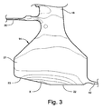
FIG. 3 is a partial vertical cross-sectional view of a HPT disk hub with indicated axial thermal gradients according to a HPT disk hub design; -
FIG. 4 is a partial vertical cross-sectional view of a HPT disk hub; -
FIG. 5 is a partial vertical cross-sectional view of a HPT disk hub; and -
FIG. 6 is a partial vertical cross-sectional view of a HPT disk hub in accordance with one aspect of the invention; - A typical prior art disk hub is shown in
Figure 1 atreference numeral 1, and includes ahub surface 2. Stress gradient lines 7-3 indicate progressively higher stresses towards thehub surface 2. - This occurs as the material at the
hub surface 2 increases in temperature and thermally expands. The interior material of thedisk hub 1 is cooler, as indicated by a relatively coolinterior area 8 of reduced stress that restrains the thermal expansion of the hotter material closer to thesurface 2 of thehub 1. The stress peaks in the center, as shown, and falls away at the opposing ends due to the axial free surfaces that permit the expansion. As described below, reducing the distance from the center of the hub to a free axial surface has been shown to reduce the magnitude of the central axial stress. -
Figure 2 illustrates a portion of aHPT section 10 of an aircraft high bypass ratio gas turbine engine. TheHPT section 10 includes first andsecond stage disks respective webs respective hubs stage disk hub 21 includes a hub surface and achamfer 23, as described in further detail below.Dovetail slots webs - The
first stage disk 14 includes aforward shaft 30 that is integral with theweb 18.Hub 21 of thefirst stage disk 14 includes a rearwardly-extendingaft shaft 42 that is press-fitted into engagement with abearing 44. Theshaft 42 includes a plurality ofopenings 46 that allow cooling air to enter theinterstage volume 48. Aninterstage seal 50 is positioned between thefirst stage disk 14 and thesecond stage disk 16, and includes anouter shell 52 and acentral disk 54 having ahub 56.Shell 52 is generally cylindrical with forward and aft-extendingcurved arms midportion 62 that supportsseal teeth 64 and attach to therespective disks - Referring now to
Figure 3 , thesurface 22 of thedisk hub 21 is provided with a radially-displacedchamfer 23 on the forward end of thehub surface 22. This places a free surface, i.e., a Acorner@, of thechamfer 23 immediately below the coolest portion of thehub 21, thereby forcing the axial stress to be the greatest at an off-center position, thereby decreasing its magnitude. This is shown inFigure 3 , where the area of greatest stress, indicated at X is shifted to a forwardly off-center position. - Optimum shape, angle, size and dimensions of the chamfer are determined empirically by implementing a design change and then reviewing the effect of the change through computer analysis to observe the resulting stresses, rather than by a purely analytical method. The design process is adapted to balance the decrease in axial stress with an accompanying increase in hoop stress caused by lowering the cross-sectional area of the
disk hub 21. - In a preferred version, the
chamfer 23 intersects the non-chamfered portion of thehub surface 22 at the same axial location as the center of maximum axial tensile stress. Thechamfer 23 is preferably planar, as shown, with radiused fore and aft transitions and may be between about 0 and 50 degrees. - Prior art disk hubs in a specific General Electric gas turbine engine were rated at 11,000 cold start cycles. Incorporation of the chamfer as shown and described above into a computer simulation resulted in an improvement to 15,300 cold start cycles, enabling the engine to meet program life requirements.
- Similar improvements may be obtained with a variety of techniques. As is shown in
Figure 4 , adisk 70 includes an integrally-formedweb 72 and adisk hub 74 with ahub surface 76. Thedisk 70 includes an integrally-formedforward shaft 78 and a rearwardly-extendingaft shaft 80. Thehub surface 76 is provided withradial grooves hub 74. Average hoop stress, burst margin and selected rim stress are other variables that must be taken into account. Thegrooves hub surface 76. Somewhat less material is removed from thehub 74 for a given amount of stress reduction in comparison with thechamfered hub surface 22 shown inFigure 3 , thereby minimizing the increase in disk hoop stress resulting from the reduction in disk cross-sectional area. - Another alternative is shown in
Figure 5 , where adisk 90 includes an integrally-formedweb 92 and adisk hub 94 with ahub surface 96. Thedisk 90 includes an integrally-formedforward shaft 98 and a rearwardly-extendingaft shaft 100. Thehub surface 96 is provided with a concave annular recess, the shape of which is defined by variable A, R1 and R2. Thermostructural DOE is used to determine the appropriate design space to achieve minimum stress in thehub 94. While the impact on the disk temperature may be moderate, this design may significantly reduce axial stress by decreasing the thermal gradient within thehub 94. - Referring now to
Figure 6 , a further modified design is illustrated. Adisk 110 includes an integrally-formedweb 112 and adisk hub 114 with ahub surface 116. Thedisk 110 includes an integrally-formedforward shaft 118 and a rearwardly-extendingaft shaft 120. The hub surface 166 is provided with a convex annular recess, the shape of which is defined by variables essentially as withFigure 5 . Thermostructural DOE is used to determine the appropriate design space to achieve minimum stress in thehub 114. While the impact on the disk temperature may be moderate, this design may significantly reduce axial stress by increasing the distance over which the thermal gradient is formed within thehub 114. This design illustrates the principle that any surface other than a planar axial cylindrical surface will achieve a reduction in peak axial stress. The objective is to reduce peak axial stress while minimizing compensating variations in other undesirable conditions. For example, cylindrical grooves in the hub surface would reduce peak axial stress, but would also introduce very high stress points at the sharp corners that would be highly detrimental to the operational life of the disk. As is evident from the foregoing, the radially-displaced portion of the disk hub surface may be planar, e.g.,Figures 2 and3 , or non-planar, e.g.,Figures 4-6 --the principal determining factor being the results achieved by DOE studies and the effect of the radially-displaced portion of the disk hub surface on axial stress, hoop stress, burst margin and rim stress. - A disk hub with reduced axial stress, and methods of reducing axial stress in a disk hub are disclosed above. Various details of the invention may be changed without departing from its scope. Furthermore, the foregoing description of the preferred aspect of the invention and the best mode for practicing the invention are provided for the purpose of illustration only and not for the purpose of limitation--the invention being defined by the claims.
Claims (4)
- A gas turbine engine disk, comprising:(a) a centrally disposed disk hub (21, 114) having an integrally-formed, radially outwardly extending web terminating at an outer end; and(b) the disk hub (21, 114) having a radially-displaced annular hub surface (23, 116) exposed to high pressure, high temperature discharge gases during engine operation, the radially-displaced annular hub surface acting as an axial free surface mitigating the formation of undesirable axial stress in the disk hub (21,114) CHARACTERIZED BY:(c) the radially-displaced annular hub surface (23, 116) includes at least one radially-extending annular convexly curved ring.
- A gas turbine engine disk according to claim 1, wherein the disk hub surface (23, 114) includes both a radially-displaced annular hub surface section and an annular cylindrical surface section parallel with the axis of rotation of the disk.
- A method of reducing axial stress in a disk hub (21, 74,94, 114) of a gas turbine disk, comprising the steps of:(a) determining the location of stress gradients in a gas turbine disk hub (21, 114);(b) forming a radially-displaced, axially-extending annular surface section in a disk hub surface of the disk hub (21, 114) that axially displaces the axial stress relative to with a geometrically-centered, lowest internal temperature portion of the disk hub (21, 114) for shifting maximum axial stress on the disk hub (21, 114) out of vertical alignment with a geometrically-centered portion of the disk hub (21, 114), thereby reducing the magnitude of the axial stress on the disk hub (21, 114) and, CHARACTERIZED BY(c) the radially-displaced, axially-extending annular surface in a disk hub including at least one radially extending annular convexly curved ring.
- A method according to claim 3, including forming the surface of the disk hub with both a radially-displaced annular hub surface section and an annular cylindrical surface section parallel with the axis of rotation of the disk.
Applications Claiming Priority (1)
| Application Number | Priority Date | Filing Date | Title |
|---|---|---|---|
| US11/306,224 US7578656B2 (en) | 2005-12-20 | 2005-12-20 | High pressure turbine disk hub with reduced axial stress and method |
Publications (2)
| Publication Number | Publication Date |
|---|---|
| EP1801349A1 EP1801349A1 (en) | 2007-06-27 |
| EP1801349B1 true EP1801349B1 (en) | 2014-02-26 |
Family
ID=37944547
Family Applications (1)
| Application Number | Title | Priority Date | Filing Date |
|---|---|---|---|
| EP06126554.2A Not-in-force EP1801349B1 (en) | 2005-12-20 | 2006-12-19 | High pressure turbine disk hub with reduced axial stress and method |
Country Status (3)
| Country | Link |
|---|---|
| US (1) | US7578656B2 (en) |
| EP (1) | EP1801349B1 (en) |
| JP (1) | JP5270831B2 (en) |
Families Citing this family (15)
| Publication number | Priority date | Publication date | Assignee | Title |
|---|---|---|---|---|
| GB0614972D0 (en) * | 2006-07-28 | 2006-09-06 | Rolls Royce Plc | A mounting disc |
| US8172506B2 (en) * | 2008-11-26 | 2012-05-08 | General Electric Company | Method and system for cooling engine components |
| US8662845B2 (en) | 2011-01-11 | 2014-03-04 | United Technologies Corporation | Multi-function heat shield for a gas turbine engine |
| US8840375B2 (en) | 2011-03-21 | 2014-09-23 | United Technologies Corporation | Component lock for a gas turbine engine |
| FR2974863B1 (en) * | 2011-05-06 | 2015-10-23 | Snecma | TURBOMACHINE BLOWER DISK |
| US8936439B2 (en) * | 2011-07-11 | 2015-01-20 | Hamilton Sundstrand Corporation | Radial turbine backface curvature stress reduction |
| EP2639407A1 (en) | 2012-03-13 | 2013-09-18 | Siemens Aktiengesellschaft | Gas turbine arrangement alleviating stresses at turbine discs and corresponding gas turbine |
| US10119400B2 (en) | 2012-09-28 | 2018-11-06 | United Technologies Corporation | High pressure rotor disk |
| KR101828474B1 (en) * | 2015-06-16 | 2018-02-12 | 두산중공업 주식회사 | Turbine disk including bore groove |
| US10024170B1 (en) * | 2016-06-23 | 2018-07-17 | Florida Turbine Technologies, Inc. | Integrally bladed rotor with bore entry cooling holes |
| US10443387B2 (en) * | 2017-05-24 | 2019-10-15 | Honeywell International Inc. | Turbine wheel with reduced inertia |
| EP3406847A1 (en) | 2017-05-26 | 2018-11-28 | Siemens Aktiengesellschaft | Gas turbine engine rotor disc, corresponding gas turbine rotor disc assembly and gas turbine engine |
| US10794190B1 (en) * | 2018-07-30 | 2020-10-06 | Florida Turbine Technologies, Inc. | Cast integrally bladed rotor with bore entry cooling |
| EP3633145A1 (en) * | 2018-10-04 | 2020-04-08 | Rolls-Royce plc | Reduced stress in compressor disc |
| US10876429B2 (en) | 2019-03-21 | 2020-12-29 | Pratt & Whitney Canada Corp. | Shroud segment assembly intersegment end gaps control |
Family Cites Families (12)
| Publication number | Priority date | Publication date | Assignee | Title |
|---|---|---|---|---|
| US2951340A (en) * | 1956-01-03 | 1960-09-06 | Curtiss Wright Corp | Gas turbine with control mechanism for turbine cooling air |
| GB2112461A (en) * | 1981-12-22 | 1983-07-20 | Rolls Royce | Turbine disc hub cooling means of a gas turbine engine |
| DE3400835A1 (en) * | 1984-01-12 | 1985-07-18 | Klöckner-Humboldt-Deutz AG, 5000 Köln | Rotor wheel for turbo-engines |
| DE3708507A1 (en) * | 1987-03-16 | 1988-09-29 | Siemens Ag | METHOD FOR PRODUCING TURBINE WHEEL DISCS WITH LOCAL HIGH PRESSURE TENSIONS IN THE HUB HOLE |
| US5275534A (en) * | 1991-10-30 | 1994-01-04 | General Electric Company | Turbine disk forward seal assembly |
| FR2712029B1 (en) * | 1993-11-03 | 1995-12-08 | Snecma | Turbomachine provided with a means for reheating the turbine disks when running at high speed. |
| US5630703A (en) * | 1995-12-15 | 1997-05-20 | General Electric Company | Rotor disk post cooling system |
| JP3149774B2 (en) * | 1996-03-19 | 2001-03-26 | 株式会社日立製作所 | Gas turbine rotor |
| US6457942B1 (en) * | 2000-11-27 | 2002-10-01 | General Electric Company | Fan blade retainer |
| US7241111B2 (en) * | 2003-07-28 | 2007-07-10 | United Technologies Corporation | Contoured disk bore |
| US7464577B2 (en) * | 2004-07-01 | 2008-12-16 | General Electric Company | Method for fabricating rotary machines |
| EP1614857A1 (en) * | 2004-07-05 | 2006-01-11 | Siemens Aktiengesellschaft | Turbomachine with a rotor comprising at least one drilled disc |
-
2005
- 2005-12-20 US US11/306,224 patent/US7578656B2/en active Active
-
2006
- 2006-12-19 EP EP06126554.2A patent/EP1801349B1/en not_active Not-in-force
- 2006-12-20 JP JP2006342780A patent/JP5270831B2/en not_active Expired - Fee Related
Also Published As
| Publication number | Publication date |
|---|---|
| JP2007170390A (en) | 2007-07-05 |
| US20070140864A1 (en) | 2007-06-21 |
| US7578656B2 (en) | 2009-08-25 |
| JP5270831B2 (en) | 2013-08-21 |
| EP1801349A1 (en) | 2007-06-27 |
Similar Documents
| Publication | Publication Date | Title |
|---|---|---|
| EP1801349B1 (en) | High pressure turbine disk hub with reduced axial stress and method | |
| EP1801347B1 (en) | High pressure turbine disk hub with curved hub surface and method | |
| US8100653B2 (en) | Gas-turbine blade featuring a modular design | |
| US5688108A (en) | High temperature rotor blade attachment | |
| EP2372088B1 (en) | Turbofan flow path trenches | |
| US4682935A (en) | Bowed turbine blade | |
| JP4802192B2 (en) | Turbine case reinforcement in gas turbine jet engines. | |
| EP1138431B2 (en) | Method of repairing an airfoil | |
| EP1681473B1 (en) | Compressor wheel | |
| EP1361340B1 (en) | Turbine blade with a root notch | |
| EP2484867B1 (en) | Rotating component of a turbine engine | |
| EP2412926B1 (en) | Hollow blade for a gas turbine | |
| US7513747B2 (en) | Rotor for a compressor | |
| EP2567070B1 (en) | Light weight shroud fin for a rotor blade | |
| US7331763B2 (en) | Turbine disk | |
| US6991433B2 (en) | Drum, in particular a drum forming a turbomachine rotor, a compressor, and a turboshaft engine including such a drum | |
| US5593282A (en) | Turbomachine rotor construction including a serrated root section and a rounded terminal portion on a blade root, especially for an axial-flow turbine of a gas turbine engine | |
| US20150098802A1 (en) | Shrouded turbine blisk and method of manufacturing same | |
| US20090263251A1 (en) | Reduced weight blade for a gas turbine engine | |
| US6957948B2 (en) | Turbine blade attachment lightening holes | |
| US9033669B2 (en) | Rotating airfoil component with platform having a recessed surface region therein |
Legal Events
| Date | Code | Title | Description |
|---|---|---|---|
| PUAI | Public reference made under article 153(3) epc to a published international application that has entered the european phase |
Free format text: ORIGINAL CODE: 0009012 |
|
| AK | Designated contracting states |
Kind code of ref document: A1 Designated state(s): AT BE BG CH CY CZ DE DK EE ES FI FR GB GR HU IE IS IT LI LT LU LV MC NL PL PT RO SE SI SK TR |
|
| AX | Request for extension of the european patent |
Extension state: AL BA HR MK YU |
|
| 17P | Request for examination filed |
Effective date: 20071227 |
|
| AKX | Designation fees paid |
Designated state(s): DE FR GB |
|
| 17Q | First examination report despatched |
Effective date: 20080211 |
|
| GRAP | Despatch of communication of intention to grant a patent |
Free format text: ORIGINAL CODE: EPIDOSNIGR1 |
|
| INTG | Intention to grant announced |
Effective date: 20130822 |
|
| GRAS | Grant fee paid |
Free format text: ORIGINAL CODE: EPIDOSNIGR3 |
|
| GRAA | (expected) grant |
Free format text: ORIGINAL CODE: 0009210 |
|
| AK | Designated contracting states |
Kind code of ref document: B1 Designated state(s): DE FR GB |
|
| REG | Reference to a national code |
Ref country code: GB Ref legal event code: FG4D |
|
| REG | Reference to a national code |
Ref country code: DE Ref legal event code: R096 Ref document number: 602006040370 Country of ref document: DE Effective date: 20140410 |
|
| REG | Reference to a national code |
Ref country code: DE Ref legal event code: R097 Ref document number: 602006040370 Country of ref document: DE |
|
| PLBE | No opposition filed within time limit |
Free format text: ORIGINAL CODE: 0009261 |
|
| STAA | Information on the status of an ep patent application or granted ep patent |
Free format text: STATUS: NO OPPOSITION FILED WITHIN TIME LIMIT |
|
| 26N | No opposition filed |
Effective date: 20141127 |
|
| REG | Reference to a national code |
Ref country code: DE Ref legal event code: R097 Ref document number: 602006040370 Country of ref document: DE Effective date: 20141127 |
|
| REG | Reference to a national code |
Ref country code: FR Ref legal event code: PLFP Year of fee payment: 10 |
|
| REG | Reference to a national code |
Ref country code: FR Ref legal event code: PLFP Year of fee payment: 11 |
|
| PGFP | Annual fee paid to national office [announced via postgrant information from national office to epo] |
Ref country code: GB Payment date: 20161228 Year of fee payment: 11 |
|
| PGFP | Annual fee paid to national office [announced via postgrant information from national office to epo] |
Ref country code: FR Payment date: 20161227 Year of fee payment: 11 |
|
| PGFP | Annual fee paid to national office [announced via postgrant information from national office to epo] |
Ref country code: DE Payment date: 20161229 Year of fee payment: 11 |
|
| REG | Reference to a national code |
Ref country code: DE Ref legal event code: R119 Ref document number: 602006040370 Country of ref document: DE |
|
| GBPC | Gb: european patent ceased through non-payment of renewal fee |
Effective date: 20171219 |
|
| REG | Reference to a national code |
Ref country code: FR Ref legal event code: ST Effective date: 20180831 |
|
| PG25 | Lapsed in a contracting state [announced via postgrant information from national office to epo] |
Ref country code: FR Free format text: LAPSE BECAUSE OF NON-PAYMENT OF DUE FEES Effective date: 20180102 Ref country code: DE Free format text: LAPSE BECAUSE OF NON-PAYMENT OF DUE FEES Effective date: 20180703 |
|
| PG25 | Lapsed in a contracting state [announced via postgrant information from national office to epo] |
Ref country code: GB Free format text: LAPSE BECAUSE OF NON-PAYMENT OF DUE FEES Effective date: 20171219 |