-
The present invention relates to the field of vehicles for transporting materials, in particular building materials. Many vehicle solutions are already currently in use and well known for transporting building materials. Such vehicles usually comprise a chassis, displacement means adapted to displacement of the vehicle, such as wheels, rollers, chains, tracks, or the like, affixed or connected to the chassis, and material retaining means adapted to hold the materials in place during transport. Typical examples of such vehicles are forklift trucks, palette trolleys, automobile transport rams and the like.
-
The building industry has many requirements for transportation of materials, one of these being safety, in particular when working with heavy, bulky or oversized building elements. These safety requirements are even more drastic when working at height, such as, say, when working on roofing, since coupled with the danger of the building elements falling to the ground and damaging other material or persons, other risks are omnipresent:
- those manipulating the heavy, bulky or oversized building elements above the ground are at risk from losing their balance, or being knocked over by said elements, leading to potentially catastrophic consequences for this group of workers ;
- the oversized or bulky building elements risk being caught in the wind and overturning ;
- limbs or articulations of the workforce are at risk from cuts or severage by falling or slipping building elements.
-
When covering or roofing a building structure with covering elements, for example, such as panels made from galvanized steel, or aluminium, special precautions have to be taken to protect the workforce from the potentially catastrophic consequences mentioned above, especially in view of the extremely bulky and unwieldy nature of the covering elements, which generally tend to be more than several metres in length and width. At present, these elements can only be transported and handled manually, which involves an increased workforce, increased risk, and naturally increased costs.
-
It has therefore been a long felt need to find a solution to the problems mentioned above, by reducing risk to the workforce, workforce numbers and consequently reducing cost of manipulating and transporting heavy, bulky or oversized building elements.
-
The present invention thus proposes a materials transport vehicle, comprising a chassis, and a displacement means adapted to displacement of the vehicle, the chassis comprising a frame and a materials retaining means adapted to retain materials to be transported on the vehicle, wherein the displacement means is adapted in height and dimension to enable displacement of the vehicle, and any materials loaded thereon, on and across a grid of parallel interconnected load-bearing construction elements.
-
In one preferred embodiment according to the invention, the displacement means are affixed to said frame either permanently or removably, and preferably removably.
-
In accordance with the present invention, the grid of parallel interconnected load-bearing construction elements is preferably made from a building material selected from the group consisting of wood, metal, concrete, and combinations thereof. Even more preferably, the grid of parallel interconnected load-bearing construction elements is made of metal girders, beams, or rails. Preferably, the grid of parallel interconnected load-bearing construction elements forms a roof framework, but alternatively, or combined with the roof framework, the grid of parallel interconnected load-bearing construction elements can form a wall framework. This framework thus corresponds to may modern building structures and practises at present, whereby a load bearing skeleton, or backbone, roof and wall structure is created from the construction elements listed above. These load bearing construction elements, for example, metal girders, are generally arranged in parallel, both vertically, thereby forming the wall framework, or slopingly or horizontally, thereby forming the roofing framework. Manipulating cumbersome, bulky or awkward materials on such structures, such as for example, roofing elements, is extremely time consuming and potentially dangerous for the workforce, even with the presence of nets, walkboards and other protective measures. The vehicle of the present invention uses these structures to both charge, discharge, and displace materials across the interconnected grid, which in essence serves as a support surface for the displacement means.
-
The displacement means preferably comprises a plurality of wheels or rollers, but in an alternative embodiment, comprises a plurality of sliding feet. The displacement means are located on the chassis of the vehicle in a spatial orientation corresponding to the spacing of the parallel interconnected load-bearing construction elements, and in particular and most preferably, the displacement means are located on the chassis at a distance equal to the distance separating centre points of the longitudinal axes of two directly adjacent parallel interconnected load-bearing construction elements. In this way, two adjacent parallel load bearing construction elements provide the surface on which the displacement means can operate, and enable displacement of the vehicle. In particularly preferred embodiments, first displacement means are located at a location on the chassis at a distance of between about 1300 mm to about 3000 mm from second displacement means located at another location on the chassis. These distances correspond in general to the range of distances used in the building industry between two adjacent and parallel load-bearing construction elements such as metallic girders.
-
In yet another preferred embodiment of the vehicle of the invention, the vehicle further comprises automatically activated anti-tip braking means, preventing the vehicle from moving outside of the grid of parallel interconnected load-bearing construction elements and tipping over. The automatically activated anti-tip braking means more preferably comprise a counter-weight brake. The counter-weight brake comprises a metallic generally U- or V-shaped clip about a retaining pin located at a fulcrum point which is mounted on the chassis or an axis of the vehicle. Each branch of the U- or V-shaped clip has a different conformation according to its assigned function. A first branch of the clip is conformed at its outermost extremity into a substantially circular shape. The substantially circular shaped extremity presses onto the load-bearing construction element under its own weight, for example, a girder, and is displaced along with the vehicle as the vehicle is displaced. It also projects out in front of, or behind, the vehicle, along the axis of displacement. When the end of the girder is reached, the weight of the substantially circular branch caused the clip to rotate about the fulcrum, thereby constraining the second branch into a constrained position or braking position as will be described hereafter. The second branch is conformed as a substantially straight branch with an upward arc at its extremity. The upward arc preferably has a curvature that is slightly greater than the curvature of the displacement means, which, in the case of wheels or rollers, is the curavture formed by part of the circumference of these wheels or rollers. As mentioned, when the first branch is displaced over the end of a girder, the rotation about the fulcrum causes the second branch to move upward, thereby bringing the extremity of the second branch into contact with the wheel circumference, at a point where friction will be greatest between the upwardly moving second branch and the wheel. Since the wheel bears down on the upwardly moving branch extremity, a wedge effect causes the wheel to stop moving, thereby preventing the vehicle from falling off the edge of the grid of parallel interconnected load-bearing construction elements.
-
In still yet another preferred embodiment, the vehicle further comprises self-hoisting and lowering means adapted to hoist and lower the vehicle onto, and off, a roof. The advantage of having such means is that it becomes possible to use just the vehicle on its own to bring itself up the wall and onto the roof, thereby avoiding the use of a crane or other hoisting means, again saving time, money and labour. The self-hoisting and lowering means preferably comprise a winch, more preferably an electric winch, a winch cable, and a hook connected to the winch cable. Although the hook can be shaped like any other traditional hook associated with hoisting machines, in the present invention, it is preferred for the hook to be dimensioned such as to be able to load materials onto the vehicle. Since one of the ideas behind the invention is the ability to displace bulky and cumbersome materials along a roof or wall framework, the hook has been adapted. The hook that is preferably used in the invention therefore has a cable attachment ring, for attaching a hoisting cable, from which project two arms in substantially V-shaped fashion. The extremities of the V are respectively connected to each other by a connector element. The connector element projects substantially perpendicularly to the plane of the V, such that it becomes possible to load, and retain during loading, any materials loaded onto the V or loaded partially onto the vehicle and the V. Further explanation will be given in the detailed description of the figures.
-
In addition to all of the above, the vehicle according to the present invention further comprises a materials bearing frame mounted on the chassis which is movable in a direction orthogonal to a longitudinal axis of the parallel interconnected construction elements. Such a frame is generally made of metal, or optionally from a composite material, such as a plastic or a high impact plastic, and preferably of aluminium, more preferably of tubular aluminium. The frame is movable orthogonally to the longitudinal axis of displacement in order to provide for greater amplitude of handling of the materials that are loaded onto the vehicle, and with which it becomes possible to displace materials along the interconnected grid, both in the direction of displacement, but also either side of said direction.
-
An even more preferred embodiment of the vehicle of the present invention is obtained by providing at least one load-bearing extension arm. The at least one load-bearing extension arm is preferably made of the same material as the materials bearing frame, and can be mounted articulated at a corner of said frame, thereby enabling the vehicle to displace materials having a span that exceeds the support area provided by the frame alone. Optionally, but preferably, the materials bearing frame further comprises at least one materials retaining abutment. The at least one materials retaining abutment preferably comprises a tubular aluminium body, inside of which is mounted a threaded shaft. The abutment is provided with, at one extremity of the aluminium body, an shock absorbing sleeve that surrounds the aluminium tube. The sleeve can be made of any suitable shock resistant material, for example, ABS plastic, polyurethane foam, wood, and the like. The threaded shaft extends out of the other extremity of the tube and cooperates with a nut or locking mechanism that can be threaded onto the shaft, thereby allowing for the abutment to be attached to the tubing of the extension arm or frame.
-
In addition to the abutments on the frame and extension arm, the vehicle also preferably comprises retaining plates as the materials retaining means of the chassis. These plates comprise projecting flanges that slidingly mate with an exterior surface of the parallel interconnected load-bearing construction elements, when they are lowered, and help to stabilize the vehicle against destabilising forces exerted on the vehicle when it is being loaded. When these plates are raised, they serve to retain the loaded materials from slipping off the vehicle. These plates are coated with an anti-friction coating, such as PTFE, or polyethylene, in order to reduce friction wear on the plates and a build-up of heat when the plates move along the interconnected elements. The plates can be locked into place in either a vertical or horizontal position via appropriate locking means.
-
In still yet another preferred embodiment, the vehicle further comprises an electrical supply means. In such a case, the electrical supply means preferably comprises a supply cable, a transformer or a distributor, and one or more electrical sockets connected to the transformer or distributor. The advantages to this is that the electrical supply means can also supply electricity to the winch, and the supply cable can be provided, for example, as an automated reel system, that lets out or pulls in the cable as required, depending on the location of the vehicle on the roof or the wall of the building, and can be connected to another electrical power supply on the ground. The location of electrical sockets on the vehicle also means that it is possible to use electrical tools in the vicinity of the vehicle, and thereby obviate the need to have a potentially dangerous entanglement of multiple power supplies coming up from the ground.
-
In addition to the above preferred embodiments, the vehicle can also preferably be provided with one or more footplates mounted on the chassis, a tool holder, security harness attachment rings.
-
The vehicle according to the present invention can thus be used for transporting bulky, or cumbersome materials, along or across a roof framework or even along a wall framework. Although the materials that the vehicle can transport are varied, it is particularly adapted to materials such as plates, boards, planks, girders, beams, roofing tiles, roofing sheets, and corrugated sheets, wall or roof covering elements, and most preferably corrugated covering sheets.
-
Although the vehicle can be used pre-assembled, it is particularly preferred that it be provided as a kit of parts, which can be assembled on site.
-
The vehicle according to the present invention will now be described furhter in reference to the figures, and detailed description of a preferred embodiment. It is to be understood that the figures and the corresponding description are given merely as an example of the possibilities of the present invention.
Brief Description of the Figures
-
- Figure 1 is a schematic perspective representation of a preferred vehicle according to the present invention.
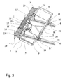
- Figure 2 is also a schematic perspective representation of the preferred vehicle of Figure 1, viewed from another angle.
- Figure 3a is a schematic top plan representation a preferred variant of the vehicle of Figure 1.
- Figure 3b is a schematic top plan representation of the vehicle of Figure 1.
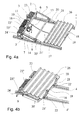
- Figure 4a is a schematic side perspective representation of the vehicle of Figure 3a upon commencement of loading building materials onto the vehicle.
- Figure 4b is another schematic perspective representation of the vehicle of Figure 1, after the building materials have been loaded onto the vehicle.
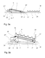
- Figure 5a is a schematic side representation of the vehicle of Figure 4a.
- Figure 5b is a schematic side representation of the vehicle of Figure 4a after loading of building materials onto the vehicle.
- Figure 6a is a schematic perspective representation of the vehicle in Figure 3a, showing a deployed extension arm.
- Figure 6b a schematic close up perspective representation of the vehicle in Figure 6a, showing the extension arm folded back to the frame.
- Figure 6c is a schematic close-up representation of a retaining abutment.
- Figure 7 is a schematic side view of a close-up of the displacement means of the vehicle of Figure 1.
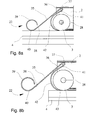
- Figure 8a is a schematic side view of the anti-tipping brake of the vehicle of Figure 1 whilst the vehicle is in motion on the grid of parallel interconnected load-bearing construction elements.
- Figure 8b is a schematic side view of the anti-tipping brake in Figure 8a, shown in
- Figure 9 is a schematic perspective representation of two vehicles according to Figure 1 positioned in parallel on adjacent pairs of load bearing construction elements, and carrying large span materials spread over the combined span of both vehicles.
Examples.
-
An example of a vehicle according to the present invention is depicted in Figure 1, and identified by the general reference number 1. The vehicle comprises a chassis 2 and displacement means 3 adapted to displacement of the vehicle and attached to the chassis 2. In the present example, the displacement means 3 are four wheels, only one of which is visible in the Figure. The wheels of the vehicle sit on a pair of load bearing girders or rails 4, 4' typically found in modern buildings as the skeleton for the walls and the roof. Pairs of wheels 3 mounted on the chassis are connected together and aligned along the girders 4,4' via panels 5,5'. A load bearing frame 6 is mounted on the chassis 2 and can slide perpendicularly to the axis of movement of the vehicle, enabling loads to be moved more conveniently into position. The load bearing frame 6 also has a load bearing extension arm 7, attached via a rotating articulation 8 for transporting very large span materials. Both the frame and the arm can have retaining abutments 9, that can slide into the tubular aluminium frame 6, and be fastened for example with a screw thread shaft and corresponding nut or similar mechanism. The frame is slightly inclined to facilitate loading and unloading of material, with the higher end of the frame being mounted on the chassis near to an electric winch 10. The electric winch 10 has a motor 11 and a control circuit 12, for winding or unwinding the winch 10. The motor 11 and control circuit 12 receive electricity from an electrical supply 13, which is in turn connected to a self-reeling cable 14 that is plugged into an electrical supply on the ground. The electrical supply 13 also provides electrical power to several electric sockets 15, enabling power tools to be plugged in and used in the vicinity without having to trail a multitude of cables to the ground. As can be seen from the figure, the sockets, winch, motor, and control circuit are all mounted on a tool holder 16, on which the workforce can lay their tools. The winch 10 is connected via a winch cable 17 to a substantially V-shaped hook 18, having a connector plate 19 linking the two extremities of each arm of the V. The connector plate 19 rises up substantially perpendicularly to the plane of the arms of the V, thereby providing a means to retain and engage with materials to be loaded onto the frame 6, as will be explained in relation to a further figure. Adjacent the panels 5 are material retaining means 20,20' in the shape of plates that can be set in two different positions. In a first horizontal position, the retaining plates 20,20' are substantially in alignment with the slope of the frame 6, and mate slidingly with the girders 4,4'. In addition, the plates comprises flanges 21,21' that project either side of the girder and stabilize the vehicle when it is stationary and being loaded or unloaded with material. The vehicle further includes an anti-tipping brake 22,22',22", the details and functioning of which are more apparent in Figure 8, and will be described further in the specification. Additional features that are present in the vehicle illustrated in Figure 1 include footplates 23,23',23", that enable workers to stand or kneel while using the vehicle and thereby facilitate manipulation of the materials to be loaded, unloaded and displaced. As an additional safety measure, the footplates also comprise tip stop bars 24, which in the event that a heavy load should be moved onto the footplates and thereby destabilise the vehicle, will come to rest against the girders 4,4' and prevent the vehicle from further imbalance. Other security features include harness attachment rings 25, that enable workers to clip in their safety harnesses to the vehicle to prevent them from falling away from the vehicle when working on, or around it.
-
Figure 2 is simply an alternative view of Figure 1, shown at a different angle so that the winch 10, winch cable 17, hook 18, electrical supply 13, and retaining plates 20,20' are more clearly visible.
-
Figures 3a and 3b are top plan representations of vehicles according to the present invention. Figure 3b is simply another representation of the vehicle in Figures 1 and 2, but in Figure 3a, one can see that the chassis 2 is substantially the same width as the frame 6, which corresponds to a greater distance between girders. Figure 3 is given as a direct comparison of the relationship between the various components at different inter-girder distances. The remainder of the vehicle of Figure 3a is equipped in exactly the same way as the vehicle of Figure 1.
-
Figures 4a and 4b show the alternative vehicles represented above in different stages of loading of a building material onto the vehicle. In Figure 4a, the winch cable 17 is unwound, and the hook 18 extends beyond the vehicle. One or more building elements, such as a corrugated steel roofing plate 26, is or are placed onto the V-shaped arms of the hook 18, and the connector plate 19 prevents the corrugated roofing plate 26 from moving away from the vehicle. At this point in time, the corrugated roofing plate 26 is substantially resting on a pair of parallel girders 4,4'. The winch is then activated to wind the roofing plate or plates and bring them up onto the frame 6. It is noted that during the loading operation, the retaining plates 20,20' are positioned substantially in alignment with the slope of the frame 6 and thereby do not hinder the translational movement of the roofing plates 26 onto said frame. The connector plate 19 also applies a passive push force to the roofing plates 26 in the direction of the frame 6.
-
In Figure 4b, the loading operation has terminated, and the winch 10 has been wound in. At this point, one can see that the roofing plates 26 are now laying in position on the frame 6, and that they are held in position by the retaining plates 20,20', which have been moved and locked into a substantially upright position.
-
Figures 5a and 5b show the same operation from a side view of the vehicle.
-
Figures 6a, 6b and 6c show additional details that are preferred embodiments of the present invention. For example, Figure 6a shows the vehicle with a deployed extension arm 7, and the articulation 8 by which the arm is connected to the frame 6. Figure 6b shows a view of vehicle of the present invention limited to the part representing the arm 7 folded back against the frame, that is, in its undeployed state. Figure 6c shows a close-up view of a retainer abutment, such as are present on the frame 6 and the arm 7 of Figure 6b. These abutment retainers 9 can also be made of the same material as the frame 6 and arm 7, for example in tubular aluminium. As shown in Figure 6c, the abutment retainer 9 can be lodged in a groove provided in the tubular aluminium frame 6 or arm 7. The retainer 9, which comprises a protective sleeve 45 made of wear and shock resistant material, can be attached for example, by means of a threaded shaft 44 running through the retainer, against which is screwed a nut 46 or other corresponding closure mechanism. Similar equivalent attachment mechanisms, known to the skilled person, such as latches, twist-locks and the like, may be used instead. In this way, the abutment retainers can easily be withdrawn or placed according to requirements. The abutment retainers serve to further hold the materials in place once loaded onto the frame, their use being advantageous, but optional.
-
Figure 7 shows a side view representation of the displacement means of the present invention. A wheel 3 is mounted via an axle 28 onto the chassis 2. The wheel 3 sits on the girder 4. An annular flange 29, attached to the wheel 3 or forming an integral part thereof, and in line with the axle 28, overlaps with a face of the girder adjacent and perpendicular to the face on which the wheel 3 rests. The annular flange 29 serves to guide the wheel 3 along the girder 4, whereby an inner surface 30 of the flange 29 bears down on the face 31 of the girder perpendicular to the face on which the wheel 3 moves. On the side opposite the annular flange 29, a supporting arm 32 projects downwards from the chassis 2 and houses a roller or smaller wheel 33. This roller 33 is mounted in the support arm 32 such that its rolling contact surface is perpendicular to that of the wheel 3, and such that the roller will only come into contact with the adjacent face 34 of the girder 4 if the vehicle should move sideways off its intended trajectory. In other words, the roller 33 serves as a stabiliser for the vehicle in the event that it should, for whatever reason, start to lose its initial longitudinal trajectory and start to fall off the girder 4. The difference with the annular flange 29 is that the flange creates a resistive force, due to friction, and will slow the vehicle, whereas the roller 33 will continue to allow movement of the vehicle in the intended direction. The distance between the inner surface 30 of the flange 29, i.e. the surface that bears down on the girder face 31, and the stabiliser roller 33 can be pre-set in advance as a function of the width of the girder or beam on which the vehicle is to be displaced, or adapted accordingly with simple tools on the interconnected grid of construction elements.
-
Figures 8a and 8b show in greater detail, the arrangement of the anti-tip brake 22. The automatically activated anti-tip braking means 22 comprise a counter-weight brake. The counter-weight brake 22 comprises a metallic and generally U- or V-shaped clip 36 about a retaining pin 37 located at a fulcrum point which is mounted on the chassis 2 or an axis of the vehicle. Each branch of the U- or V-shaped clip 36 has a different conformation according to its assigned function. A first branch 38 of the clip is conformed at its outermost extremity 39 into a substantially circular shape. The substantially circular shaped extremity 39 is presses onto the load-bearing construction element under its own weight, for example, a girder, and the clip, at a point of contact 40, is displaced along with the vehicle as the vehicle is displaced. It also projects out in front of, or behind, the vehicle, along the axis of displacement. When the end of the girder 4 is reached, the weight of the substantially circular shaped extremity 39 of the first branch 38 no longer bears down against the girder 4, and thus falls and causes the clip to rotate anti-clockwise or clockwise depending on the location of braking means, about the fulcrum at the retaining pin 37, thereby constraining the second branch 41 into a constrained position or braking position as will be described hereafter. The second branch 41 is conformed as a substantially straight branch with an upward arc 42 at its extremity. The upward arc 42 preferably has a curvature slightly greater than the curvature of the wheel, that is, the curvature formed by part of the circumference of the wheel or roller. As mentioned, when the first branch 38 is displaced over the end of a girder 4, the branch falls under its own weight and a rotation of the clip is effected about the fulcrum 37, which causes the second branch 41 to move upward, thereby bringing the extremity of the second branch into frictional wedging contact with the wheel circumference 43.,This frictional contact , causes the wheel to stop moving, thereby preventing the vehicle from falling off the edge of the grid of parallel interconnected load-bearing construction elements.
-
Figure 9 shows a representation of the use of two vehicles to share and spread the load and displace a very large span material, in this corrugated roofing plates 26. Each vehicle travels along a pair of girders, and the roofing plates are loaded and unloaded onto both vehicles simultaneously, using the winches and hooks described above. In this way, it is possible with the vehicle of the present invention to manipulate, load, unload and displace even very broad materials.