EP1801022A1 - Package adapted to receive an opening device - Google Patents
Package adapted to receive an opening device Download PDFInfo
- Publication number
- EP1801022A1 EP1801022A1 EP05445096A EP05445096A EP1801022A1 EP 1801022 A1 EP1801022 A1 EP 1801022A1 EP 05445096 A EP05445096 A EP 05445096A EP 05445096 A EP05445096 A EP 05445096A EP 1801022 A1 EP1801022 A1 EP 1801022A1
- Authority
- EP
- European Patent Office
- Prior art keywords
- panel
- top panel
- flaps
- longitudinal direction
- package
- Prior art date
- Legal status (The legal status is an assumption and is not a legal conclusion. Google has not performed a legal analysis and makes no representation as to the accuracy of the status listed.)
- Granted
Links
- 238000007789 sealing Methods 0.000 claims description 64
- 230000000295 complement effect Effects 0.000 claims description 5
- 230000001419 dependent effect Effects 0.000 description 6
- 238000000034 method Methods 0.000 description 5
- 235000013305 food Nutrition 0.000 description 4
- 241000227653 Lycopersicon Species 0.000 description 3
- 235000007688 Lycopersicon esculentum Nutrition 0.000 description 3
- 235000011389 fruit/vegetable juice Nutrition 0.000 description 3
- 235000013336 milk Nutrition 0.000 description 3
- 239000008267 milk Substances 0.000 description 3
- 210000004080 milk Anatomy 0.000 description 3
- 235000015067 sauces Nutrition 0.000 description 3
- 235000014101 wine Nutrition 0.000 description 3
- 239000000109 continuous material Substances 0.000 description 2
- 230000002452 interceptive effect Effects 0.000 description 2
- 239000005022 packaging material Substances 0.000 description 2
- 230000009286 beneficial effect Effects 0.000 description 1
- 239000013067 intermediate product Substances 0.000 description 1
- 239000007788 liquid Substances 0.000 description 1
- 239000000463 material Substances 0.000 description 1
- 238000012986 modification Methods 0.000 description 1
- 230000004048 modification Effects 0.000 description 1
- 229920000642 polymer Polymers 0.000 description 1
- 239000002699 waste material Substances 0.000 description 1
Images



Classifications
-
- B—PERFORMING OPERATIONS; TRANSPORTING
- B65—CONVEYING; PACKING; STORING; HANDLING THIN OR FILAMENTARY MATERIAL
- B65D—CONTAINERS FOR STORAGE OR TRANSPORT OF ARTICLES OR MATERIALS, e.g. BAGS, BARRELS, BOTTLES, BOXES, CANS, CARTONS, CRATES, DRUMS, JARS, TANKS, HOPPERS, FORWARDING CONTAINERS; ACCESSORIES, CLOSURES, OR FITTINGS THEREFOR; PACKAGING ELEMENTS; PACKAGES
- B65D5/00—Rigid or semi-rigid containers of polygonal cross-section, e.g. boxes, cartons or trays, formed by folding or erecting one or more blanks made of paper
- B65D5/42—Details of containers or of foldable or erectable container blanks
- B65D5/72—Contents-dispensing means
- B65D5/74—Spouts
- B65D5/746—Spouts formed separately from the container
-
- B—PERFORMING OPERATIONS; TRANSPORTING
- B65—CONVEYING; PACKING; STORING; HANDLING THIN OR FILAMENTARY MATERIAL
- B65D—CONTAINERS FOR STORAGE OR TRANSPORT OF ARTICLES OR MATERIALS, e.g. BAGS, BARRELS, BOTTLES, BOXES, CANS, CARTONS, CRATES, DRUMS, JARS, TANKS, HOPPERS, FORWARDING CONTAINERS; ACCESSORIES, CLOSURES, OR FITTINGS THEREFOR; PACKAGING ELEMENTS; PACKAGES
- B65D5/00—Rigid or semi-rigid containers of polygonal cross-section, e.g. boxes, cartons or trays, formed by folding or erecting one or more blanks made of paper
- B65D5/02—Rigid or semi-rigid containers of polygonal cross-section, e.g. boxes, cartons or trays, formed by folding or erecting one or more blanks made of paper by folding or erecting a single blank to form a tubular body with or without subsequent folding operations, or the addition of separate elements, to close the ends of the body
- B65D5/06—Rigid or semi-rigid containers of polygonal cross-section, e.g. boxes, cartons or trays, formed by folding or erecting one or more blanks made of paper by folding or erecting a single blank to form a tubular body with or without subsequent folding operations, or the addition of separate elements, to close the ends of the body with end-closing or contents-supporting elements formed by folding inwardly a wall extending from, and continuously around, an end of the tubular body
- B65D5/064—Rectangular containers having a body with gusset-flaps folded outwardly or adhered to the side or the top of the container
Definitions
- the invention relates to a package having an extended top panel. It is contemplated to use the package for wet or dry pourable food products, such as juice, milk, wine, tomato sauce, cornflakes or the like, and the basic design concept of the package is therefore adapted to make this contemplated use possible.
- the package may be used for other kinds of goods.
- EP 1 172 301 discloses a sealed package for pourable food products.
- the package is made from a sheet packaging material and has a top wall crossed by a transverse sealing band forming a flat projecting tab folded coplanar with and onto the top wall along a fold line.
- An opening device is fitted to a portion of the top wall.
- the tab has a strip-like auxiliary portion interposed between the sealing band and the fold line, so that the area of the portion of the top wall available for the opening device is increased by the width of the auxiliary portion. It may however be noted that on the inside of the package the fold line will interfere with the available free pouring area of the opening device. The auxiliary area will only give an enlarged fastening area on the outside of the package.
- a package comprising a front panel, a back panel and two side panels forming a tubular container body extending in a longitudinal direction from a bottom to a top, characterised in that the package further comprises a first top panel formed by an extension of the front panel in the longitudinal direction and being folded to essentially form the top of the package, a first set of two flaps, each formed by an extension of respective side panel in the longitudinal direction and being folded to be planar with respective side panel, and a second set of two flaps extending in mutual opposing transverse directions which are transverse to the longitudinal direction, each flap being formed by an extension of the top panel on a respective side edge of the first top panel and being folded to be planar with respective side panel, wherein each of the two flaps of the first set being associated with a respective flap of the second set of flaps, and wherein respective inside surface of a flap of the first set abuts an inside surface of the respective associated flap of the second set.
- flaps and panels also makes it possible to form tight package adapted for wet or dry pourable food products such as such as juice, milk, wine, tomato sauce, cornflakes or the like.
- the panels and flaps are extensions of each other and they are adapted to abut each other in order to be sealed to each other.
- the first top panel may have an extension essentially covering the complete top of the package.
- the flaps of the second set of flaps will still be able to secure the first top panel to the side panels when the first top panel is folded to form the top of the package.
- the package may further comprise a second top panel formed by an extension of the back panel in the longitudinal direction and being folded to partly form the top of the package together with the first top panel.
- a second top panel formed by an extension of the back panel in the longitudinal direction and being folded to partly form the top of the package together with the first top panel.
- the first and second top panels may each comprise a sealing area extending from respective top panel in the longitudinal direction, and along and a distance past respective top panel in the transverse directions.
- a sealing area in this manner which extends along the top panels and which has an extension slightly outside the top panels in the transverse direction it is possible to form the seal by abutting the insides of the sealing areas. This way it is e.g. possible to use a laminated packaging material with a heat sealable polymer layer on the inside.
- By extending the sealing area it will be possible to have it connected to the second set of panels and thereby have an automatic guidance of the sealing areas as an extension of the first top panel on the finished package.
- the sealing area on the second top panel will thereby be folded onto the second top panel which minimises the surface area that is lost by the introduction of the second top panel.
- the second top panel may have an extension in the longitudinal direction being equal to the extension in the longitudinal direction of the sealing area of the second top panel.
- the sealing fin formed by the abutting sealing areas will, when folded backwardly to abut the second top panel, have its upper edge essentially in flush with the back panel.
- a maximum surface area for receiving an opening device may be formed of the first top panel and still the sealing fin will not extend past the footprint of the package.
- the package will have an aesthetically attractive appearance with the no distinct lines on the top surface of the package.
- the upper edge of the sealing fin is slightly within perimeter of the top surface in order to avoid that the sealing fin by mistake get caught e.g. by a neighbouring package.
- Respective side panel may have a width extending in parallel with the transverse directions and wherein respective flap of the first set of flaps may be formed as a triangle or truncated triangle having its base extending along said width, and preferably along the whole width.
- the first top panel may have a length along the longitudinal direction before folded as a top panel and wherein respective flap of the second set of flaps may be formed as a triangle or truncated triangle having its base extending along said length, and preferably along the whole length.
- respective flap of the second set of flaps may be formed as a triangle or truncated triangle having its base extending along said length, and preferably along the whole length.
- the package further comprises an opening device located on the first top panel.
- the top panels is formed in a manner that almost all of the surface area of the top of the package is available for the opening device. Further, there are no flaps or panel extending into the package, which flaps or panels otherwise would potentially interfere with the free pouring area of the opening device.
- a blank comprising a front panel, a back panel and two side panels adapted to form a tubular container body and thereby extend in a longitudinal direction from a bottom to a top
- the blank further comprises a first top panel formed by an extension of the front panel in the longitudinal direction and being foldable to essentially form a top of a package, a first set of two flaps, wherein a) each flap being formed by an extension of the first top panel on a respective side edge of the first top panel and being foldable in respect of the first top panel, or b) a first flap of the second set is formed by an extension of the first top panel on a side of the first top panel and a second flap of the second set is formed by an extension on a side of a complementary first top panel adapted to coincide with the first top panel as the blank is formed into a package, wherein each of the two flaps of the first set being associated with a respective flap of the second set of flaps, and wherein respective inside surface of a flap of
- flaps and panels it is possible to form a package where all of the top panel may be used as available area for receiving an opening device. Since the flaps of the first set of flaps are adapted to abut the insides of the second set of flaps, the flaps will extend outwardly of the finished package.
- the lugs formed by the mutually abutting flaps are foldable downwardly to be planar with and abut the outer side of the side panels and will thereby not interfere with the available surface for the opening device. Since there will be no flaps or panels extending into the finished package there is neither any flap or panel interfering with the free pouring area as is the case in the prior art.
- flaps and panels also makes it possible to form tight package adapted for wet or dry pourable food products such as such as juice, milk, wine, tomato sauce, cornflakes or the like.
- the panels and flaps are extensions of each other and they are adapted to abut each other in order to be sealed to each other.
- the first top panel may have an extension essentially covering the complete top of the package.
- the flaps of the second set of flaps will still be able to secure the first top panel to the side panels when the first top panel is folded to form the top of the package.
- the flaps of the second set will be physical extensions of the top panel already as a blank.
- the side panel adapted to connect with the cut side of the front panel will have a small longitudinal sealing flap.
- This small longitudinal sealing flap will extend in the longitudinal direction and form a complementary top panel.
- This complementary top panel will carry the second flap of the flaps in the second set.
- one of the flaps in the second set is formed as a true, physical extension of the top panel whereas the other flap is formed as an imaginary, geometrical extension of the top panel carried by a complementary top panel which will coincide with the first top panel when the blank is formed into a package. In this position the second flap will also become physical extension of the top panel.
- the blank may further comprise a second top panel formed by an extension of the back panel in the longitudinal direction and being adapted to be folded to partly form the top of the package together with the first top panel.
- the first and second top panels may each comprise a sealing area extending from respective top panel in the longitudinal direction, and along and a distance past respective top panel in the respective transverse directions.
- the second top panel may have an extension in the longitudinal direction being equal to the extension in the longitudinal direction of the sealing area of the second top panel.
- Respective side panel may have a width extending in parallel with the transverse directions and wherein respective flap of the first set of flaps may be formed as a triangle or truncated triangle having its base extending along said width, and preferably along the whole width.
- the first top panel may have a length along the longitudinal direction and wherein respective flap of the second set of flaps may be formed as a triangle or truncated triangle having its base extending along said length, and preferably along the whole length.
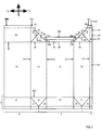
- Fig 1 is a blank in accordance with the invention showing the panels and flaps adapted to be folded and sealed to form a package in accordance with the invention.
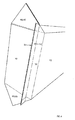
- Fig 2 shows in perspective from above the blank or package in a state where the blank has been folded to form a tube with an open top end.
- Fig 3 shows in perspective from above the blank or package in a state where the top panels and associated flaps has begun to be folded.
- Fig 4 shows in perspective from above the blank or package in state where the flaps and sealing areas are sealed but the package has not yet received its final shape.
- Fig 5 shows the final package provided with an opening device.
- the detailed description will refer to the blank or to the package dependent upon which term will give the best understanding.
- the blank discussed is an intermediate product for the forming of the package.
- the blank comprises a front panel 10, a back panel 12 and two side panels 14, 16.
- the blank further comprises a longitudinal sealing flap 18 extending along one of the side panels 16.
- the front panel 10 and the first side panel 14 are joined by a crease line 11, the first side panel 14 and the back panel 12 are joined by a crease line 13, the back panel 12 and the second side panel 16 are joined by a crease line 15, and the second side panel 16 and the longitudinal sealing flap 18 are joined by a crease line 18.
- the front panel 10, the back panel 12 and the side panels 14, 16 are adapted to be mutually folded about the crease lines 11, 13, and 15 to form a tubular container body.
- the sealing flap 18 is foldable about the crease line 17 and is sealable to the front panel 10. The outside of the sealing flap 18 is sealed to the inside of the front panel 10.
- the blank is provided with a continuous band of panels defined by a number of crease lines.
- the sealing areas a and b are adapted to abut each other, inside to inside and thereby form a so-called sealing fin.
- the triangular areas 21, 22 and 23 formed in the area forming and extension of the first side panel are adapted to be folded such that the smaller triangular areas 21 and 23 are folded back onto the larger triangular area 22. Thereby a triangular lug of the closed container is formed. This lug may be folded about the crease line 22a between the side panel 14 and the triangular area 22 to abut and to be sealed to the bottom of the package.
- the triangular areas 24, 25, 26 formed in the area forming an extension of the second side panel 16 will be folded to form a lug which in turn is folded and sealed to the bottom of the package.
- the bottom panels 27 and 28 will be folded towards each other such that the sealing areas a and b abut each other.
- the two bottom panels 27 and 28 will each occupy half of the bottom of the package. This bottom forming method will not be discussed in more detail since it is well-known in the art to form a bottom of a package using this continuous band of panels defined by a number of crease lines.
- the blank further comprises a first top panel 40 formed by an extension of the front panel 10 in a longitudinal direction L.
- the first top panel 40 is foldable in relation to the front panel 10 about a crease line 31 between the front panel 10 and the first top panel 30.
- a second top panel 50 is formed by an extension of the back panel 12 in the longitudinal direction L.
- the second top panel 50 is foldable in relation to the back panel 12 about a crease line 51 between the back panel 12 and the second top panel 50.
- the blank further comprises a first set of two flaps 40, 60, each formed by an extension of the respective side panel 14, 16.
- the flaps 40, 60 are foldable about a respective crease line 41, 61 between the flaps 40, 60 and respective side panel 14, 16.
- the blank further comprises a second set of two flaps 45, 65, each formed by an extension of the top panel 30.
- one of the flaps 45 is formed as a true, physical extension of the top panel 30 whereas the other flap 65 is formed as an imaginary, geometrical extension of the top panel 30.
- the sealing area 19 being an extension of the sealing flap 18 in the longitudinal direction L will form part 30' of the first top panel 30 when the blank is folded to form an tubular container body with an open end as shown in fig 2. In this position the second flap 65 will also become physical extension of the top panel 30.
- the flaps 45, 65 would have been physical extensions of the top panel 30 already as a blank and the imaginary extension 30' of the top panel 30 would not be present in the blank.
- the flaps 45, 65 of the second set of flaps are foldable about crease lines 33, 33' in common with respective portion of the first top panel 30, 30'.
- Each of the flaps 40, 60 is associated with a respective flap 45, 65 of the second set of flaps.
- the flaps 40, 45 located in the area forming an extension of the first side panel 14 are associated with each other and the flaps 60, 65 located in the area forming an extension of the second side panel 16 are associated with each other.
- the flaps 40, 60 of the first set of flaps are separated from the respective associated flap 45, 65 of the second set of flaps by a cut line 46, 66.
- the associated flaps When formed as a package, the associated flaps are adapted to abut and to be sealed or glued to each other inside to inside (see fig 3). In order to achieve tight corners
- the first and second top panels each comprises a sealing area 32, 52 extending from respective top panel 30, 30', 50 in the longitudinal direction L.
- the sealing areas 32, 52 extend past the respective top panel 30, 30', 50 in the respective transverse directions T1, T2 and form appended sealing areas 32b, 32c, 52b, 52c extending in the transverse directions T1, T2 from the major sealing areas 32a, 32b extending from the respective top panel 30, 50 and having the same width in the transverse direction as the respective top panel 30, 50.
- flaps 40, 45; 60, 65 of the first and second sets of flaps are separated by a cut line 46; 66.
- the thus formed flaps 40, 45, 60, 65 are triangular in shape.
- the flaps 40, 60 of the first set of flaps are formed as isosceles triangles having their respective base extending along all of the top edge (in the transverse direction) of the respective side panel 14, 16.
- the flaps 45, 65 of the second set of flaps are formed as isosceles triangles having their respective base extending along all of the height of the top panel 30, 30' in the longitudinal direction L.
- the two triangles When the edges of two associated flaps 40, 45; 60, 65 are aligned as they were not cut the two triangles will form a triangle where the basis of the respective flaps will form the smaller sides of a right-angled triangle.
- the associated flaps are formed of an right-angled isosceles triangle being divided into two equal halves by a cut line 46, 66 along the height of the large right-angled isosceles triangle.
- the front panel 10, the back panel 12, and the side panels 14, 16 forms a tubular container body.
- the appended sealing areas 32b, 32c, 52b, 52c will be guided to the desired position, since they are connected to the adjacent panel or flap as viewed in the longitudinal direction L.
- the sealing areas 32b, 32c are connected to the flaps 45, 65 of the second set of flaps. It may desired to have the flaps 45, 65 following the perimeter (as in fig 2) of the container or it may be desired to have them being essentially in the same plane as the first top panel 30. In any case the sealing areas 32b, 32c will be in the same plane as the flaps 45, 65.
- the sealing areas 52b, 52c will be guided by the small triangular panels 52d, 52e connected to the sealing areas 52b, 52c, to the side panels 14, 16 and to the flaps 40, 60 of the first set of flaps. Thereby the flaps 40, 60 and the sealing areas 52b, 52c of the second top panel 50 will follow the perimeter of the container body.
- the presence of the triangular panels 52d, 52e in the corner between the three neighbouring panels or flaps; the appended sealing areas 52b, 52c of the second top panel 50, the second top panel 50, and the flaps 40, 60 of the first set of flaps are beneficial if it is desired to have a liquid tight package.
- the triangular panels 52d, 52e will provide a continuous material in the top corners at the back of the package.
- the connection between the appended sealing areas 32b, 32c and the flaps 45, 65 of the second set of flaps will provide a continuous material following the sealing fin 32, 52 out a distance from the container body.
- the cut lines 46 and 66 are not cut all the way down to the corner of the front panel 10.
- the cut lines 46, 66 are transformed into crease lines at a distance from the corner of the front panel 10.
- the lengths of the not cut but creased portions of respective the cut line 46, 66 correspond to the lengths of the appended sealing areas 32b, 32c; 52b, 52c.
- crease lines which facilitate a correct folding of the blank into the package.
- the crease lines may be formed using any suitable creasing method.
- the sealing area 52 of the second top panel 50 is refolded back on to the top panel 50; outside to outside, whereas the sealing area 32 of the first top panel 30 extends in essentially the same plane as the first top panel 30.
- the sealing areas 32, 52 will be sealed to each other; inside to inside.
- the flaps 45, 65 of the second set of flaps will initially be folded outwardly about the crease lines 33, 33' and the flaps 40, 60 of the first set of flaps will initially extend in essentially the same plane as the first top panel 30.
- the flaps 40, 45; 60, 65 will be sealed to each other; inside to inside. When the sealing areas 42, 52 and the flaps 40, 45; 60, 65 are sealed to each the package will have reached the state as shown in fig 4.
- the package is formed by folding the flaps 40, 45; 60, 65 down along the side panels 14, 16, respectively. With this folding of the flaps the sealing fin formed by the sealing areas 32, 52 will be folded and held down along the second top panel 50.
- the package is be provided with an opening device 70 located on the first top panel 30.
- the opening device 70 may be provided to the package. It is e.g. suitable to provide the blank with a through-going hole in the first top panel 30 and to add the opening device to the package when it is in the state as shown in fig 2 since it at this point is easy to get access to both sides (inside and outside) of the first top panel 30. It may be noted that since the first top panel 30 has an extension in the longitudinal direction L being larger than the corresponding extension of the second top panel 50, there is free access to the inside of the first top panel 30 also for tools requiring space larger than the space available within the perimeter of the tubular container body.
- the second top panel 50 has an extension in the longitudinal direction L being equal to the extension in the longitudinal direction L of the sealing area 52 of the second top panel 50.
- the sealing fin formed by the abutting sealing areas 32, 52 will, when folded backwardly to abut the second top panel 50, have its upper edge essentially in flush with the back panel 12 (see fig 5). It is preferred that the upper edge of the sealing fin is slightly within perimeter of the top surface in order to avoid that the sealing fin by mistake get caught e.g. by a neighbouring package.
- the package respective blank comprises a front panel 10, a back panel 12 and two side panels 14, 16 forming a tubular container body extending in a longitudinal direction L from a bottom to a top, a first top panel 30 formed by an extension of the front panel 10 in the longitudinal direction L and being folded to essentially form the top of the package, a first set of two flaps 40, 60 each formed by an extension of respective side panel 14, 16 in the longitudinal direction L, and a second set of two flaps 45, 65 extending in mutual opposing transverse directions T1, T2 which are transverse to the longitudinal direction L, each flap 45, 65 being formed by an extension of the first top panel 30 on a respective side edge of the first top panel 30.
- Gable top containers are e.g. typically formed using a slightly different approach where the triangular portions at the extension of the side panels are folded into the container body.
- the sealing fin will only have an extension along the front and back panels and the sealing areas outside the triangular flaps will be refolded within this shorter sealing fin. It may be noted that there exists still a number of other bottom sealing techniques that may be employed within the scope of the invention.
- the longitudinal cut to provide a flat laid blank may be provided at another location in the transverse direction as long as a sealing flap is provided at the cut, corresponding to sealing flap 18 and sealing area 19, along the complete height in the longitudinal direction of the panels at the cut.
- the flaps may not extend fully as triangles but may be formed as truncated triangles where the top of the triangles are cut off. This truncated configuration is indicated with dashed lines 40t, 45t, 60t, 65t in fig 1.
Landscapes
- Engineering & Computer Science (AREA)
- Mechanical Engineering (AREA)
- Cartons (AREA)
- Supplying Of Containers To The Packaging Station (AREA)
- Control And Other Processes For Unpacking Of Materials (AREA)
- Containers And Plastic Fillers For Packaging (AREA)
- Telephone Function (AREA)
Abstract
Description
- The invention relates to a package having an extended top panel. It is contemplated to use the package for wet or dry pourable food products, such as juice, milk, wine, tomato sauce, cornflakes or the like, and the basic design concept of the package is therefore adapted to make this contemplated use possible. The package may be used for other kinds of goods.
-
EP 1 172 301 discloses a sealed package for pourable food products. The package is made from a sheet packaging material and has a top wall crossed by a transverse sealing band forming a flat projecting tab folded coplanar with and onto the top wall along a fold line. An opening device is fitted to a portion of the top wall. The tab has a strip-like auxiliary portion interposed between the sealing band and the fold line, so that the area of the portion of the top wall available for the opening device is increased by the width of the auxiliary portion. It may however be noted that on the inside of the package the fold line will interfere with the available free pouring area of the opening device. The auxiliary area will only give an enlarged fastening area on the outside of the package. - Thus, there is no satisfactory solution to form a package adapted to receive a large opening device which may have a large available pouring area.
- It is an object of the invention to provide a package adapted to receive a large opening device offering a large available pouring area.
- This object has been achieved by a package comprising a front panel, a back panel and two side panels forming a tubular container body extending in a longitudinal direction from a bottom to a top, characterised in that the package further comprises a first top panel formed by an extension of the front panel in the longitudinal direction and being folded to essentially form the top of the package, a first set of two flaps, each formed by an extension of respective side panel in the longitudinal direction and being folded to be planar with respective side panel, and a second set of two flaps extending in mutual opposing transverse directions which are transverse to the longitudinal direction, each flap being formed by an extension of the top panel on a respective side edge of the first top panel and being folded to be planar with respective side panel, wherein each of the two flaps of the first set being associated with a respective flap of the second set of flaps, and wherein respective inside surface of a flap of the first set abuts an inside surface of the respective associated flap of the second set.
- With this combination of flaps and panels it is possible to form a package where all of the top panel may be used as available area for receiving an opening device. Since the flaps of the first set of flaps abut the insides of the second set of flaps, the flaps will extend outwardly of the package. The lugs formed by the mutually abutting flaps are folded downwardly to be planar with and abut the outer side of the side panels and will thereby not interfere with the available surface for the opening device. Since there is no flaps or panels extending into the package there is neither any flap or panel interfering with the free pouring area as is the case in the prior art.
- The combination of flaps and panels also makes it possible to form tight package adapted for wet or dry pourable food products such as such as juice, milk, wine, tomato sauce, cornflakes or the like. The panels and flaps are extensions of each other and they are adapted to abut each other in order to be sealed to each other.
- Furthermore, since the second set of flaps extend in the transverse directions from the first top panel the first top panel may have an extension essentially covering the complete top of the package. The flaps of the second set of flaps will still be able to secure the first top panel to the side panels when the first top panel is folded to form the top of the package.
- Preferred embodiments follow from the dependent claims.
- The package may further comprise a second top panel formed by an extension of the back panel in the longitudinal direction and being folded to partly form the top of the package together with the first top panel. This way it is easy to provide a planar top and still have a large available surface for the provision of an opening device. The second top panel preferably only extend along the top a distance being sufficient to provide a secure and tight seal to the first panel, whereas the first top panel form the major part of the top of the package.
- The first and second top panels may each comprise a sealing area extending from respective top panel in the longitudinal direction, and along and a distance past respective top panel in the transverse directions. By providing a sealing area in this manner which extends along the top panels and which has an extension slightly outside the top panels in the transverse direction it is possible to form the seal by abutting the insides of the sealing areas. This way it is e.g. possible to use a laminated packaging material with a heat sealable polymer layer on the inside. By extending the sealing area it will be possible to have it connected to the second set of panels and thereby have an automatic guidance of the sealing areas as an extension of the first top panel on the finished package. The sealing area on the second top panel will thereby be folded onto the second top panel which minimises the surface area that is lost by the introduction of the second top panel.
- The second top panel may have an extension in the longitudinal direction being equal to the extension in the longitudinal direction of the sealing area of the second top panel. With this design the sealing fin formed by the abutting sealing areas will, when folded backwardly to abut the second top panel, have its upper edge essentially in flush with the back panel. This way a maximum surface area for receiving an opening device may be formed of the first top panel and still the sealing fin will not extend past the footprint of the package. Moreover, the package will have an aesthetically attractive appearance with the no distinct lines on the top surface of the package. It is preferred that the upper edge of the sealing fin is slightly within perimeter of the top surface in order to avoid that the sealing fin by mistake get caught e.g. by a neighbouring package.
- Respective side panel may have a width extending in parallel with the transverse directions and wherein respective flap of the first set of flaps may be formed as a triangle or truncated triangle having its base extending along said width, and preferably along the whole width. By forming the flaps in this manner they will be able to make the seal at the extension of the side panels tight whereas they still make it possible to form the flaps of the second set as desired, since they will leave at least the same amount of available geometric space.
- The first top panel may have a length along the longitudinal direction before folded as a top panel and wherein respective flap of the second set of flaps may be formed as a triangle or truncated triangle having its base extending along said length, and preferably along the whole length. Similarly as for the flaps of the first set of flaps this manner of forming the flaps will make the flaps able to make the seal at the extension of the top panel tight whereas they still make it possible to form the flaps of the first set as desired, since they will leave at least the same amount of available geometric space.
- The package further comprises an opening device located on the first top panel. As mentioned above the top panels is formed in a manner that almost all of the surface area of the top of the package is available for the opening device. Further, there are no flaps or panel extending into the package, which flaps or panels otherwise would potentially interfere with the free pouring area of the opening device.
- It is an further object of the invention to provide a blank adapted to be folded into a package which is adapted to receive a large opening device offering a large available pouring area.
- This object has been achieved by a blank comprising a front panel, a back panel and two side panels adapted to form a tubular container body and thereby extend in a longitudinal direction from a bottom to a top, characterised in that the blank further comprises a first top panel formed by an extension of the front panel in the longitudinal direction and being foldable to essentially form a top of a package, a first set of two flaps, wherein a) each flap being formed by an extension of the first top panel on a respective side edge of the first top panel and being foldable in respect of the first top panel, or b) a first flap of the second set is formed by an extension of the first top panel on a side of the first top panel and a second flap of the second set is formed by an extension on a side of a complementary first top panel adapted to coincide with the first top panel as the blank is formed into a package, wherein each of the two flaps of the first set being associated with a respective flap of the second set of flaps, and wherein respective inside surface of a flap of the first set is adapted to abut an inside surface of respective associated flap of the second set.
- With this combination of flaps and panels it is possible to form a package where all of the top panel may be used as available area for receiving an opening device. Since the flaps of the first set of flaps are adapted to abut the insides of the second set of flaps, the flaps will extend outwardly of the finished package. The lugs formed by the mutually abutting flaps are foldable downwardly to be planar with and abut the outer side of the side panels and will thereby not interfere with the available surface for the opening device. Since there will be no flaps or panels extending into the finished package there is neither any flap or panel interfering with the free pouring area as is the case in the prior art.
- The combination of flaps and panels also makes it possible to form tight package adapted for wet or dry pourable food products such as such as juice, milk, wine, tomato sauce, cornflakes or the like. The panels and flaps are extensions of each other and they are adapted to abut each other in order to be sealed to each other.
- Furthermore, since the second set of flaps extend in the transverse directions from the first top panel the first top panel may have an extension essentially covering the complete top of the package. The flaps of the second set of flaps will still be able to secure the first top panel to the side panels when the first top panel is folded to form the top of the package.
- The alternative in the claim relating to the blank is called for since the invention may be introduced in different kinds of blanks being longitudinally cut at different transverse locations.
- If the longitudinal cut of the blank e.g. is located at the centre of the back panel, the flaps of the second set will be physical extensions of the top panel already as a blank.
- If the longitudinal cut of the blank e.g. is located in a longitudinal corner at the front of the package, it will be a waste of material and it will be difficult to form the package if the flaps extend in both transverse directions from the top panel. In this case the side panel adapted to connect with the cut side of the front panel will have a small longitudinal sealing flap. This small longitudinal sealing flap will extend in the longitudinal direction and form a complementary top panel. This complementary top panel will carry the second flap of the flaps in the second set. Thus one of the flaps in the second set is formed as a true, physical extension of the top panel whereas the other flap is formed as an imaginary, geometrical extension of the top panel carried by a complementary top panel which will coincide with the first top panel when the blank is formed into a package. In this position the second flap will also become physical extension of the top panel.
- Preferred embodiments follow from the dependent claims. The respective advantages achieved by respective feature of the dependent claims have been discussed in detail in respect of the corresponding features of the dependent claims related to the finished package. The same discussion apply also for the dependent claims related to the blank.
- The blank may further comprise a second top panel formed by an extension of the back panel in the longitudinal direction and being adapted to be folded to partly form the top of the package together with the first top panel.
- The first and second top panels may each comprise a sealing area extending from respective top panel in the longitudinal direction, and along and a distance past respective top panel in the respective transverse directions.
- The second top panel may have an extension in the longitudinal direction being equal to the extension in the longitudinal direction of the sealing area of the second top panel.
- Respective side panel may have a width extending in parallel with the transverse directions and wherein respective flap of the first set of flaps may be formed as a triangle or truncated triangle having its base extending along said width, and preferably along the whole width.
- The first top panel may have a length along the longitudinal direction and wherein respective flap of the second set of flaps may be formed as a triangle or truncated triangle having its base extending along said length, and preferably along the whole length.
- The invention will hereinafter be described by way of examples of presently preferred embodiments with reference to the appended schematic drawings.
- Fig 1 is a blank in accordance with the invention showing the panels and flaps adapted to be folded and sealed to form a package in accordance with the invention.
- Fig 2 shows in perspective from above the blank or package in a state where the blank has been folded to form a tube with an open top end.
- Fig 3 shows in perspective from above the blank or package in a state where the top panels and associated flaps has begun to be folded.
- Fig 4 shows in perspective from above the blank or package in state where the flaps and sealing areas are sealed but the package has not yet received its final shape.
- Fig 5 shows the final package provided with an opening device.
- The detailed description will refer to the blank or to the package dependent upon which term will give the best understanding. The blank discussed is an intermediate product for the forming of the package.
- With reference to fig 1, the blank comprises a
front panel 10, aback panel 12 and twoside panels 14, 16. The blank further comprises a longitudinal sealing flap 18 extending along one of the side panels 16. Thefront panel 10 and thefirst side panel 14 are joined by acrease line 11, thefirst side panel 14 and theback panel 12 are joined by acrease line 13, theback panel 12 and the second side panel 16 are joined by acrease line 15, and the second side panel 16 and the longitudinal sealing flap 18 are joined by a crease line 18. Thefront panel 10, theback panel 12 and theside panels 14, 16 are adapted to be mutually folded about the crease lines 11, 13, and 15 to form a tubular container body. The sealing flap 18 is foldable about thecrease line 17 and is sealable to thefront panel 10. The outside of the sealing flap 18 is sealed to the inside of thefront panel 10. - At the bottom area A, the blank is provided with a continuous band of panels defined by a number of crease lines. The sealing areas a and b are adapted to abut each other, inside to inside and thereby form a so-called sealing fin. The
triangular areas triangular areas triangular area 22. Thereby a triangular lug of the closed container is formed. This lug may be folded about thecrease line 22a between theside panel 14 and thetriangular area 22 to abut and to be sealed to the bottom of the package. Similarly thetriangular areas bottom panels bottom panels - The blank further comprises a first
top panel 40 formed by an extension of thefront panel 10 in a longitudinal direction L. The firsttop panel 40 is foldable in relation to thefront panel 10 about acrease line 31 between thefront panel 10 and the firsttop panel 30. - A second
top panel 50 is formed by an extension of theback panel 12 in the longitudinal direction L. The secondtop panel 50 is foldable in relation to theback panel 12 about acrease line 51 between theback panel 12 and the secondtop panel 50. - The blank further comprises a first set of two
flaps respective side panel 14, 16. Theflaps respective crease line flaps respective side panel 14, 16. - The blank further comprises a second set of two
flaps top panel 30. It may be noted that one of theflaps 45 is formed as a true, physical extension of thetop panel 30 whereas theother flap 65 is formed as an imaginary, geometrical extension of thetop panel 30. The sealingarea 19 being an extension of the sealing flap 18 in the longitudinal direction L will form part 30' of the firsttop panel 30 when the blank is folded to form an tubular container body with an open end as shown in fig 2. In this position thesecond flap 65 will also become physical extension of thetop panel 30. If the longitudinal cut of the blank would have been located at the centre of theback panel 12, theflaps top panel 30 already as a blank and the imaginary extension 30' of thetop panel 30 would not be present in the blank. Theflaps crease lines 33, 33' in common with respective portion of the firsttop panel 30, 30'. - Each of the
flaps respective flap flaps first side panel 14 are associated with each other and theflaps flaps flap cut line - When formed as a package, the associated flaps are adapted to abut and to be sealed or glued to each other inside to inside (see fig 3). In order to achieve tight corners
- The first and second top panels each comprises a sealing
area top panel areas top panel areas major sealing areas top panel top panel - As mentioned above the associated flaps 40, 45; 60, 65 of the first and second sets of flaps are separated by a
cut line 46; 66. The thus formedflaps flaps respective side panel 14, 16. Theflaps top panel 30, 30' in the longitudinal direction L. When the edges of two associatedflaps cut line - As shown in fig 2, the
front panel 10, theback panel 12, and theside panels 14, 16 forms a tubular container body. The appended sealingareas areas flaps flaps top panel 30. In any case the sealingareas flaps areas triangular panels areas side panels 14, 16 and to theflaps flaps areas top panel 50 will follow the perimeter of the container body. - The presence of the
triangular panels areas top panel 50, the secondtop panel 50, and theflaps triangular panels areas flaps fin - Moreover, in order to provide tight corners where the
front panel 10,respective side panel 14, 16 and the firsttop panel 30 form the two front upper corners of the formed package, the cut lines 46 and 66 are not cut all the way down to the corner of thefront panel 10. The cut lines 46, 66 are transformed into crease lines at a distance from the corner of thefront panel 10. The lengths of the not cut but creased portions of respective thecut line areas - It should also be noted that except the cut, outer portions of the cut lines 46 and 66 all the lines inside the contour of the blank in fig 1 are crease lines which facilitate a correct folding of the blank into the package. The crease lines may be formed using any suitable creasing method.
- With reference to fig 3, it may be noted that the sealing
area 52 of the secondtop panel 50 is refolded back on to thetop panel 50; outside to outside, whereas the sealingarea 32 of the firsttop panel 30 extends in essentially the same plane as the firsttop panel 30. The sealingareas - The
flaps flaps top panel 30. Theflaps areas 42, 52 and theflaps - Finally, the package is formed by folding the
flaps side panels 14, 16, respectively. With this folding of the flaps the sealing fin formed by the sealingareas top panel 50. - The package is be provided with an
opening device 70 located on the firsttop panel 30. There are a number of occasions during the forming of the package when theopening device 70 may be provided to the package. It is e.g. suitable to provide the blank with a through-going hole in the firsttop panel 30 and to add the opening device to the package when it is in the state as shown in fig 2 since it at this point is easy to get access to both sides (inside and outside) of the firsttop panel 30. It may be noted that since the firsttop panel 30 has an extension in the longitudinal direction L being larger than the corresponding extension of the secondtop panel 50, there is free access to the inside of the firsttop panel 30 also for tools requiring space larger than the space available within the perimeter of the tubular container body. - The second
top panel 50 has an extension in the longitudinal direction L being equal to the extension in the longitudinal direction L of the sealingarea 52 of the secondtop panel 50. With this design the sealing fin formed by theabutting sealing areas top panel 50, have its upper edge essentially in flush with the back panel 12 (see fig 5). It is preferred that the upper edge of the sealing fin is slightly within perimeter of the top surface in order to avoid that the sealing fin by mistake get caught e.g. by a neighbouring package. - In summary it may be said that the package respective blank comprises a
front panel 10, aback panel 12 and twoside panels 14, 16 forming a tubular container body extending in a longitudinal direction L from a bottom to a top, a firsttop panel 30 formed by an extension of thefront panel 10 in the longitudinal direction L and being folded to essentially form the top of the package, a first set of twoflaps respective side panel 14, 16 in the longitudinal direction L, and a second set of twoflaps flap top panel 30 on a respective side edge of the firsttop panel 30. - A person skilled in the art readily realises that several modifications and variations are possible within the scope of the invention.
- It may for example be noted that although a specific kind of bottom forming method has been disclosed several other methods may be employed. Gable top containers are e.g. typically formed using a slightly different approach where the triangular portions at the extension of the side panels are folded into the container body. The sealing fin will only have an extension along the front and back panels and the sealing areas outside the triangular flaps will be refolded within this shorter sealing fin. It may be noted that there exists still a number of other bottom sealing techniques that may be employed within the scope of the invention.
- It may also be noted that the longitudinal cut to provide a flat laid blank may be provided at another location in the transverse direction as long as a sealing flap is provided at the cut, corresponding to sealing flap 18 and sealing
area 19, along the complete height in the longitudinal direction of the panels at the cut. - It may also be noted that the flaps may not extend fully as triangles but may be formed as truncated triangles where the top of the triangles are cut off. This truncated configuration is indicated with dashed
lines
Claims (13)
- A package comprising a front panel (10), a back panel (12) and two side panels (14, 16) forming a tubular container body extending in a longitudinal direction (L) from a bottom to a top, characterised in that the package further comprises
a first top panel (30) formed by an extension of the front panel (10) in the longitudinal direction (L) and being folded to essentially form the top of the package,
a first set of two flaps (40, 60) each formed by an extension of respective side panel (14, 16) in the longitudinal direction (L) and being folded to be planar with respective side panel (14, 16) , and
a second set of two flaps (45, 65) extending in mutual opposing transverse directions (T1, T2) which are transverse to the longitudinal direction (L), each flap (45, 65) being formed by an extension of the first top panel (30) on a respective side edge of the first top panel (30) and being folded to be planar with respective side panel (14, 16),
wherein each of the two flaps (40, 60) of the first set being associated with a respective flap (40 and 45, 60 and 65) of the second set of flaps (45, 65), and
wherein respective inside surface of a flap of the first set abuts an inside surface of the respective associated flap of the second set. - A package according to claim 1, wherein the package further comprises a second top panel (50) formed by an extension of the back panel (12) in the longitudinal direction (L) and being folded to partly form the top of the package together with the first top panel (30).
- A package according to claim 2, wherein the first and second top panels (30, 50) each comprises a sealing area (32, 52) extending from respective top panel (30, 50) in the longitudinal direction (L), and along and a distance (32b, 32c, 52b, 52c) past respective top panel (30, 50) in the respective transverse directions (T1, T2).
- A package according to claim 3, wherein the second top panel (50) has an extension in the longitudinal direction (L) being equal to the extension in the longitudinal direction (L) of the sealing area (52) of the second top panel (50).
- A package according to any one of claims 1-4, wherein respective side panel (14, 16) has a width extending in parallel with said the transverse directions (T1, T2) and wherein respective flap (40, 60) of the first set of flaps is formed as a triangle or truncated triangle having its base extending along said width, and preferably along the whole width.
- A package according to any one of claims 1-5, wherein the first top panel (30) has a length along the longitudinal direction (L) before folded as a top panel and wherein respective flap (45, 65) of the second set of flaps is formed as a triangle or truncated triangle having its base extending along said length, and preferably along the whole length.
- A package according to any one of claims 1-6, wherein the package further comprises an opening device (70) located on the first top panel (30).
- A blank comprising a front panel (10), a back panel (12) and two side panels (14, 16) adapted to form a tubular container body and thereby extend in a longitudinal direction (L) from a bottom to a top, characterised in that the blank further comprises
a first top panel (30) formed by an extension of the front panel (10) in the longitudinal direction (L) and being foldable to essentially form a top of a package,
a first set of two flaps (40, 60), each formed by an extension of respective side panel (14, 16) in the longitudinal direction (L) and being foldable in respect of respective side panel (14, 16), and
a second set of two flaps (45, 65) extending in mutual opposing transverse directions (T1, T2) which are transverse to the longitudinal direction (L), whereina) each flap (45, 65) being formed by an extension of the first top panel (30) on a respective side edge of the first top panel (30) and being foldable in respect of the first top panel (30), orb) a first flap (45) of the second set is formed by an extension of the first top panel (30) on a side of the first top panel (30) and a second flap (65) of the second set is formed by an extension on a side of a complementary first top panel (30') adapted to coincide with the first top panel (30) as the blank is formed into a package,wherein each of the two flaps (40, 60) of the first set being associated with a respective flap (40 and 45, 60 and 65) of the second set of flaps (45, 65), and
wherein respective inside surface of a flap (40, 60) of the first set is adapted to abut an inside surface of respective associated flap (45, 65) of the second set. - A blank according to claim 8, wherein the blank further comprises a second top panel (50) formed by an extension of the back panel (12) in the longitudinal direction (L) and being adapted to be folded to partly form the top of the package together with the first top panel (30).
- A blank according to claim 9, wherein the first and second top panels (30, 50) each comprises a sealing area (32, 52) extending from respective top panel (30, 50) in the longitudinal direction (L), and along and a distance past (32b, 32c, 52b, 52c) respective top panel (30, 50) in the respective transverse directions (T1, T2).
- A blank according to claim 10, wherein the second top panel (50) has an extension in the longitudinal direction (L) being equal to the extension in the longitudinal direction (L) of the sealing area (52) of the second top panel (50).
- A blank according to any one of claims 8-11, wherein respective side panel (14, 16) has a width extending in parallel with the transverse directions (T1, T2) and wherein respective flap (40, 60) of the first set of flaps is formed as a triangle or truncated triangle having its base extending along said width, and preferably along the whole width.
- A blank according to any one of claims 8-12, wherein the first top panel (30) has a length along the longitudinal direction (L) and wherein respective flap (45, 65) of the second set of flaps is formed as a triangle or truncated triangle having its base extending along said length, and preferably along the whole length.
Priority Applications (9)
| Application Number | Priority Date | Filing Date | Title |
|---|---|---|---|
| AT05445096T ATE533699T1 (en) | 2005-12-21 | 2005-12-21 | PACKAGING SUITABLE TO ACCOMMODATE AN OPENING DEVICE |
| ES05445096T ES2377267T3 (en) | 2005-12-21 | 2005-12-21 | Container adapted to receive an opening device |
| PL05445096T PL1801022T3 (en) | 2005-12-21 | 2005-12-21 | Package adapted to receive an opening device |
| EP05445096A EP1801022B1 (en) | 2005-12-21 | 2005-12-21 | Package adapted to receive an opening device |
| DK05445096.0T DK1801022T3 (en) | 2005-12-21 | 2005-12-21 | Packaging intended to receive an opening device |
| CN2006800511871A CN101360655B (en) | 2005-12-21 | 2006-12-21 | Packaging adapted to receive an opening device |
| US12/096,141 US8292108B2 (en) | 2005-12-21 | 2006-12-21 | Package adapted to receive an opening device |
| PCT/EP2006/070085 WO2007071763A1 (en) | 2005-12-21 | 2006-12-21 | Package adapted to receive an opening device |
| JP2008546468A JP4896988B2 (en) | 2005-12-21 | 2006-12-21 | Package intended to accept an opening device |
Applications Claiming Priority (1)
| Application Number | Priority Date | Filing Date | Title |
|---|---|---|---|
| EP05445096A EP1801022B1 (en) | 2005-12-21 | 2005-12-21 | Package adapted to receive an opening device |
Publications (2)
| Publication Number | Publication Date |
|---|---|
| EP1801022A1 true EP1801022A1 (en) | 2007-06-27 |
| EP1801022B1 EP1801022B1 (en) | 2011-11-16 |
Family
ID=36293454
Family Applications (1)
| Application Number | Title | Priority Date | Filing Date |
|---|---|---|---|
| EP05445096A Expired - Lifetime EP1801022B1 (en) | 2005-12-21 | 2005-12-21 | Package adapted to receive an opening device |
Country Status (9)
| Country | Link |
|---|---|
| US (1) | US8292108B2 (en) |
| EP (1) | EP1801022B1 (en) |
| JP (1) | JP4896988B2 (en) |
| CN (1) | CN101360655B (en) |
| AT (1) | ATE533699T1 (en) |
| DK (1) | DK1801022T3 (en) |
| ES (1) | ES2377267T3 (en) |
| PL (1) | PL1801022T3 (en) |
| WO (1) | WO2007071763A1 (en) |
Cited By (1)
| Publication number | Priority date | Publication date | Assignee | Title |
|---|---|---|---|---|
| EP3604152A4 (en) * | 2017-03-30 | 2020-12-02 | Nippon Paper Industries Co., Ltd. | PAPER CONTAINER TO ACCEPT LIQUID CONTENT FOR REFILLING |
Families Citing this family (3)
| Publication number | Priority date | Publication date | Assignee | Title |
|---|---|---|---|---|
| ES2527928T3 (en) * | 2008-08-21 | 2015-02-02 | Ardagh Mp Group Netherlands B.V. | Cap for a boat and method for orienting said lid |
| ES2741731T3 (en) * | 2014-10-29 | 2020-02-12 | Tetra Laval Holdings & Finance | Sheet packaging material for the production of sealed containers for pourable food products |
| JP6660120B2 (en) | 2015-08-25 | 2020-03-04 | 日本製紙株式会社 | Container made of paper containing liquid contents for refilling |
Citations (5)
| Publication number | Priority date | Publication date | Assignee | Title |
|---|---|---|---|---|
| FR1262203A (en) * | 1960-07-04 | 1961-05-26 | Folding flat box | |
| US4740163A (en) * | 1983-11-02 | 1988-04-26 | James River-Norwalk, Inc. | Channel opening feature for cartons |
| US5716473A (en) * | 1993-07-02 | 1998-02-10 | International Paper | Method of making a semi-rigid cereal carton |
| US6253994B1 (en) * | 1998-05-04 | 2001-07-03 | Tetra Laval Holdings And Finance Sa | Process and apparatus for applying a closure to a packaging material |
| EP1591367A1 (en) * | 2003-01-24 | 2005-11-02 | Tetra Laval Holdings & Finance S.A. | Packaging container, and pouring plug fitted thereto |
Family Cites Families (33)
| Publication number | Priority date | Publication date | Assignee | Title |
|---|---|---|---|---|
| SE390944B (en) * | 1973-04-24 | 1977-01-31 | Ziristor Ab | PACKAGING CONTAINER |
| SE377313B (en) * | 1974-04-16 | 1975-06-30 | Ziristor Ab | |
| DE2545256C2 (en) * | 1975-10-09 | 1985-08-01 | Focke & Pfuhl, 2810 Verden | Device for producing or closing packs, in particular cuboid cigarette packs |
| JPS576334Y2 (en) * | 1977-06-08 | 1982-02-05 | ||
| JPS593975Y2 (en) * | 1979-10-24 | 1984-02-03 | 凸版印刷株式会社 | Moisture-proof container with inner bag |
| JPS5827125A (en) * | 1981-08-11 | 1983-02-17 | Nec Corp | Liquid crystal display panel |
| JPS61132224A (en) * | 1984-11-30 | 1986-06-19 | Hashimoto Forming Co Ltd | Bending equipment of molding or the like |
| JPH0318331Y2 (en) * | 1985-07-29 | 1991-04-18 | ||
| JPS62197520A (en) * | 1986-02-26 | 1987-09-01 | Kumagai Gumi Ltd | Stabilization of cut ground |
| JPS62197520U (en) * | 1986-06-05 | 1987-12-16 | ||
| JPS6414622A (en) * | 1987-07-08 | 1989-01-18 | Fuji Electric Co Ltd | Mixed gas calory control system |
| US4813546A (en) * | 1988-06-15 | 1989-03-21 | International Paper Company | Opening arrangement for gable top container |
| JPH0415608Y2 (en) * | 1988-09-20 | 1992-04-08 | ||
| JP3055785B2 (en) * | 1989-08-23 | 2000-06-26 | オリンパス光学工業株式会社 | Imaging optical system |
| JPH0390822A (en) * | 1989-09-04 | 1991-04-16 | Toshiba Corp | Plant data output device |
| JPH03111925A (en) * | 1989-09-26 | 1991-05-13 | Fuji Xerox Co Ltd | Method for detecting movement of speckle pattern and position specifying device using the same |
| JPH0378716U (en) * | 1989-12-02 | 1991-08-09 | ||
| JPH03111925U (en) * | 1990-03-02 | 1991-11-15 | ||
| US5014854A (en) * | 1990-07-05 | 1991-05-14 | Champion International Corporation | Easy opening gable top carton and blank therefor |
| SE502399C2 (en) * | 1991-02-14 | 1995-10-16 | Tetra Laval Holdings & Finance | Packaging container provided with opening instructions |
| JP3057902B2 (en) * | 1992-05-28 | 2000-07-04 | 凸版印刷株式会社 | Top sealing method of flat top type liquid paper container with spout |
| JP3724651B2 (en) * | 1994-02-07 | 2005-12-07 | 大日本印刷株式会社 | Box type container with inner bag |
| JPH10147335A (en) * | 1996-11-13 | 1998-06-02 | Dainippon Printing Co Ltd | Liquid paper container for pump dispense |
| JP2605810Y2 (en) * | 1997-04-23 | 2000-08-21 | 大日本印刷株式会社 | Blank board for paper container |
| FR2796041B1 (en) * | 1999-07-09 | 2002-02-01 | Oreal | REINFORCED CLOSURE BOX |
| ATE376519T1 (en) * | 1999-08-27 | 2007-11-15 | Tetra Laval Holdings & Finance | METHOD FOR ATTACHING A LOCKABLE OPENING TO A POURABLE FOOD PACKAGING |
| JP2001114251A (en) * | 1999-10-15 | 2001-04-24 | Tokihisa Masuda | Packaging container and manufacturing method thereof |
| EP1493678B1 (en) * | 2000-07-11 | 2007-09-19 | Tetra Laval Holdings & Finance SA | Sealed package for pourable food products, and relative production method |
| US7017796B2 (en) * | 2000-07-31 | 2006-03-28 | Tetra Laval Holdings & Finance S.A. | Method of manufacturing paper packaging container and paper packaging container |
| JP4127350B2 (en) * | 2001-03-01 | 2008-07-30 | 日本製紙株式会社 | Paper container |
| KR200282152Y1 (en) * | 2002-04-18 | 2002-07-22 | 문광열 | Package for storing liquid and package structure thereof |
| JP3820571B2 (en) * | 2003-01-27 | 2006-09-13 | 中越テック株式会社 | Assembled box |
| JP2005035580A (en) * | 2003-07-18 | 2005-02-10 | Dainippon Printing Co Ltd | Liquid paper container |
-
2005
- 2005-12-21 ES ES05445096T patent/ES2377267T3/en not_active Expired - Lifetime
- 2005-12-21 EP EP05445096A patent/EP1801022B1/en not_active Expired - Lifetime
- 2005-12-21 AT AT05445096T patent/ATE533699T1/en active
- 2005-12-21 PL PL05445096T patent/PL1801022T3/en unknown
- 2005-12-21 DK DK05445096.0T patent/DK1801022T3/en active
-
2006
- 2006-12-21 JP JP2008546468A patent/JP4896988B2/en not_active Expired - Fee Related
- 2006-12-21 US US12/096,141 patent/US8292108B2/en not_active Expired - Fee Related
- 2006-12-21 CN CN2006800511871A patent/CN101360655B/en not_active Expired - Fee Related
- 2006-12-21 WO PCT/EP2006/070085 patent/WO2007071763A1/en not_active Ceased
Patent Citations (5)
| Publication number | Priority date | Publication date | Assignee | Title |
|---|---|---|---|---|
| FR1262203A (en) * | 1960-07-04 | 1961-05-26 | Folding flat box | |
| US4740163A (en) * | 1983-11-02 | 1988-04-26 | James River-Norwalk, Inc. | Channel opening feature for cartons |
| US5716473A (en) * | 1993-07-02 | 1998-02-10 | International Paper | Method of making a semi-rigid cereal carton |
| US6253994B1 (en) * | 1998-05-04 | 2001-07-03 | Tetra Laval Holdings And Finance Sa | Process and apparatus for applying a closure to a packaging material |
| EP1591367A1 (en) * | 2003-01-24 | 2005-11-02 | Tetra Laval Holdings & Finance S.A. | Packaging container, and pouring plug fitted thereto |
Cited By (1)
| Publication number | Priority date | Publication date | Assignee | Title |
|---|---|---|---|---|
| EP3604152A4 (en) * | 2017-03-30 | 2020-12-02 | Nippon Paper Industries Co., Ltd. | PAPER CONTAINER TO ACCEPT LIQUID CONTENT FOR REFILLING |
Also Published As
| Publication number | Publication date |
|---|---|
| EP1801022B1 (en) | 2011-11-16 |
| US8292108B2 (en) | 2012-10-23 |
| JP2009520652A (en) | 2009-05-28 |
| WO2007071763A1 (en) | 2007-06-28 |
| PL1801022T3 (en) | 2012-04-30 |
| DK1801022T3 (en) | 2012-02-13 |
| CN101360655B (en) | 2010-12-22 |
| JP4896988B2 (en) | 2012-03-14 |
| US20080272121A1 (en) | 2008-11-06 |
| ATE533699T1 (en) | 2011-12-15 |
| ES2377267T3 (en) | 2012-03-26 |
| CN101360655A (en) | 2009-02-04 |
Similar Documents
| Publication | Publication Date | Title |
|---|---|---|
| CN1777538B (en) | Carton with pour spout. | |
| US11299314B2 (en) | Package sleeve, package and method for manufacturing a package | |
| US4396144A (en) | Telescoped container | |
| US5147062A (en) | Paper pack container with internal bag for receiving fluids | |
| US20090039144A1 (en) | Folded food carton | |
| US20050051461A1 (en) | Folding carton | |
| US4673126A (en) | Moisture barrier carton with reclosable cover | |
| EP2803594B1 (en) | Carton blank, carton | |
| US4702410A (en) | Bottom design of packing containers | |
| US6520404B1 (en) | Carton, method of forming same, and carton blank | |
| AU2008249440B2 (en) | Leakproof container | |
| JPS6333785Y2 (en) | ||
| US20100025400A1 (en) | Box lid and blank therefor | |
| US4927075A (en) | Multi-piece flat top container | |
| EP1801022B1 (en) | Package adapted to receive an opening device | |
| US20210347522A1 (en) | Leak resistant feature for bliss box | |
| US6726088B2 (en) | Carton and carton blank | |
| EP0171275B1 (en) | Carton and blank therefor of polymeric material | |
| EP2189391A1 (en) | Box, for instance for a BIB package, blank for such a box, and assembly of a box and an inner bag | |
| JPH01167046A (en) | Flat top end cover for liquid vessel | |
| US4557415A (en) | Ice cream carton | |
| JPS6328106Y2 (en) | ||
| US20190135480A1 (en) | Food scoop with sealed bottom | |
| CN215664419U (en) | Roof formula food package box | |
| JPS6311064Y2 (en) |
Legal Events
| Date | Code | Title | Description |
|---|---|---|---|
| PUAI | Public reference made under article 153(3) epc to a published international application that has entered the european phase |
Free format text: ORIGINAL CODE: 0009012 |
|
| AK | Designated contracting states |
Kind code of ref document: A1 Designated state(s): AT BE BG CH CY CZ DE DK EE ES FI FR GB GR HU IE IS IT LI LT LU LV MC NL PL PT RO SE SI SK TR |
|
| AX | Request for extension of the european patent |
Extension state: AL BA HR MK YU |
|
| 17P | Request for examination filed |
Effective date: 20071207 |
|
| AKX | Designation fees paid |
Designated state(s): AT BE BG CH CY CZ DE DK EE ES FI FR GB GR HU IE IS IT LI LT LU LV MC NL PL PT RO SE SI SK TR |
|
| 17Q | First examination report despatched |
Effective date: 20100510 |
|
| GRAP | Despatch of communication of intention to grant a patent |
Free format text: ORIGINAL CODE: EPIDOSNIGR1 |
|
| GRAS | Grant fee paid |
Free format text: ORIGINAL CODE: EPIDOSNIGR3 |
|
| GRAA | (expected) grant |
Free format text: ORIGINAL CODE: 0009210 |
|
| AK | Designated contracting states |
Kind code of ref document: B1 Designated state(s): AT BE BG CH CY CZ DE DK EE ES FI FR GB GR HU IE IS IT LI LT LU LV MC NL PL PT RO SE SI SK TR |
|
| REG | Reference to a national code |
Ref country code: GB Ref legal event code: FG4D |
|
| REG | Reference to a national code |
Ref country code: CH Ref legal event code: EP |
|
| REG | Reference to a national code |
Ref country code: IE Ref legal event code: FG4D |
|
| REG | Reference to a national code |
Ref country code: DE Ref legal event code: R096 Ref document number: 602005031208 Country of ref document: DE Effective date: 20120112 |
|
| REG | Reference to a national code |
Ref country code: DK Ref legal event code: T3 |
|
| REG | Reference to a national code |
Ref country code: NL Ref legal event code: T3 |
|
| REG | Reference to a national code |
Ref country code: SE Ref legal event code: TRGR |
|
| REG | Reference to a national code |
Ref country code: ES Ref legal event code: FG2A Ref document number: 2377267 Country of ref document: ES Kind code of ref document: T3 Effective date: 20120326 |
|
| LTIE | Lt: invalidation of european patent or patent extension |
Effective date: 20111116 |
|
| PG25 | Lapsed in a contracting state [announced via postgrant information from national office to epo] |
Ref country code: LT Free format text: LAPSE BECAUSE OF FAILURE TO SUBMIT A TRANSLATION OF THE DESCRIPTION OR TO PAY THE FEE WITHIN THE PRESCRIBED TIME-LIMIT Effective date: 20111116 Ref country code: IS Free format text: LAPSE BECAUSE OF FAILURE TO SUBMIT A TRANSLATION OF THE DESCRIPTION OR TO PAY THE FEE WITHIN THE PRESCRIBED TIME-LIMIT Effective date: 20120316 |
|
| REG | Reference to a national code |
Ref country code: PL Ref legal event code: T3 |
|
| PG25 | Lapsed in a contracting state [announced via postgrant information from national office to epo] |
Ref country code: BE Free format text: LAPSE BECAUSE OF FAILURE TO SUBMIT A TRANSLATION OF THE DESCRIPTION OR TO PAY THE FEE WITHIN THE PRESCRIBED TIME-LIMIT Effective date: 20111116 Ref country code: LV Free format text: LAPSE BECAUSE OF FAILURE TO SUBMIT A TRANSLATION OF THE DESCRIPTION OR TO PAY THE FEE WITHIN THE PRESCRIBED TIME-LIMIT Effective date: 20111116 Ref country code: PT Free format text: LAPSE BECAUSE OF FAILURE TO SUBMIT A TRANSLATION OF THE DESCRIPTION OR TO PAY THE FEE WITHIN THE PRESCRIBED TIME-LIMIT Effective date: 20120316 Ref country code: SI Free format text: LAPSE BECAUSE OF FAILURE TO SUBMIT A TRANSLATION OF THE DESCRIPTION OR TO PAY THE FEE WITHIN THE PRESCRIBED TIME-LIMIT Effective date: 20111116 Ref country code: GR Free format text: LAPSE BECAUSE OF FAILURE TO SUBMIT A TRANSLATION OF THE DESCRIPTION OR TO PAY THE FEE WITHIN THE PRESCRIBED TIME-LIMIT Effective date: 20120217 |
|
| REG | Reference to a national code |
Ref country code: HU Ref legal event code: AG4A Ref document number: E013018 Country of ref document: HU |
|
| PG25 | Lapsed in a contracting state [announced via postgrant information from national office to epo] |
Ref country code: CY Free format text: LAPSE BECAUSE OF FAILURE TO SUBMIT A TRANSLATION OF THE DESCRIPTION OR TO PAY THE FEE WITHIN THE PRESCRIBED TIME-LIMIT Effective date: 20111116 |
|
| PG25 | Lapsed in a contracting state [announced via postgrant information from national office to epo] |
Ref country code: BG Free format text: LAPSE BECAUSE OF FAILURE TO SUBMIT A TRANSLATION OF THE DESCRIPTION OR TO PAY THE FEE WITHIN THE PRESCRIBED TIME-LIMIT Effective date: 20120216 Ref country code: CZ Free format text: LAPSE BECAUSE OF FAILURE TO SUBMIT A TRANSLATION OF THE DESCRIPTION OR TO PAY THE FEE WITHIN THE PRESCRIBED TIME-LIMIT Effective date: 20111116 Ref country code: EE Free format text: LAPSE BECAUSE OF FAILURE TO SUBMIT A TRANSLATION OF THE DESCRIPTION OR TO PAY THE FEE WITHIN THE PRESCRIBED TIME-LIMIT Effective date: 20111116 Ref country code: SK Free format text: LAPSE BECAUSE OF FAILURE TO SUBMIT A TRANSLATION OF THE DESCRIPTION OR TO PAY THE FEE WITHIN THE PRESCRIBED TIME-LIMIT Effective date: 20111116 Ref country code: MC Free format text: LAPSE BECAUSE OF NON-PAYMENT OF DUE FEES Effective date: 20111231 |
|
| PG25 | Lapsed in a contracting state [announced via postgrant information from national office to epo] |
Ref country code: RO Free format text: LAPSE BECAUSE OF FAILURE TO SUBMIT A TRANSLATION OF THE DESCRIPTION OR TO PAY THE FEE WITHIN THE PRESCRIBED TIME-LIMIT Effective date: 20111116 |
|
| REG | Reference to a national code |
Ref country code: AT Ref legal event code: MK05 Ref document number: 533699 Country of ref document: AT Kind code of ref document: T Effective date: 20111116 |
|
| PLBE | No opposition filed within time limit |
Free format text: ORIGINAL CODE: 0009261 |
|
| STAA | Information on the status of an ep patent application or granted ep patent |
Free format text: STATUS: NO OPPOSITION FILED WITHIN TIME LIMIT |
|
| 26N | No opposition filed |
Effective date: 20120817 |
|
| REG | Reference to a national code |
Ref country code: DE Ref legal event code: R097 Ref document number: 602005031208 Country of ref document: DE Effective date: 20120817 |
|
| PG25 | Lapsed in a contracting state [announced via postgrant information from national office to epo] |
Ref country code: AT Free format text: LAPSE BECAUSE OF FAILURE TO SUBMIT A TRANSLATION OF THE DESCRIPTION OR TO PAY THE FEE WITHIN THE PRESCRIBED TIME-LIMIT Effective date: 20111116 |
|
| PG25 | Lapsed in a contracting state [announced via postgrant information from national office to epo] |
Ref country code: LU Free format text: LAPSE BECAUSE OF NON-PAYMENT OF DUE FEES Effective date: 20111221 |
|
| PG25 | Lapsed in a contracting state [announced via postgrant information from national office to epo] |
Ref country code: TR Free format text: LAPSE BECAUSE OF FAILURE TO SUBMIT A TRANSLATION OF THE DESCRIPTION OR TO PAY THE FEE WITHIN THE PRESCRIBED TIME-LIMIT Effective date: 20111116 |
|
| REG | Reference to a national code |
Ref country code: FR Ref legal event code: PLFP Year of fee payment: 11 |
|
| REG | Reference to a national code |
Ref country code: FR Ref legal event code: PLFP Year of fee payment: 12 |
|
| REG | Reference to a national code |
Ref country code: FR Ref legal event code: PLFP Year of fee payment: 13 |
|
| PGFP | Annual fee paid to national office [announced via postgrant information from national office to epo] |
Ref country code: NL Payment date: 20181219 Year of fee payment: 14 Ref country code: HU Payment date: 20181215 Year of fee payment: 14 Ref country code: FI Payment date: 20181220 Year of fee payment: 14 Ref country code: DE Payment date: 20181210 Year of fee payment: 14 Ref country code: PL Payment date: 20181128 Year of fee payment: 14 Ref country code: IE Payment date: 20181220 Year of fee payment: 14 Ref country code: DK Payment date: 20181221 Year of fee payment: 14 Ref country code: SE Payment date: 20181219 Year of fee payment: 14 |
|
| PGFP | Annual fee paid to national office [announced via postgrant information from national office to epo] |
Ref country code: FR Payment date: 20181220 Year of fee payment: 14 Ref country code: CH Payment date: 20181218 Year of fee payment: 14 Ref country code: GB Payment date: 20181218 Year of fee payment: 14 |
|
| PGFP | Annual fee paid to national office [announced via postgrant information from national office to epo] |
Ref country code: ES Payment date: 20190124 Year of fee payment: 14 Ref country code: IT Payment date: 20181220 Year of fee payment: 14 |
|
| REG | Reference to a national code |
Ref country code: DE Ref legal event code: R119 Ref document number: 602005031208 Country of ref document: DE |
|
| REG | Reference to a national code |
Ref country code: FI Ref legal event code: MAE |
|
| REG | Reference to a national code |
Ref country code: DK Ref legal event code: EBP Effective date: 20191231 |
|
| REG | Reference to a national code |
Ref country code: SE Ref legal event code: EUG |
|
| PG25 | Lapsed in a contracting state [announced via postgrant information from national office to epo] |
Ref country code: FI Free format text: LAPSE BECAUSE OF NON-PAYMENT OF DUE FEES Effective date: 20191221 |
|
| REG | Reference to a national code |
Ref country code: CH Ref legal event code: PL |
|
| REG | Reference to a national code |
Ref country code: NL Ref legal event code: MM Effective date: 20200101 |
|
| GBPC | Gb: european patent ceased through non-payment of renewal fee |
Effective date: 20191221 |
|
| PG25 | Lapsed in a contracting state [announced via postgrant information from national office to epo] |
Ref country code: NL Free format text: LAPSE BECAUSE OF NON-PAYMENT OF DUE FEES Effective date: 20200101 |
|
| PG25 | Lapsed in a contracting state [announced via postgrant information from national office to epo] |
Ref country code: IT Free format text: LAPSE BECAUSE OF NON-PAYMENT OF DUE FEES Effective date: 20191221 Ref country code: FR Free format text: LAPSE BECAUSE OF NON-PAYMENT OF DUE FEES Effective date: 20191231 Ref country code: IE Free format text: LAPSE BECAUSE OF NON-PAYMENT OF DUE FEES Effective date: 20191221 Ref country code: SE Free format text: LAPSE BECAUSE OF NON-PAYMENT OF DUE FEES Effective date: 20191222 Ref country code: GB Free format text: LAPSE BECAUSE OF NON-PAYMENT OF DUE FEES Effective date: 20191221 Ref country code: DE Free format text: LAPSE BECAUSE OF NON-PAYMENT OF DUE FEES Effective date: 20200701 |
|
| PG25 | Lapsed in a contracting state [announced via postgrant information from national office to epo] |
Ref country code: HU Free format text: LAPSE BECAUSE OF NON-PAYMENT OF DUE FEES Effective date: 20191222 Ref country code: CH Free format text: LAPSE BECAUSE OF NON-PAYMENT OF DUE FEES Effective date: 20191231 Ref country code: LI Free format text: LAPSE BECAUSE OF NON-PAYMENT OF DUE FEES Effective date: 20191231 |
|
| PG25 | Lapsed in a contracting state [announced via postgrant information from national office to epo] |
Ref country code: DK Free format text: LAPSE BECAUSE OF NON-PAYMENT OF DUE FEES Effective date: 20191231 |
|
| REG | Reference to a national code |
Ref country code: ES Ref legal event code: FD2A Effective date: 20210525 |
|
| PG25 | Lapsed in a contracting state [announced via postgrant information from national office to epo] |
Ref country code: ES Free format text: LAPSE BECAUSE OF NON-PAYMENT OF DUE FEES Effective date: 20191222 Ref country code: PL Free format text: LAPSE BECAUSE OF NON-PAYMENT OF DUE FEES Effective date: 20191221 |