EP1800703A1 - Blood dialyzing apparatus - Google Patents
Blood dialyzing apparatus Download PDFInfo
- Publication number
- EP1800703A1 EP1800703A1 EP05781501A EP05781501A EP1800703A1 EP 1800703 A1 EP1800703 A1 EP 1800703A1 EP 05781501 A EP05781501 A EP 05781501A EP 05781501 A EP05781501 A EP 05781501A EP 1800703 A1 EP1800703 A1 EP 1800703A1
- Authority
- EP
- European Patent Office
- Prior art keywords
- blood
- blood circuit
- needle
- dialysate
- voltage
- Prior art date
- Legal status (The legal status is an assumption and is not a legal conclusion. Google has not performed a legal analysis and makes no representation as to the accuracy of the status listed.)
- Granted
Links
Images

Classifications
-
- A—HUMAN NECESSITIES
- A61—MEDICAL OR VETERINARY SCIENCE; HYGIENE
- A61M—DEVICES FOR INTRODUCING MEDIA INTO, OR ONTO, THE BODY; DEVICES FOR TRANSDUCING BODY MEDIA OR FOR TAKING MEDIA FROM THE BODY; DEVICES FOR PRODUCING OR ENDING SLEEP OR STUPOR
- A61M1/00—Suction or pumping devices for medical purposes; Devices for carrying-off, for treatment of, or for carrying-over, body-liquids; Drainage systems
- A61M1/14—Dialysis systems; Artificial kidneys; Blood oxygenators ; Reciprocating systems for treatment of body fluids, e.g. single needle systems for hemofiltration or pheresis
-
- A—HUMAN NECESSITIES
- A61—MEDICAL OR VETERINARY SCIENCE; HYGIENE
- A61M—DEVICES FOR INTRODUCING MEDIA INTO, OR ONTO, THE BODY; DEVICES FOR TRANSDUCING BODY MEDIA OR FOR TAKING MEDIA FROM THE BODY; DEVICES FOR PRODUCING OR ENDING SLEEP OR STUPOR
- A61M1/00—Suction or pumping devices for medical purposes; Devices for carrying-off, for treatment of, or for carrying-over, body-liquids; Drainage systems
- A61M1/36—Other treatment of blood in a by-pass of the natural circulatory system, e.g. temperature adaptation, irradiation ; Extra-corporeal blood circuits
- A61M1/3621—Extra-corporeal blood circuits
- A61M1/3653—Interfaces between patient blood circulation and extra-corporal blood circuit
- A61M1/3656—Monitoring patency or flow at connection sites; Detecting disconnections
-
- A—HUMAN NECESSITIES
- A61—MEDICAL OR VETERINARY SCIENCE; HYGIENE
- A61M—DEVICES FOR INTRODUCING MEDIA INTO, OR ONTO, THE BODY; DEVICES FOR TRANSDUCING BODY MEDIA OR FOR TAKING MEDIA FROM THE BODY; DEVICES FOR PRODUCING OR ENDING SLEEP OR STUPOR
- A61M1/00—Suction or pumping devices for medical purposes; Devices for carrying-off, for treatment of, or for carrying-over, body-liquids; Drainage systems
- A61M1/36—Other treatment of blood in a by-pass of the natural circulatory system, e.g. temperature adaptation, irradiation ; Extra-corporeal blood circuits
- A61M1/3621—Extra-corporeal blood circuits
- A61M1/3669—Electrical impedance measurement of body fluids; transducers specially adapted therefor
-
- A—HUMAN NECESSITIES
- A61—MEDICAL OR VETERINARY SCIENCE; HYGIENE
- A61M—DEVICES FOR INTRODUCING MEDIA INTO, OR ONTO, THE BODY; DEVICES FOR TRANSDUCING BODY MEDIA OR FOR TAKING MEDIA FROM THE BODY; DEVICES FOR PRODUCING OR ENDING SLEEP OR STUPOR
- A61M1/00—Suction or pumping devices for medical purposes; Devices for carrying-off, for treatment of, or for carrying-over, body-liquids; Drainage systems
- A61M1/36—Other treatment of blood in a by-pass of the natural circulatory system, e.g. temperature adaptation, irradiation ; Extra-corporeal blood circuits
- A61M1/3621—Extra-corporeal blood circuits
- A61M1/367—Circuit parts not covered by the preceding subgroups of group A61M1/3621
-
- A—HUMAN NECESSITIES
- A61—MEDICAL OR VETERINARY SCIENCE; HYGIENE
- A61M—DEVICES FOR INTRODUCING MEDIA INTO, OR ONTO, THE BODY; DEVICES FOR TRANSDUCING BODY MEDIA OR FOR TAKING MEDIA FROM THE BODY; DEVICES FOR PRODUCING OR ENDING SLEEP OR STUPOR
- A61M2205/00—General characteristics of the apparatus
- A61M2205/13—General characteristics of the apparatus with means for the detection of operative contact with patient, e.g. lip sensor
Definitions
- the present invention relates to a hemodialysis device which purifies blood from a patient in extracorporeal blood circulation.
- a blood circuit including flexible tubing is used to place patient's blood in extracorporeal circulation.
- This blood circuit arrangement mainly includes an arterial blood circuit having an arterial needle at one end to collect blood from the patient and a venous blood circuit having a venous needle at one end to return the blood to the patient.
- a dialyzer between the arterial blood circuit and the venous blood circuit purifies the blood circulating extracorporeally.
- Such a dialyzer is composed of plural hollow fibers inside the dialyzer. Blood flow inside each hollow fiber and the flow of dialysate outside the hollow fibers (i.e. between an external surface of the hollow fiber and an inside surface of a dialyzer case).
- the hollow fiber has a blood purification membrane with small pores on its surface. Wastes in the blood flowing inside the hollow fiber is discharged into the dialysate after passing the blood purification membrane and the blood, without the wastes, is returned to the patient.
- a ultrafiltration pump installed inside the dialyzer to remove water from the patient's blood allows the removal of water during dialysis.
- the pressure (venous blood pressure) of patient's blood flowing in the venous blood circuit is monitored to detect if the needle has dropped out. Specifically, when the needle is detached from the patient, the needle is open to the air and the blood pressure flowing in the venous blood circuit decreases so that the dropping out of the needle from the patient can be detected by detecting the blood pressure.
- the blood pressure (venous blood pressure), which is measured by a pressure sensor, changes depending on a number of factors, e.g., clogging in the dialyzer or a change of the condition of patient's blood during the hemodialysis treatment, so that the venous blood pressure is changeable even under normal conditions. Therefore, it is a drawback that judgment about whether the change of the pressure is due to a change of patient's position, which is normal, or due to a detachment of the venous blood needle, which is abnormal, cannot be carried out correctly.
- a hemodialysis device has voltage adding means (the voltage generator in the patent) for adding a voltage to the blood flowing in the blood circuit by adding a voltage between two electrodes, measuring means (the detector in the patent) for measuring a voltage difference at two positions according to the voltage added by the voltage adding means, and monitoring means (the calculation means in the patent) for obtaining the voltage difference by comparing the values measured by two measuring means.
- voltage adding means the voltage generator in the patent
- measuring means the detector in the patent
- monitoring means the calculation means in the patent
- the present invention provides a hemodialysis device in which a detachment of the needle from the patient who is taking a hemodialysis treatment can be accurately monitored by monitoring the voltage difference at a predetermined position while a voltage is added to the blood flowing in the blood circuit. Also, the increase of the production cost of the blood circuit which is disposable can be suppressed.
- the present invention provides a hemodialysis device including a blood circuit having an arterial blood circuit and a venous blood circuit which circulates extracorporeally the blood collected from the patient, a blood pump disposed in the arterial blood circuit, a blood purification device that is connected between the arterial blood circuit and the venous blood circuit and that purifies the blood flowing in the blood circuit, a main body having a dialysate inlet line and a dialysate outlet line having an inlet and outlet, respectively, dialysate to and from the blood purification device, a voltage adding means having two electrodes that apply voltage to the blood flowing in the blood circuit between these electrodes, a measuring means detecting electric potentials where at least two positions where the voltage is added by the voltage adding means, and a monitoring means calculating the electric potential by comparing each electric potential detected by the measuring means and monitoring a detachment of the arterial blood needle or of the venous blood needle from the patient.
- One electrode of the voltage adding means is disposed between the arterial blood needle in the arterial blood circuit, and the
- the present invention also provides a hemodialysis device in which at least one of the measuring means measures an electric potential of one of the electrodes in the voltage adding means.
- the present invention provides the hemodialysis device in which the voltage adding means or the measuring means directly contacts the blood or the dialysate to add the voltage or to detect the electric potential.
- the present invention also provides the hemodialysis device in which the monitoring means calculates the electric potential by extracting a frequency component of the measured value measured by the measuring means.
- a detachment of the needle from the patient who is taking a hemodialysis treatment is monitored by monitoring the electric potential of a predetermined position while a voltage is added to the blood flowing in the blood circuit. Also, an increase of the production cost of the blood circuit which is disposable can be suppressed.
- a connection part of the measuring means and one of the electrodes of the voltage adding means can be incorporated into the same part to further suppress an increase in the production cost.
- the measuring means can detect accurately the electric potential even if the voltage added by the voltage adding means is very low. Also, the monitoring means can monitor securely the detachment of the needle.
- the monitoring means measures the electric potential by extracting a frequency component of the measured value measured by the measuring means
- the voltage added by the voltage adding means can be decreased and an accuracy of detection by the measuring means can be increased.
- the hemodialysis device is a device to purify the patient's blood by extracorporeal circulation and is applied to a dialyzer which is used for hemodialysis treatment.
- the dialyzer includes, as shown in Fig. 1, blood circuit attached dialyzer 2, which is a blood purification device, and hemodialysis device main body 6 for supplying dialysate to dialyzer 2 and removing water.
- Blood circuit 1 includes mainly, as shown the same figure, arterial blood circuit 1 a and venous blood circuit 1b, which are made from flexible tubing.
- Dialyzer 2 is installed between arterial blood circuit 1a and venous blood circuit 1b.
- Arterial needle a is attached to the end of arterial blood circuit 1a and peristaltic blood pump 3, and venous needle b is attached to the end of venous blood circuit 1b, and drip chamber 4 for removing bubbles is attached in the middle of venous blood circuit 1b.
- peristaltic blood pump 3 When peristaltic blood pump 3 is driven while arterial needle a and venous needle b are provided to the patient, the blood of the patient flows through arterial blood circuit 1a and into dialyzer 2 which purifies the blood. The purified blood returns to the patient through venous blood circuit 1b after air bubbles are removed in drip chamber 4. Thus, the blood of the patient is purified by dialyzer 2 while extracorporeally circulating through blood circuit 1.
- Dialysate inlet and outlet lines L1 and L2 extend from hemodialysis device main body 6.
- the dialyzer 2 includes multiple hollow fibers.
- the blood flows inside the hollow fibers, and the dialysate flows between the outside surface of the hollow fibers and the inside surface of the dialyzer case.
- the hollow fibers include many micropores that are located in the outside and the inside surface of the hollow fiber membrane, and through which waste products in the blood are dialyzed to the dialysate.
- one electrode 5a is attached between arterial needle a and peristaltic blood pump 3 in arterial blood circuit 1a
- another electrode 5b is attached to dialysate inlet line L1
- voltage adding means 5 voltage adding device
- adding a voltage to the blood flowing in blood circuit 1 is connected to these electrodes 5a, 5b.
- voltage adding means 5 voltage adding device
- the blood is partially blocked and is under a non-conductive condition by squeezing action of peristaltic blood pump 3 at the position where peristaltic blood pump 3 is disposed. Accordingly, an electric current flows in the blood and the dialysate in the circuit between one electrode 5a including arterial needle a, venous needle b, and the other electrode 5b.
- measuring means 12 for measuring an electric potential of the blood flowing in the lower stream side of drip chamber 4 in venous blood circuit 1b is installed in the same lower stream side (venous needle b side). Further, the blood and the dialysate are under a conductive condition through the membrane of dialyzer 2.
- hemodialysis device main body 6 includes duplex pump 11 connected between dialysate inlet line L1 and dialysate outlet line L2, bypass line L3 connected to dialysate inlet line L2 bypassing duplex pump 11, and ultrafiltration pump 8 connected to bypass line L3. Additionally, one end of dialysate inlet line L1 is connected to dialyzer 2 (dialysate inlet port 2c) and the other end is connected to dialysate supplier 7 which prepares the dialysate of predetermined concentration.
- dialysate outlet line L2 is connected to dialyzer 2 (at dialysate outlet port 2d).
- the other end of dialysate outlet line L2 is connected to water fluid disposal means (not shown).
- the dialysate supplied from dialysate supplier 7 passes through dialysate inlet line L1 to dialyzer 2, dialysate outlet line L2 and bypass line L3, and is let out to the water fluid disposal means.
- a heater 9 and a deaeration unit 10 are both connected to dialysate inlet line L1.
- Ultrafiltration pump 8 for concentrating the blood removes water from the blood of the patient flowing through dialyzer 2.
- the volume of dialysate let out of dialysate outlet line L2 is greater than that of dialysate introduced from dialysate inlet line L1 because duplex pump 11 is quantitative; and water is removed from the blood by the difference of the inlet and outlet volume.
- other means e.g. utilizing a balancing chamber
- Monitoring means 15 (monitoring device) including electric potential calculator 13 and comparison device 14 is disposed in hemodialysis device main body 6.
- Electric potential calculator 13 is connected to other electrode 5b and measuring device 12 through wiring H1 and H2.
- the electric potential (known in the present embodiment) at other electrode 5b is measured, which is sent to electric potential calculator 13.
- other electrode 5b functions as both voltage adding device 5 and the connection point of measuring device 12, it can suppress an increase in production cost for blood circuit 1 in comparison with another device having two measuring device without sharing functions.
- voltage adding device 5 of the present embodiment is composed of an alternator so that the measured values of other electrode 5b and measuring device 12 are changed to direct-current by a smoothing circuit at electric potential calculator 13 to obtain the electric potential between both positions. Then, the difference in electric potential is sent to comparison device 14. Comparison device 14 monitors whether the electric potential measured is changed or not by comparing it with the base value (the difference of electric potential when arterial needle a and venous needle b are nonnally attached and normal treatment is being carried out). If the measured electric potential is changed, comparison device 14 decides that a needle dropped from the patient and activates an alarm 16.
- an electric current flows in the closed circuit including both needles a and b and approximately the same electric potential as the base value.
- the circuit is blocked so that no electric current flows and the electric potential measured decreases closely to zero.
- Monitoring device 15 monitors such change of the electric potential so that a detachment of arterial needle a or venous needle b from the patient can be detected.
- alarm 16 sends a notice to medical staff by device of, e.g., a predetermined sound from a speaker, turning on or flashing an alarm light, or using a display (not shown). Further, when the electric potential is changed largely from the base value by monitoring device 15, in addition to or instead of alarm 16, peristaltic blood pump 3 can be stopped, e.g., as an interruption of the hemodialysis treatment.
- a T-tube to which the electrode and the connection point are inserted is connected at the position where these electrode and connection point contacting the blood pathway or the dialysate pathway are disposed. Accordingly, as measuring device 12 and other electrode 5b can measure an electric potential even if the voltage added by voltage adding device 5 is very small, detachment of needle a or b can be surely monitored with monitoring device 15.
- one electrode 5a is disposed between arterial needle a and peristaltic blood pump 3 in arterial blood circuit 1a and other electrode 5b is disposed in dialysate inlet line L1.
- Measuring device 12a, 12b for measuring an electric potential accompanying the voltage added by voltage adding device 5 are disposed in the lower stream side (venous needle b side) of drip chamber 4 in venous blood circuit 1b.
- one electrode 5a, other electrode 5b and measuring device 12a are disposed as in Fig. 3, and measuring device 12b is disposed in the upper stream side (arterial needle a side) of other electrode 5a in arterial blood circuit 1a.
- an electric potential measured by measuring device 12a, 12b changes in comparison with a base value (the electric potential referring to Fig. 3 decreases and the electric potential referring to Fig. 4 increases) when arterial needle a or venous needle b drops from the patient during a hemodialysis treatment.
- a base value the electric potential referring to Fig. 3 decreases and the electric potential referring to Fig. 4 increases
- an electric potential measured by measuring device 12a, 12b changes in comparison with a base value (the electric potential referring to Fig. 3 decreases and the electric potential referring to Fig. 4 increases) when arterial needle a or venous needle b drops from the patient during a hemodialysis treatment.
- two measuring device 12a, 12b are disposed on the wiring extending to other electrode 5b from voltage adding device 5, and also the wiring has resistance R having the equivalent impedance to the blood flowing in blood circuit 1.
- a composition which monitors the change of difference of electric potential by monitoring strength of a frequency component extracted by, e.g., frequency analysis and band pass filter, can be employed. According to such a composition, the voltage added by voltage adding device 5 can be decreased and accuracy of measurement can be increased.
- An electrode of the voltage adding device and a connection point of the measuring device can be a capacity coupling type (which indirectly adds a voltage by disposing electric conductive material surrounding the blood circuit) instead of the above liquid contacting type (which directly contacts the blood or the dialysate).
- a capacity coupling type which indirectly adds a voltage by disposing electric conductive material surrounding the blood circuit
- the above liquid contacting type which directly contacts the blood or the dialysate.
- electrode 5b can be disposed in dialysate inlet line L1, but instead of L1, it can be disposed in line 2.
- one electrode 5a and the measuring device 12 can be the same electrode, but also the other electrode 5b and the measuring device 12 can also be the same electrode.
- electrode 5a can act as both an electrode or the emission side of voltage adding device 5 and act as measuring device, taking a potentiometric reading.
- electrode 5b can act as a ground for the voltage adding device 5 and as a measuring device 12.
- hemodialysis device main body 6 does not house a mechanism for supplying dialysate, but it can be included in a personal-type dialyzing device which houses a mechanism for supplying dialysate.
- a hemodialysis device in which one electrode of a voltage adding device is disposed between an arterial needle and a blood pump in the arterial blood circuit and also if the other electrode is disposed in the dialysate inlet line or in the dialysate outlet line, the present invention also can be applied to such a device not withstanding having a different outer appearance or function.
Landscapes
- Health & Medical Sciences (AREA)
- Heart & Thoracic Surgery (AREA)
- Vascular Medicine (AREA)
- Life Sciences & Earth Sciences (AREA)
- Engineering & Computer Science (AREA)
- Anesthesiology (AREA)
- Biomedical Technology (AREA)
- Hematology (AREA)
- Animal Behavior & Ethology (AREA)
- General Health & Medical Sciences (AREA)
- Public Health (AREA)
- Veterinary Medicine (AREA)
- Cardiology (AREA)
- Emergency Medicine (AREA)
- Urology & Nephrology (AREA)
- External Artificial Organs (AREA)
Abstract
Description
- The present application claims priority under 35 U.S.C. §119 to
Japanese Patent Application No. 2004-301108 filed on October 15, 2004 - The present invention relates to a hemodialysis device which purifies blood from a patient in extracorporeal blood circulation.
- In general purification treatment such as hemodialysis treatment, a blood circuit including flexible tubing is used to place patient's blood in extracorporeal circulation. This blood circuit arrangement mainly includes an arterial blood circuit having an arterial needle at one end to collect blood from the patient and a venous blood circuit having a venous needle at one end to return the blood to the patient. A dialyzer between the arterial blood circuit and the venous blood circuit purifies the blood circulating extracorporeally.
- Such a dialyzer is composed of plural hollow fibers inside the dialyzer. Blood flow inside each hollow fiber and the flow of dialysate outside the hollow fibers (i.e. between an external surface of the hollow fiber and an inside surface of a dialyzer case). The hollow fiber has a blood purification membrane with small pores on its surface. Wastes in the blood flowing inside the hollow fiber is discharged into the dialysate after passing the blood purification membrane and the blood, without the wastes, is returned to the patient. Also, a ultrafiltration pump installed inside the dialyzer to remove water from the patient's blood allows the removal of water during dialysis.
- When a needle is detached from a patient to whom the needle had been attached during a hemodialysis treatment due to any reason, and especially when the arterial blood needle is detached from the patient, air is indrawn from the arterial blood needle and an air-lock is generated in the dialyzer. Also, when the venous blood needle is detached from the venous blood circuit, the patient's blood introduced from the arterial blood needle is wasted without returning to the patient. According to such failure, the pressure (venous blood pressure) of patient's blood flowing in the venous blood circuit is monitored to detect if the needle has dropped out. Specifically, when the needle is detached from the patient, the needle is open to the air and the blood pressure flowing in the venous blood circuit decreases so that the dropping out of the needle from the patient can be detected by detecting the blood pressure.
- Normally the blood pressure (venous blood pressure), which is measured by a pressure sensor, changes depending on a number of factors, e.g., clogging in the dialyzer or a change of the condition of patient's blood during the hemodialysis treatment, so that the venous blood pressure is changeable even under normal conditions. Therefore, it is a drawback that judgment about whether the change of the pressure is due to a change of patient's position, which is normal, or due to a detachment of the venous blood needle, which is abnormal, cannot be carried out correctly.
- Based on such reasoning, for example, as disclosed in
Japanese Patent Publication No. 2003-518413 - However, as both electrodes are attached to the blood circuit in the above traditional hemodialysis device, the following problems remain. Specifically, since the blood circuit should be disposed of after every hemodialysis treatment, as a so-called disposable part, and since the blood circuit has two electrodes attached, the blood circuit with two electrodes should be disposed of when the treatment is over. Accordingly, it is problematic because of high production cost. Further, as the wiring of the extracorporeal blood circuit in the traditional dialyzer is rather complex, medical staff who sets the device has to do more work or may make some wiring mistakes.
- The present invention provides a hemodialysis device in which a detachment of the needle from the patient who is taking a hemodialysis treatment can be accurately monitored by monitoring the voltage difference at a predetermined position while a voltage is added to the blood flowing in the blood circuit. Also, the increase of the production cost of the blood circuit which is disposable can be suppressed.
- The present invention provides a hemodialysis device including a blood circuit having an arterial blood circuit and a venous blood circuit which circulates extracorporeally the blood collected from the patient, a blood pump disposed in the arterial blood circuit, a blood purification device that is connected between the arterial blood circuit and the venous blood circuit and that purifies the blood flowing in the blood circuit, a main body having a dialysate inlet line and a dialysate outlet line having an inlet and outlet, respectively, dialysate to and from the blood purification device, a voltage adding means having two electrodes that apply voltage to the blood flowing in the blood circuit between these electrodes, a measuring means detecting electric potentials where at least two positions where the voltage is added by the voltage adding means, and a monitoring means calculating the electric potential by comparing each electric potential detected by the measuring means and monitoring a detachment of the arterial blood needle or of the venous blood needle from the patient. One electrode of the voltage adding means is disposed between the arterial blood needle in the arterial blood circuit, and the blood pump and the other electrode is disposed in the dialysate inlet line or in the dialysate outlet line.
- The present invention also provides a hemodialysis device in which at least one of the measuring means measures an electric potential of one of the electrodes in the voltage adding means.
- Further, the present invention provides the hemodialysis device in which the voltage adding means or the measuring means directly contacts the blood or the dialysate to add the voltage or to detect the electric potential.
- The present invention also provides the hemodialysis device in which the monitoring means calculates the electric potential by extracting a frequency component of the measured value measured by the measuring means.
- According to an embodiment of the present invention, as the other electrode is disposed in the dialysate inlet line or the dialysate outlet line of the main body of the hemodialysis device, a detachment of the needle from the patient who is taking a hemodialysis treatment is monitored by monitoring the electric potential of a predetermined position while a voltage is added to the blood flowing in the blood circuit. Also, an increase of the production cost of the blood circuit which is disposable can be suppressed.
- Further, according to an embodiment of the present invention, as at least one of the measuring means measures the electric potential of one of the electrodes in the voltage adding means, a connection part of the measuring means and one of the electrodes of the voltage adding means can be incorporated into the same part to further suppress an increase in the production cost.
- According to an embodiment of the present invention, since the voltage adding means or the measuring means directly contacts the blood or the dialysate and adds a voltage or measures an electric potential, the measuring means can detect accurately the electric potential even if the voltage added by the voltage adding means is very low. Also, the monitoring means can monitor securely the detachment of the needle.
- Further, according to an embodiment of the present invention, as the monitoring means measures the electric potential by extracting a frequency component of the measured value measured by the measuring means, the voltage added by the voltage adding means can be decreased and an accuracy of detection by the measuring means can be increased.
- The foregoing and other features of the present invention will be more readily apparent from the following detailed description and drawings of the illustrative embodiments of the invention wherein like reference numbers refer to similar elements and in which:
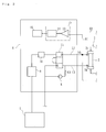
- Fig. 1 is a schematic diagram of the hemodialysis device of an embodiment of the present invention;
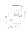
- Fig. 2 is a schematic diagram of the hemodialysis device main body which is applied to the hemodialysis device of the present invention;
- Fig. 3 is a schematic diagram of the hemodialysis device of another embodiment of the present invention;
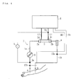
- Fig. 4 is a schematic diagram of the hemodialysis device of another embodiment of the present invention; and
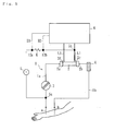
- Fig. 5 is a schematic diagram of the hemodialysis device of another embodiment of the present invention.
- The embodiments of the present invention are explained using figures. The hemodialysis device according to the present embodiments is a device to purify the patient's blood by extracorporeal circulation and is applied to a dialyzer which is used for hemodialysis treatment. The dialyzer includes, as shown in Fig. 1, blood circuit attached
dialyzer 2, which is a blood purification device, and hemodialysis devicemain body 6 for supplying dialysate todialyzer 2 and removing water.Blood circuit 1 includes mainly, as shown the same figure, arterial blood circuit 1 a andvenous blood circuit 1b, which are made from flexible tubing.Dialyzer 2 is installed between arterial blood circuit 1a andvenous blood circuit 1b. - Arterial needle a is attached to the end of arterial blood circuit 1a and
peristaltic blood pump 3, and venous needle b is attached to the end ofvenous blood circuit 1b, anddrip chamber 4 for removing bubbles is attached in the middle ofvenous blood circuit 1b. - When
peristaltic blood pump 3 is driven while arterial needle a and venous needle b are provided to the patient, the blood of the patient flows through arterial blood circuit 1a and intodialyzer 2 which purifies the blood. The purified blood returns to the patient throughvenous blood circuit 1b after air bubbles are removed indrip chamber 4. Thus, the blood of the patient is purified bydialyzer 2 while extracorporeally circulating throughblood circuit 1. - Several ports are located on a case that houses
dialyzer 2, such asblood inlet port 2a,blood outlet port 2b,dialysate inlet port 2c, anddialysate outlet port 2d.Blood inlet port 2a andblood outlet port 2b are connected to the end of arterial blood circuit 1a andvenous blood circuit 1b, respectively.Dialysate inlet port 2c anddialysate outlet port 2d are connected to dialysate inlet line L1 and dialysate outlet line L2, respectively. Dialysate inlet and outlet lines L1 and L2 extend from hemodialysis devicemain body 6. - The
dialyzer 2 includes multiple hollow fibers. The blood flows inside the hollow fibers, and the dialysate flows between the outside surface of the hollow fibers and the inside surface of the dialyzer case. The hollow fibers include many micropores that are located in the outside and the inside surface of the hollow fiber membrane, and through which waste products in the blood are dialyzed to the dialysate. - Further, one
electrode 5a is attached between arterial needle a andperistaltic blood pump 3 in arterial blood circuit 1a, anotherelectrode 5b is attached to dialysate inlet line L1, and voltage adding means 5 (voltage adding device) adding a voltage to the blood flowing inblood circuit 1 is connected to theseelectrodes peristaltic blood pump 3 at the position whereperistaltic blood pump 3 is disposed. Accordingly, an electric current flows in the blood and the dialysate in the circuit between oneelectrode 5a including arterial needle a, venous needle b, and theother electrode 5b. - Specifically, when a voltage is added by voltage adding means 5 during a hemodialysis treatment, the electric current flows in blood and dialysate flowing in arterial blood circuit 1a, arterial needle a, inside body of the patient, venous needle b,
venous blood circuit 1b, the blood pathway indialyzer 2 and the pathway of the dialysate, and dialysate inlet line L1 as a closed circuit. Further, measuring means 12 (measuring device) for measuring an electric potential of the blood flowing in the lower stream side ofdrip chamber 4 invenous blood circuit 1b is installed in the same lower stream side (venous needle b side). Further, the blood and the dialysate are under a conductive condition through the membrane ofdialyzer 2. - Further, as shown in Fig. 2, hemodialysis device
main body 6 includesduplex pump 11 connected between dialysate inlet line L1 and dialysate outlet line L2, bypass line L3 connected to dialysate inlet line L2 bypassingduplex pump 11, andultrafiltration pump 8 connected to bypass line L3. Additionally, one end of dialysate inlet line L1 is connected to dialyzer 2 (dialysate inlet port 2c) and the other end is connected todialysate supplier 7 which prepares the dialysate of predetermined concentration. - One end of dialysate outlet line L2 is connected to dialyzer 2 (at
dialysate outlet port 2d). The other end of dialysate outlet line L2 is connected to water fluid disposal means (not shown). The dialysate supplied fromdialysate supplier 7 passes through dialysate inlet line L1 todialyzer 2, dialysate outlet line L2 and bypass line L3, and is let out to the water fluid disposal means. In Fig. 2, aheater 9 and adeaeration unit 10 are both connected to dialysate inlet line L1. -
Ultrafiltration pump 8 for concentrating the blood removes water from the blood of the patient flowing throughdialyzer 2. Whenultrafiltration pump 8 is activated, the volume of dialysate let out of dialysate outlet line L2 is greater than that of dialysate introduced from dialysate inlet line L1 becauseduplex pump 11 is quantitative; and water is removed from the blood by the difference of the inlet and outlet volume. Alternatively, instead ofultrafiltration pump 8, other means (e.g. utilizing a balancing chamber) can be used to remove water from the blood of the patient. - Monitoring means 15 (monitoring device) including electric
potential calculator 13 andcomparison device 14 is disposed in hemodialysis devicemain body 6. Electricpotential calculator 13 is connected toother electrode 5b and measuringdevice 12 through wiring H1 and H2. Thus, the electric potential (known in the present embodiment) atother electrode 5b is measured, which is sent to electricpotential calculator 13. Specifically, asother electrode 5b functions as bothvoltage adding device 5 and the connection point of measuringdevice 12, it can suppress an increase in production cost forblood circuit 1 in comparison with another device having two measuring device without sharing functions. - Further,
voltage adding device 5 of the present embodiment is composed of an alternator so that the measured values ofother electrode 5b and measuringdevice 12 are changed to direct-current by a smoothing circuit at electricpotential calculator 13 to obtain the electric potential between both positions. Then, the difference in electric potential is sent tocomparison device 14.Comparison device 14 monitors whether the electric potential measured is changed or not by comparing it with the base value (the difference of electric potential when arterial needle a and venous needle b are nonnally attached and normal treatment is being carried out). If the measured electric potential is changed,comparison device 14 decides that a needle dropped from the patient and activates analarm 16. - Specifically, when arterial needle a and venous needle b are normally attached to the patient, as described, an electric current flows in the closed circuit including both needles a and b and approximately the same electric potential as the base value. When a needle is dropped from the patient, the circuit is blocked so that no electric current flows and the electric potential measured decreases closely to zero.
Monitoring device 15 monitors such change of the electric potential so that a detachment of arterial needle a or venous needle b from the patient can be detected. - When monitoring
device 15 determines that a detachment of arterial needle a or venous needle b from the patient is detected,alarm 16 sends a notice to medical staff by device of, e.g., a predetermined sound from a speaker, turning on or flashing an alarm light, or using a display (not shown). Further, when the electric potential is changed largely from the base value by monitoringdevice 15, in addition to or instead ofalarm 16,peristaltic blood pump 3 can be stopped, e.g., as an interruption of the hemodialysis treatment. - Further, the connection point of one
electrode 5a andother electrode 5b ofvoltage adding device 5 and measuringdevice 12, which directly contacts the blood flowing in arterial blood circuit 1a or the dialysate flowing in dialysate inlet line L1, adds a voltage or measures an electric potential. For example, it is preferable that a T-tube to which the electrode and the connection point are inserted is connected at the position where these electrode and connection point contacting the blood pathway or the dialysate pathway are disposed. Accordingly, as measuringdevice 12 andother electrode 5b can measure an electric potential even if the voltage added byvoltage adding device 5 is very small, detachment of needle a or b can be surely monitored withmonitoring device 15. - According to the above embodiment, not only an electric potential at a predetermined position is monitored while adding a voltage to the blood and the dialysate during a hemodialysis treatment, but also
other electrode 5b is disposed in dialysate inlet line L1 of the hemodialysis device main body. Therefore, an increase in the production cost ofblood circuit 1 which is a disposable part can be suppressed. - The present invention is not limited to the above embodiment. For example, the embodiments shown in Figs. 3 to 5 are acceptable. Specifically, referring to Fig. 3, one
electrode 5a is disposed between arterial needle a andperistaltic blood pump 3 in arterial blood circuit 1a andother electrode 5b is disposed in dialysate inlet line L1. Measuringdevice voltage adding device 5 are disposed in the lower stream side (venous needle b side) ofdrip chamber 4 invenous blood circuit 1b. Referring to Fig. 4, oneelectrode 5a,other electrode 5b and measuringdevice 12a are disposed as in Fig. 3, and measuringdevice 12b is disposed in the upper stream side (arterial needle a side) ofother electrode 5a in arterial blood circuit 1a. - According to these other embodiments, an electric potential measured by measuring
device blood circuit 1 which is a disposable part can be suppressed becauseother electrode 5b is disposed in dialysate inlet line L1 of hemodialysis devicemain body 6. - Further referring to Fig. 5, two measuring
device other electrode 5b fromvoltage adding device 5, and also the wiring has resistance R having the equivalent impedance to the blood flowing inblood circuit 1. Even using such a hemodialysis device, not only a detachment of a needle from the patient can be monitored based on the difference of voltage measured by measuringdevice blood circuit 1 which is a disposable part can be suppressed because measuringdevice other electrode 5b ofvoltage adding device 5 are not disposed inblood circuit 1. - Further according to the present embodiment, instead of changing the measured value measured by the measuring means to direct-current in electric
potential calculator 13, a composition which monitors the change of difference of electric potential by monitoring strength of a frequency component extracted by, e.g., frequency analysis and band pass filter, can be employed. According to such a composition, the voltage added byvoltage adding device 5 can be decreased and accuracy of measurement can be increased. - Further, instead of using alternate current in the voltage adding device, means for providing direct-current can be used. An electrode of the voltage adding device and a connection point of the measuring device can be a capacity coupling type (which indirectly adds a voltage by disposing electric conductive material surrounding the blood circuit) instead of the above liquid contacting type (which directly contacts the blood or the dialysate). Thus, addition of a voltage by the voltage adding device as above can be carried out continuously during the hemodialysis treatment or can be carried out intermittently. If it is carried out intermittently, the effect of suppressing anxiety of the patient due to addition of a voltage can be expected.
- Further according to the present embodiment,
other electrode 5b can be disposed in dialysate inlet line L1, but instead of L1, it can be disposed inline 2. Referring to Fig. 1, oneelectrode 5a and the measuringdevice 12 can be the same electrode, but also theother electrode 5b and the measuringdevice 12 can also be the same electrode. Thus, in an embodiment,electrode 5a can act as both an electrode or the emission side ofvoltage adding device 5 and act as measuring device, taking a potentiometric reading. Also,electrode 5b can act as a ground for thevoltage adding device 5 and as a measuringdevice 12. Further according to the present embodiment, hemodialysis devicemain body 6 does not house a mechanism for supplying dialysate, but it can be included in a personal-type dialyzing device which houses a mechanism for supplying dialysate. - If a hemodialysis device in which one electrode of a voltage adding device is disposed between an arterial needle and a blood pump in the arterial blood circuit and also if the other electrode is disposed in the dialysate inlet line or in the dialysate outlet line, the present invention also can be applied to such a device not withstanding having a different outer appearance or function.
Claims (4)
- Hemodialyzer which is characterized by one electrode of aforementioned voltage application instrument being placed between arterial needle of arterial blood circuit and the hemopump, and the other electrode being placed at either the dialysate supply line or dialysate discharge line, and which is equipped with
blood circuit consisting of arterial blood circuit and venous blood circuit where an arterial needle and venous needle is connected to the end for extracorporeal circulation of the patient's blood, and
hemopump placed on aforementioned arterial blood circuit, and
hemopurification instrument which is connected between aforementioned arterial blood circuit and venous blood circuit and purifies the blood running in such blood circuits, and
main dialyzer unit with a dialysate supply line and a dialysate discharge line for the supply and discharge of dialysate for such hemopurification instrument, and
voltage application instrument with two electrodes, applying voltage to blood running in aforementioned blood circuits between those electrodes, and
detection instrument which detects at least on two points the potential of the applied voltage by such voltage application instrument, and
monitoring instrument which compares each potential detected by such detection instrument and calculates the difference in potential, and monitors the drop-off of aforementioned arterial needle or venous needle from the patient. - Hemodialyzer as defined in claim 1, characterized by aforementioned detection instrument detecting the potential of at least either one electrode of aforementioned voltage application instrument.
- Hemodialyzer as defined in claim 1 or 2, characterized by aforementioned voltage application instrument or detection instrument applying voltage directly on or detecting potential directly in the blood or dialysate.
- Hemodialyzer as defined in either one of the claims 1 to 3, characterized by aforementioned monitoring instrument calculating the difference in potential by extracting the frequency components of the value detected by aforementioned detection instrument.
Applications Claiming Priority (2)
| Application Number | Priority Date | Filing Date | Title |
|---|---|---|---|
| JP2004301108A JP4260092B2 (en) | 2004-10-15 | 2004-10-15 | Hemodialysis machine |
| PCT/JP2005/015741 WO2006040882A1 (en) | 2004-10-15 | 2005-08-30 | Blood dialyzing apparatus |
Publications (3)
| Publication Number | Publication Date |
|---|---|
| EP1800703A1 true EP1800703A1 (en) | 2007-06-27 |
| EP1800703A4 EP1800703A4 (en) | 2009-06-03 |
| EP1800703B1 EP1800703B1 (en) | 2010-11-17 |
Family
ID=36148184
Family Applications (1)
| Application Number | Title | Priority Date | Filing Date |
|---|---|---|---|
| EP05781501A Expired - Lifetime EP1800703B1 (en) | 2004-10-15 | 2005-08-30 | Blood dialyzing apparatus |
Country Status (8)
| Country | Link |
|---|---|
| US (1) | US7537687B2 (en) |
| EP (1) | EP1800703B1 (en) |
| JP (1) | JP4260092B2 (en) |
| KR (1) | KR101147499B1 (en) |
| CN (1) | CN100528250C (en) |
| DE (1) | DE602005024846D1 (en) |
| TW (1) | TWI418376B (en) |
| WO (1) | WO2006040882A1 (en) |
Families Citing this family (40)
| Publication number | Priority date | Publication date | Assignee | Title |
|---|---|---|---|---|
| US7022098B2 (en) | 2002-04-10 | 2006-04-04 | Baxter International Inc. | Access disconnection systems and methods |
| US20040254513A1 (en) | 2002-04-10 | 2004-12-16 | Sherwin Shang | Conductive polymer materials and applications thereof including monitoring and providing effective therapy |
| US7052480B2 (en) | 2002-04-10 | 2006-05-30 | Baxter International Inc. | Access disconnection systems and methods |
| US10155082B2 (en) * | 2002-04-10 | 2018-12-18 | Baxter International Inc. | Enhanced signal detection for access disconnection systems |
| US8029454B2 (en) | 2003-11-05 | 2011-10-04 | Baxter International Inc. | High convection home hemodialysis/hemofiltration and sorbent system |
| DE102006042336A1 (en) * | 2006-09-08 | 2008-03-27 | Fresenius Medical Care Deutschland Gmbh | Device and method for monitoring access to a patient, in particular a vascular access in an extracorporeal blood treatment |
| DE102006042646B4 (en) | 2006-09-12 | 2008-11-20 | Fresenius Medical Care Deutschland Gmbh | Device and method for monitoring access to a patient, in particular a vascular access in an extracorporeal blood treatment |
| US10463778B2 (en) | 2007-02-09 | 2019-11-05 | Baxter International Inc. | Blood treatment machine having electrical heartbeat analysis |
| US8152751B2 (en) | 2007-02-09 | 2012-04-10 | Baxter International Inc. | Acoustic access disconnection systems and methods |
| US8114276B2 (en) | 2007-10-24 | 2012-02-14 | Baxter International Inc. | Personal hemodialysis system |
| US9138536B2 (en) * | 2008-04-01 | 2015-09-22 | Gambro Lundia Ab | Apparatus and a method for monitoring a vascular access |
| ES2558961T3 (en) | 2008-06-26 | 2016-02-09 | Gambro Lundia Ab | Method and device for processing a time dependent measurement signal |
| US8192388B2 (en) * | 2008-07-25 | 2012-06-05 | Baxter International Inc. | System and method for detecting access disconnection |
| US8114043B2 (en) | 2008-07-25 | 2012-02-14 | Baxter International Inc. | Electromagnetic induction access disconnect sensor |
| DE102009008885A1 (en) * | 2009-02-14 | 2010-08-26 | Fresenius Medical Care Deutschland Gmbh | Device for detecting moisture for a device for monitoring access to a patient, in particular for monitoring the vascular access in the case of extracorporeal blood treatment |
| EP2445395B1 (en) | 2009-06-26 | 2017-01-11 | Gambro Lundia AB | Devices and method for data extraction |
| WO2011049196A1 (en) * | 2009-10-23 | 2011-04-28 | 旭化成クラレメディカル株式会社 | Blood dialysis device, method for operating blood dialysis device, and water-removing system |
| EP3072545B1 (en) | 2009-10-30 | 2019-05-08 | DEKA Products Limited Partnership | Apparatus for detecting disconnection of an intravascular access device |
| US8753515B2 (en) | 2009-12-05 | 2014-06-17 | Home Dialysis Plus, Ltd. | Dialysis system with ultrafiltration control |
| US10980431B2 (en) | 2009-12-28 | 2021-04-20 | Gambro Lundia Ab | Apparatus and method for prediction of rapid symptomatic blood pressure decrease |
| US8444585B2 (en) * | 2010-01-29 | 2013-05-21 | Baxter International Inc. | Catheter needle retention and placement monitoring system and method |
| US8808218B2 (en) * | 2010-01-29 | 2014-08-19 | Baxter International Inc. | Needle placement detection and security device and method |
| US8501009B2 (en) | 2010-06-07 | 2013-08-06 | State Of Oregon Acting By And Through The State Board Of Higher Education On Behalf Of Oregon State University | Fluid purification system |
| IT1402936B1 (en) * | 2010-10-28 | 2013-09-27 | Cattini | DEVICE CONNECTED TO A MACHINE FOR THE EXTRA-PURPOSE TREATMENT OF THE BLOOD OF A PATIENT. |
| US9999717B2 (en) | 2011-05-24 | 2018-06-19 | Deka Products Limited Partnership | Systems and methods for detecting vascular access disconnection |
| CN103957960B (en) | 2011-10-07 | 2016-04-13 | 霍姆透析普拉斯有限公司 | Heat-exchange fluid for dialysis system purifies |
| CA2899720C (en) | 2013-03-20 | 2021-04-20 | Gambro Lundia Ab | Monitoring of cardiac arrest in a patient connected to an extracorporeal blood processing apparatus |
| DE102014102731A1 (en) * | 2014-02-28 | 2015-09-03 | B. Braun Avitum Ag | Apparatus and method for detecting a venous needle disconnection |
| EP3838308A1 (en) | 2014-04-29 | 2021-06-23 | Outset Medical, Inc. | Dialysis system and methods |
| CA2949987C (en) * | 2014-05-27 | 2023-01-10 | Deka Products Limited Partnership | Systems and methods for detecting vascular access disconnection |
| CN104800940A (en) * | 2015-04-03 | 2015-07-29 | 李淑刚 | Emergency treatment device for patient with heart-lung diseases |
| CN108348675B (en) * | 2015-11-26 | 2020-12-22 | 深圳市泽智知识产权有限公司 | Liquid Leak Detection Device for Medical Devices |
| US10413654B2 (en) | 2015-12-22 | 2019-09-17 | Baxter International Inc. | Access disconnection system and method using signal metrics |
| ES2908601T3 (en) | 2016-08-19 | 2022-05-03 | Outset Medical Inc | Peritoneal dialysis system and methods |
| JP6873797B2 (en) * | 2017-04-10 | 2021-05-19 | 日機装株式会社 | Blood purification device |
| DE102017114800A1 (en) * | 2017-07-03 | 2019-01-03 | Fresenius Medical Care Deutschland Gmbh | Device for detecting the state of connection |
| JP7108615B2 (en) | 2017-07-21 | 2022-07-28 | 日機装株式会社 | blood purifier |
| CN108053734B (en) * | 2018-01-25 | 2024-03-08 | 江苏农林职业技术学院 | An intravascular injection training simulator for dogs and cats limbs |
| JP2021533881A (en) | 2018-08-23 | 2021-12-09 | アウトセット・メディカル・インコーポレイテッドOutset Medical, Inc. | Dialysis system and method |
| BR112021021836A2 (en) | 2019-04-30 | 2022-01-04 | Outset Medical Inc | Methods for calculating blood pressure, for creating dialysate in a dialysis system, for measuring the percentage of rejection in a dialysis system, for collecting and analyzing blood plasma, for removing gas from an extracorporeal circuit of a dialysis system, for inferring a line pressure in an extracorporeal circuit of a dialysis system, to provide extracorporeal and intracorporeal dialysis therapy, to mount a cartridge-style patient tube set in a dialysis machine, and to prepare a dialysis machine for dialysis therapy , air removal and flow chambers, dialysis system, dialysate dispensing subsystem, single-use microbe/endotoxin filter, dialyzer, device for measuring pressure from a dialysis system, and blood tube set |
Family Cites Families (7)
| Publication number | Priority date | Publication date | Assignee | Title |
|---|---|---|---|---|
| JPS6329536U (en) * | 1986-08-12 | 1988-02-26 | ||
| DE19739099C1 (en) * | 1997-09-06 | 1999-01-28 | Fresenius Medical Care De Gmbh | Monitoring of a blood container inlet during external blood treatment |
| CH692570A5 (en) * | 1997-12-05 | 2002-08-15 | Peter F Meier | Apparatus for monitoring a catheter device. |
| IT1308687B1 (en) * | 1999-12-28 | 2002-01-09 | Gambro Dasco Spa | METHOD AND DEVICE FOR THE DETECTION OF ACCESS TO THE CARDIVASCULAR SYSTEM IN AN EXTRA-BODY BLOOD TREATMENT IN A |
| CN2440518Y (en) * | 2000-06-05 | 2001-08-01 | 高光勇 | Medical blood perfusion detoxic instrument |
| JP2002028247A (en) * | 2000-07-18 | 2002-01-29 | Japan Science & Technology Corp | Method and apparatus for sensing vein penetration by puncture needle |
| US7138088B2 (en) * | 2002-04-10 | 2006-11-21 | Baxter International Inc. | Access disconnection system and methods |
-
2004
- 2004-10-15 JP JP2004301108A patent/JP4260092B2/en not_active Expired - Fee Related
-
2005
- 2005-08-30 KR KR1020077008298A patent/KR101147499B1/en not_active Expired - Fee Related
- 2005-08-30 CN CNB2005800199635A patent/CN100528250C/en not_active Expired - Fee Related
- 2005-08-30 WO PCT/JP2005/015741 patent/WO2006040882A1/en not_active Ceased
- 2005-08-30 EP EP05781501A patent/EP1800703B1/en not_active Expired - Lifetime
- 2005-08-30 DE DE602005024846T patent/DE602005024846D1/en not_active Expired - Lifetime
- 2005-10-07 US US11/246,385 patent/US7537687B2/en active Active
- 2005-10-14 TW TW094135808A patent/TWI418376B/en not_active IP Right Cessation
Also Published As
| Publication number | Publication date |
|---|---|
| DE602005024846D1 (en) | 2010-12-30 |
| CN1968723A (en) | 2007-05-23 |
| US7537687B2 (en) | 2009-05-26 |
| TW200616682A (en) | 2006-06-01 |
| EP1800703A4 (en) | 2009-06-03 |
| CN100528250C (en) | 2009-08-19 |
| EP1800703B1 (en) | 2010-11-17 |
| JP2006110120A (en) | 2006-04-27 |
| KR101147499B1 (en) | 2012-05-21 |
| KR20070067134A (en) | 2007-06-27 |
| TWI418376B (en) | 2013-12-11 |
| US20060081517A1 (en) | 2006-04-20 |
| JP4260092B2 (en) | 2009-04-30 |
| WO2006040882A1 (en) | 2006-04-20 |
Similar Documents
| Publication | Publication Date | Title |
|---|---|---|
| EP1800703B1 (en) | Blood dialyzing apparatus | |
| US7575562B2 (en) | Blood purification device | |
| EP2918838B1 (en) | Pressure detection device for fluid flow path | |
| JP3958733B2 (en) | Blood purification equipment | |
| US10653827B2 (en) | Blood purification apparatus | |
| JP2017176847A5 (en) | ||
| JP4290106B2 (en) | Blood purification equipment | |
| WO2007058020A1 (en) | Blood purifying apparatus and method of examining the connection status of puncture needles thereof | |
| US9119922B2 (en) | Apparatus and method for identifying a tubing system for an extracorporeal blood treatment device | |
| WO2007043237A1 (en) | Blood purification apparatus and method of computing recirculation ratio thereof | |
| JP6873797B2 (en) | Blood purification device | |
| JP7184341B2 (en) | Needle removal detection method and extracorporeal blood circulation device using the method | |
| CN100548392C (en) | blood purification device | |
| JP2017006484A (en) | Blood purification apparatus and blood purification system | |
| JP4936436B2 (en) | Blood purification apparatus and method for determining mounting position of blood concentration detecting means thereof | |
| JP6736745B2 (en) | Blood purification device and blood purification system | |
| JP5237007B2 (en) | Blood purification equipment | |
| JP2016083420A (en) | Blood purification equipment | |
| WO2008065753A1 (en) | Blood purification device | |
| JP2020032216A (en) | Blood purification device and blood purification system |
Legal Events
| Date | Code | Title | Description |
|---|---|---|---|
| PUAI | Public reference made under article 153(3) epc to a published international application that has entered the european phase |
Free format text: ORIGINAL CODE: 0009012 |
|
| 17P | Request for examination filed |
Effective date: 20070302 |
|
| AK | Designated contracting states |
Kind code of ref document: A1 Designated state(s): DE FR GB IT SE |
|
| DAX | Request for extension of the european patent (deleted) | ||
| RBV | Designated contracting states (corrected) |
Designated state(s): DE FR GB IT SE |
|
| A4 | Supplementary search report drawn up and despatched |
Effective date: 20090506 |
|
| GRAP | Despatch of communication of intention to grant a patent |
Free format text: ORIGINAL CODE: EPIDOSNIGR1 |
|
| GRAS | Grant fee paid |
Free format text: ORIGINAL CODE: EPIDOSNIGR3 |
|
| GRAA | (expected) grant |
Free format text: ORIGINAL CODE: 0009210 |
|
| AK | Designated contracting states |
Kind code of ref document: B1 Designated state(s): DE FR GB IT SE |
|
| REG | Reference to a national code |
Ref country code: GB Ref legal event code: FG4D |
|
| REF | Corresponds to: |
Ref document number: 602005024846 Country of ref document: DE Date of ref document: 20101230 Kind code of ref document: P |
|
| REG | Reference to a national code |
Ref country code: SE Ref legal event code: TRGR |
|
| PLBE | No opposition filed within time limit |
Free format text: ORIGINAL CODE: 0009261 |
|
| STAA | Information on the status of an ep patent application or granted ep patent |
Free format text: STATUS: NO OPPOSITION FILED WITHIN TIME LIMIT |
|
| 26N | No opposition filed |
Effective date: 20110818 |
|
| REG | Reference to a national code |
Ref country code: DE Ref legal event code: R097 Ref document number: 602005024846 Country of ref document: DE Effective date: 20110818 |
|
| REG | Reference to a national code |
Ref country code: FR Ref legal event code: PLFP Year of fee payment: 12 |
|
| REG | Reference to a national code |
Ref country code: FR Ref legal event code: PLFP Year of fee payment: 13 |
|
| REG | Reference to a national code |
Ref country code: FR Ref legal event code: PLFP Year of fee payment: 14 |
|
| PGFP | Annual fee paid to national office [announced via postgrant information from national office to epo] |
Ref country code: SE Payment date: 20220714 Year of fee payment: 18 Ref country code: IT Payment date: 20220712 Year of fee payment: 18 Ref country code: GB Payment date: 20220707 Year of fee payment: 18 Ref country code: DE Payment date: 20220712 Year of fee payment: 18 |
|
| PGFP | Annual fee paid to national office [announced via postgrant information from national office to epo] |
Ref country code: FR Payment date: 20220709 Year of fee payment: 18 |
|
| P01 | Opt-out of the competence of the unified patent court (upc) registered |
Effective date: 20230428 |
|
| REG | Reference to a national code |
Ref country code: DE Ref legal event code: R119 Ref document number: 602005024846 Country of ref document: DE |
|
| GBPC | Gb: european patent ceased through non-payment of renewal fee |
Effective date: 20230830 |
|
| PG25 | Lapsed in a contracting state [announced via postgrant information from national office to epo] |
Ref country code: SE Free format text: LAPSE BECAUSE OF NON-PAYMENT OF DUE FEES Effective date: 20230831 |
|
| PG25 | Lapsed in a contracting state [announced via postgrant information from national office to epo] |
Ref country code: GB Free format text: LAPSE BECAUSE OF NON-PAYMENT OF DUE FEES Effective date: 20230830 |
|
| PG25 | Lapsed in a contracting state [announced via postgrant information from national office to epo] |
Ref country code: IT Free format text: LAPSE BECAUSE OF NON-PAYMENT OF DUE FEES Effective date: 20230830 Ref country code: GB Free format text: LAPSE BECAUSE OF NON-PAYMENT OF DUE FEES Effective date: 20230830 Ref country code: FR Free format text: LAPSE BECAUSE OF NON-PAYMENT OF DUE FEES Effective date: 20230831 Ref country code: DE Free format text: LAPSE BECAUSE OF NON-PAYMENT OF DUE FEES Effective date: 20240301 |