EP1800558B1 - Zip fastener - Google Patents
Zip fastener Download PDFInfo
- Publication number
- EP1800558B1 EP1800558B1 EP05450203A EP05450203A EP1800558B1 EP 1800558 B1 EP1800558 B1 EP 1800558B1 EP 05450203 A EP05450203 A EP 05450203A EP 05450203 A EP05450203 A EP 05450203A EP 1800558 B1 EP1800558 B1 EP 1800558B1
- Authority
- EP
- European Patent Office
- Prior art keywords
- zip fastener
- support tapes
- slider body
- shape
- support
- Prior art date
- Legal status (The legal status is an assumption and is not a legal conclusion. Google has not performed a legal analysis and makes no representation as to the accuracy of the status listed.)
- Not-in-force
Links
Images


Classifications
-
- A—HUMAN NECESSITIES
- A44—HABERDASHERY; JEWELLERY
- A44B—BUTTONS, PINS, BUCKLES, SLIDE FASTENERS, OR THE LIKE
- A44B19/00—Slide fasteners
- A44B19/24—Details
- A44B19/34—Stringer tapes; Flaps secured to stringers for covering the interlocking members
Definitions
- the present invention relates to a zip fastener comprising two support tapes, two rows of coupling elements, each row attached to a respective support tape, and at least one slider body having a puller attached to the said slider body, which can be formed by a thermoforming method of using heat and pressure to transform a thermoplastic substrate into a zip fastener.
- Zip fasteners are commonly used for joining together edges of two pieces of material. They may be used to provide a closable slit in a unit or may be used to join two separate pieces of material. They are widely used in the clothing industry as well as other industries, with almost any type of material.
- a conventional zip fastener is comprised of two support tapes; two rows of coupling elements, each row being attached to its own support tape; and a slider element comprised of a puller attachment used to open or close the zip fastener.
- a tunnel sometimes referred to as a garage, is created in an attempt to cover the opening at the distal end of the zip fastener as well as to hide the puller and the slider body.
- creating a tunnel or a garage is time consuming and/or undesirable in some cases and does not effectively reduce the problem of water seeping through the coupling elements. Therefore, there is a need for an improved zip fastener that further reduces the aforementioned problems and disadvantages of the conventional zip fastener.
- US 3,648,293 discloses a positioning guide and fastener combination for garments and the like, wherein the fastener is covered by folds of the support tapes.
- EP 1132 311 A2 describes a reclosable package with a zipper closure, which in a storage configuration has the zipper surrounded by a tamper-evident structure forming a pocket for enveloping at least a portion of the zipper closure. Similar reclosable bags are described in US 2003/0103690 A1 and US 2002/0015537 A1 .
- the objective of this invention is to provide a zip fastener with improved characteristics capable of reducing the problem of water seeping through the coupling elements as well as through the opening located at the distal end of the zip fastener.
- Another objective of the present invention is to provide a zip fastener that, once attached to the article, is less likely to disrupt the smoothness of the article and hides from view the unsightly puller and slider body without using a tunnel or garage.
- a zip fastener (30) according to this invention comprises first and second support tapes (35), each of which has one row of coupling elements (40) each row being attached to each support tape (35), and a slider body (45) including a puller (50).
- the support tapes (35), coupling elements (40), slider body (45) and puller (50) may be of any standard shape and structure.
- the novelty of the zip fastener (30) according to this invention lies in the shapes and structures of the two support tapes (35).
- the support tapes (35) are thermo-plasticized and portions of the first and second support tapes (35) are shaped into a U-shape, V-shape, inverted U-shape, expanded V-shape, or curve-shape by using a mold (55) and thermoforming. Shaping of the support tapes (35) through molding causes the coupling element (40) to situate either between or above the shaped support tapes (35).
- thermo plasticized first and second support tapes (35) having the coupling elements (40) engaged with the opposed row, to which the slider (45) and the puller (50) have not yet been attached are placed between two halves of the mold (55) having the desired configuration as shown in Figure 2 of which the mould is a U-shape.
- the strip of thermoplastic support tapes (35) having the coupling element (40) attached inside the mold (55) is then heated to a temperature between 80-180°C to shape or transform the support tapes (35) into the configuration corresponding to the mold.
- the strips of support tapes (35) are left to cool while still under pressure so that the desired configuration is maintained.
- the shaped support tapes (35) are removed from the mold (55).
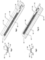
- Figure 4 shows the second embodiment of the zip fastener (30) according to this invention wherein the first and second support tapes (35) are shaped to form an inverted U-shape.
- first and second support tapes (35) are shaped to form an inverted U-shape.
- the middle portion (65) of the support tapes (35) is bent downward and the free end portion (70) of the support tapes (35) is bent outward to be on a parallel plane with the end portion (60) with the attached coupling element (40).
- the middle portion (65) and the free end portions (70) of the support tapes (35) in turn act as a support for the coupling elements (40) sitting on the top of the inverted U-shape creating a zip fastener (30) with a coupling element (40) on the support tapes (35) higher than the normally flat zip fastener.
- Figure 6 shows another embodiment of the zip fastener (30) according to this invention wherein the first and second support tapes (35) are shaped to form a U-shape.
- the end portion (60) of the first and second support tapes (35) with the attached coupling element (40) act as a base.
- the middle portion (65) of support tapes (35) is vertically lifted up and the free end portion (70) of the first and second support tapes (35) is horizontally bent to a parallel plane with the end portion (60) of which the coupling element attached.
- the U-shaped zip fastener (30) with the coupling element (40) inside the U-shape is obtained.
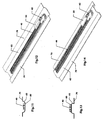
- FIG 8 and Figure 10 Further examples of additional embodiments of the zip fastener according to this invention are as shown in Figure 8 and Figure 10 wherein the zip fastener (30) is shaped into an expanded V- shape and inverted V-shape, respectively.
- Figure 12 and Figure 14 show further embodiments of the zip fastener (30) according to the present invention.
- portions of the first and second support tapes (35), including the end portion (60) of which the coupling element (40) is attached and the middle portion (65) are merged and are shaped into a curve.
- the coupling element (40) may be on the top of the curve or inside the curve similar to the U-shape.
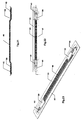
- the support tapes (35) are flat and one end or both ends of the support tapes (35) are curved downward. This is also obtained by thermoforming using the mold (55) under controlled temperature and pressure.
- the curved portion (75) of the support tapes (35) will be where the slider body (45) rests in the closed position of the zip fastener (30).
- the curved portion (75) of the zip fastener (30) accommodates at least one slider body (45) as shown in Figure 17 .
- the curved portion (75) lies beneath the surface of the article.
- the slider body (45) as well as the puller (50) is hidden from view creating a smoother look on the surface of the article.
- the opening caused when the width of the slider body obstructs the coupling elements at the distal end from engaging with each other will also be protected by the article's surface. This eliminates the need for the tunnel or garage while effectively reducing the chance of water passing through the opening.
- the embodiment where the coupling element (40) sits high on the first and second support tapes (35) such as the inverted U-shape, inverted expanded V-shape, is assembled to the article and is subsequently exposed to water the water is less likely to seep through the coupling element (40). This is because the water tends to flow away from the coupling element (40) area onto the surface adjacent to the zip fastener (30) rather than pooling as in the conventional zip fastener. This is particularly suitable for use with watertight/water-proofed articles.
- the coupling element (40) rests between the lifted portions of the first and second support tapes (35).
- the slider body (45) is assembled to form a zip fastener (30)
- the slider body (45) is housed within the lifted up portions of the first and second support tapes (35), creating a smoother look on the article's surface as the slider body (45) and the puller (50) are hidden from view, or if so desired, the entire zip fastener (30) can be hidden resulting in an even smoother look on the article's surface.
- the zip fastener (30) may be shaped into any desired configuration for various purposes and can be used with various types of material including clothing articles, canvas, etc.
Landscapes
- Slide Fasteners (AREA)
- Two-Way Televisions, Distribution Of Moving Picture Or The Like (AREA)
- Bag Frames (AREA)
Abstract
Description
- The present invention relates to a zip fastener comprising two support tapes, two rows of coupling elements, each row attached to a respective support tape, and at least one slider body having a puller attached to the said slider body, which can be formed by a thermoforming method of using heat and pressure to transform a thermoplastic substrate into a zip fastener.
- Zip fasteners are commonly used for joining together edges of two pieces of material. They may be used to provide a closable slit in a unit or may be used to join two separate pieces of material. They are widely used in the clothing industry as well as other industries, with almost any type of material.
- A conventional zip fastener is comprised of two support tapes; two rows of coupling elements, each row being attached to its own support tape; and a slider element comprised of a puller attachment used to open or close the zip fastener.
- Typically, when a conventional zip fastener is closed, there are slits between each coupling element. In addition, there is always a small opening at the distal end of the zip fastener where the width of the slider prevents the coupling elements at the distal end from locking together. When a conventional zip fastener is exposed to water, the water tends to collect around the zip fastener permitting water to seep through the coupling elements or the opening at the distal end of the zip fastener.
- In addition, in a conventional zip fastener, when the slider unites the coupling elements, the puller and top part of the slider body are clearly visible. Unless the zip fastener is designed as a decoration for an article, the zip fastener tends to disrupt the smoothness of the article's surface making it unpleasing to the eye.
- A tunnel, sometimes referred to as a garage, is created in an attempt to cover the opening at the distal end of the zip fastener as well as to hide the puller and the slider body. However, creating a tunnel or a garage is time consuming and/or undesirable in some cases and does not effectively reduce the problem of water seeping through the coupling elements. Therefore, there is a need for an improved zip fastener that further reduces the aforementioned problems and disadvantages of the conventional zip fastener.
-
US 3,648,293 discloses a positioning guide and fastener combination for garments and the like, wherein the fastener is covered by folds of the support tapes. -
EP 1132 311 A2 describes a reclosable package with a zipper closure, which in a storage configuration has the zipper surrounded by a tamper-evident structure forming a pocket for enveloping at least a portion of the zipper closure. Similar reclosable bags are described inUS 2003/0103690 A1 andUS 2002/0015537 A1 . - The objective of this invention is to provide a zip fastener with improved characteristics capable of reducing the problem of water seeping through the coupling elements as well as through the opening located at the distal end of the zip fastener.
- Another objective of the present invention is to provide a zip fastener that, once attached to the article, is less likely to disrupt the smoothness of the article and hides from view the unsightly puller and slider body without using a tunnel or garage.
- These objectives are met by a zip fastener according to one of the independent claims.
- The present invention will be better understood with reference to the detailed description and to the drawings, in which:
- Figure 1
- shows a cross sectional view of one embodiment of the zip fastener according to the present invention inside a mould.
- Figure 2
- shows a perspective view of the zip fastener of
Figure 1 inside the mould. - Figure 3
- shows a cross sectional view of one embodiment of the zip fastener shaped into an inverted U-shape.
- Figure 4
- shows a perspective view of the zip fastener of
Figure 3 . - Figure 5
- shows a cross sectional view of one embodiment of the zip fastener shaped into a U-shape.
- Figure 6
- shows a perspective view of the zip fastener of
Figure 5 . - Figure 7 a
- shows cross sectional view of one embodiment of the zip fastener shaped into an expanded V-shape.
- Figure 8
- shows a perspective view of the zip fastener of
Figure 7 . - Figure 9
- shows a cross sectional view of one embodiment of the zip fastener shaped into an inverted and expanded V-shape.
- Figure 10
- shows a perspective view of the zip fastener of
Figure 9 . - Figure 11
- shows a cross sectional view of one embodiment of the zip fastener shaped into a curve shape.
- Figure 12
- shows a perspective view of the zip fastener of
Figure 11 . - Figure 13
- shows a cross sectional view of one embodiment of the zip fastener shaped into an inverted curve shape.
- Figure 14
- shows a perspective view of the zip fastener of
Figure 13 . - Figure 15
- shows a side view of one embodiment of the zip fastener with one end curved downward and said curve accommodating one slider body.
- Figure 16
- shows a top view of the zip fastener of
Figure 15 . - Figure 17
- shows a perspective view of the zip fastener of
Figure 15 . - Figure 18
- shows a side view of one embodiment of the zip fastener with one end curved downward and said curve accommodating two slider bodies.
- Figure 19
- shows a top view of the zip fastener of
Figure 18 . - Figure 20
- shows a perspective view of the zip fastener of
Figure 18 . - Figure 21
- shows a side view of one embodiment of the zip fastener with both ends curved downward and each curve accommodating one slider body.
- Figure 22
- shows a top view of the zip fastener of
Figure 21 . - Figure 23
- shows a perspective view of the zip fastener of
Figure 21 . - It is to be understood that the present disclosure of the zip fastener described herein is a perfect exemplification of the principles of the invention and does not limit the invention to the illustrated embodiments.
- A zip fastener (30) according to this invention comprises first and second support tapes (35), each of which has one row of coupling elements (40) each row being attached to each support tape (35), and a slider body (45) including a puller (50). The support tapes (35), coupling elements (40), slider body (45) and puller (50) may be of any standard shape and structure. However, the novelty of the zip fastener (30) according to this invention lies in the shapes and structures of the two support tapes (35).
- The support tapes (35) are thermo-plasticized and portions of the first and second support tapes (35) are shaped into a U-shape, V-shape, inverted U-shape, expanded V-shape, or curve-shape by using a mold (55) and thermoforming. Shaping of the support tapes (35) through molding causes the coupling element (40) to situate either between or above the shaped support tapes (35).
- According to this invention, the thermo plasticized first and second support tapes (35) having the coupling elements (40) engaged with the opposed row, to which the slider (45) and the puller (50) have not yet been attached are placed between two halves of the mold (55) having the desired configuration as shown in
Figure 2 of which the mould is a U-shape. The strip of thermoplastic support tapes (35) having the coupling element (40) attached inside the mold (55) is then heated to a temperature between 80-180°C to shape or transform the support tapes (35) into the configuration corresponding to the mold. While still inside the mold (55), the strips of support tapes (35) are left to cool while still under pressure so that the desired configuration is maintained. Once cooled, the shaped support tapes (35) are removed from the mold (55). -
Figure 4 shows the second embodiment of the zip fastener (30) according to this invention wherein the first and second support tapes (35) are shaped to form an inverted U-shape. As shown, one end portion (60) of the first and second support tapes (35) of which the coupling element (40) sits on the top of the inverted U-shape, the middle portion (65) of the support tapes (35) is bent downward and the free end portion (70) of the support tapes (35) is bent outward to be on a parallel plane with the end portion (60) with the attached coupling element (40). As a result, the middle portion (65) and the free end portions (70) of the support tapes (35) in turn act as a support for the coupling elements (40) sitting on the top of the inverted U-shape creating a zip fastener (30) with a coupling element (40) on the support tapes (35) higher than the normally flat zip fastener. -
Figure 6 shows another embodiment of the zip fastener (30) according to this invention wherein the first and second support tapes (35) are shaped to form a U-shape. In this embodiment, using the coupling element (40) as a reference point, the end portion (60) of the first and second support tapes (35) with the attached coupling element (40) act as a base. The middle portion (65) of support tapes (35) is vertically lifted up and the free end portion (70) of the first and second support tapes (35) is horizontally bent to a parallel plane with the end portion (60) of which the coupling element attached. Thereby, the U-shaped zip fastener (30) with the coupling element (40) inside the U-shape is obtained. - Further examples of additional embodiments of the zip fastener according to this invention are as shown in
Figure 8 and Figure 10 wherein the zip fastener (30) is shaped into an expanded V- shape and inverted V-shape, respectively.Figure 12 and Figure 14 show further embodiments of the zip fastener (30) according to the present invention. In these embodiments, portions of the first and second support tapes (35), including the end portion (60) of which the coupling element (40) is attached and the middle portion (65), are merged and are shaped into a curve. The coupling element (40) may be on the top of the curve or inside the curve similar to the U-shape. - In yet another embodiment of the zip fastener (30) according to the present invention, as shown in
Figure 15 andFigure 18 the support tapes (35) are flat and one end or both ends of the support tapes (35) are curved downward. This is also obtained by thermoforming using the mold (55) under controlled temperature and pressure. When the slider (45) and the puller (50) are assembled to the strip of the support tapes (35) with the coupling element (40) attached, the curved portion (75) of the support tapes (35) will be where the slider body (45) rests in the closed position of the zip fastener (30). The curved portion (75) of the zip fastener (30) accommodates at least one slider body (45) as shown inFigure 17 . After being attached to the article, the curved portion (75) lies beneath the surface of the article. As a result, the slider body (45) as well as the puller (50) is hidden from view creating a smoother look on the surface of the article. As the slider body (45) is hidden under the surface of the article, the opening, caused when the width of the slider body obstructs the coupling elements at the distal end from engaging with each other will also be protected by the article's surface. This eliminates the need for the tunnel or garage while effectively reducing the chance of water passing through the opening. - Once the zip fastener (30) according to the present invention, particularly, the embodiment where the coupling element (40) sits high on the first and second support tapes (35) such as the inverted U-shape, inverted expanded V-shape, is assembled to the article and is subsequently exposed to water, the water is less likely to seep through the coupling element (40). This is because the water tends to flow away from the coupling element (40) area onto the surface adjacent to the zip fastener (30) rather than pooling as in the conventional zip fastener. This is particularly suitable for use with watertight/water-proofed articles. For the embodiment of which portions of the first and second support tapes (35) were lifted up, such as in the U-shape, expanded V-shape, and curve shape the coupling element (40) rests between the lifted portions of the first and second support tapes (35). Once the slider body (45) is assembled to form a zip fastener (30), the slider body (45) is housed within the lifted up portions of the first and second support tapes (35), creating a smoother look on the article's surface as the slider body (45) and the puller (50) are hidden from view, or if so desired, the entire zip fastener (30) can be hidden resulting in an even smoother look on the article's surface.
- As illustrated in the various embodiments, the zip fastener (30) according to this invention may be shaped into any desired configuration for various purposes and can be used with various types of material including clothing articles, canvas, etc.
- Other and further arrangements, variations, and embodiments for the present invention will be apparent from the forgoing disclosure and teaching and no undue limitations are to be implied there from.
Claims (5)
- A zip fastener comprising two support tapes (35), two rows of coupling elements (40), each row attached to a respective support tape, and at least one slider body (45) having a puller (50) attached to the said slider body, characterized in that the two support tapes comprise middle portions (65) bending upward from inner portions (60) of the support tapes and free-end portions (70) running on a plane parallel with said inner portions (60), to cause the two rows of coupling elements to rest between the middle portions (65) of the two support tapes.
- A zip fastener comprising two support tapes (35), two rows of coupling elements (40), each row attached to a respective support tape, and at least one slider body (45) having a puller (50) attached to the said slider body, characterized in that the two support tapes comprise middle portions (65) bending downward from inner portions (60) of the support tapes and free-end portions (70) running on a plane parallel with said inner portions (60), to cause the two rows of coupling elements to rest above the middle portions of the support tapes.
- The zip fastener according to claim 1 or claim 2 wherein the middle and inner portions of the two support tapes are shaped according to a shape chosen from the following groups of shapes: U-shape, inverted U-shape, curve shape, inverted curve shape, expanded V-shape, and inverted expanded V-shape.
- The zip fastener according to any one of claims 1 to 3 wherein at least one end of the two support tapes is curved downward, and in a closed position the curve accommodates at least one slider body.
- A zip fastener comprising two support tapes (35), two rows of coupling elements (40), each row attached to a respective support tape, and at least one slider body (45) having a puller (50) assembled to the slider body, characterized in that the two support tapes comprise a flat segment while at least one end of the two support tapes is curved downward, and in a closed position the curve accommodates at least one slider body (45).
Priority Applications (3)
| Application Number | Priority Date | Filing Date | Title |
|---|---|---|---|
| EP05450203A EP1800558B1 (en) | 2005-12-20 | 2005-12-20 | Zip fastener |
| AT05450203T ATE416645T1 (en) | 2005-12-20 | 2005-12-20 | ZIPPER |
| DE602005011652T DE602005011652D1 (en) | 2005-12-20 | 2005-12-20 | Zipper |
Applications Claiming Priority (1)
| Application Number | Priority Date | Filing Date | Title |
|---|---|---|---|
| EP05450203A EP1800558B1 (en) | 2005-12-20 | 2005-12-20 | Zip fastener |
Publications (2)
| Publication Number | Publication Date |
|---|---|
| EP1800558A1 EP1800558A1 (en) | 2007-06-27 |
| EP1800558B1 true EP1800558B1 (en) | 2008-12-10 |
Family
ID=36579252
Family Applications (1)
| Application Number | Title | Priority Date | Filing Date |
|---|---|---|---|
| EP05450203A Not-in-force EP1800558B1 (en) | 2005-12-20 | 2005-12-20 | Zip fastener |
Country Status (3)
| Country | Link |
|---|---|
| EP (1) | EP1800558B1 (en) |
| AT (1) | ATE416645T1 (en) |
| DE (1) | DE602005011652D1 (en) |
Cited By (1)
| Publication number | Priority date | Publication date | Assignee | Title |
|---|---|---|---|---|
| RU2700917C2 (en) * | 2014-02-06 | 2019-09-23 | Рафаэль ЛАДАЕВ | Sleeve of garment with partially detachable suture on zipper |
Family Cites Families (4)
| Publication number | Priority date | Publication date | Assignee | Title |
|---|---|---|---|---|
| US3648293A (en) * | 1970-02-06 | 1972-03-14 | Vera E Del Vecchio | Fastener and positioning guide therefor |
| US6360513B1 (en) * | 1999-05-11 | 2002-03-26 | Sargento Foods Inc. | Resealable bag for filling with food product(s) and method |
| JP2001335070A (en) * | 2000-02-28 | 2001-12-04 | Reynolds Consumer Prod Inc | Reclosable package having zipper closure, slider device and tamper-evident structure, and method |
| US20020094137A1 (en) * | 2001-01-16 | 2002-07-18 | Schneider John H. | Tamper evident resealable packaging |
-
2005
- 2005-12-20 DE DE602005011652T patent/DE602005011652D1/en active Active
- 2005-12-20 AT AT05450203T patent/ATE416645T1/en not_active IP Right Cessation
- 2005-12-20 EP EP05450203A patent/EP1800558B1/en not_active Not-in-force
Cited By (1)
| Publication number | Priority date | Publication date | Assignee | Title |
|---|---|---|---|---|
| RU2700917C2 (en) * | 2014-02-06 | 2019-09-23 | Рафаэль ЛАДАЕВ | Sleeve of garment with partially detachable suture on zipper |
Also Published As
| Publication number | Publication date |
|---|---|
| DE602005011652D1 (en) | 2009-01-22 |
| ATE416645T1 (en) | 2008-12-15 |
| EP1800558A1 (en) | 2007-06-27 |
Similar Documents
| Publication | Publication Date | Title |
|---|---|---|
| US9314069B2 (en) | Top stop for slider | |
| US7257868B2 (en) | Slider for concealed type slide fastener and concealed type slide fastener | |
| CN102667181B (en) | Shaft support structure, clip, and molding die for shaft support structure | |
| DE69006880T2 (en) | Zipper pull. | |
| CA2111901C (en) | Slider pull tab | |
| JP5311096B2 (en) | Zip fastener stop | |
| US4985969A (en) | Slider for slide fasteners | |
| CN102469860B (en) | Slide fastener | |
| USD442772S1 (en) | Lace cover for a shoe or similar article | |
| EP1800558B1 (en) | Zip fastener | |
| US7921526B2 (en) | Zip fastener | |
| US9307810B2 (en) | Decorated slide fastener | |
| US20090229091A1 (en) | Slide Fastener and a Slider for a Slide Fastener | |
| EP1430804B1 (en) | Concealed type slide fastener | |
| AU2005246959B2 (en) | A zip fastener | |
| US11172712B2 (en) | Garment extender | |
| JP4975312B2 (en) | fastener | |
| CN111212582A (en) | Safety slider for slide fastener | |
| US6611998B1 (en) | Closure device | |
| KR20070065649A (en) | A zip fastener | |
| US20040159570A1 (en) | Package with a flat hinge portion | |
| USD843265S1 (en) | Zipper pull tab | |
| CN218390093U (en) | Suitcase with hidden anti-theft lock set | |
| CN1985696A (en) | Slide fastener | |
| US2090367A (en) | Ornamental adjustable slide fastener |
Legal Events
| Date | Code | Title | Description |
|---|---|---|---|
| PUAI | Public reference made under article 153(3) epc to a published international application that has entered the european phase |
Free format text: ORIGINAL CODE: 0009012 |
|
| AK | Designated contracting states |
Kind code of ref document: A1 Designated state(s): AT BE BG CH CY CZ DE DK EE ES FI FR GB GR HU IE IS IT LI LT LU LV MC NL PL PT RO SE SI SK TR |
|
| AX | Request for extension of the european patent |
Extension state: AL BA HR MK YU |
|
| 17P | Request for examination filed |
Effective date: 20071217 |
|
| AKX | Designation fees paid |
Designated state(s): AT BE BG CH CY CZ DE DK EE ES FI FR GB GR HU IE IS IT LI LT LU LV MC NL PL PT RO SE SI SK TR |
|
| 17Q | First examination report despatched |
Effective date: 20080310 |
|
| GRAP | Despatch of communication of intention to grant a patent |
Free format text: ORIGINAL CODE: EPIDOSNIGR1 |
|
| GRAS | Grant fee paid |
Free format text: ORIGINAL CODE: EPIDOSNIGR3 |
|
| GRAS | Grant fee paid |
Free format text: ORIGINAL CODE: EPIDOSNIGR3 |
|
| GRAA | (expected) grant |
Free format text: ORIGINAL CODE: 0009210 |
|
| AK | Designated contracting states |
Kind code of ref document: B1 Designated state(s): AT BE BG CH CY CZ DE DK EE ES FI FR GB GR HU IE IS IT LI LT LU LV MC NL PL PT RO SE SI SK TR |
|
| REG | Reference to a national code |
Ref country code: GB Ref legal event code: FG4D |
|
| REG | Reference to a national code |
Ref country code: CH Ref legal event code: EP |
|
| REG | Reference to a national code |
Ref country code: IE Ref legal event code: FG4D |
|
| REF | Corresponds to: |
Ref document number: 602005011652 Country of ref document: DE Date of ref document: 20090122 Kind code of ref document: P |
|
| PG25 | Lapsed in a contracting state [announced via postgrant information from national office to epo] |
Ref country code: LT Free format text: LAPSE BECAUSE OF FAILURE TO SUBMIT A TRANSLATION OF THE DESCRIPTION OR TO PAY THE FEE WITHIN THE PRESCRIBED TIME-LIMIT Effective date: 20081210 |
|
| PG25 | Lapsed in a contracting state [announced via postgrant information from national office to epo] |
Ref country code: FI Free format text: LAPSE BECAUSE OF FAILURE TO SUBMIT A TRANSLATION OF THE DESCRIPTION OR TO PAY THE FEE WITHIN THE PRESCRIBED TIME-LIMIT Effective date: 20081210 Ref country code: LV Free format text: LAPSE BECAUSE OF FAILURE TO SUBMIT A TRANSLATION OF THE DESCRIPTION OR TO PAY THE FEE WITHIN THE PRESCRIBED TIME-LIMIT Effective date: 20081210 Ref country code: SI Free format text: LAPSE BECAUSE OF FAILURE TO SUBMIT A TRANSLATION OF THE DESCRIPTION OR TO PAY THE FEE WITHIN THE PRESCRIBED TIME-LIMIT Effective date: 20081210 Ref country code: PL Free format text: LAPSE BECAUSE OF FAILURE TO SUBMIT A TRANSLATION OF THE DESCRIPTION OR TO PAY THE FEE WITHIN THE PRESCRIBED TIME-LIMIT Effective date: 20081210 |
|
| PG25 | Lapsed in a contracting state [announced via postgrant information from national office to epo] |
Ref country code: RO Free format text: LAPSE BECAUSE OF FAILURE TO SUBMIT A TRANSLATION OF THE DESCRIPTION OR TO PAY THE FEE WITHIN THE PRESCRIBED TIME-LIMIT Effective date: 20081210 Ref country code: MC Free format text: LAPSE BECAUSE OF NON-PAYMENT OF DUE FEES Effective date: 20081231 Ref country code: BG Free format text: LAPSE BECAUSE OF FAILURE TO SUBMIT A TRANSLATION OF THE DESCRIPTION OR TO PAY THE FEE WITHIN THE PRESCRIBED TIME-LIMIT Effective date: 20090310 Ref country code: ES Free format text: LAPSE BECAUSE OF FAILURE TO SUBMIT A TRANSLATION OF THE DESCRIPTION OR TO PAY THE FEE WITHIN THE PRESCRIBED TIME-LIMIT Effective date: 20090321 Ref country code: EE Free format text: LAPSE BECAUSE OF FAILURE TO SUBMIT A TRANSLATION OF THE DESCRIPTION OR TO PAY THE FEE WITHIN THE PRESCRIBED TIME-LIMIT Effective date: 20081210 Ref country code: BE Free format text: LAPSE BECAUSE OF FAILURE TO SUBMIT A TRANSLATION OF THE DESCRIPTION OR TO PAY THE FEE WITHIN THE PRESCRIBED TIME-LIMIT Effective date: 20081210 |
|
| PG25 | Lapsed in a contracting state [announced via postgrant information from national office to epo] |
Ref country code: AT Free format text: LAPSE BECAUSE OF FAILURE TO SUBMIT A TRANSLATION OF THE DESCRIPTION OR TO PAY THE FEE WITHIN THE PRESCRIBED TIME-LIMIT Effective date: 20081210 Ref country code: CZ Free format text: LAPSE BECAUSE OF FAILURE TO SUBMIT A TRANSLATION OF THE DESCRIPTION OR TO PAY THE FEE WITHIN THE PRESCRIBED TIME-LIMIT Effective date: 20081210 Ref country code: PT Free format text: LAPSE BECAUSE OF FAILURE TO SUBMIT A TRANSLATION OF THE DESCRIPTION OR TO PAY THE FEE WITHIN THE PRESCRIBED TIME-LIMIT Effective date: 20090511 Ref country code: IS Free format text: LAPSE BECAUSE OF FAILURE TO SUBMIT A TRANSLATION OF THE DESCRIPTION OR TO PAY THE FEE WITHIN THE PRESCRIBED TIME-LIMIT Effective date: 20090410 Ref country code: SE Free format text: LAPSE BECAUSE OF FAILURE TO SUBMIT A TRANSLATION OF THE DESCRIPTION OR TO PAY THE FEE WITHIN THE PRESCRIBED TIME-LIMIT Effective date: 20090310 |
|
| REG | Reference to a national code |
Ref country code: IE Ref legal event code: MM4A |
|
| PG25 | Lapsed in a contracting state [announced via postgrant information from national office to epo] |
Ref country code: SK Free format text: LAPSE BECAUSE OF FAILURE TO SUBMIT A TRANSLATION OF THE DESCRIPTION OR TO PAY THE FEE WITHIN THE PRESCRIBED TIME-LIMIT Effective date: 20081210 |
|
| PLBE | No opposition filed within time limit |
Free format text: ORIGINAL CODE: 0009261 |
|
| STAA | Information on the status of an ep patent application or granted ep patent |
Free format text: STATUS: NO OPPOSITION FILED WITHIN TIME LIMIT |
|
| PG25 | Lapsed in a contracting state [announced via postgrant information from national office to epo] |
Ref country code: DK Free format text: LAPSE BECAUSE OF FAILURE TO SUBMIT A TRANSLATION OF THE DESCRIPTION OR TO PAY THE FEE WITHIN THE PRESCRIBED TIME-LIMIT Effective date: 20081210 Ref country code: IE Free format text: LAPSE BECAUSE OF NON-PAYMENT OF DUE FEES Effective date: 20081220 |
|
| 26N | No opposition filed |
Effective date: 20090911 |
|
| PG25 | Lapsed in a contracting state [announced via postgrant information from national office to epo] |
Ref country code: LU Free format text: LAPSE BECAUSE OF NON-PAYMENT OF DUE FEES Effective date: 20081220 Ref country code: HU Free format text: LAPSE BECAUSE OF FAILURE TO SUBMIT A TRANSLATION OF THE DESCRIPTION OR TO PAY THE FEE WITHIN THE PRESCRIBED TIME-LIMIT Effective date: 20090611 Ref country code: CY Free format text: LAPSE BECAUSE OF FAILURE TO SUBMIT A TRANSLATION OF THE DESCRIPTION OR TO PAY THE FEE WITHIN THE PRESCRIBED TIME-LIMIT Effective date: 20081210 |
|
| REG | Reference to a national code |
Ref country code: CH Ref legal event code: PL |
|
| PG25 | Lapsed in a contracting state [announced via postgrant information from national office to epo] |
Ref country code: TR Free format text: LAPSE BECAUSE OF FAILURE TO SUBMIT A TRANSLATION OF THE DESCRIPTION OR TO PAY THE FEE WITHIN THE PRESCRIBED TIME-LIMIT Effective date: 20081210 |
|
| PG25 | Lapsed in a contracting state [announced via postgrant information from national office to epo] |
Ref country code: LI Free format text: LAPSE BECAUSE OF NON-PAYMENT OF DUE FEES Effective date: 20091231 Ref country code: CH Free format text: LAPSE BECAUSE OF NON-PAYMENT OF DUE FEES Effective date: 20091231 Ref country code: GR Free format text: LAPSE BECAUSE OF FAILURE TO SUBMIT A TRANSLATION OF THE DESCRIPTION OR TO PAY THE FEE WITHIN THE PRESCRIBED TIME-LIMIT Effective date: 20090311 |
|
| PGFP | Annual fee paid to national office [announced via postgrant information from national office to epo] |
Ref country code: GB Payment date: 20141219 Year of fee payment: 10 |
|
| PGFP | Annual fee paid to national office [announced via postgrant information from national office to epo] |
Ref country code: NL Payment date: 20141224 Year of fee payment: 10 |
|
| PGFP | Annual fee paid to national office [announced via postgrant information from national office to epo] |
Ref country code: DE Payment date: 20150218 Year of fee payment: 10 |
|
| PGFP | Annual fee paid to national office [announced via postgrant information from national office to epo] |
Ref country code: FR Payment date: 20141230 Year of fee payment: 10 |
|
| PGFP | Annual fee paid to national office [announced via postgrant information from national office to epo] |
Ref country code: IT Payment date: 20151215 Year of fee payment: 11 |
|
| REG | Reference to a national code |
Ref country code: DE Ref legal event code: R119 Ref document number: 602005011652 Country of ref document: DE |
|
| GBPC | Gb: european patent ceased through non-payment of renewal fee |
Effective date: 20151220 |
|
| REG | Reference to a national code |
Ref country code: NL Ref legal event code: MM Effective date: 20160101 |
|
| REG | Reference to a national code |
Ref country code: FR Ref legal event code: ST Effective date: 20160831 |
|
| PG25 | Lapsed in a contracting state [announced via postgrant information from national office to epo] |
Ref country code: DE Free format text: LAPSE BECAUSE OF NON-PAYMENT OF DUE FEES Effective date: 20160701 Ref country code: NL Free format text: LAPSE BECAUSE OF NON-PAYMENT OF DUE FEES Effective date: 20160101 Ref country code: GB Free format text: LAPSE BECAUSE OF NON-PAYMENT OF DUE FEES Effective date: 20151220 |
|
| PG25 | Lapsed in a contracting state [announced via postgrant information from national office to epo] |
Ref country code: FR Free format text: LAPSE BECAUSE OF NON-PAYMENT OF DUE FEES Effective date: 20151231 |
|
| PG25 | Lapsed in a contracting state [announced via postgrant information from national office to epo] |
Ref country code: IT Free format text: LAPSE BECAUSE OF NON-PAYMENT OF DUE FEES Effective date: 20161220 |