EP1799792B1 - Pyrolytic method for converting biomass including tires - Google Patents
Pyrolytic method for converting biomass including tires Download PDFInfo
- Publication number
- EP1799792B1 EP1799792B1 EP05786681A EP05786681A EP1799792B1 EP 1799792 B1 EP1799792 B1 EP 1799792B1 EP 05786681 A EP05786681 A EP 05786681A EP 05786681 A EP05786681 A EP 05786681A EP 1799792 B1 EP1799792 B1 EP 1799792B1
- Authority
- EP
- European Patent Office
- Prior art keywords
- rollers
- highly heated
- biomass material
- enclosure
- heated fluid
- Prior art date
- Legal status (The legal status is an assumption and is not a legal conclusion. Google has not performed a legal analysis and makes no representation as to the accuracy of the status listed.)
- Expired - Lifetime
Links
Images


Classifications
-
- C—CHEMISTRY; METALLURGY
- C10—PETROLEUM, GAS OR COKE INDUSTRIES; TECHNICAL GASES CONTAINING CARBON MONOXIDE; FUELS; LUBRICANTS; PEAT
- C10B—DESTRUCTIVE DISTILLATION OF CARBONACEOUS MATERIALS FOR PRODUCTION OF GAS, COKE, TAR, OR SIMILAR MATERIALS
- C10B47/00—Destructive distillation of solid carbonaceous materials with indirect heating, e.g. by external combustion
- C10B47/28—Other processes
- C10B47/32—Other processes in ovens with mechanical conveying means
-
- C—CHEMISTRY; METALLURGY
- C10—PETROLEUM, GAS OR COKE INDUSTRIES; TECHNICAL GASES CONTAINING CARBON MONOXIDE; FUELS; LUBRICANTS; PEAT
- C10B—DESTRUCTIVE DISTILLATION OF CARBONACEOUS MATERIALS FOR PRODUCTION OF GAS, COKE, TAR, OR SIMILAR MATERIALS
- C10B53/00—Destructive distillation, specially adapted for particular solid raw materials or solid raw materials in special form
- C10B53/02—Destructive distillation, specially adapted for particular solid raw materials or solid raw materials in special form of cellulose-containing material
-
- C—CHEMISTRY; METALLURGY
- C10—PETROLEUM, GAS OR COKE INDUSTRIES; TECHNICAL GASES CONTAINING CARBON MONOXIDE; FUELS; LUBRICANTS; PEAT
- C10B—DESTRUCTIVE DISTILLATION OF CARBONACEOUS MATERIALS FOR PRODUCTION OF GAS, COKE, TAR, OR SIMILAR MATERIALS
- C10B53/00—Destructive distillation, specially adapted for particular solid raw materials or solid raw materials in special form
- C10B53/07—Destructive distillation, specially adapted for particular solid raw materials or solid raw materials in special form of solid raw materials consisting of synthetic polymeric materials, e.g. tyres
-
- Y—GENERAL TAGGING OF NEW TECHNOLOGICAL DEVELOPMENTS; GENERAL TAGGING OF CROSS-SECTIONAL TECHNOLOGIES SPANNING OVER SEVERAL SECTIONS OF THE IPC; TECHNICAL SUBJECTS COVERED BY FORMER USPC CROSS-REFERENCE ART COLLECTIONS [XRACs] AND DIGESTS
- Y02—TECHNOLOGIES OR APPLICATIONS FOR MITIGATION OR ADAPTATION AGAINST CLIMATE CHANGE
- Y02E—REDUCTION OF GREENHOUSE GAS [GHG] EMISSIONS, RELATED TO ENERGY GENERATION, TRANSMISSION OR DISTRIBUTION
- Y02E50/00—Technologies for the production of fuel of non-fossil origin
- Y02E50/10—Biofuels, e.g. bio-diesel
-
- Y—GENERAL TAGGING OF NEW TECHNOLOGICAL DEVELOPMENTS; GENERAL TAGGING OF CROSS-SECTIONAL TECHNOLOGIES SPANNING OVER SEVERAL SECTIONS OF THE IPC; TECHNICAL SUBJECTS COVERED BY FORMER USPC CROSS-REFERENCE ART COLLECTIONS [XRACs] AND DIGESTS
- Y02—TECHNOLOGIES OR APPLICATIONS FOR MITIGATION OR ADAPTATION AGAINST CLIMATE CHANGE
- Y02P—CLIMATE CHANGE MITIGATION TECHNOLOGIES IN THE PRODUCTION OR PROCESSING OF GOODS
- Y02P20/00—Technologies relating to chemical industry
- Y02P20/141—Feedstock
- Y02P20/143—Feedstock the feedstock being recycled material, e.g. plastics
-
- Y—GENERAL TAGGING OF NEW TECHNOLOGICAL DEVELOPMENTS; GENERAL TAGGING OF CROSS-SECTIONAL TECHNOLOGIES SPANNING OVER SEVERAL SECTIONS OF THE IPC; TECHNICAL SUBJECTS COVERED BY FORMER USPC CROSS-REFERENCE ART COLLECTIONS [XRACs] AND DIGESTS
- Y02—TECHNOLOGIES OR APPLICATIONS FOR MITIGATION OR ADAPTATION AGAINST CLIMATE CHANGE
- Y02P—CLIMATE CHANGE MITIGATION TECHNOLOGIES IN THE PRODUCTION OR PROCESSING OF GOODS
- Y02P20/00—Technologies relating to chemical industry
- Y02P20/141—Feedstock
- Y02P20/145—Feedstock the feedstock being materials of biological origin
-
- Y—GENERAL TAGGING OF NEW TECHNOLOGICAL DEVELOPMENTS; GENERAL TAGGING OF CROSS-SECTIONAL TECHNOLOGIES SPANNING OVER SEVERAL SECTIONS OF THE IPC; TECHNICAL SUBJECTS COVERED BY FORMER USPC CROSS-REFERENCE ART COLLECTIONS [XRACs] AND DIGESTS
- Y10—TECHNICAL SUBJECTS COVERED BY FORMER USPC
- Y10S—TECHNICAL SUBJECTS COVERED BY FORMER USPC CROSS-REFERENCE ART COLLECTIONS [XRACs] AND DIGESTS
- Y10S588/00—Hazardous or toxic waste destruction or containment
- Y10S588/90—Apparatus
Definitions
- This invention relates to pyrolysis, and more particularly to method for pyrolytically processing waste biomass material into useful byproducts.
- the conventional pyrolytic process involves shedding biomass material into small chips or debris that are then pyrolized under a controlled atmosphere.
- a common method consists of spreading the debris over a conveyer belt that passes through a high temperature furnace. Debris may also be incinerated by mixing them with super-heated sand. The pyrolized material is then treated . chemically or mechanically to extract desired bi-products.
- the prior art methods require multi-step treatment, including pre-shredding of large articles, through complex equipment at a relatively slow throughput rate.
- This invention results from an attempt to devise a simple and more efficient method and apparatus to recover large quantities of useful byproducts from the pyrolysis of a large variety of biomass waste material.
- the present invention provides a pyrolytic method according to claim 1. Further embodiments of the pyrolytic method of the present invention are described in the dependent claims.
- Embodiments include feeding biomass material in an enclosure under vacuum or other controlled atmosphere between counter-rotating rollers that are closely spaced-apart and whose circumferential outer surfaces have been heated by exposure to a hot fluid.
- the fluid is injected into the interior of the cylinder through an axial duct and extracted therefrom through another duct coaxial with the first one, and directed against the inside surface of each of the cylinder walls by a
- stationary cylindrical body having an axial intake port and a plurality of peripheral outlets that direct the blast of highly heated fluid, for example, super-heated steam, against the wall of the roller.
- the biomass material is fed between the rollers through a chute into which super-heated dry steam is injected in order to preheat the material.
- a condenser in the enclosure turns vaporized oils into liquids that can be drained from the pan of the apparatus. Solid carbon residue are extracted by means of an Archimedes screw at the bottom of the pan.
- an apparatus for pyrolytic processing of biomass material into useful byproducts which comprises: an enclosure; a pair of axially parallel, rotating rollers in said enclosure, said rollers being narrowly spaced-apart to grab and crunch said biomass material fed therebetween; means for rotating said rollers; means for heating said rollers to an incinerating temperature; means for feeding said biomass material between said rollers; and means for extracting said byproducts from said enclosure.
- the means for heating comprise means for circulating a continuous flow of highly heated fluid within said rollers.
- the means for circulating comprise: each of said rollers having a circumferential wall made of heat-conducting material, and having inner and outer circumferential surfaces; a body coaxially mounted within said roller in close proximity to said circumferential wall, said body having a plurality of peripheral outlets and at least one intake port; and means for passing said highly-heated fluid through said intake port and out said outlets against said inner circumferential surface.
- the means for passing comprise: first conduit means for injecting said highly heated fluid into said body through an axial aperture in said roller; and second conduit means for drawing said highly heated fluid out of said roller.
- the means for passing further comprise said second conduit means being formed through a second axial aperture in said roller.
- the means for passing further comprise said second conduit means coaxially surrounding said first conduit means through said aperture.
- the means for extracting comprise: means for condensing hot combustion gases into liquids; and means for drawing said liquids out of the enclosure.
- the liquids comprise a fuel combustible by said means for heating.
- the means for extracting further comprise means for extracting combustion residue from said enclosure.
- the means for extracting comprise an Archimedes screw.
- the said means for feeding comprise: a chute having an exit above the space between said rollers; and means for feeding dry heated steam into said chute; whereby the biomass material is preheated by said steam into said chute before dropping between the rollers.
- the means for rotating comprise means for turning said rollers in opposite directions from each other, and at slightly different speeds.
- the enclosure is hermetically sealed; whereby said processing can be performed under controlled atmosphere.
- the apparatus further comprises: an hermetically sealable chamber adjacent to said enclosure; a closable passageway between said enclosure and chamber; and means for adjusting the atmosphere in said chamber to that of said enclosure; whereby biomass material can be placed into said chamber, the chamber sealed, and its atmosphere adjusted before opening said passageway and admitting said biomass material into said enclosure.
- a pyrolytic method for converting biomass material, including tires, into useful byproducts comprises ablating and pyrolizing said biomass material between highly heated, counter-rotating crunching rollers. Some embodiments further comprise heating the circumferential surfaces of said rollers with a highly heated fluid. In some embodiments said step of heating comprises injecting said highly heated fluid into said rollers. According to the invention, said rollers are turned at slightly different speeds. Some embodiments further comprise turning said rollers in an opposite rotational direction, whereby an obstruction is cleared. Some embodiments further comprise conducting said ablating in a sealed enclosure under a controlled atmosphere. Some embodiments further comprise conducting said ablating under vacuum. Some embodiments further comprise condensing vaporized fluids present in said enclosure.
- Some embodiments further comprise: feeding said biomass material to said rollers through a chute; and injecting hot dry steam into said chute to preheat said biomass material. Some embodiments further comprise imparting turbulences into said highly heated fluid.
- said rollers are heated by heat-transfer from a highly heated fluid.
- said atmosphere is formulated and adjusted to achieve a specific chemical reaction during said processing.
- said highly heated fluid is taken from a group consisting essentially of super-heated steam, highly heated molten salts, highly heated oils, combustion gasses, plasma and open flame.
- an apparatus 1 particularly adapted to the practice the ablative pyrolytic process of converting biomass material such as paper, wood chips or other vegetation debris in order to extract from them useful byproducts such as oils or other liquids, and carbon particles and other solids.
- the biomass material 2 is fed to a pair of counter-rotating crunching rollers 3, 4 held in a sealed enclosure 5.
- the biomass material is dropped into the enclosure through a chute 6.
- the rollers are axially parallel and their circumferential outer surfaces 7, 8 are narrowly spaced-apart to grab, crunch and burn the pieces of biomass material.
- the walls of the rollers are made of a heat-transmitting material, preferably stainless steel and are heated from the inside.
- the rollers can include electric heating elements, but are preferably exposed to a flow of highly heated fluid such as a super-heated gas.
- a cylindrical body 9 is coaxially housed into each roller 3, 4.
- the cylindrical body does not rotate, but forms a chamber 10 having an axial intake port 11 connected to a duct 12 passing through an axial aperture 13 in one of the end walls 14 of the roller.
- the chamber has also a plurality of peripheral outlets or pores 15 which blast a pressurized highly heated fluid admitted through the intake 11 against the inner surface 16 of the roller's circumferential wall. It has been found that this form of impingement heat transfer is highly effective.
- the highly heated fluid is evacuated from the space 17 between the cylindrical body 9 and the roller wall inner surface 16 by way of an exit conduit 18 coaxially surrounding the intake duct 12.
- the end wall 14 of the roller is rotatively supported by a water-cooled roller bearing 19 fitted around the exit conduit 18.
- the opposite end wall 20 of the roller is welded to an axial shaft 21 supported by an outer structure (not shown in the drawing) by another roller bearing 22.
- the shaft mounts a sprocket wheel 23 engaging a chain that drives the roller.
- another exit conduit 24 can be formed through the axial shaft 21 in communication with a second axial aperture formed through the opposite end wall 20 of the roller.
- the highly heated fluid is preferably super-heated steam or highly heated oil or molten salt which is heated to a temperature calculated to incinerate the biomass material over a range of approximately 400 degrees to 1,000 degrees Celsius in a boiler (not shown in the drawing). Turbulences are preferably imparted in the highly heated fluid in order to maximize the heat transfer to the roller.
- the highly heated fluid can be combustion gasses including an open flame or other plasma generated by electrically ionized gas for example.
- the combustion gasses can be channeled from an ignition source or can be a fuel ignited in the presence of an oxidizing gas such as air within the rollers.
- the fuel can by conveniently derived from combustible byproducts of the pyrolytic process itself.
- Super-heated steam is used as the highly heated fluid in this preferred embodiment.
- the outer peripheries of the rollers are surrounded by hemispherical heat shields 25, 26 supported by brackets 27, 28 welded at their bases to the floor of the enclosure 5.
- Sets of condenser coils 29, 30 into which a cooling fluid is circulated, are positioned between the heat shields and the side walls 31 of the enclosure. The coils cause vaporized fluids such as oil which emanates from the burning biomass material to condense into a liquid which is continuously drained from the bottom pan 32 of the enclosure through appropriate ports 33 and conduits.
- Pulverized or solid residue from the combustion of the biomass material fall into a trough 34 from which they are extracted by a Archimedes screw 35.
- the enclosure 5 may be subject to a vacuum or to any other type of controlled and regulated atmosphere in order to accommodate a variety of biomass material.
- the atmosphere may be formulated and adjusted to trigger a specific chemical reaction during the pyrolysis process.
- the chute is replaced by a box 41 connected through a closable passageway 42 to a conditioning chamber 43 large enough to accommodate at least one tire.
- a sliding gate 44 With the passageway hermetically closed by a sliding gate 44 the tire is introduced into the box through a feeding opening 45.
- a door 46 closing the opening is hermetically sealed, and the atmosphere within the box is brought to the same control conditions as the enclosure of the apparatus.
- the sliding gate 44 is withdrawn and the tire allowed to roll under gravity and drop toward the rollers. It should be noted that no pre-shredding of the tire is required.
- the outer peripheral surfaces 7,8 of the rollers are provided with indentations 47 which are interspaced from one roller to the other. More friction and shredding action is obtained by running the rollers at slightly different speeds from one another. At least one of the rollers may be supported by a resilient structure that allows for slight and momentary separation of the rollers when they grab a non-frangible pieces of material.
- each roller is independent from the other so that not only the speed, but also the direction of rotation may be separately altered to maximize ablation or to clear obstructing matter.
- wood chips and other vegetable material should have a water content not exceeding approximately 15% per weight.
- the heated gas When the heated gas is brought from the rollers into the chute it is still in a super-heated condition but to a lesser degree than when fed to the heating bodies of the rollers.
- the heated gas helps dry and pre-condition the incoming chips, and, at the same time generates a large plume of low temperature steam that drives out any air that is being carried in with the chips. Addition of a small amount of nitrogen gas helps remove any entering oxygen.
- This feeding method is by design self-regulating, where no special regulating control is needed.
- the ratio of recovered bio-oils and gases, such as methane, carbon monoxide and hydrogen can be modified by adjusting the atmospheric pressure within the chamber, the temperature of the rollers and the degree of preheating. Lower temperatures tend to favor the extraction of organic acids such as formic and acidic acids or alcohols.
- An halogen atmosphere can yield halogenated bio-oils.
- Non-condensing gases that accumulate within the enclosure can be collected and exploited as a source or heat or pressure or used in some combustion device to produce energy.
- the powder or solid residue which is collected at the bottom of the enclosure will include activated carbon. This product is also dependent upon the biomass material condition and the reaction temperature being used and may not need further processing.
- the carbon residue can also be heated with sulfuric acid to produce carbon disulfide and hydrogen.
- burning rollers avoids the need of pre-shredding tires and other such items prior to feeding into the pyrolysis apparatus.
- Sifting equipment can be used to separate metallic components such as tire belts from carbon residue according to methods well-known to the mechanical arts.
Landscapes
- Chemical & Material Sciences (AREA)
- Engineering & Computer Science (AREA)
- Oil, Petroleum & Natural Gas (AREA)
- Materials Engineering (AREA)
- Organic Chemistry (AREA)
- Combustion & Propulsion (AREA)
- Processing Of Solid Wastes (AREA)
- Production Of Liquid Hydrocarbon Mixture For Refining Petroleum (AREA)
- Separation, Recovery Or Treatment Of Waste Materials Containing Plastics (AREA)
- Centrifugal Separators (AREA)
Abstract
Description
- This invention relates to pyrolysis, and more particularly to method for pyrolytically processing waste biomass material into useful byproducts.
- The use of pyrolysis as a means of recovering oil and carbon byproducts by combustion of waste material under vacuum is well-known. An application of this process is described in "The Vacuum Pyrolysis of Used Tires and-Uses for Oil and Carbon Black Products by C. Roy, A.Chaala, and H. Darmstadt - Elsevier Journal of Analytical and Applied Pyrolysis Vol. 51 (1999) p. 201-221".
- The conventional pyrolytic process involves shedding biomass material into small chips or debris that are then pyrolized under a controlled atmosphere. A common method consists of spreading the debris over a conveyer belt that passes through a high temperature furnace. Debris may also be incinerated by mixing them with super-heated sand. The pyrolized material is then treated . chemically or mechanically to extract desired bi-products. The prior art methods require multi-step treatment, including pre-shredding of large articles, through complex equipment at a relatively slow throughput rate.
- This invention results from an attempt to devise a simple and more efficient method and apparatus to recover large quantities of useful byproducts from the pyrolysis of a large variety of biomass waste material.
- Boutin O et al., "Temperature of ablative pyrolysis of wood. Comparison of spinning disc and rotating cylinder experiments" Biomass gasofication and pyrolysis, state of the art and future prospects, pages 336-344, XPO08031787 describes experiments with a rotating hot cylinder.
US 5,770,017 discloses a method for ablative heat transfer. - The present invention provides a pyrolytic method according to claim 1. Further embodiments of the pyrolytic method of the present invention are described in the dependent claims.
- Embodiments include feeding biomass material in an enclosure under vacuum or other controlled atmosphere between counter-rotating rollers that are closely spaced-apart and whose circumferential outer surfaces have been heated by exposure to a hot fluid. The fluid is injected into the interior of the cylinder through an axial duct and extracted therefrom through another duct coaxial with the first one, and directed against the inside surface of each of the cylinder walls by a
- stationary cylindrical body having an axial intake port and a plurality of peripheral outlets that direct the blast of highly heated fluid, for example, super-heated steam, against the wall of the roller. The biomass material is fed between the rollers through a chute into which super-heated dry steam is injected in order to preheat the material. A condenser in the enclosure turns vaporized oils into liquids that can be drained from the pan of the apparatus. Solid carbon residue are extracted by means of an Archimedes screw at the bottom of the pan.
- In some embodiments there is provided an apparatus for pyrolytic processing of biomass material into useful byproducts, which comprises: an enclosure; a pair of axially parallel, rotating rollers in said enclosure, said rollers being narrowly spaced-apart to grab and crunch said biomass material fed therebetween; means for rotating said rollers; means for heating said rollers to an incinerating temperature; means for feeding said biomass material between said rollers; and means for extracting said byproducts from said enclosure.
- In other embodiments, the means for heating comprise means for circulating a continuous flow of highly heated fluid within said rollers. In some embodiments the means for circulating comprise: each of said rollers having a circumferential wall made of heat-conducting material, and having inner and outer circumferential surfaces; a body coaxially mounted within said roller in close proximity to said circumferential wall, said body having a plurality of peripheral outlets and at least one intake port; and means for passing said highly-heated fluid through said intake port and out said outlets against said inner circumferential surface. In some embodiments the means for passing comprise: first conduit means for injecting said highly heated fluid into said body through an axial aperture in said roller; and second conduit means for drawing said highly heated fluid out of said roller. In some embodiments the means for passing further comprise said second conduit means being formed through a second axial aperture in said roller. In some embodiments the means for passing further comprise said second conduit means coaxially surrounding said first conduit means through said aperture.
- In yet other embodiments the means for extracting comprise: means for condensing hot combustion gases into liquids; and means for drawing said liquids out of the enclosure. In some embodiments the liquids comprise a fuel combustible by said means for heating. In some embodiments the means for extracting further comprise means for extracting combustion residue from said enclosure. In some embodiments the means for extracting comprise an Archimedes screw.
- In yet other embodiments the said means for feeding comprise: a chute having an exit above the space between said rollers; and means for feeding dry heated steam into said chute; whereby the biomass material is preheated by said steam into said chute before dropping between the rollers. In some embodiments the means for rotating comprise means for turning said rollers in opposite directions from each other, and at slightly different speeds. In some embodiments the enclosure is hermetically sealed; whereby said processing can be performed under controlled atmosphere.
- In yet other embodiments the apparatus further comprises: an hermetically sealable chamber adjacent to said enclosure; a closable passageway between said enclosure and chamber; and means for adjusting the atmosphere in said chamber to that of said enclosure; whereby biomass material can be placed into said chamber, the chamber sealed, and its atmosphere adjusted before opening said passageway and admitting said biomass material into said enclosure.
- According to the invention, a pyrolytic method for converting biomass material, including tires, into useful byproducts comprises ablating and pyrolizing said biomass material between highly heated, counter-rotating crunching rollers. Some embodiments further comprise heating the circumferential surfaces of said rollers with a highly heated fluid. In some embodiments said step of heating comprises injecting said highly heated fluid into said rollers. According to the invention, said rollers are turned at slightly different speeds. Some embodiments further comprise turning said rollers in an opposite rotational direction, whereby an obstruction is cleared. Some embodiments further comprise conducting said ablating in a sealed enclosure under a controlled atmosphere. Some embodiments further comprise conducting said ablating under vacuum. Some embodiments further comprise condensing vaporized fluids present in said enclosure. Some embodiments further comprise: feeding said biomass material to said rollers through a chute; and injecting hot dry steam into said chute to preheat said biomass material. Some embodiments further comprise imparting turbulences into said highly heated fluid. In some embodiments said rollers are heated by heat-transfer from a highly heated fluid. In some embodiments said atmosphere is formulated and adjusted to achieve a specific chemical reaction during said processing. In some embodiments said highly heated fluid is taken from a group consisting essentially of super-heated steam, highly heated molten salts, highly heated oils, combustion gasses, plasma and open flame.
-
-
Figure 1 is a diagrammatic, cross-sectional view of the pyrolysis machine according to the invention; -
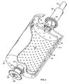
Figure 2 is a fragmentary, perspective view of a roller-heating mechanism; and -
Figure 3 is a perspective view of a pyrolysis machine adapted to the processing of reclaimed tires. - Referring now to the drawing, there is shown in the diagram of
Figure 1 , an apparatus 1 particularly adapted to the practice the ablative pyrolytic process of converting biomass material such as paper, wood chips or other vegetation debris in order to extract from them useful byproducts such as oils or other liquids, and carbon particles and other solids. Thebiomass material 2 is fed to a pair ofcounter-rotating crunching rollers enclosure 5. The biomass material is dropped into the enclosure through a chute 6. The rollers are axially parallel and their circumferential outer surfaces 7, 8 are narrowly spaced-apart to grab, crunch and burn the pieces of biomass material. The walls of the rollers are made of a heat-transmitting material, preferably stainless steel and are heated from the inside. The rollers can include electric heating elements, but are preferably exposed to a flow of highly heated fluid such as a super-heated gas. - As more specifically illustrated in
Figure 2 , a cylindrical body 9 is coaxially housed into eachroller duct 12 passing through anaxial aperture 13 in one of theend walls 14 of the roller. - The chamber has also a plurality of peripheral outlets or
pores 15 which blast a pressurized highly heated fluid admitted through the intake 11 against theinner surface 16 of the roller's circumferential wall. It has been found that this form of impingement heat transfer is highly effective. The highly heated fluid is evacuated from thespace 17 between the cylindrical body 9 and the roller wallinner surface 16 by way of anexit conduit 18 coaxially surrounding theintake duct 12. Theend wall 14 of the roller is rotatively supported by a water-cooledroller bearing 19 fitted around theexit conduit 18. Theopposite end wall 20 of the roller is welded to anaxial shaft 21 supported by an outer structure (not shown in the drawing) by anotherroller bearing 22. The shaft mounts asprocket wheel 23 engaging a chain that drives the roller. Alternately or additionally, anotherexit conduit 24 can be formed through theaxial shaft 21 in communication with a second axial aperture formed through theopposite end wall 20 of the roller. - The highly heated fluid is preferably super-heated steam or highly heated oil or molten salt which is heated to a temperature calculated to incinerate the biomass material over a range of approximately 400 degrees to 1,000 degrees Celsius in a boiler (not shown in the drawing). Turbulences are preferably imparted in the highly heated fluid in order to maximize the heat transfer to the roller. Alternatively, the highly heated fluid can be combustion gasses including an open flame or other plasma generated by electrically ionized gas for example. The combustion gasses can be channeled from an ignition source or can be a fuel ignited in the presence of an oxidizing gas such as air within the rollers. The fuel can by conveniently derived from combustible byproducts of the pyrolytic process itself. Super-heated steam is used as the highly heated fluid in this preferred embodiment.
- As shown in the diagram of
Figure 1 , the outer peripheries of the rollers are surrounded byhemispherical heat shields brackets enclosure 5. Sets of condenser coils 29, 30 into which a cooling fluid is circulated, are positioned between the heat shields and theside walls 31 of the enclosure. The coils cause vaporized fluids such as oil which emanates from the burning biomass material to condense into a liquid which is continuously drained from thebottom pan 32 of the enclosure throughappropriate ports 33 and conduits. - Pulverized or solid residue from the combustion of the biomass material fall into a
trough 34 from which they are extracted by aArchimedes screw 35. - As indicated by the
arrows 36 flow of dry,super-heated steam 37 is injected into thechute 2 throughradial apertures 38 in order to preheat the biomass material. The material is preferably packed and fed loosely to the device in order to allow easy and efficient circulation of the heating steam therethrough. The steam is allowed to escape up the chute. It should be understood that the super-heated, dry steam can be the same fluid that is used for heating the rollers and is fed to the chute from theexit ports 18 of the rollers. - The
enclosure 5 may be subject to a vacuum or to any other type of controlled and regulated atmosphere in order to accommodate a variety of biomass material. The atmosphere may be formulated and adjusted to trigger a specific chemical reaction during the pyrolysis process. - As illustrated in the diagram of
Figure 3 , whole, bulky articles such as the illustratedwom tire 40 may be processed by an adaptation of the above-described apparatus. In this case, the chute is replaced by abox 41 connected through aclosable passageway 42 to aconditioning chamber 43 large enough to accommodate at least one tire. With the passageway hermetically closed by a slidinggate 44 the tire is introduced into the box through afeeding opening 45. Adoor 46 closing the opening is hermetically sealed, and the atmosphere within the box is brought to the same control conditions as the enclosure of the apparatus. When the chamber and the enclosure are in equilibrium, the slidinggate 44 is withdrawn and the tire allowed to roll under gravity and drop toward the rollers. It should be noted that no pre-shredding of the tire is required. - In order to facilitate the ablation of the tire or other biomass material, the outer peripheral surfaces 7,8 of the rollers are provided with
indentations 47 which are interspaced from one roller to the other. More friction and shredding action is obtained by running the rollers at slightly different speeds from one another. At least one of the rollers may be supported by a resilient structure that allows for slight and momentary separation of the rollers when they grab a non-frangible pieces of material. - The rotation of each roller is independent from the other so that not only the speed, but also the direction of rotation may be separately altered to maximize ablation or to clear obstructing matter.
- For best results, wood chips and other vegetable material should have a water content not exceeding approximately 15% per weight. When the heated gas is brought from the rollers into the chute it is still in a super-heated condition but to a lesser degree than when fed to the heating bodies of the rollers. When fed at the base of the chute close to the rollers, the heated gas helps dry and pre-condition the incoming chips, and, at the same time generates a large plume of low temperature steam that drives out any air that is being carried in with the chips. Addition of a small amount of nitrogen gas helps remove any entering oxygen. The dried wood chips now devoid of contaminating oxygen drop out of the chute and accumulate against the rotating rollers at a feeding rate that can be set as a function of the temperature, speed of rotation and the rate of ablation of the wood stock being processed. This feeding method is by design self-regulating, where no special regulating control is needed.
- The ratio of recovered bio-oils and gases, such as methane, carbon monoxide and hydrogen can be modified by adjusting the atmospheric pressure within the chamber, the temperature of the rollers and the degree of preheating. Lower temperatures tend to favor the extraction of organic acids such as formic and acidic acids or alcohols. An halogen atmosphere can yield halogenated bio-oils. Non-condensing gases that accumulate within the enclosure can be collected and exploited as a source or heat or pressure or used in some combustion device to produce energy. The powder or solid residue which is collected at the bottom of the enclosure will include activated carbon. This product is also dependent upon the biomass material condition and the reaction temperature being used and may not need further processing. The carbon residue can also be heated with sulfuric acid to produce carbon disulfide and hydrogen.
- It should also be noted that the use of burning rollers avoids the need of pre-shredding tires and other such items prior to feeding into the pyrolysis apparatus.. Sifting equipment can be used to separate metallic components such as tire belts from carbon residue according to methods well-known to the mechanical arts.
- While the preferred embodiments of the invention have been disclosed, modifications can be made and other embodiments may be devised without departing from the scope of the appended claims.
Claims (13)
- A pyrolytic method for converting biomass material (2), including tires (40), into useful byproducts, which comprises abating, and pyrolizing said biomass material (2,40) between highly heated, counter-rotating crunching rollers (3,4), and turning said rollers (3,4) at slightly different speeds.
- The method of Claim 1, each of said rollers (3,4) having a circumferential surface, the method further comprising heating the circumferential surfaces of said rollers (3,4) with a highly heated fluid.
- The method of Claim 2, wherein said step of heating comprises injecting said highly heated fluid into said rollers (3,4).
- The method of Claim 1, wherein each of said rollers (3, 4) comprises:a circumferential wall;a body (9) coaxially the housed within said roller (3, 4);wherein said body (9) comprises a plurality of peripheral outlets (15) which blast a pressurised highly heated fluid against the inner surface of said circumferential wall.
- The method of Claim 1, which further comprises turning said rollers (3,4) in an opposite rotational direction, whereby an obstruction is cleared.
- The method of Claim 1, which further comprises conducting said ablating in a sealed enclosure (5) under a controlled atmosphere.
- The method of Claim 6, which further comprises conducting said ablating under vacuum.
- The method of Claim 6, which further comprises condensing vaporized fluids present in said enclosure (5).
- The method of Claim 1, which further comprises:feeding said biomass material (2) to said rollers (3,4) through a chute (6); and injecting hot dry steam (37) into said chute (6) to preheat said biomass material (2).
- The method of Claim 3, which further comprises imparting turbulences into said highly heated fluid.
- The method of Claim 1, wherein said rollers (3,4) are heated by heat-transfer from a highly heated fluid.
- The method of Claim 6, wherein said atmosphere is formulated and adjusted to achieve a specific chemical reaction during said processing.
- The method of Claim 11, wherein said highly heated fluid is taken from a group consisting essentially of super-heated steam, highly heated molten salts, highly heated oils, combustion gasses, plasma and open flame.
Applications Claiming Priority (2)
| Application Number | Priority Date | Filing Date | Title |
|---|---|---|---|
| US10/921,033 US7108767B2 (en) | 2004-08-18 | 2004-08-18 | Pyrolysis machine |
| PCT/US2005/029424 WO2006023662A2 (en) | 2004-08-18 | 2005-08-18 | Pyrolysis machine |
Publications (3)
| Publication Number | Publication Date |
|---|---|
| EP1799792A2 EP1799792A2 (en) | 2007-06-27 |
| EP1799792A4 EP1799792A4 (en) | 2010-04-07 |
| EP1799792B1 true EP1799792B1 (en) | 2011-04-06 |
Family
ID=35908632
Family Applications (1)
| Application Number | Title | Priority Date | Filing Date |
|---|---|---|---|
| EP05786681A Expired - Lifetime EP1799792B1 (en) | 2004-08-18 | 2005-08-18 | Pyrolytic method for converting biomass including tires |
Country Status (9)
| Country | Link |
|---|---|
| US (3) | US7108767B2 (en) |
| EP (1) | EP1799792B1 (en) |
| CN (1) | CN101018842A (en) |
| AT (1) | ATE504641T1 (en) |
| AU (1) | AU2005277354A1 (en) |
| CA (1) | CA2619599A1 (en) |
| DE (1) | DE602005027371D1 (en) |
| WO (1) | WO2006023662A2 (en) |
| ZA (1) | ZA200702202B (en) |
Families Citing this family (70)
| Publication number | Priority date | Publication date | Assignee | Title |
|---|---|---|---|---|
| US7108767B2 (en) * | 2004-08-18 | 2006-09-19 | Noto Vincent H | Pyrolysis machine |
| US20090054711A1 (en) * | 2005-05-04 | 2009-02-26 | Tom Lawrence | Pyrolysis Systems, Methods of Use Thereof, and Methods of Bio-Oil Transformation |
| WO2009018595A1 (en) * | 2007-08-09 | 2009-02-12 | Universität Wien | Pyrolysis method and pyrolyzer |
| US8020499B2 (en) * | 2007-11-09 | 2011-09-20 | Overseas Capital Assets Limited | Apparatus and method for pyrolysis of scrap tyres and the like |
| US9688934B2 (en) | 2007-11-23 | 2017-06-27 | Bixby Energy Systems, Inc. | Process for and processor of natural gas and activated carbon together with blower |
| US20090232725A1 (en) * | 2007-11-23 | 2009-09-17 | Sherman Aaron | Flow rate of gas in fluidized bed during conversion of carbon based material to natural gas and activated carbon |
| DE102008049350A1 (en) * | 2008-09-29 | 2010-04-01 | Claas Selbstfahrende Erntemaschinen Gmbh | Thermochemical reactor for a self-propelled harvester |
| WO2010071677A1 (en) * | 2008-12-16 | 2010-06-24 | Kior Inc. | Pretreatment of biomass with carbonaceous material |
| WO2010080733A1 (en) | 2009-01-09 | 2010-07-15 | Cool Planet Biofuels, Llc | System and method for atmospheric carbon sequestration |
| US9909067B2 (en) | 2009-01-21 | 2018-03-06 | Cool Planet Energy Systems, Inc. | Staged biomass fractionator |
| AU2010206956B2 (en) * | 2009-01-21 | 2016-07-14 | Cool Planet Biofuels, Inc. | System and method for biomass fractioning |
| US8217212B2 (en) * | 2009-04-01 | 2012-07-10 | Paoluccio John A | Sequencing retort liquid phase torrefication processing apparatus and method |
| CL2009001034A1 (en) * | 2009-04-30 | 2009-12-04 | Univ Concepcion | Equipment and process for producing bio-fuel by means of rapid pyrolysis of organic material comprising a system of three reactors of fluidized bed in series, lower combustion reactor, intermediate of rapid pyrolysis and superior preheating, in addition to a pneumatic material recirculation system particulate |
| US8657960B2 (en) | 2009-09-29 | 2014-02-25 | Nova Pangaea Technologies, Inc. | Method and system for fractionation of lignocellulosic biomass |
| IN2012DN03077A (en) | 2009-10-14 | 2015-07-31 | Reklaim Inc | |
| US8431757B2 (en) | 2011-03-24 | 2013-04-30 | Cool Planet Biofuels, Inc. | Method for making renewable fuels |
| US8143464B2 (en) | 2011-03-24 | 2012-03-27 | Cool Planet Biofuels, Inc. | Method for making renewable fuels |
| US8951476B2 (en) | 2011-03-24 | 2015-02-10 | Cool Planet Energy Systems, Inc. | System for making renewable fuels |
| US8137628B2 (en) * | 2011-03-24 | 2012-03-20 | Cool Planet Biofuels, Inc. | System for making renewable fuels |
| US8367881B2 (en) | 2011-05-09 | 2013-02-05 | Cool Planet Biofuels, Inc. | Method for biomass fractioning by enhancing biomass thermal conductivity |
| US8173044B1 (en) | 2011-05-09 | 2012-05-08 | Cool Planet Biofuels, Inc. | Process for biomass conversion to synthesis gas |
| US10322389B2 (en) | 2014-10-01 | 2019-06-18 | Cool Planet Energy Systems, Inc. | Biochar aggregate particles |
| US10173937B2 (en) | 2011-06-06 | 2019-01-08 | Cool Planet Energy Systems, Inc. | Biochar as a microbial carrier |
| US9493380B2 (en) | 2011-06-06 | 2016-11-15 | Cool Planet Energy Systems, Inc. | Method for enhancing soil growth using bio-char |
| US11214528B2 (en) | 2011-06-06 | 2022-01-04 | Carbon Technology Holdings, LLC | Treated biochar for use in water treatment systems |
| US10392313B2 (en) | 2011-06-06 | 2019-08-27 | Cool Planet Energy Systems, Inc. | Method for application of biochar in turf grass and landscaping environments |
| US9216916B2 (en) | 2013-10-25 | 2015-12-22 | Cool Planet Energy Systems, Inc. | System and method for purifying process water produced from biomass conversion to fuels |
| US9493379B2 (en) | 2011-07-25 | 2016-11-15 | Cool Planet Energy Systems, Inc. | Method for the bioactivation of biochar for use as a soil amendment |
| US10118870B2 (en) | 2011-06-06 | 2018-11-06 | Cool Planet Energy Systems, Inc. | Additive infused biochar |
| US11279662B2 (en) | 2011-06-06 | 2022-03-22 | Carbon Technology Holdings, LLC | Method for application of biochar in turf grass and landscaping environments |
| US8317891B1 (en) | 2011-06-06 | 2012-11-27 | Cool Planet Biofuels, Inc. | Method for enhancing soil growth using bio-char |
| US8568493B2 (en) | 2011-07-25 | 2013-10-29 | Cool Planet Energy Systems, Inc. | Method for producing negative carbon fuel |
| US10059634B2 (en) | 2011-06-06 | 2018-08-28 | Cool Planet Energy Systems, Inc. | Biochar suspended solution |
| US12084392B2 (en) | 2011-06-06 | 2024-09-10 | Carbon Technology Holdings, LLC | Treated biochar for use in water treatment systems |
| US9980912B2 (en) | 2014-10-01 | 2018-05-29 | Cool Planet Energy Systems, Inc. | Biochars for use with animals |
| US9809502B2 (en) | 2011-06-06 | 2017-11-07 | Cool Planet Energy Systems, Inc. | Enhanced Biochar |
| US10696603B2 (en) | 2011-06-06 | 2020-06-30 | Carbon Technology Holdings, LLC | Mineral solubilizing microorganism infused biochars |
| US10550044B2 (en) | 2011-06-06 | 2020-02-04 | Cool Planet Energy Systems, Inc. | Biochar coated seeds |
| US10252951B2 (en) | 2011-06-06 | 2019-04-09 | Cool Planet Energy Systems, Inc. | Biochars and biochar treatment processes |
| US10233129B2 (en) | 2011-06-06 | 2019-03-19 | Cool Planet Energy Systems, Inc. | Methods for application of biochar |
| US12421176B2 (en) | 2011-06-06 | 2025-09-23 | Carbon Technology Holdings, LLC | Biochar as a microbial carrier |
| US12054440B2 (en) | 2011-06-06 | 2024-08-06 | Carbon Technology Holdings, LLC | Method for application of biochar in turf grass and landscaping environments |
| US10640429B2 (en) | 2011-06-06 | 2020-05-05 | Cool Planet Energy System, Inc. | Methods for application of biochar |
| US9260666B2 (en) | 2011-07-25 | 2016-02-16 | Cool Planet Energy Systems, Inc. | Method for reducing the carbon footprint of a conversion process |
| US9605211B2 (en) | 2012-09-11 | 2017-03-28 | D4 Energy Group, Inc. | Process and device for devolatizing feedstock |
| US9745516B2 (en) * | 2013-03-15 | 2017-08-29 | All Power Labs, Inc. | Simultaneous pyrolysis and communition for fuel flexible gasification and pyrolysis |
| CN103788971B (en) * | 2014-01-16 | 2015-12-23 | 华北电力大学 | A kind of apparatus and method of roller press type biomass pyrolytic Poly-generation |
| US11097241B2 (en) | 2014-10-01 | 2021-08-24 | Talipot Cool Extract (Ip), Llc | Biochars, biochar extracts and biochar extracts having soluble signaling compounds and method for capturing material extracted from biochar |
| EP3200915A4 (en) | 2014-10-01 | 2018-06-20 | Cool Planet Energy Systems, Inc. | Biochars and biochar treatment processes |
| US11053171B2 (en) | 2014-10-01 | 2021-07-06 | Carbon Technology Holdings, LLC | Biochars for use with animals |
| US11426350B1 (en) | 2014-10-01 | 2022-08-30 | Carbon Technology Holdings, LLC | Reducing the environmental impact of farming using biochar |
| US12599151B2 (en) | 2014-10-01 | 2026-04-14 | Talipot Cool Extract (Ip), Llc | Biochars, biochar extracts and biochar extracts having soluble signaling compounds and method for capturing material extracted from biochar |
| US10870608B1 (en) | 2014-10-01 | 2020-12-22 | Carbon Technology Holdings, LLC | Biochar encased in a biodegradable material |
| US10472297B2 (en) | 2014-10-01 | 2019-11-12 | Cool Planet Energy System, Inc. | Biochars for use in composting |
| SE539173C2 (en) * | 2014-12-22 | 2017-05-02 | Valmet Oy | A system for feeding lignocellulosic biomass material to a hydrolysis or pre-hydrolysis process |
| DK201670548A1 (en) * | 2016-07-21 | 2018-02-19 | Syntes One Eng Group Aps | Pyrolysis system and process |
| MX2020006266A (en) | 2017-12-15 | 2021-01-20 | Talipot Cool Extract Ip Llc | Biochars and biochar extracts having soluble signaling compounds and method for capturing material extracted from biochar. |
| US10604704B2 (en) * | 2018-05-07 | 2020-03-31 | Vorsana Inc | Shear retort for ablative pyrolysis |
| CA3103065A1 (en) * | 2018-06-19 | 2019-12-26 | Waste to Energy Technology Ltd | Method and system for processing a material |
| GB2574833B (en) * | 2018-06-19 | 2021-02-17 | Waste To Energy Tech Ltd | Pyrolysis system and method |
| GB2587566B (en) * | 2018-06-19 | 2021-10-20 | Waste To Energy Tech Ltd | Pyrolysis system and method |
| CN110527532A (en) * | 2019-07-29 | 2019-12-03 | 中国电建集团西北勘测设计研究院有限公司 | A kind of engagement roll-type refuse pyrolysis system and method |
| KR102202452B1 (en) * | 2019-09-09 | 2021-01-13 | 조오현 | Method for manufacturing micro wood chip for use as fuel of thermal power plant using unused forest resources |
| CN116134118A (en) | 2020-09-14 | 2023-05-16 | 埃科莱布美国股份有限公司 | Cold-flow additives for plastic-derived synthetic feedstocks |
| CN112495995B (en) * | 2020-11-14 | 2022-08-02 | 永康市凡谷进出口有限公司 | Kitchen garbage disposal machine |
| CN112676003A (en) * | 2020-12-28 | 2021-04-20 | 泉州市洛江奎芳保洁有限公司 | Kitchen garbage disposal box |
| JP2024509805A (en) | 2021-03-10 | 2024-03-05 | エコラボ ユーエスエー インコーポレイティド | Stabilizing additive for synthetic raw materials derived from plastics |
| EP4416248A1 (en) | 2021-10-14 | 2024-08-21 | Ecolab Usa Inc. | Antifouling agents for plastic-derived synthetic feedstocks |
| CN114231305B (en) * | 2021-12-30 | 2023-09-01 | 营口聚鑫生物新能源有限公司 | Circulation heating biomass fuel is with preventing blockking up carbonization device |
| EP4253504A1 (en) * | 2022-04-01 | 2023-10-04 | Lauridsen Holding, Skjern ApS | Friction heated pyrolysis unit and method for friction heating a biomass pyrolysis unit |
Family Cites Families (13)
| Publication number | Priority date | Publication date | Assignee | Title |
|---|---|---|---|---|
| US2279577A (en) * | 1941-05-02 | 1942-04-14 | Horace G Martin | Incinerator in combination with latrines or the like |
| GB1588926A (en) * | 1976-09-27 | 1981-04-29 | Ricoh Kk | Heat fixing apparatus |
| US4269593A (en) * | 1979-12-21 | 1981-05-26 | Allis-Chalmers Corporation | Roller grate material bed conveying and heat exchange apparatus providing plural bed depths |
| US4461674A (en) * | 1981-12-31 | 1984-07-24 | Allis-Chalmers Corporation | Apparatus for recovery of different weight fractions of oil from shale |
| US5294766A (en) * | 1989-11-15 | 1994-03-15 | Brotz Gregory R | Structure for high-temperature mill rolling of compounds |
| WO1991014554A1 (en) * | 1990-03-22 | 1991-10-03 | Odessky Gosudarstvenny Universitet | Method for extraction of metal reinforcement from rubber tyres |
| DE69108409T2 (en) * | 1990-12-03 | 1995-11-09 | Ireton Int Inc | METHOD FOR ABLATION HEAT TRANSFER. |
| CA2128523C (en) * | 1992-04-29 | 2005-12-20 | Franz Haimer | Device for pelletizing vegetable material |
| US6436356B1 (en) * | 2000-03-28 | 2002-08-20 | Comsyntech Ltd. | Apparatus for self-propagating high temperature synthesis |
| CA2348221A1 (en) * | 2001-05-23 | 2002-11-23 | Florencio Neto Palma | Hydrogen oil sand extraction apparatus |
| GB0200476D0 (en) * | 2002-01-10 | 2002-02-27 | Univ Aston | Reactor |
| ATE506425T1 (en) * | 2003-02-25 | 2011-05-15 | Pytec Thermochemische Anlagen Gmbh | METHOD AND DEVICE FOR PYROLYSIS OF BIOMASS |
| US7108767B2 (en) * | 2004-08-18 | 2006-09-19 | Noto Vincent H | Pyrolysis machine |
-
2004
- 2004-08-18 US US10/921,033 patent/US7108767B2/en not_active Expired - Fee Related
-
2005
- 2005-08-18 WO PCT/US2005/029424 patent/WO2006023662A2/en not_active Ceased
- 2005-08-18 US US11/660,571 patent/US7857943B2/en not_active Expired - Fee Related
- 2005-08-18 AT AT05786681T patent/ATE504641T1/en not_active IP Right Cessation
- 2005-08-18 CN CNA2005800286188A patent/CN101018842A/en active Pending
- 2005-08-18 CA CA002619599A patent/CA2619599A1/en not_active Abandoned
- 2005-08-18 DE DE602005027371T patent/DE602005027371D1/en not_active Expired - Lifetime
- 2005-08-18 AU AU2005277354A patent/AU2005277354A1/en not_active Abandoned
- 2005-08-18 EP EP05786681A patent/EP1799792B1/en not_active Expired - Lifetime
-
2007
- 2007-03-16 ZA ZA200702202A patent/ZA200702202B/en unknown
-
2010
- 2010-12-27 US US12/978,707 patent/US8604259B2/en not_active Expired - Fee Related
Also Published As
| Publication number | Publication date |
|---|---|
| US20060037852A1 (en) | 2006-02-23 |
| US8604259B2 (en) | 2013-12-10 |
| ZA200702202B (en) | 2008-12-31 |
| US20080093209A1 (en) | 2008-04-24 |
| US7108767B2 (en) | 2006-09-19 |
| US20110089014A1 (en) | 2011-04-21 |
| ATE504641T1 (en) | 2011-04-15 |
| AU2005277354A1 (en) | 2006-03-02 |
| EP1799792A4 (en) | 2010-04-07 |
| US7857943B2 (en) | 2010-12-28 |
| EP1799792A2 (en) | 2007-06-27 |
| WO2006023662A2 (en) | 2006-03-02 |
| CN101018842A (en) | 2007-08-15 |
| CA2619599A1 (en) | 2006-03-02 |
| WO2006023662A3 (en) | 2006-11-09 |
| DE602005027371D1 (en) | 2011-05-19 |
Similar Documents
| Publication | Publication Date | Title |
|---|---|---|
| US7857943B2 (en) | Pyrolysis machine | |
| AU2010268415B2 (en) | Waste management system | |
| JP3602504B2 (en) | Heat treatment equipment using superheated steam | |
| US5205225A (en) | Apparatus for allowing thermal dimensional changes of metal parts in a retort mechanism | |
| PT106729A (en) | HIGH ENERGY EFFICIENCY BIOMASS CONVERSION PROCESS | |
| US5224432A (en) | Method for retorting organic matter | |
| JP2001031412A (en) | Multi-state type rotary kiln | |
| CN109052889A (en) | Indirect heating packaged type industrial sludge continuous pyrolysis method and carbonizing plant | |
| KR100557676B1 (en) | Organic waste carbonization method and apparatus | |
| US7147681B1 (en) | Method and device for removing recoverable waste products and non-recoverable waste products | |
| JPH11286684A (en) | Continuous carbonization furnace | |
| JP5176016B2 (en) | Superheated steam continuous recycling equipment | |
| US5220873A (en) | Apparatus for retorting organic matter | |
| US20110290632A1 (en) | Novel Off-Gas System for Coal and Biomass Pyrolysis | |
| KR101337493B1 (en) | Pyrolysis apparatus for organic waste | |
| CN213160834U (en) | An electromagnetic induction thermal desorption treatment system | |
| JP2004189848A (en) | Carbonization method and carbonization system | |
| CN112393247A (en) | Low-temperature thin-layer quick-heating gradient anaerobic pyrolysis system and solid waste pyrolysis system based on same | |
| RU2481528C2 (en) | High-temperature plant for heat treatment of solid medical waste | |
| RU2816423C1 (en) | Installation for processing solid organic waste | |
| WO2011004064A1 (en) | An apparatus for thermally treating organic material and method for using the apparatus | |
| KR20230161576A (en) | Continuous waste treatment system and process | |
| KR20090011941U (en) | Transfer screw of waste pyrolysis device | |
| JP2001116237A (en) | Device and method for treating plant-family waste | |
| JP2005272551A (en) | Method and plant for pyrolysis processing |
Legal Events
| Date | Code | Title | Description |
|---|---|---|---|
| PUAI | Public reference made under article 153(3) epc to a published international application that has entered the european phase |
Free format text: ORIGINAL CODE: 0009012 |
|
| 17P | Request for examination filed |
Effective date: 20070316 |
|
| AK | Designated contracting states |
Kind code of ref document: A2 Designated state(s): AT BE BG CH CY CZ DE DK EE ES FI FR GB GR HU IE IS IT LI LT LU LV MC NL PL PT RO SE SI SK TR |
|
| DAX | Request for extension of the european patent (deleted) | ||
| A4 | Supplementary search report drawn up and despatched |
Effective date: 20100309 |
|
| RIC1 | Information provided on ipc code assigned before grant |
Ipc: C10B 53/02 20060101AFI20100303BHEP Ipc: C10B 47/32 20060101ALI20100303BHEP Ipc: C10B 53/07 20060101ALI20100303BHEP |
|
| 17Q | First examination report despatched |
Effective date: 20100701 |
|
| GRAP | Despatch of communication of intention to grant a patent |
Free format text: ORIGINAL CODE: EPIDOSNIGR1 |
|
| GRAC | Information related to communication of intention to grant a patent modified |
Free format text: ORIGINAL CODE: EPIDOSCIGR1 |
|
| RIC1 | Information provided on ipc code assigned before grant |
Ipc: C10B 53/07 20060101ALI20101011BHEP Ipc: C10B 53/02 20060101AFI20101011BHEP Ipc: C10B 47/32 20060101ALI20101011BHEP Ipc: C10G 1/10 20060101ALI20101011BHEP |
|
| RTI1 | Title (correction) |
Free format text: PYROLYTIC METHOD FOR CONVERTING BIOMASS INCLUDING TIRES |
|
| GRAS | Grant fee paid |
Free format text: ORIGINAL CODE: EPIDOSNIGR3 |
|
| GRAA | (expected) grant |
Free format text: ORIGINAL CODE: 0009210 |
|
| AK | Designated contracting states |
Kind code of ref document: B1 Designated state(s): AT BE BG CH CY CZ DE DK EE ES FI FR GB GR HU IE IS IT LI LT LU LV MC NL PL PT RO SE SI SK TR |
|
| REG | Reference to a national code |
Ref country code: GB Ref legal event code: FG4D |
|
| REG | Reference to a national code |
Ref country code: CH Ref legal event code: EP |
|
| REG | Reference to a national code |
Ref country code: IE Ref legal event code: FG4D |
|
| REF | Corresponds to: |
Ref document number: 602005027371 Country of ref document: DE Date of ref document: 20110519 Kind code of ref document: P |
|
| REG | Reference to a national code |
Ref country code: DE Ref legal event code: R096 Ref document number: 602005027371 Country of ref document: DE Effective date: 20110519 |
|
| REG | Reference to a national code |
Ref country code: NL Ref legal event code: VDEP Effective date: 20110406 |
|
| PG25 | Lapsed in a contracting state [announced via postgrant information from national office to epo] |
Ref country code: SI Free format text: LAPSE BECAUSE OF FAILURE TO SUBMIT A TRANSLATION OF THE DESCRIPTION OR TO PAY THE FEE WITHIN THE PRESCRIBED TIME-LIMIT Effective date: 20110406 |
|
| LTIE | Lt: invalidation of european patent or patent extension |
Effective date: 20110406 |
|
| PG25 | Lapsed in a contracting state [announced via postgrant information from national office to epo] |
Ref country code: SE Free format text: LAPSE BECAUSE OF FAILURE TO SUBMIT A TRANSLATION OF THE DESCRIPTION OR TO PAY THE FEE WITHIN THE PRESCRIBED TIME-LIMIT Effective date: 20110406 Ref country code: LT Free format text: LAPSE BECAUSE OF FAILURE TO SUBMIT A TRANSLATION OF THE DESCRIPTION OR TO PAY THE FEE WITHIN THE PRESCRIBED TIME-LIMIT Effective date: 20110406 Ref country code: PT Free format text: LAPSE BECAUSE OF FAILURE TO SUBMIT A TRANSLATION OF THE DESCRIPTION OR TO PAY THE FEE WITHIN THE PRESCRIBED TIME-LIMIT Effective date: 20110808 |
|
| PG25 | Lapsed in a contracting state [announced via postgrant information from national office to epo] |
Ref country code: CY Free format text: LAPSE BECAUSE OF FAILURE TO SUBMIT A TRANSLATION OF THE DESCRIPTION OR TO PAY THE FEE WITHIN THE PRESCRIBED TIME-LIMIT Effective date: 20110406 Ref country code: ES Free format text: LAPSE BECAUSE OF FAILURE TO SUBMIT A TRANSLATION OF THE DESCRIPTION OR TO PAY THE FEE WITHIN THE PRESCRIBED TIME-LIMIT Effective date: 20110717 Ref country code: AT Free format text: LAPSE BECAUSE OF FAILURE TO SUBMIT A TRANSLATION OF THE DESCRIPTION OR TO PAY THE FEE WITHIN THE PRESCRIBED TIME-LIMIT Effective date: 20110406 Ref country code: IS Free format text: LAPSE BECAUSE OF FAILURE TO SUBMIT A TRANSLATION OF THE DESCRIPTION OR TO PAY THE FEE WITHIN THE PRESCRIBED TIME-LIMIT Effective date: 20110806 Ref country code: FI Free format text: LAPSE BECAUSE OF FAILURE TO SUBMIT A TRANSLATION OF THE DESCRIPTION OR TO PAY THE FEE WITHIN THE PRESCRIBED TIME-LIMIT Effective date: 20110406 Ref country code: LV Free format text: LAPSE BECAUSE OF FAILURE TO SUBMIT A TRANSLATION OF THE DESCRIPTION OR TO PAY THE FEE WITHIN THE PRESCRIBED TIME-LIMIT Effective date: 20110406 Ref country code: BE Free format text: LAPSE BECAUSE OF FAILURE TO SUBMIT A TRANSLATION OF THE DESCRIPTION OR TO PAY THE FEE WITHIN THE PRESCRIBED TIME-LIMIT Effective date: 20110406 Ref country code: GR Free format text: LAPSE BECAUSE OF FAILURE TO SUBMIT A TRANSLATION OF THE DESCRIPTION OR TO PAY THE FEE WITHIN THE PRESCRIBED TIME-LIMIT Effective date: 20110707 |
|
| PG25 | Lapsed in a contracting state [announced via postgrant information from national office to epo] |
Ref country code: NL Free format text: LAPSE BECAUSE OF FAILURE TO SUBMIT A TRANSLATION OF THE DESCRIPTION OR TO PAY THE FEE WITHIN THE PRESCRIBED TIME-LIMIT Effective date: 20110406 |
|
| PG25 | Lapsed in a contracting state [announced via postgrant information from national office to epo] |
Ref country code: EE Free format text: LAPSE BECAUSE OF FAILURE TO SUBMIT A TRANSLATION OF THE DESCRIPTION OR TO PAY THE FEE WITHIN THE PRESCRIBED TIME-LIMIT Effective date: 20110406 Ref country code: CZ Free format text: LAPSE BECAUSE OF FAILURE TO SUBMIT A TRANSLATION OF THE DESCRIPTION OR TO PAY THE FEE WITHIN THE PRESCRIBED TIME-LIMIT Effective date: 20110406 |
|
| PLBE | No opposition filed within time limit |
Free format text: ORIGINAL CODE: 0009261 |
|
| STAA | Information on the status of an ep patent application or granted ep patent |
Free format text: STATUS: NO OPPOSITION FILED WITHIN TIME LIMIT |
|
| PG25 | Lapsed in a contracting state [announced via postgrant information from national office to epo] |
Ref country code: PL Free format text: LAPSE BECAUSE OF FAILURE TO SUBMIT A TRANSLATION OF THE DESCRIPTION OR TO PAY THE FEE WITHIN THE PRESCRIBED TIME-LIMIT Effective date: 20110406 Ref country code: SK Free format text: LAPSE BECAUSE OF FAILURE TO SUBMIT A TRANSLATION OF THE DESCRIPTION OR TO PAY THE FEE WITHIN THE PRESCRIBED TIME-LIMIT Effective date: 20110406 Ref country code: DK Free format text: LAPSE BECAUSE OF FAILURE TO SUBMIT A TRANSLATION OF THE DESCRIPTION OR TO PAY THE FEE WITHIN THE PRESCRIBED TIME-LIMIT Effective date: 20110406 Ref country code: RO Free format text: LAPSE BECAUSE OF FAILURE TO SUBMIT A TRANSLATION OF THE DESCRIPTION OR TO PAY THE FEE WITHIN THE PRESCRIBED TIME-LIMIT Effective date: 20110406 |
|
| 26N | No opposition filed |
Effective date: 20120110 |
|
| PG25 | Lapsed in a contracting state [announced via postgrant information from national office to epo] |
Ref country code: MC Free format text: LAPSE BECAUSE OF NON-PAYMENT OF DUE FEES Effective date: 20110831 |
|
| REG | Reference to a national code |
Ref country code: CH Ref legal event code: PL |
|
| GBPC | Gb: european patent ceased through non-payment of renewal fee |
Effective date: 20110818 |
|
| PG25 | Lapsed in a contracting state [announced via postgrant information from national office to epo] |
Ref country code: CH Free format text: LAPSE BECAUSE OF NON-PAYMENT OF DUE FEES Effective date: 20110831 Ref country code: LI Free format text: LAPSE BECAUSE OF NON-PAYMENT OF DUE FEES Effective date: 20110831 |
|
| REG | Reference to a national code |
Ref country code: DE Ref legal event code: R097 Ref document number: 602005027371 Country of ref document: DE Effective date: 20120110 |
|
| REG | Reference to a national code |
Ref country code: FR Ref legal event code: ST Effective date: 20120430 |
|
| REG | Reference to a national code |
Ref country code: IE Ref legal event code: MM4A |
|
| REG | Reference to a national code |
Ref country code: DE Ref legal event code: R119 Ref document number: 602005027371 Country of ref document: DE Effective date: 20120301 |
|
| PG25 | Lapsed in a contracting state [announced via postgrant information from national office to epo] |
Ref country code: IE Free format text: LAPSE BECAUSE OF NON-PAYMENT OF DUE FEES Effective date: 20110818 |
|
| PG25 | Lapsed in a contracting state [announced via postgrant information from national office to epo] |
Ref country code: FR Free format text: LAPSE BECAUSE OF NON-PAYMENT OF DUE FEES Effective date: 20110831 Ref country code: GB Free format text: LAPSE BECAUSE OF NON-PAYMENT OF DUE FEES Effective date: 20110818 |
|
| PG25 | Lapsed in a contracting state [announced via postgrant information from national office to epo] |
Ref country code: LU Free format text: LAPSE BECAUSE OF NON-PAYMENT OF DUE FEES Effective date: 20110818 |
|
| PG25 | Lapsed in a contracting state [announced via postgrant information from national office to epo] |
Ref country code: BG Free format text: LAPSE BECAUSE OF FAILURE TO SUBMIT A TRANSLATION OF THE DESCRIPTION OR TO PAY THE FEE WITHIN THE PRESCRIBED TIME-LIMIT Effective date: 20110706 Ref country code: DE Free format text: LAPSE BECAUSE OF NON-PAYMENT OF DUE FEES Effective date: 20120301 |
|
| PG25 | Lapsed in a contracting state [announced via postgrant information from national office to epo] |
Ref country code: TR Free format text: LAPSE BECAUSE OF FAILURE TO SUBMIT A TRANSLATION OF THE DESCRIPTION OR TO PAY THE FEE WITHIN THE PRESCRIBED TIME-LIMIT Effective date: 20110406 |
|
| PG25 | Lapsed in a contracting state [announced via postgrant information from national office to epo] |
Ref country code: HU Free format text: LAPSE BECAUSE OF FAILURE TO SUBMIT A TRANSLATION OF THE DESCRIPTION OR TO PAY THE FEE WITHIN THE PRESCRIBED TIME-LIMIT Effective date: 20110406 |
|
| PG25 | Lapsed in a contracting state [announced via postgrant information from national office to epo] |
Ref country code: IT Free format text: LAPSE BECAUSE OF FAILURE TO SUBMIT A TRANSLATION OF THE DESCRIPTION OR TO PAY THE FEE WITHIN THE PRESCRIBED TIME-LIMIT Effective date: 20110406 |