EP1799092B1 - Mop bucket system with wave reduction capability - Google Patents
Mop bucket system with wave reduction capability Download PDFInfo
- Publication number
- EP1799092B1 EP1799092B1 EP05796652A EP05796652A EP1799092B1 EP 1799092 B1 EP1799092 B1 EP 1799092B1 EP 05796652 A EP05796652 A EP 05796652A EP 05796652 A EP05796652 A EP 05796652A EP 1799092 B1 EP1799092 B1 EP 1799092B1
- Authority
- EP
- European Patent Office
- Prior art keywords
- mop bucket
- height
- sidewall
- bucket system
- liquid
- Prior art date
- Legal status (The legal status is an assumption and is not a legal conclusion. Google has not performed a legal analysis and makes no representation as to the accuracy of the status listed.)
- Expired - Lifetime
Links
Images





Classifications
-
- A—HUMAN NECESSITIES
- A47—FURNITURE; DOMESTIC ARTICLES OR APPLIANCES; COFFEE MILLS; SPICE MILLS; SUCTION CLEANERS IN GENERAL
- A47J—KITCHEN EQUIPMENT; COFFEE MILLS; SPICE MILLS; APPARATUS FOR MAKING BEVERAGES
- A47J47/00—Kitchen containers, stands or the like, not provided for in other groups of this subclass; Cutting-boards, e.g. for bread
- A47J47/18—Pails for kitchen use
-
- A—HUMAN NECESSITIES
- A47—FURNITURE; DOMESTIC ARTICLES OR APPLIANCES; COFFEE MILLS; SPICE MILLS; SUCTION CLEANERS IN GENERAL
- A47L—DOMESTIC WASHING OR CLEANING; SUCTION CLEANERS IN GENERAL
- A47L13/00—Implements for cleaning floors, carpets, furniture, walls, or wall coverings
- A47L13/10—Scrubbing; Scouring; Cleaning; Polishing
- A47L13/50—Auxiliary implements
- A47L13/58—Wringers for scouring pads, mops, or the like, combined with buckets
Definitions
- Mop bucket systems are commonly used for cleaning purposes.
- a mop bucket contains liquid used for cleaning. It is typically used to facilitate the mopping of floors.
- cleaning liquid may spill or splash during use.
- the mop bucket and cleaning liquid must be moved from one location to another.
- the mop bucket will be subjected to differing Newtonian forces.
- the mop bucket will experience a starting force as it is initially accelerated toward the next location and will experience a stopping force when it reaches that location and is decelerated.
- it may experience instantaneous turbulent forces at the interface between the liquid and air, sometimes called wave amplification or ripples.
- the changing forces on the mop bucket will cause the cleaning liquid to be displaced relative to the mop bucket.
- the displacement of the cleaning liquid can result in the formation of a wave that splashes over the top of a wall of the mop bucket and out onto a floor or stairway. Also, the amplification of these waves due to the high degree of turbulence may also cause splashing and liquid droplets to exit the mop bucket.
- Spillage of the cleaning liquid is problematic. For example cleaning liquid that has spilled out of the mop bucket onto a floor or stairway create a slip-and-fall hazard if not immediately removed. Even if the liquid is immediately removed, nonproductive man hours are required to clean the spill. Spillage also is inefficient and undesirable because it can result in the loss of cleaning liquid.
- U.S. patent 3,341,876 discloses a bucket with an integral baffle means which inhibits sloshing of liquid as the bucket s moved along the floor, and which serves as a structural stiffening or buttressing member.
- the baffle separates the bucket into two compartments and includes baffle member that is integrally formed during molding.
- the central portion of the baffle member is almost the height of the side walls and has a flat, downwardly sloping top surface.
- WO 95/27433 discloses a water container to be used with as rubber scraper.
- EP 0781 524 discloses a container with a wetting chamber for immersion of a cleaning tool, such s a mop; a storage chamber for storing cleaning fluid; and as proportioning valve controlling the supply of cleaning fluid from the storage chamber to the wetting chamber.
- a partition divides the storage chamber from the wetting chamber in which the two chambers are connected by a connecting channel through which cleaning fluid may pass upon the opening of the proportioning valve.
- the wetting chamber is provided with at least one raised portion which is constructed as a transverse rib for supporting a stripping element. The stripping element limits the depth of the immersion tool in the wetting chamber and the degree of opening of the proportioning valve.
- the present invention relates to a mop bucket system including a liquid-retaining portion and an energy-dissipation device.
- the liquid-retaining portion is configured to retain liquid. It has a bottom wall portion, a first sidewall portion, a second sidewall portion facing the first sidewall portion, a third sidewall portion, and a fourth sidewall portion facing the third sidewall portion.
- the liquid- retaining portion permits retained liquid to move in a liquid-movement direction extending from the first sidewall portion toward the second sidewall portion within a higher-momentum region having a width that is approximately 70% of a distance between the third sidewall portion and the fourth sidewall portion.
- the energy-dissipation device is disposed within the liquid-retaining portion and extends into the higher-momentum region.
- the energy-dissipation device is configured to inhibit build up of momentum of liquid in the higher-momentum region along at least a portion of the liquid-movement direction by breaking surface tension of the liquid.
- the mop bucket system is characterised in that energy dissipation device includes a first baffle and a second baffle each disposed between the first and second sidewall portions and within the higher momentum region, the first baffle projecting from the third sidewall portion and the second baffle projecting from the fourth sidewall portion.
- Figure 1 is a front perspective view of a first embodiment of a mop bucket system according to the present invention
- Figure 2 is a front perspective view of the mop bucket system of Figure 1;
- Figure 3 is a side, cross-sectional view of the mop bucket system of Figure 1 ;
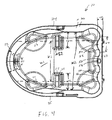
- Figure 4 is a plan view of the mop bucket system of Figure 1 ;
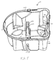
- Figure 5 is side, perspective view of the mop bucket system of Figure 1 ;
- Figure 6 is a rear, perspective view of a mop bucket system which is however not according to the present invention.
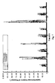
- Figure 7 is graph showing data from a simulation comparing the performance of mop bucket systems at one-quarter of full capacity
- Figure 8 is graph showing data from a simulation comparing the performance of mop bucket systems at one-quarter of full capacity
- Figure 9 is graph showing data from a simulation comparing the performance of mop bucket systems at one-half of full capacity.
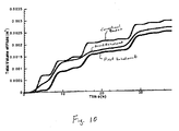
- Figure 10 is graph showing data from a simulation comparing the performance of mop bucket systems at one-half of full capacity.
- a mop bucket system 10 according to the present invention is shown in Figures 1-5 .
- the mop bucket system 10 includes a liquid-retaining portion 20 and an energy-dissipation device 50.
- the mop bucket system 10 also can include a wringer 33 and a bucket 34 for receiving dirty water from the wringer 33.
- a mop bucket 11 can provide the liquid-retaining portion 20, which is configured to retain liquid, such as cleaning liquid used to mop floors.
- the liquid-retaining portion 20 could be provided by other container structures, such as drinking cups or mugs, if intended for use in systems other than a mop bucket system.
- the liquid-retaining portion 20 includes a bottom wall portion 21, a first sidewall portion 22, a second sidewall portion 23 facing the first sidewall portion 22, a third sidewall portion 24, and a fourth sidewall portion 25 facing the third sidewall portion 24.
- the sidewall portions 22, 23, 24, 25 can be connected in a variety of forms.
- they can be portions of a rounded sidewall with no clear demarcations between the sidewall portions (see, for example, the connection between sidewall portions 22 and 24) or they can be connected by distinct corners or edges that provide clear demarcations between the sidewall portions (see, for example, the connection between sidewall portions 23 and 24).
- the sidewall portions 22, 23, 24, 25 can have approximately the same height. It is more preferred, however, that the first sidewall portion 22 be shorter than the second sidewall portion 23. As shown in Figure 3 , in this referred embodiment, the first sidewall portion 22 has a height H1 of approximately 30,5 cm (12 inches) (more preferably 11.98 inches) and the second sidewall portion 23 has a height H2 of approximately 38,1 cm (15 inches), (more preferably 14.73 inches). The height of the third and fourth sidewall portions 24, 25 tapers between the heights of the first and second sidewall portions 22, 23.
- liquid When the mop bucket system 10 is subjected to differing forces, liquid will be displaced relative to the liquid-retaining portion 20. For example, if the mop bucket system 10 is moved in the direction of the arrow A shown in Figure 3 , the liquid (not shown) will move in an opposite direction relative to the liquid-retaining portion 20, i.e., in a liquid-movement direction extending from the first sidewall portion 22 toward the second sidewall portion 23.
- the displacement of the liquid will not be evenly distributed.
- the energy of the liquid at the center is greater than along the third and fourth sidewall portions 24, 25, because of the no-slip boundary condition, i.e., forces along the third and fourth sidewall portions 24, 25 will slow the movement of the liquid near those sidewall portions. Consequently, a higher-momentum region will exist in the liquid.
- boundaries of the higher-momentum region have been established by showing dashed lines 27 in Figure 4 , which have a width W1 between them.
- the width W1 preferably is approximately 70% of a distance W2 between the third and fourth sidewall portions 24, 25, though W1 could be redefined as, for example, approximately 65%, 50%, or 30% of the distance W2, depending on the preferred implementation and goals to be achieved.
- the higher-momentum region has a center that coincides with the center of the liquid-retaining portion 20.
- the mop bucket system 10 may have rolling members 30, such as casters, to facilitate movement of the mop bucket system 10.
- the rolling members 30 preferably are connected to a dolly 31, which receives the liquid-retaining portion 20, as shown in the exploded view of Figure 2 .
- the rolling members can be directly connected to the bottom of the liquid-retaining portion 20.
- the rolling members can be omitted and the mop bucket system 10 could be moved from location to location by carrying the mop bucket system 10.
- the energy-dissipation device 50 is disposed within the liquid-retaining portion 20 and extends into the higher-momentum region between the dashed lines 27.
- the energy-dissipation device 50 can be configured to inhibit build up of momentum of liquid in the higher-momentum region and inhibit wave-amplification at the liquid surface region along at least a portion of the liquid-movement direction by breaking surface tension of the liquid. Under ideal operating conditions, the energy-dissipation device extends above the liquid surface.
- the energy-dissipation device 50 includes first baffle 52 and a second baffle 54 disposed between the first and second sidewall portions 22, 23 and within the higher-momentum region.
- the first and second baffles 52, 54 can be generally planar members that inhibit the flow of liquid.
- the first baffle 52 projects from the third sidewall portion 24 and the second baffle 54 projects from the fourth sidewall portion 25.
- the first and second baffles 52, 54 each project a distance W3 (see Figure 4 ) of approximately) 6,5 cm (2.5 inches) (more preferably 2.56 inches) from their respective sidewall portions 24, 25.
- the width W3 of a respective baffle 52, 54 is at least approximately 20% of distance W2, more preferably at least approximately 25%, and even more preferably at least approximately 35%.
- the length of each baffle is preferably less than its width W3, such that the baffle displaces only a small amount of liquid, while providing the desired functionality. It is preferred that the baffles 52, 54 project from their respective sidewall portions 24,25, but they could be spaced, i.e., disposed at a distance, from the sidewall portions.
- the first and second baffles 52, 54 are located approximately midway between the first and second sidewall portions 22, 23. This positioning can inhibit build up of momentum of liquid at a location where the highest liquid velocities can occur.
- the height of the baffles 52, 54 (and other members that form the energy-dissipation device 50) preferably is configured to extend above the expected liquid-fill height during normal use. Otherwise, if the liquid extends over the baffles 52, 54, they will not break the surface tension of the liquid and their effectiveness will be reduced. Consequently, the first and second baffles 52, 54 preferably extend to a height H3 (see Figure 3 ) above a corresponding portion of the bottom wall that is at least 25% (more preferably at least 40%, even more preferably at least 50%, and even more preferably at least 55%) of the height of a shortest of the first, second, third, and fourth sidewall portions 22, 23, 24, 25.
- the height H3 could be 100% of the height of a shortest of the first, second, third, and fourth sidewall portions 22, 23, 24, 25.
- the height H3 preferably is approximately 17,8 cm (7 inches), (more preferably 6.70 inches).
- the baffles 52, 54 can be configured to stop waves before they build up energy or significantly reduce that energy buildup by creating re-circulation zones.
- the baffles 52, 54 also force the liquid to travel through a resulting gap between the baffles 52, 54, thereby preventing energy buildup through the entire domain.
- the baffles 52, 54 not only break the surface tension of the liquid, they also can act as stop barriers within the flow. As liquid strikes the baffles 52, 54, the ability of the liquid to retain energy is diminished. Although there is an increased velocity within the gap between the baffles 52, 54, re-circulation zones on each side of the baffles 52, 54 allow the energy to dissipate more quickly than without the baffles 52, 54.
- the energy-dissipation device 50 can include projections 56 from the second sidewall portion 23 that are disposed within the higher-momentum region.
- the projections 56 can be configured to distribute energy from retained liquid over a surface of the second sidewall portion 23.
- the projections 56 increase in width W4 (see Figure 4 ) in a direction from the first sidewall portion 22 toward the second sidewall portion 23.
- the projections 56 provide a substantially sinusoidal surface along the second sidewall portion 23.
- the projections taper to a largest width W4 of approximately 5,08 cm (2 inches), (more preferably 1.94 inches) and project a distance W5 of at least approximately 2,54 cm (1 inch), (more preferably 1.12 inches) toward the first sidewall portion 22.
- the projections can extend to a height above the bottom wall that is at least 25% (more preferably at least 40% and even more preferably at least 50%) of the height of a shortest of the first, second, third, and fourth sidewall portions.
- the projections 56 extend along the entire height H2 of the second sidewall portion 23.
- the projections 56 from the second sidewall portion 23 allow the energy of the liquid to be effectively distributed over a larger surface area.
- wave amplification is reduced, which minimizes splashing.
- the elements of the energy-dissipation device 50 i.e., baffles 52, 54, projections 56, and wedges 60, disposed within the liquid-retaining portion 20 are shown as integral with the mop bucket 11. Though this is preferred, it is not required.
- those elements of the energy-dissipation device 50 could be formed of structure(s) that are not integrally formed with the mop bucket 11 but instead are connected to the mop bucket 11 or merely placed within the mop bucket 11 without being fixed to it.
- a baffle could be connected to only the wringer 33 and extend downward from the wringer 33 into the higher-momentum region.
- the mop bucket system 110 is shown in Figure 6 .
- the mop bucket system 110 is the same as mop bucket system 10, except it does not include the baffles 52, 54, and therefore does not belong to the present invention.
- Figures 7 and 9 show the instantaneous volumes of liquid leaving each of the buckets at one-quarter of full capacity and one-half of full capacity, respectively.
- Figures 8 and 10 represent the total volumes of liquid that left each bucket at each interval (sum of instantaneous liquid splashing events) at one-quarter of full capacity and one-half of full capacity, respectively. The total volumes of liquid that left each of the mop bucket system configurations are reproduced in the table below.
- the mop bucket system of the first and second embodiments of the present invention outperform the conventional bucket approximately 90-95% and 50% of the time, respectively.
- the mop bucket system of the first embodiment reduces splashing by 40% over the conventional bucket, and the mop bucket system of the second embodiment reduces splashing by as much as 19% over the conventional bucket. This reduction in splashing is believed to result from breaking the surface tension of the liquid, which prevents wave amplification.
- the mop bucket system of the first embodiment again outperforms the conventional bucket, although the performance is less predictable qualitatively.
- the mop bucket system of the first embodiment reduces splashing by 15% over the conventional bucket and the mop bucket system of the second embodiment reduces splashing by 12% over the conventional bucket.
Landscapes
- Engineering & Computer Science (AREA)
- Food Science & Technology (AREA)
- Cleaning Implements For Floors, Carpets, Furniture, Walls, And The Like (AREA)
- Food-Manufacturing Devices (AREA)
- Cleaning By Liquid Or Steam (AREA)
- Revetment (AREA)
Description
- This application claims priority to
U.S. Provisional Application Nos. 60/610,206 (filed September 16, 2004 60/618,175 (filed October 14, 2004 - Mop bucket systems are commonly used for cleaning purposes. A mop bucket contains liquid used for cleaning. It is typically used to facilitate the mopping of floors.
- With a conventional mop bucket, cleaning liquid may spill or splash during use. For example, often the mop bucket and cleaning liquid must be moved from one location to another. During this movement, the mop bucket will be subjected to differing Newtonian forces. The mop bucket will experience a starting force as it is initially accelerated toward the next location and will experience a stopping force when it reaches that location and is decelerated. Also, while the bucket is being moved, it may experience instantaneous turbulent forces at the interface between the liquid and air, sometimes called wave amplification or ripples. The changing forces on the mop bucket will cause the cleaning liquid to be displaced relative to the mop bucket. The displacement of the cleaning liquid can result in the formation of a wave that splashes over the top of a wall of the mop bucket and out onto a floor or stairway. Also, the amplification of these waves due to the high degree of turbulence may also cause splashing and liquid droplets to exit the mop bucket.
- Spillage of the cleaning liquid is problematic. For example cleaning liquid that has spilled out of the mop bucket onto a floor or stairway create a slip-and-fall hazard if not immediately removed. Even if the liquid is immediately removed, nonproductive man hours are required to clean the spill. Spillage also is inefficient and undesirable because it can result in the loss of cleaning liquid.
- It would be desirable to have a mop bucket system that reduces the spillage of cleaning liquid.
U.S. patent 3,341,876 discloses a bucket with an integral baffle means which inhibits sloshing of liquid as the bucket s moved along the floor, and which serves as a structural stiffening or buttressing member. The baffle separates the bucket into two compartments and includes baffle member that is integrally formed during molding. The central portion of the baffle member is almost the height of the side walls and has a flat, downwardly sloping top surface.
WO 95/27433
EP 0781 524 discloses a container with a wetting chamber for immersion of a cleaning tool, such s a mop; a storage chamber for storing cleaning fluid; and as proportioning valve controlling the supply of cleaning fluid from the storage chamber to the wetting chamber. A partition divides the storage chamber from the wetting chamber in which the two chambers are connected by a connecting channel through which cleaning fluid may pass upon the opening of the proportioning valve. The wetting chamber is provided with at least one raised portion which is constructed as a transverse rib for supporting a stripping element. The stripping element limits the depth of the immersion tool in the wetting chamber and the degree of opening of the proportioning valve. - The present invention relates to a mop bucket system including a liquid-retaining portion and an energy-dissipation device. The liquid-retaining portion is configured to retain liquid. It has a bottom wall portion, a first sidewall portion, a second sidewall portion facing the first sidewall portion, a third sidewall portion, and a fourth sidewall portion facing the third sidewall portion. The liquid- retaining portion permits retained liquid to move in a liquid-movement direction extending from the first sidewall portion toward the second sidewall portion within a higher-momentum region having a width that is approximately 70% of a distance between the third sidewall portion and the fourth sidewall portion. The energy-dissipation device is disposed within the liquid-retaining portion and extends into the higher-momentum region. The energy-dissipation device is configured to inhibit build up of momentum of liquid in the higher-momentum region along at least a portion of the liquid-movement direction by breaking surface tension of the liquid. The mop bucket system is characterised in that energy dissipation device includes a first baffle and a second baffle each disposed between the first and second sidewall portions and within the higher momentum region, the first baffle projecting from the third sidewall portion and the second baffle projecting from the fourth sidewall portion.
- It is to be understood that both the foregoing general description and the following detailed description are merely exemplary of the invention, and are intended to provide an overview or framework for understanding the nature and character of the invention as it is claimed. The accompanying drawings are included to provide a further understanding of the invention, and are incorporated in and constitute a part of this specification. The drawings illustrate various embodiments of the invention, and together with the description serve to explain the principles and operation of the invention.
-
Figure 1 is a front perspective view of a first embodiment of a mop bucket system according to the present invention; -
Figure 2 is a front perspective view of the mop bucket system ofFigure 1; -
Figure 3 is a side, cross-sectional view of the mop bucket system ofFigure 1 ; -
Figure 4 is a plan view of the mop bucket system ofFigure 1 ; -
Figure 5 is side, perspective view of the mop bucket system ofFigure 1 ; -
Figure 6 is a rear, perspective view of a mop bucket system which is however not according to the present invention; -
Figure 7 is graph showing data from a simulation comparing the performance of mop bucket systems at one-quarter of full capacity; -
Figure 8 is graph showing data from a simulation comparing the performance of mop bucket systems at one-quarter of full capacity; -
Figure 9 is graph showing data from a simulation comparing the performance of mop bucket systems at one-half of full capacity; and -
Figure 10 is graph showing data from a simulation comparing the performance of mop bucket systems at one-half of full capacity. - Presently preferred embodiments of the invention are illustrated in the drawings. An effort has been made to use the same or like reference numbers throughout the drawings to refer to the same or like parts.
- A
mop bucket system 10 according to the present invention is shown inFigures 1-5 . Themop bucket system 10 includes a liquid-retainingportion 20 and an energy-dissipation device 50. Themop bucket system 10 also can include awringer 33 and a bucket 34 for receiving dirty water from thewringer 33. - A mop bucket 11 can provide the liquid-retaining
portion 20, which is configured to retain liquid, such as cleaning liquid used to mop floors. Though not as preferred, the liquid-retainingportion 20 could be provided by other container structures, such as drinking cups or mugs, if intended for use in systems other than a mop bucket system. As shown inFigure 4 , the liquid-retaining portion 20 includes abottom wall portion 21, afirst sidewall portion 22, asecond sidewall portion 23 facing thefirst sidewall portion 22, athird sidewall portion 24, and afourth sidewall portion 25 facing thethird sidewall portion 24. Thesidewall portions sidewall portions 22 and 24) or they can be connected by distinct corners or edges that provide clear demarcations between the sidewall portions (see, for example, the connection betweensidewall portions 23 and 24). - The
sidewall portions first sidewall portion 22 be shorter than thesecond sidewall portion 23. As shown inFigure 3 , in this referred embodiment, thefirst sidewall portion 22 has a height H1 of approximately 30,5 cm (12 inches) (more preferably 11.98 inches) and thesecond sidewall portion 23 has a height H2 of approximately 38,1 cm (15 inches), (more preferably 14.73 inches). The height of the third andfourth sidewall portions second sidewall portions - When the
mop bucket system 10 is subjected to differing forces, liquid will be displaced relative to the liquid-retainingportion 20. For example, if themop bucket system 10 is moved in the direction of the arrow A shown inFigure 3 , the liquid (not shown) will move in an opposite direction relative to the liquid-retainingportion 20, i.e., in a liquid-movement direction extending from thefirst sidewall portion 22 toward thesecond sidewall portion 23. - Within the liquid-retaining
portion 20, the displacement of the liquid will not be evenly distributed. As the liquid-retainingportion 20 stops or starts, the energy of the liquid at the center is greater than along the third andfourth sidewall portions fourth sidewall portions dissipation device 50, as explained further below, boundaries of the higher-momentum region have been established by showing dashedlines 27 inFigure 4 , which have a width W1 between them. Thus, the location of the dashedlines 27 and the corresponding width W1 are not intended to necessarily require any specific attribute with regard to the energy or velocity of the liquid. The width W1 preferably is approximately 70% of a distance W2 between the third andfourth sidewall portions portion 20. - As shown in
Figures 1 and2 , themop bucket system 10 may have rollingmembers 30, such as casters, to facilitate movement of themop bucket system 10. The rollingmembers 30 preferably are connected to adolly 31, which receives the liquid-retainingportion 20, as shown in the exploded view ofFigure 2 . Alternatively, the rolling members can be directly connected to the bottom of the liquid-retainingportion 20. As yet another alternative, the rolling members can be omitted and themop bucket system 10 could be moved from location to location by carrying themop bucket system 10. - The energy-
dissipation device 50 is disposed within the liquid-retainingportion 20 and extends into the higher-momentum region between the dashed lines 27. The energy-dissipation device 50 can be configured to inhibit build up of momentum of liquid in the higher-momentum region and inhibit wave-amplification at the liquid surface region along at least a portion of the liquid-movement direction by breaking surface tension of the liquid. Under ideal operating conditions, the energy-dissipation device extends above the liquid surface. - The energy-
dissipation device 50 includesfirst baffle 52 and asecond baffle 54 disposed between the first andsecond sidewall portions second baffles first baffle 52 projects from thethird sidewall portion 24 and thesecond baffle 54 projects from thefourth sidewall portion 25. Preferably, the first andsecond baffles Figure 4 ) of approximately) 6,5 cm (2.5 inches) (more preferably 2.56 inches) from theirrespective sidewall portions respective baffle baffles respective sidewall portions - The first and
second baffles second sidewall portions - The height of the
baffles 52, 54 (and other members that form the energy-dissipation device 50) preferably is configured to extend above the expected liquid-fill height during normal use. Otherwise, if the liquid extends over thebaffles second baffles Figure 3 ) above a corresponding portion of the bottom wall that is at least 25% (more preferably at least 40%, even more preferably at least 50%, and even more preferably at least 55%) of the height of a shortest of the first, second, third, andfourth sidewall portions fourth sidewall portions - The
baffles baffles baffles baffles baffles baffles baffles baffles - The energy-
dissipation device 50 can includeprojections 56 from thesecond sidewall portion 23 that are disposed within the higher-momentum region. Theprojections 56 can be configured to distribute energy from retained liquid over a surface of thesecond sidewall portion 23. Preferably, theprojections 56 increase in width W4 (seeFigure 4 ) in a direction from thefirst sidewall portion 22 toward thesecond sidewall portion 23. Even more preferably, theprojections 56 provide a substantially sinusoidal surface along thesecond sidewall portion 23. In this preferred embodiment, the projections taper to a largest width W4 of approximately 5,08 cm (2 inches), (more preferably 1.94 inches) and project a distance W5 of at least approximately 2,54 cm (1 inch), (more preferably 1.12 inches) toward thefirst sidewall portion 22. The projections can extend to a height above the bottom wall that is at least 25% (more preferably at least 40% and even more preferably at least 50%) of the height of a shortest of the first, second, third, and fourth sidewall portions. In this preferred embodiment, theprojections 56 extend along the entire height H2 of thesecond sidewall portion 23. - The
projections 56 from thesecond sidewall portion 23 allow the energy of the liquid to be effectively distributed over a larger surface area. Thus, as the liquid oscillates in the liquid-retainingportion 20, wave amplification is reduced, which minimizes splashing. - The energy-
dissipation device 50 can includewedges 60 on thefirst sidewall portion 22 that are disposed within the higher-momentum region. Thewedges 60 project a distance W6 (seeFigure 3 ) toward the second sidewall portion that is at least approximately 0,25 cm (0.1 inches), (more preferably 0.11 inches) and have a width W7 (seeFigure 4 ) that is at least approximately 3,81 cm (1.5 inches), (more preferably 1.52 inches). Thewedges 60 extend to a height H4 above a corresponding portion of the bottom wall that is at least 25% (more preferably at least 40% and even more preferably at least 50%) of the height of a shortest of the first, second, third, and fourth sidewall portions. In this preferred embodiment, the height H4 is approximately 22,9 cm (9 inches), (more preferably 8.67 inches). - In this preferred embodiment, the elements of the energy-
dissipation device 50, i.e., baffles 52, 54,projections 56, andwedges 60, disposed within the liquid-retainingportion 20 are shown as integral with the mop bucket 11. Though this is preferred, it is not required. For example, those elements of the energy-dissipation device 50 could be formed of structure(s) that are not integrally formed with the mop bucket 11 but instead are connected to the mop bucket 11 or merely placed within the mop bucket 11 without being fixed to it. As a more specific example, a baffle could be connected to only thewringer 33 and extend downward from the wringer 33 into the higher-momentum region. - Another
mop bucket system 110 is shown inFigure 6 . Themop bucket system 110 is the same asmop bucket system 10, except it does not include thebaffles - The theoretical performances of a conventional bucket (Rubbermaid Commercial Products Bucket #7570), the bucket of the present invention, and the bucket of
figure 6 (no baffles) were compared using computational fluid dynamics (CFD). The commercially available code Flow-3D® was utilized in the simulations. - The performance of the mop bucket systems was simulated to determine, among other things, the amount of liquid leaving the buckets. The instantaneous and total amounts of liquid leaving the mop bucket systems at any given time permits quantification of the actual performance of mop bucket systems in reducing splashing. To computationally measure this quantity, a simulation was constructed in which a planar field was placed at the top of each mop bucket and, for any quantity of liquid crossing this plane, the volume of liquid was tracked and recorded. The mop bucket system performances were simulated at approximately one-quarter of full capacity and at approximately one-half of full capacity.
-
Figures 7 and9 show the instantaneous volumes of liquid leaving each of the buckets at one-quarter of full capacity and one-half of full capacity, respectively.Figures 8 and10 represent the total volumes of liquid that left each bucket at each interval (sum of instantaneous liquid splashing events) at one-quarter of full capacity and one-half of full capacity, respectively. The total volumes of liquid that left each of the mop bucket system configurations are reproduced in the table below. -
Conventional Bucket Fig. 6 (No Baffles)Present invention Total Volume of Liquid Leaving Bucket when Tested at One-Quarter of Full Capacity m3 (gal) 0.00172 (0.4543759) 0.00131 (0.3460654) 0.00102 (0.2668138). Total Volume of Liquid Leaving Bucket When Tested at One-Half of Full Capacity m3 (gal) 0.00295 (0.7793076) 0.00274 (0.7238314) 0.00253 (0.6683553) - From the figures and the table, it can be seen that for one-quarter full capacity, the mop bucket system of the first and second embodiments of the present invention outperform the conventional bucket approximately 90-95% and 50% of the time, respectively. The mop bucket system of the first embodiment reduces splashing by 40% over the conventional bucket, and the mop bucket system of the second embodiment reduces splashing by as much as 19% over the conventional bucket. This reduction in splashing is believed to result from breaking the surface tension of the liquid, which prevents wave amplification.
- For one-half capacity simulations, the mop bucket system of the first embodiment again outperforms the conventional bucket, although the performance is less predictable qualitatively. The mop bucket system of the first embodiment reduces splashing by 15% over the conventional bucket and the mop bucket system of the second embodiment reduces splashing by 12% over the conventional bucket.
- It will be apparent to those skilled in the art that various modifications and variations can be made to the present invention without departing from the scope of the invention. Thus, it is intended that the present invention cover the modifications and variations of this invention provided they come within the scope of the appended claims.
Claims (27)
- A mop bucket system (10) comprising:a liquid-retaining portion (20) configured to retain liquid and having a bottom wall portion (21), a first sidewall portion (22), a second sidewall portion (23) facing the first sidewall portion, a third sidewall portion (24), and a fourth sidewall portion (25) facing the third sidewall portion, wherein the liquid-retaining portion permits retained liquid to move in a liquid-movement direction extending from the first sidewall portion toward the second sidewall portion within a higher-momentum region having a width (W1) that is approximately 70% of a distance (W2) between the third sidewall portion and the fourth sidewall portion; andan energy-dissipation device (50) disposed within the liquid-retaining portion and extending into the higher-momentum region, the energy-dissipation device being configured to inhibit build up of momentum of liquid in the higher-momentum region along at least a portion of the liquid-movement direction by breaking surface tension of the liquid,characterised in that the energy-dissipation device includes a first baffle (52) and a second baffle (54) each disposed between the first and second sidewall portions and within the higher-momentum region and wherein the first baffle projects from the third sidewall portion and the second baffle projects from the fourth sidewall portion.
- The mop bucket system of claim 1, characterised in that the first baffle extends to a height (H3) above the bottom wall portion that is at least 25% of the height of a shortest of the first, second, third, and fourth sidewall portions.
- The mop bucket system of claim 1, characterised in that the first baffle extends to a height (H3) above the bottom wall portion that is at least 40% of the height of a shortest of the first, second, third, and fourth sidewall portions.
- The mop bucket system of claim 1, characterised in that the first baffle extends to a height (H3) above the bottom wall portion that is at least 50% of the height of a shortest of the first, second, third, and fourth sidewall portions.
- The mop bucket system of claim 1, characterised in that the first baffle has a width (W3) that is at least approximately 20% of a distance between the third and fourth sidewall portions.
- The mop bucket system of claim 1, characterised in that the first baffle has a width (W3) that is at least approximately 25% of a distance between the third and fourth sidewall portions.
- The mop bucket system of claim 1, characterised in that the first baffle has a width (W3) that is at least approximately 35% of a distance between the third and fourth sidewall portions.
- The mop bucket system of claim 1, characterised in that each of the first and second baffles extends to a height (H3) above the bottom wall portion that is at least 25% of the height of a shortest of the first, second, third, and fourth sidewall portions.
- The mop bucket system of claim 1, characterised in that each of the first and second baffles extends to a height (H3) above the bottom wall portion that is at least 40% of the height of a shortest of the first, second, third, and fourth sidewall portions.
- The mop bucket system of claim 1, characterised in that each of the first and second baffles extends to a height (H3) above the bottom wall portion that is at least 50% of the height of a shortest of the first, second, third, and fourth sidewall portions.
- The mop bucket system of claim 1, characterised in that each of the first and second baffles has a width (W3) that is at least approximately 20% of a distance (W2) between the third and fourth sidewall portions.
- The mop bucket system of claim 1, characterised in that each of the first and second baffles has a width (W3) that is at least approximately 25% of a distance (W2) between the third and fourth sidewall portions.
- The mop bucket system of claim 1, characterised in that each of the first and second baffles has a width (W3) that is at least approximately 35% of a distance (W2) between the third and fourth sidewall portions.
- The mop bucket system of claim 1, characterised in that the energy-dissipation device includes projections (56) from the second sidewall portion, wherein the projections are disposed within the higher-momentum region.
- The mop bucket system of claim 14, characterised in that the projections are configured to distribute energy from retained liquid over a surface of the second sidewall portion.
- The mop bucket system of claim 14, characterised in that the projections increase in width in a direction from the first sidewall portion toward the second sidewall portion.
- The mop bucket system of claim 1, characterised in that the energy-dissipation device includes projections (56) from the second sidewall portion, wherein the projections are disposed within the higher-momentum region, and
wherein the projections provide a substantially sinusoidal surface along the second sidewall portion. - The mop bucket system of claim 14, characterised in that the projections project at least 2.54 cm (one inch) toward the first sidewall portion.
- The mop bucket system of claim 14, characterised in that the projections extend to a height above the bottom wall portion that is at least 25% of the height of a shortest of the first, second, third, and fourth sidewall portions.
- The mop bucket system of claim 14, characterised in that the projections extend to a height above the bottom wall portion that is at least 40% of the height of a shortest of the first, second, third, and fourth sidewall portions.
- The mop bucket system of claim 14, characterised in that the projections extend to a height above the bottom wall portion that is at least 50% of the height of a shortest of the first, second, third, and fourth sidewall portions.
- The mop bucket system of claim 1, characterised in that the energy-dissipation device includes wedges (60) on the first sidewall portion, wherein the wedges are disposed within the higher-momentum region.
- The mop bucket system of claim 22, characterised in that the wedges project at least 0.1 inch toward the second sidewall portion.
- The mop bucket system of claim 22, characterised in that the wedges extend to a height (H4) above the bottom wall that is at least 25% of the height of a shortest of the first, second, third, and fourth sidewall portions.
- The mop bucket system of claim 22, characterised in that the wedges extend to a height (H4) above the bottom wall portion that is at least 40% of the height of a shortest of the first, second, third, and fourth sidewall portions.
- The mop bucket system of claim 22, characterised in that the wedges extend to a height (H4) above the bottom wall portion that is at least 50% of the height of a shortest of the first, second, third, and fourth sidewall portions.
- The mop bucket system of claim 1, characterised in that comprising rolling members (30) connected to the liquid-retaining portion.
Applications Claiming Priority (3)
| Application Number | Priority Date | Filing Date | Title |
|---|---|---|---|
| US61020604P | 2004-09-16 | 2004-09-16 | |
| US61817504P | 2004-10-14 | 2004-10-14 | |
| PCT/US2005/032639 WO2006033902A1 (en) | 2004-09-16 | 2005-09-16 | Mop bucket system with wave reduction capability |
Publications (2)
| Publication Number | Publication Date |
|---|---|
| EP1799092A1 EP1799092A1 (en) | 2007-06-27 |
| EP1799092B1 true EP1799092B1 (en) | 2013-02-27 |
Family
ID=35482343
Family Applications (1)
| Application Number | Title | Priority Date | Filing Date |
|---|---|---|---|
| EP05796652A Expired - Lifetime EP1799092B1 (en) | 2004-09-16 | 2005-09-16 | Mop bucket system with wave reduction capability |
Country Status (7)
| Country | Link |
|---|---|
| US (1) | US7571831B2 (en) |
| EP (1) | EP1799092B1 (en) |
| BR (1) | BRPI0515358A (en) |
| CA (1) | CA2580511C (en) |
| ES (1) | ES2403131T3 (en) |
| MX (1) | MX2007003200A (en) |
| WO (1) | WO2006033902A1 (en) |
Families Citing this family (22)
| Publication number | Priority date | Publication date | Assignee | Title |
|---|---|---|---|---|
| US20070235453A1 (en) * | 2006-04-07 | 2007-10-11 | Donald Outlaw | Mop bucket closure assembly |
| US20080026688A1 (en) * | 2006-07-25 | 2008-01-31 | Paul Musick | Method and system for maintaining computer and data rooms |
| US8381931B1 (en) * | 2007-06-05 | 2013-02-26 | Roger Ernest, III | Integrated dual container bucket assembly |
| GB2460879B8 (en) * | 2008-06-14 | 2012-06-13 | Ronald Alexander Scot Young | Combination of wringing mechanism and container |
| USD616168S1 (en) | 2009-08-05 | 2010-05-18 | The Libman Company | Bucket |
| DE102009043686B4 (en) * | 2009-10-01 | 2013-10-10 | Carl Freudenberg Kg | mop bucket |
| USD633675S1 (en) | 2010-04-23 | 2011-03-01 | The Libman Company | Bucket |
| US8615842B2 (en) * | 2010-10-22 | 2013-12-31 | Terry Treacy | Mop bucket and wringer system with ability to reduce liquid movement |
| EP2449941B1 (en) * | 2010-11-04 | 2020-05-27 | Kris Bez | Mop wringer and bucket assembly |
| USD643982S1 (en) | 2011-01-12 | 2011-08-23 | The Libman Company | Wringer |
| US8955854B2 (en) | 2011-07-20 | 2015-02-17 | Gregory Taranto | Car wash caddy |
| USD809727S1 (en) | 2014-01-28 | 2018-02-06 | Unger Marketing International, Llc | Cleaning bucket |
| US9314143B2 (en) | 2014-01-28 | 2016-04-19 | Unger Marketing International, Llc | Cleaning systems with buckets and removable dividers |
| USD756582S1 (en) | 2014-11-11 | 2016-05-17 | The Libman Company | Mop bucket |
| AU2016258828B2 (en) | 2015-05-01 | 2018-10-04 | Ecolab Usa Inc. | Mop bucket |
| US20180078110A1 (en) * | 2016-09-22 | 2018-03-22 | Ching-ho Li | Mop bucket with a sliding base |
| USD830656S1 (en) | 2017-06-09 | 2018-10-09 | Rubbermaid Commercial Products Llc | Mop bucket |
| USD818234S1 (en) | 2017-06-09 | 2018-05-15 | Rubbermaid Commercial Products Llc | Mop bucket |
| US11134823B2 (en) * | 2017-06-09 | 2021-10-05 | Rubbermaid Commercial Products Llc | Mop buckets and associated methods |
| US11896180B2 (en) | 2018-05-29 | 2024-02-13 | Unger Marketing International, Llc | Floor cleaning system |
| USD923896S1 (en) * | 2019-05-28 | 2021-06-29 | Unger Marketing International, Llc | Floor cleaning system |
| US12048404B2 (en) | 2019-12-11 | 2024-07-30 | Unger Marketing International, Llc | Floor cleaning system, flat headed mop and mop pad |
Family Cites Families (46)
| Publication number | Priority date | Publication date | Assignee | Title |
|---|---|---|---|---|
| US664185A (en) * | 1900-03-15 | 1900-12-18 | Charles W Stran | Keg, barrel, or cask. |
| US2013577A (en) * | 1932-01-30 | 1935-09-03 | Howard J Pardee | Sewage chlorination |
| US2144945A (en) * | 1935-02-06 | 1939-01-24 | Fleetwings Inc | Tank |
| US2149255A (en) * | 1937-12-29 | 1939-03-07 | Fader William | Mop wringer |
| US2255091A (en) * | 1940-07-12 | 1941-09-09 | Sidney P Vaughn | Device for washing and wringing sponge mops |
| US2321981A (en) * | 1942-08-27 | 1943-06-15 | Marie A Bowers | Scrub-bucket assembly |
| US2392208A (en) * | 1944-05-18 | 1946-01-01 | Wilken John | Portable scrubbing bucket |
| US2671239A (en) * | 1948-10-28 | 1954-03-09 | John A Wisner | Combined rinsing and detergent container |
| US2860809A (en) * | 1957-02-14 | 1958-11-18 | Skyline Products Inc | Tank baffle |
| US3009603A (en) * | 1958-06-16 | 1961-11-21 | Illinois Tool Works | Plastic flower pot |
| US3027041A (en) * | 1960-05-13 | 1962-03-27 | Columbus Plastic Products Inc | Tableware drainer |
| US3341876A (en) * | 1965-06-14 | 1967-09-19 | James W Campbell | Combination mop and bucket |
| US3844441A (en) * | 1972-12-29 | 1974-10-29 | D Clark | Radiused mold walls for plastic tubs |
| JPS5119344A (en) * | 1974-08-08 | 1976-02-16 | Nippon Tetrapod Co | Shohayoganpeki |
| US3935962A (en) * | 1974-11-20 | 1976-02-03 | Standard Oil Company | Container |
| US4135530A (en) * | 1975-09-15 | 1979-01-23 | Litton Industrial Products, Inc. | Rinsing tank |
| FR2382373A1 (en) * | 1977-03-02 | 1978-09-29 | Solvay | HOLLOW BODY IN THERMOPLASTIC MATERIAL |
| USD270961S (en) * | 1981-11-13 | 1983-10-11 | Rubbermaid Commercial Products Inc. | Mop bucket |
| US4827562A (en) * | 1987-03-20 | 1989-05-09 | Bissell Inc. | Liquid extraction surface cleaning apparatus |
| USD305467S (en) * | 1987-06-16 | 1990-01-09 | Addis Limited | Bucket |
| USD305948S (en) * | 1988-05-04 | 1990-02-06 | York Plastics Corporation | Bucket |
| US5086917A (en) * | 1991-03-22 | 1992-02-11 | Mobil Oil Corporation | Utility caddy for use with or without a bucket |
| US5346371A (en) * | 1991-09-20 | 1994-09-13 | Otis Elevator Company | Hydraulic elevator oil tank |
| USD350632S (en) * | 1992-10-06 | 1994-09-13 | Cummins Wallace L | Bucket having storage receptacles |
| US5397036A (en) * | 1993-11-09 | 1995-03-14 | Maiwald; Manfred | Calibrated vessel having a handle which also serves as a delivery element |
| USD353241S (en) * | 1994-01-12 | 1994-12-06 | Rubbermaid Incorporated | Bucket |
| SE9401164L (en) | 1994-04-06 | 1996-01-15 | Rolf Johansson | cleaning System |
| USD374321S (en) * | 1995-09-29 | 1996-10-01 | Rubbermaid Commercial Products Inc. | Mop bucket |
| US5641087A (en) * | 1995-10-17 | 1997-06-24 | Steven P. Moffitt & John David Moffitt Partnership | Paint bucket for a mini roller |
| ES2165464T3 (en) * | 1995-12-29 | 2002-03-16 | Vermop Salmon Gmbh | DOSAGE DEVICE FOR DISINFECTING AND / OR CLEANING LIQUID. |
| CA2263263C (en) * | 1996-08-14 | 2005-11-08 | The Decor Corporation Pty Ltd | Mop squeezing |
| USD426361S (en) * | 1996-10-11 | 2000-06-06 | Ronald Scot Young | Cleaning bucket |
| USD395531S (en) * | 1997-01-27 | 1998-06-23 | Rubbermaid Commerical Products Inc. | Mop bucket |
| US5971199A (en) * | 1998-01-12 | 1999-10-26 | Amway Corporation | Soil separation apparatus |
| USD407878S (en) * | 1998-02-13 | 1999-04-06 | The Decor Corporation Pty Ltd | Mop bucket and mop squeeze insert |
| USD408602S (en) * | 1998-02-13 | 1999-04-20 | The Decor Corporation Pty Ltd | Mop bucket |
| USD417051S (en) * | 1998-12-10 | 1999-11-23 | Contico International, Inc. | Container assembly |
| US6115877A (en) * | 1999-04-07 | 2000-09-12 | Worldwide Integrated Resources, Inc. | Mop holding apparatus for holding a free end of a mop from turning when the mop is being wrung |
| USD429862S (en) * | 1999-10-06 | 2000-08-22 | Contico International, Inc. | Mop bucket side wall |
| USD429396S (en) * | 1999-10-06 | 2000-08-08 | Contico International, Llc | Mop bucket |
| US6220287B1 (en) * | 2000-02-03 | 2001-04-24 | The Boeing Company | Baffle for suppressing slosh in a tank and a tank for incorporating same |
| US20020120997A1 (en) * | 2001-01-30 | 2002-09-05 | Alt Steven J. | Mop bucket with mop wringer attachment |
| US20030217428A1 (en) * | 2002-04-19 | 2003-11-27 | Rubbermaid Incorporated | Cleaning device having wringer device with push handle |
| USD495448S1 (en) * | 2003-01-21 | 2004-08-31 | Antonia M. Moforis | Pedicure basin |
| USD489852S1 (en) * | 2003-04-02 | 2004-05-11 | Rubbermaid Incorporated | Combined mop bucket and wringer |
| WO2005107566A1 (en) * | 2004-05-05 | 2005-11-17 | Rubbermaid Commercial Products Llc | Disinfecting bucket |
-
2005
- 2005-09-16 MX MX2007003200A patent/MX2007003200A/en active IP Right Grant
- 2005-09-16 EP EP05796652A patent/EP1799092B1/en not_active Expired - Lifetime
- 2005-09-16 CA CA2580511A patent/CA2580511C/en not_active Expired - Lifetime
- 2005-09-16 WO PCT/US2005/032639 patent/WO2006033902A1/en not_active Ceased
- 2005-09-16 US US11/227,443 patent/US7571831B2/en active Active
- 2005-09-16 ES ES05796652T patent/ES2403131T3/en not_active Expired - Lifetime
- 2005-09-16 BR BRPI0515358-1A patent/BRPI0515358A/en not_active Application Discontinuation
Also Published As
| Publication number | Publication date |
|---|---|
| ES2403131T3 (en) | 2013-05-14 |
| CA2580511A1 (en) | 2006-03-30 |
| CA2580511C (en) | 2013-12-31 |
| US20060070202A1 (en) | 2006-04-06 |
| WO2006033902A1 (en) | 2006-03-30 |
| US7571831B2 (en) | 2009-08-11 |
| EP1799092A1 (en) | 2007-06-27 |
| MX2007003200A (en) | 2007-05-24 |
| BRPI0515358A (en) | 2008-07-15 |
Similar Documents
| Publication | Publication Date | Title |
|---|---|---|
| CA2580511C (en) | Mop bucket system with wave reduction capability | |
| US4161799A (en) | Mop cleaning device | |
| CN102458209B (en) | Fluid flow structure and method for a continuous motion washing machine | |
| EP1516575B1 (en) | Bucket for mopping | |
| CN115120122A (en) | Sink Fitting System | |
| JP5409554B2 (en) | Liquid processing equipment | |
| US9027575B2 (en) | Fluid screen for pot and pan washing machine | |
| JP3329382B2 (en) | Salt grid for brine tank of soft water system | |
| CN113040680A (en) | Ultrasonic circulating cleaning device | |
| US12133618B2 (en) | Mop buckets and associated methods | |
| US5899215A (en) | Dishwasher with rinse diverter for reducing detergent consumption | |
| CN210470618U (en) | A magnetic module cat litter pad | |
| JP2019213666A (en) | Bathroom counter | |
| KR101934091B1 (en) | Drainage trench | |
| US20080289663A1 (en) | Cleaning a Greasy Surface | |
| JP4886348B2 (en) | Septic tank enclosure | |
| CN1942636B (en) | double volume pool | |
| CN216103907U (en) | Drainage floor and container with same | |
| CN207537746U (en) | Washing machine and its box component for washing agent | |
| CN220735355U (en) | Deslagging filter and cleaning equipment with deslagging filter | |
| JP2023110164A (en) | bathroom unit | |
| JPH1113101A (en) | Kitchen sink | |
| WO2007051965A1 (en) | Improvements in or relating to cleaning a greasy surface | |
| JP2001003428A (en) | Drainage plate | |
| JP6636982B2 (en) | Filtration machine |
Legal Events
| Date | Code | Title | Description |
|---|---|---|---|
| PUAI | Public reference made under article 153(3) epc to a published international application that has entered the european phase |
Free format text: ORIGINAL CODE: 0009012 |
|
| 17P | Request for examination filed |
Effective date: 20070404 |
|
| AK | Designated contracting states |
Kind code of ref document: A1 Designated state(s): AT BE BG CH CY CZ DE DK EE ES FI FR GB GR HU IE IS IT LI LT LU LV MC NL PL PT RO SE SI SK TR |
|
| DAX | Request for extension of the european patent (deleted) | ||
| 17Q | First examination report despatched |
Effective date: 20090416 |
|
| GRAP | Despatch of communication of intention to grant a patent |
Free format text: ORIGINAL CODE: EPIDOSNIGR1 |
|
| GRAS | Grant fee paid |
Free format text: ORIGINAL CODE: EPIDOSNIGR3 |
|
| GRAA | (expected) grant |
Free format text: ORIGINAL CODE: 0009210 |
|
| AK | Designated contracting states |
Kind code of ref document: B1 Designated state(s): AT BE BG CH CY CZ DE DK EE ES FI FR GB GR HU IE IS IT LI LT LU LV MC NL PL PT RO SE SI SK TR |
|
| REG | Reference to a national code |
Ref country code: GB Ref legal event code: FG4D |
|
| REG | Reference to a national code |
Ref country code: CH Ref legal event code: EP |
|
| REG | Reference to a national code |
Ref country code: AT Ref legal event code: REF Ref document number: 598056 Country of ref document: AT Kind code of ref document: T Effective date: 20130315 |
|
| REG | Reference to a national code |
Ref country code: IE Ref legal event code: FG4D |
|
| REG | Reference to a national code |
Ref country code: DE Ref legal event code: R096 Ref document number: 602005038365 Country of ref document: DE Effective date: 20130425 |
|
| REG | Reference to a national code |
Ref country code: ES Ref legal event code: FG2A Ref document number: 2403131 Country of ref document: ES Kind code of ref document: T3 Effective date: 20130514 |
|
| REG | Reference to a national code |
Ref country code: NL Ref legal event code: T3 |
|
| REG | Reference to a national code |
Ref country code: AT Ref legal event code: MK05 Ref document number: 598056 Country of ref document: AT Kind code of ref document: T Effective date: 20130227 |
|
| REG | Reference to a national code |
Ref country code: LT Ref legal event code: MG4D |
|
| PG25 | Lapsed in a contracting state [announced via postgrant information from national office to epo] |
Ref country code: BG Free format text: LAPSE BECAUSE OF FAILURE TO SUBMIT A TRANSLATION OF THE DESCRIPTION OR TO PAY THE FEE WITHIN THE PRESCRIBED TIME-LIMIT Effective date: 20130527 Ref country code: AT Free format text: LAPSE BECAUSE OF FAILURE TO SUBMIT A TRANSLATION OF THE DESCRIPTION OR TO PAY THE FEE WITHIN THE PRESCRIBED TIME-LIMIT Effective date: 20130227 Ref country code: IS Free format text: LAPSE BECAUSE OF FAILURE TO SUBMIT A TRANSLATION OF THE DESCRIPTION OR TO PAY THE FEE WITHIN THE PRESCRIBED TIME-LIMIT Effective date: 20130627 Ref country code: LT Free format text: LAPSE BECAUSE OF FAILURE TO SUBMIT A TRANSLATION OF THE DESCRIPTION OR TO PAY THE FEE WITHIN THE PRESCRIBED TIME-LIMIT Effective date: 20130227 Ref country code: SE Free format text: LAPSE BECAUSE OF FAILURE TO SUBMIT A TRANSLATION OF THE DESCRIPTION OR TO PAY THE FEE WITHIN THE PRESCRIBED TIME-LIMIT Effective date: 20130227 |
|
| PG25 | Lapsed in a contracting state [announced via postgrant information from national office to epo] |
Ref country code: PT Free format text: LAPSE BECAUSE OF FAILURE TO SUBMIT A TRANSLATION OF THE DESCRIPTION OR TO PAY THE FEE WITHIN THE PRESCRIBED TIME-LIMIT Effective date: 20130627 Ref country code: PL Free format text: LAPSE BECAUSE OF FAILURE TO SUBMIT A TRANSLATION OF THE DESCRIPTION OR TO PAY THE FEE WITHIN THE PRESCRIBED TIME-LIMIT Effective date: 20130227 Ref country code: FI Free format text: LAPSE BECAUSE OF FAILURE TO SUBMIT A TRANSLATION OF THE DESCRIPTION OR TO PAY THE FEE WITHIN THE PRESCRIBED TIME-LIMIT Effective date: 20130227 Ref country code: BE Free format text: LAPSE BECAUSE OF FAILURE TO SUBMIT A TRANSLATION OF THE DESCRIPTION OR TO PAY THE FEE WITHIN THE PRESCRIBED TIME-LIMIT Effective date: 20130227 Ref country code: GR Free format text: LAPSE BECAUSE OF FAILURE TO SUBMIT A TRANSLATION OF THE DESCRIPTION OR TO PAY THE FEE WITHIN THE PRESCRIBED TIME-LIMIT Effective date: 20130528 Ref country code: SI Free format text: LAPSE BECAUSE OF FAILURE TO SUBMIT A TRANSLATION OF THE DESCRIPTION OR TO PAY THE FEE WITHIN THE PRESCRIBED TIME-LIMIT Effective date: 20130227 Ref country code: LV Free format text: LAPSE BECAUSE OF FAILURE TO SUBMIT A TRANSLATION OF THE DESCRIPTION OR TO PAY THE FEE WITHIN THE PRESCRIBED TIME-LIMIT Effective date: 20130227 |
|
| PG25 | Lapsed in a contracting state [announced via postgrant information from national office to epo] |
Ref country code: RO Free format text: LAPSE BECAUSE OF FAILURE TO SUBMIT A TRANSLATION OF THE DESCRIPTION OR TO PAY THE FEE WITHIN THE PRESCRIBED TIME-LIMIT Effective date: 20130227 Ref country code: EE Free format text: LAPSE BECAUSE OF FAILURE TO SUBMIT A TRANSLATION OF THE DESCRIPTION OR TO PAY THE FEE WITHIN THE PRESCRIBED TIME-LIMIT Effective date: 20130227 Ref country code: SK Free format text: LAPSE BECAUSE OF FAILURE TO SUBMIT A TRANSLATION OF THE DESCRIPTION OR TO PAY THE FEE WITHIN THE PRESCRIBED TIME-LIMIT Effective date: 20130227 Ref country code: CZ Free format text: LAPSE BECAUSE OF FAILURE TO SUBMIT A TRANSLATION OF THE DESCRIPTION OR TO PAY THE FEE WITHIN THE PRESCRIBED TIME-LIMIT Effective date: 20130227 Ref country code: DK Free format text: LAPSE BECAUSE OF FAILURE TO SUBMIT A TRANSLATION OF THE DESCRIPTION OR TO PAY THE FEE WITHIN THE PRESCRIBED TIME-LIMIT Effective date: 20130227 |
|
| PG25 | Lapsed in a contracting state [announced via postgrant information from national office to epo] |
Ref country code: CY Free format text: LAPSE BECAUSE OF FAILURE TO SUBMIT A TRANSLATION OF THE DESCRIPTION OR TO PAY THE FEE WITHIN THE PRESCRIBED TIME-LIMIT Effective date: 20130227 |
|
| PG25 | Lapsed in a contracting state [announced via postgrant information from national office to epo] |
Ref country code: IT Free format text: LAPSE BECAUSE OF FAILURE TO SUBMIT A TRANSLATION OF THE DESCRIPTION OR TO PAY THE FEE WITHIN THE PRESCRIBED TIME-LIMIT Effective date: 20130227 |
|
| PLBE | No opposition filed within time limit |
Free format text: ORIGINAL CODE: 0009261 |
|
| STAA | Information on the status of an ep patent application or granted ep patent |
Free format text: STATUS: NO OPPOSITION FILED WITHIN TIME LIMIT |
|
| 26N | No opposition filed |
Effective date: 20131128 |
|
| REG | Reference to a national code |
Ref country code: DE Ref legal event code: R097 Ref document number: 602005038365 Country of ref document: DE Effective date: 20131128 |
|
| PG25 | Lapsed in a contracting state [announced via postgrant information from national office to epo] |
Ref country code: MC Free format text: LAPSE BECAUSE OF FAILURE TO SUBMIT A TRANSLATION OF THE DESCRIPTION OR TO PAY THE FEE WITHIN THE PRESCRIBED TIME-LIMIT Effective date: 20130227 |
|
| REG | Reference to a national code |
Ref country code: CH Ref legal event code: PL |
|
| REG | Reference to a national code |
Ref country code: IE Ref legal event code: MM4A |
|
| PG25 | Lapsed in a contracting state [announced via postgrant information from national office to epo] |
Ref country code: CH Free format text: LAPSE BECAUSE OF NON-PAYMENT OF DUE FEES Effective date: 20130930 Ref country code: IE Free format text: LAPSE BECAUSE OF NON-PAYMENT OF DUE FEES Effective date: 20130916 Ref country code: LI Free format text: LAPSE BECAUSE OF NON-PAYMENT OF DUE FEES Effective date: 20130930 |
|
| PG25 | Lapsed in a contracting state [announced via postgrant information from national office to epo] |
Ref country code: TR Free format text: LAPSE BECAUSE OF FAILURE TO SUBMIT A TRANSLATION OF THE DESCRIPTION OR TO PAY THE FEE WITHIN THE PRESCRIBED TIME-LIMIT Effective date: 20130227 |
|
| REG | Reference to a national code |
Ref country code: ES Ref legal event code: FD2A Effective date: 20150715 |
|
| PG25 | Lapsed in a contracting state [announced via postgrant information from national office to epo] |
Ref country code: LU Free format text: LAPSE BECAUSE OF NON-PAYMENT OF DUE FEES Effective date: 20130916 Ref country code: ES Free format text: LAPSE BECAUSE OF NON-PAYMENT OF DUE FEES Effective date: 20130917 Ref country code: HU Free format text: LAPSE BECAUSE OF FAILURE TO SUBMIT A TRANSLATION OF THE DESCRIPTION OR TO PAY THE FEE WITHIN THE PRESCRIBED TIME-LIMIT; INVALID AB INITIO Effective date: 20050916 |
|
| REG | Reference to a national code |
Ref country code: FR Ref legal event code: PLFP Year of fee payment: 12 |
|
| REG | Reference to a national code |
Ref country code: FR Ref legal event code: PLFP Year of fee payment: 13 |
|
| PGFP | Annual fee paid to national office [announced via postgrant information from national office to epo] |
Ref country code: NL Payment date: 20170926 Year of fee payment: 13 |
|
| REG | Reference to a national code |
Ref country code: FR Ref legal event code: PLFP Year of fee payment: 14 |
|
| REG | Reference to a national code |
Ref country code: NL Ref legal event code: MM Effective date: 20181001 |
|
| PG25 | Lapsed in a contracting state [announced via postgrant information from national office to epo] |
Ref country code: NL Free format text: LAPSE BECAUSE OF NON-PAYMENT OF DUE FEES Effective date: 20181001 |
|
| PGFP | Annual fee paid to national office [announced via postgrant information from national office to epo] |
Ref country code: GB Payment date: 20230927 Year of fee payment: 19 |
|
| PGFP | Annual fee paid to national office [announced via postgrant information from national office to epo] |
Ref country code: FR Payment date: 20230925 Year of fee payment: 19 Ref country code: DE Payment date: 20230927 Year of fee payment: 19 |
|
| REG | Reference to a national code |
Ref country code: DE Ref legal event code: R119 Ref document number: 602005038365 Country of ref document: DE |
|
| GBPC | Gb: european patent ceased through non-payment of renewal fee |
Effective date: 20240916 |
|
| PG25 | Lapsed in a contracting state [announced via postgrant information from national office to epo] |
Ref country code: DE Free format text: LAPSE BECAUSE OF NON-PAYMENT OF DUE FEES Effective date: 20250401 |
|
| PG25 | Lapsed in a contracting state [announced via postgrant information from national office to epo] |
Ref country code: GB Free format text: LAPSE BECAUSE OF NON-PAYMENT OF DUE FEES Effective date: 20240916 |
|
| PG25 | Lapsed in a contracting state [announced via postgrant information from national office to epo] |
Ref country code: FR Free format text: LAPSE BECAUSE OF NON-PAYMENT OF DUE FEES Effective date: 20240930 |