EP1798836A1 - Power balancing of multiple synchronized generators - Google Patents
Power balancing of multiple synchronized generators Download PDFInfo
- Publication number
- EP1798836A1 EP1798836A1 EP20060126125 EP06126125A EP1798836A1 EP 1798836 A1 EP1798836 A1 EP 1798836A1 EP 20060126125 EP20060126125 EP 20060126125 EP 06126125 A EP06126125 A EP 06126125A EP 1798836 A1 EP1798836 A1 EP 1798836A1
- Authority
- EP
- European Patent Office
- Prior art keywords
- power
- output power
- generators
- synchronous
- generator
- Prior art date
- Legal status (The legal status is an assumption and is not a legal conclusion. Google has not performed a legal analysis and makes no representation as to the accuracy of the status listed.)
- Withdrawn
Links
Images




Classifications
-
- H—ELECTRICITY
- H02—GENERATION; CONVERSION OR DISTRIBUTION OF ELECTRIC POWER
- H02P—CONTROL OR REGULATION OF ELECTRIC MOTORS, ELECTRIC GENERATORS OR DYNAMO-ELECTRIC CONVERTERS; CONTROLLING TRANSFORMERS, REACTORS OR CHOKE COILS
- H02P9/00—Arrangements for controlling electric generators for the purpose of obtaining a desired output
-
- H—ELECTRICITY
- H02—GENERATION; CONVERSION OR DISTRIBUTION OF ELECTRIC POWER
- H02J—ELECTRIC POWER NETWORKS; CIRCUIT ARRANGEMENTS OR SYSTEMS FOR SUPPLYING OR DISTRIBUTING ELECTRIC POWER; SYSTEMS FOR STORING ELECTRIC ENERGY
- H02J3/00—Circuit arrangements for AC mains or AC distribution networks
- H02J3/38—Arrangements for feeding a single network from two or more generators or sources in parallel; Arrangements for feeding already energised networks from additional generators or sources in parallel
- H02J3/46—Controlling the sharing of generated power between the generators, sources or networks
Definitions
- the present invention generally relates to electrical power generation systems. More particularly, the present invention relates to a technique for adjusting power output by each of a plurality of electrical generators driven by a single prime mover.
- Electrical power generation systems are employed in a number of diverse applications, including aviation, manufacturing, and commercial energy production, to name just a few. As will be appreciated, these systems are generally adapted to convert mechanical power to electrical power that may be used to operate one or more electrical devices or systems requiring such power.
- these power generation systems include one or more generators, each generator having a stator and a rotor that rotates with respect to the stator.
- Such power generation systems also typically include one or more prime movers that supply mechanical power to the rotors.
- prime movers are often gas turbine engines of an aircraft.
- a magnetic field is projected from rotor poles within the rotor and the rotation of the rotor and the magnetic field induces alternating electrical current in the windings of the stator that may be used to power electrical devices. While many generators are produced in which the rotor is configured to rotate within the stator, one skilled in the art will also appreciate that generators may be configured to allow the rotor to rotate about an interior stator.
- a power generation system will include a separate prime mover that provides mechanical power to each generator.
- the use of independent prime movers for each generator allows the power output to be controlled via adjustment to the applied power of the prime mover and the relative phase angle of the alternating power between the generators. While the coupling of a single generator to a prime mover may be adequate for certain uses, such an arrangement has limitations. For instance, an aircraft includes a finite number of prime movers to drive electrical generators. If the aircraft included two gas turbine engines, only two electrical generators connected to the same grid could be driven by the turbines.
- Embodiments of the present technique generally relate to synchronous power generator systems and methods for balancing individual power outputs, including balancing the real, reactive, or apparent forms of these outputs, between generators within such systems.
- Certain embodiments of the presently disclosed technique facilitate balancing of power between multiple generators and independent adjustment of the output power produced by one of a plurality of generators driven by a single prime mover.
- balancing may be performed in order to equalize the output power of each generator of the plurality such that the output power produced by a single generator closely approximates the average output power of each generator of the plurality.
- power balancing may be performed to establish a first output power from one generator driven by a prime mover and to establish a second, different, output power from another generator driven by the same prime mover.
- FIG. 1 a block diagram illustrating an exemplary power generation system 10 in accordance with one embodiment of the present technique is provided in FIG. 1.
- the system 10 includes a plurality of synchronous generators 14 coupled to and driven by a single prime mover, such as turbine 12.
- turbine 12 provides mechanical power to generators 14 via a mechanical power divider, such as gear box 16.
- generators 14 convert the mechanical input power received from turbine 12 via gear box 16 to electrical output power.
- the generators 14 may have equivalent or different power ratings in various embodiments.
- the system 10 also includes field control units 18, each of which is associated with a generator 14, and a master bus power control unit 20 coupled to the field control units 18.
- the power output by generators 14 is transmitted to an output bus 22 that may provide power to a variety of other electrical devices or systems.
- a feedback bus 24 receives signals from sensors 25 coupled to the output bus 22, and transmits these signals to master bus power control unit 20.
- master bus power control unit 20 utilizes this information and applies correction or adjustment signals to the field control units 18 via a control bus 26 to regulate the active (i.e., real) and reactive power output by each generator in an independent fashion.
- the present system might find a wide range of uses and applications.
- the present system may be advantageously employed in connection with an aircraft electrical system.
- other implementations are also envisaged, including use in the oil and gas industry, ship power generation, directed energy defense systems, and radar systems, to name a few.
- the present exemplary system 10 includes three synchronous generators of the same ratings, other systems may include a different number of generators, such as six, eight, or the like. Indeed, any systems including a plurality of generators may be employed in full accordance with the present technique.
- the present embodiment includes three generators providing output power to a single output bus 22, other embodiments may include multiple output busses that separately and independently receive output power from several sub groupings of generators. Additionally, one or more generators 14 may have loads attached to them independent of output bus 22. In such an instance, the field control units 18 provide local control for independent operation of a generator 14, while the master bus power control unit 20 facilitates parallel operation of the generators.
- system 10 includes a plurality of generator groups 28, each of which includes a generator system 14 and a field control unit 18.
- the generator groups 28 produce electrical power that may be used to operate numerous devices or systems, such as load 30.
- generator system 14 includes a generator 32, a rotating rectifier 34, and an exciter 36.
- the generator groups 28 may be one of a number of various generator types, including a brushless excited synchronous generator, a wound field synchronous generator, a synchronous generator with an excitation circuit, a homo-polar synchronous generator, to name but a few.
- each field control unit 18 includes an inverter 38 and a field controller 40.
- Each field controller 40 is configured to receive various input signals and to produce an output signal that controls a brushless exciter 36.
- the control unit 18 can increase or decrease back EFM on the exciter coil to control internal field strength and output power produced by generator 32. Characteristics of the output power produced by generator 32 are sensed via voltage sensors Va, Vb, and Vc, and current sensors Ia, Ib, Ic, and In. These sensed characteristics may then be input to field controller 40.
- the field controller 40 is also configured to receive a control signal, which may include a status signal and a correction signal as discussed in greater detail below, from master bus power control unit 20 and a shunt voltage Vsh from a sensor 42. Sensors 42 measure AC current produced by generator groups 28 and detect current imbalance between these groups. This information may be input to either or both of master bus power control unit 20 and the field controllers 40 to facilitate application of a correction or command signal to reduce such an imbalance. The field controller 40 processes these signals to generate a command signal to adjust the power output of generator 32.
- a control signal which may include a status signal and a correction signal as discussed in greater detail below
- the power output by each generator group 28 is supplied to the output bus 22, as discussed above.
- the characteristics of the aggregate power transmitted over the bus including I R , I S , I T , V R , V S , and V T , are sensed and input to master bus power control unit 20.
- the power control unit 20 generates a status or control signal that is applied to each field controller 40. Further, the power control unit 20 may also output a control signal to one or more protective circuits, such as switches 44 and 46.
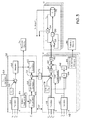
- FIG. 3 Further details of master bus power control unit 20 and field controllers 40 are illustrated in FIG. 3 in accordance with one embodiment of the present technique.
- Various signals described above are communicated between master bus power control unit 20 and field controllers 40 via a communication link 52.
- the voltage from output bus 22 is input to master bus power control 20 and transformed, as indicated in block 54.
- This transformed voltage is combined with a reference voltage 56 and a reference voltage correction factor 58, which are input into an integrator circuit 60.
- reference voltage 56 is 115 Vrms, however, other voltages may be utilized in accordance with the present techniques.
- Integrator 60 outputs a bus voltage correction factor 62 which is combined with a power balance correction factor 68, as described below.
- a system configuration module 64 may receive or contain configuration data regarding the generators and the buses.
- the system configuration module 64 may include the status of the various generators, such as which generators are active or inactive, and which are running in parallel or in an independent fashion, for example. As discussed below, a generator may be removed from parallel operation due to loading issues or operating error, to operate independently from other generators, or for other reasons.
- a target value control module 66 receives data from system configuration module 64, as well as the apparent power from each generator 32, and provides a power balance correction factor 68 for each generator.
- System configuration module 64 may also output a signal to various protection circuitries 74, which may include switches 44 and 46, to activate or deactivate the power generation system 10 or individual generator groups 28 or the system.
- a power balance correction factor 68 is provided to each generator 32, based on the difference between or deviation of the actual output power of each generator 32 from the desired output power of that generator, to reduce or increase the power output by that generator in order to more closely conform with the average power output of all generators 32 in parallel operation.
- each power balance correction factor 68 is based on the particular output characteristics of that generator. A generator 32 that is outputting power of a greater magnitude than the average of a group of generators may result in application of a power balance correction factor 68 that effects a reduction in the output power produced by that particular generator.
- a generator 32 that is producing less power than the group average could receive a power balance correction factor 68 that results in an increase in the power output of that generator.
- a power balance correction factor 68 is applied to each generator 32 to reduce deviation of the output power of each generator 32 from the desired output power level for that generator.
- Each power balance correction factor 68 and the bus voltage correction factor 62 are combined, as indicated in summation block 70, to produce a correction command signal or factor 72 for the respective generator 32.
- the correction or adjustment signal 72 is input from the master bus power control unit 20 to a field controller 40, and combined with a transformed output voltage, as indicated in block 76, and a local reference voltage 78. This combined signal may then be fed to a voltage regulator 80.
- output current of a particular generator 32 is input to its respective field controller 40 and transformed as indicated in block 82.
- a processing block 84 receives both the transformed voltage and transformed current to calculate the apparent power 86 of the generator 32, which is input to the target value control module 66, as described above.
- the input of the updated apparent power of each generator 32 to target value control module 66 facilitates the comparison of the output power of each generator 32 to a desired level, such as an average level. Further, it allows for simultaneous or near-simultaneous correction or adjustment of each individual output power via a correction or adjustment signal 72.
- the transformed current may also be used to provide a load feed forward signal 88 that is combined with an output signal from voltage regulator 80 to improve its dynamic performance at summation block 90.
- the combined signal may be output from block 90 to a field regulator 92.
- voltage regulator 80 and field regulator 92 may also include various error compensation or integration techniques that may be desirable for a given application.
- field controllers 40 may also include protection and ground fault interrupter modules 94 to control various protection circuitry 96 of the system 10.
- a signal from each field regulator 92 is transmitted from field controller 40 to an inverter 38 associated with a respective generator 32.
- the output of inverter 38 affects the back EMF on exciter coil 36 that, in turn, affects the output power of generator 32.
- the signal output from field controller 40 to the inverter 38 directly impacts the output power of each generator 32. Further, feedback is provided from exciter 36 to inverter 38 for closed loop control of the magnetic field.
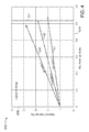
- FIGS. 4-7 illustrate graphs depicting the output power of several exemplary generators.
- the apparent power of a generator is the vector sum of a real or active power component and a reactive power component.
- the real power produced by the exemplary generators is measured along the horizontal axis, while the reactive power is measured along the vertical axis.
- the resulting apparent power is represented by the length of the vectors 108, 110, and 112 in FIG. 4.
- three exemplary generators may produce equal individual apparent output powers 108, 110, and 112. It will be noted that the present apparent output powers 108, 110, and 112 are based on a load lagging power factor of 0.95.
- a load lagging power factor of 0.95 it will appreciate that, holding the apparent power constant, decreasing the power factor increases the reactive power component and decreases the real power component of the generated power.
- an adjustment signal may be applied to Generator 1, such as via a field controller 40, to increase the apparent power 108 produced by the generator.
- an adjustment signal may be applied to Generator 3 to reduce the apparent power 112 produced by this generator.
- the real power components of output powers 108, 110, 112 may be balanced, as provided in FIG. 5.
- balancing power may include operating one or more generators at one power output level, one or more generators at a second output level, or operating each generator at a different output level.
- one or more of the generators may be disconnected from the system and operated independently of the parallel generators, or deactivated, and correction signals may be applied to the remaining parallel generators to compensate for the power not being produced by the disconnected generators. As will be appreciated, this would allow one or more of the generators to power an independent load or be serviced without impacting the system as a whole, and also provides redundancy in case a generator unexpectedly fails.
- FIG. 6 illustrates the apparent powers produced by several generators at a power factor 0.70.
- the real power is measured along horizontal axis 120 and the reactive power is measured along vertical axis 122.
- Generators 1, 2, and 3 produce apparent output powers 124, 126, and 128, respectively.
- Individual correction signals maybe applied to each of Generators 1, 2, and 3 to increase or decrease the apparent output power produced by these generators, as needed, to balance the magnitudes of these output powers along the curve 130, as provided in graph 132 of FIG. 7.
- Inverter 38 may be PWM (pulse width modulated) inverter.
Landscapes
- Engineering & Computer Science (AREA)
- Power Engineering (AREA)
- Supply And Distribution Of Alternating Current (AREA)
- Control Of Eletrric Generators (AREA)
Abstract
Description
- The present invention generally relates to electrical power generation systems. More particularly, the present invention relates to a technique for adjusting power output by each of a plurality of electrical generators driven by a single prime mover.
- Electrical power generation systems are employed in a number of diverse applications, including aviation, manufacturing, and commercial energy production, to name just a few. As will be appreciated, these systems are generally adapted to convert mechanical power to electrical power that may be used to operate one or more electrical devices or systems requiring such power. Generally, these power generation systems include one or more generators, each generator having a stator and a rotor that rotates with respect to the stator. Such power generation systems also typically include one or more prime movers that supply mechanical power to the rotors. In the case of aviation, for example, prime movers are often gas turbine engines of an aircraft. In some generators, a magnetic field is projected from rotor poles within the rotor and the rotation of the rotor and the magnetic field induces alternating electrical current in the windings of the stator that may be used to power electrical devices. While many generators are produced in which the rotor is configured to rotate within the stator, one skilled in the art will also appreciate that generators may be configured to allow the rotor to rotate about an interior stator.
- In the case of a power generation system having multiple generators, it may be desirable to control or balance the electrical power contribution of each generator, including its real and reactive components. Often, when such control is envisaged, a power generation system will include a separate prime mover that provides mechanical power to each generator. The use of independent prime movers for each generator allows the power output to be controlled via adjustment to the applied power of the prime mover and the relative phase angle of the alternating power between the generators. While the coupling of a single generator to a prime mover may be adequate for certain uses, such an arrangement has limitations. For instance, an aircraft includes a finite number of prime movers to drive electrical generators. If the aircraft included two gas turbine engines, only two electrical generators connected to the same grid could be driven by the turbines. If additional generators were needed, it would be possible to couple additional generators to a prime mover. However, as will be appreciated, the coupling of multiple generators to a single prime mover would preclude control of the power output by the generators via adjustments to the common prime mover or the mechanically coupled and non-adjustable phase angles of the generators. Further, the inability to make such adjustments aversely impacts the power rating of a given power generation system.
- There exists, therefore, a need for an improved power balancing and adjustment technique that would allow independent adjustment of output power, both real and reactive components, produced by each of a plurality of generators driven by a common prime mover.
- Certain aspects commensurate in scope with the originally claimed invention are set forth below. It should be understood that these aspects are presented merely to provide the reader with a brief summary of certain forms the invention might take and that these aspects are not intended to limit the scope of the invention. Indeed, the invention may encompass a variety of aspects that may not be set forth below.
- Embodiments of the present technique generally relate to synchronous power generator systems and methods for balancing individual power outputs, including balancing the real, reactive, or apparent forms of these outputs, between generators within such systems. Certain embodiments of the presently disclosed technique facilitate balancing of power between multiple generators and independent adjustment of the output power produced by one of a plurality of generators driven by a single prime mover. In some embodiments, such as if the generators are of the same rating, balancing may be performed in order to equalize the output power of each generator of the plurality such that the output power produced by a single generator closely approximates the average output power of each generator of the plurality. However, in other embodiments, power balancing may be performed to establish a first output power from one generator driven by a prime mover and to establish a second, different, output power from another generator driven by the same prime mover.
- These and other features, aspects, and advantages of embodiments of the present invention will become better understood when the following detailed description of embodiments provided by way of example only is read with reference to the accompanying drawings in which like characters represent like parts throughout the drawings, wherein:
- FIG. 1 is a block diagram illustrating an exemplary power generation system having a plurality of synchronous generators in accordance with one embodiment of the present technique;
- FIG. 2 is a block diagram illustrating additional details and components of the generators and the power system provided in FIG. 1 in accordance with one embodiment of the present technique;
- FIG. 3 is a block diagram illustrating further exemplary details with respect to control units depicted in FIGS. 1 and 2;
- FIG. 4 is a graph illustrating exemplary apparent power output vectors of each of a plurality of generators;
- FIG. 5 is a graph depicting the balancing of real output power of the plurality of generators of FIG. 4 in accordance with certain aspects of the present technique;
- FIG. 6 is a graph illustrating alternative exemplary apparent power output vectors of several generators; and
- FIG. 7 is a graph depicting the balancing of apparent output power of the generators of FIG. 6 in accordance with certain aspects of the present technique.
- One or more specific embodiments of the present technique will be described below. In an effort to provide a concise description of these embodiments, not all features of an actual implementation are described in the specification. It should be appreciated that in the development of any such actual implementation, as in any engineering or design project, numerous implementation-specific decisions will be made to achieve the developers' specific goals, such as compliance with system-related and business-related constraints, which can vary from one implementation to another. Moreover, it should be appreciated that such a development effort can be complex and time consuming, but would remain a routine undertaking of design, fabrication, and manufacture for those of ordinary skill having the benefit of this disclosure. It should be noted that illustrated embodiments of the present technique throughout this text represent a general case.
- Turning now to the figures, a block diagram illustrating an exemplary
power generation system 10 in accordance with one embodiment of the present technique is provided in FIG. 1. Thesystem 10 includes a plurality ofsynchronous generators 14 coupled to and driven by a single prime mover, such asturbine 12. Particularly,turbine 12 provides mechanical power togenerators 14 via a mechanical power divider, such asgear box 16. As will be appreciated by one skilled in the art,generators 14 convert the mechanical input power received fromturbine 12 viagear box 16 to electrical output power. As will be appreciated, thegenerators 14 may have equivalent or different power ratings in various embodiments. - The
system 10 also includesfield control units 18, each of which is associated with agenerator 14, and a master buspower control unit 20 coupled to thefield control units 18. The power output bygenerators 14 is transmitted to anoutput bus 22 that may provide power to a variety of other electrical devices or systems. Afeedback bus 24 receives signals fromsensors 25 coupled to theoutput bus 22, and transmits these signals to master buspower control unit 20. As explained in greater detail below, master buspower control unit 20 utilizes this information and applies correction or adjustment signals to thefield control units 18 via acontrol bus 26 to regulate the active (i.e., real) and reactive power output by each generator in an independent fashion. - It should be noted that the present system might find a wide range of uses and applications. For instance, the present system may be advantageously employed in connection with an aircraft electrical system. However, other implementations are also envisaged, including use in the oil and gas industry, ship power generation, directed energy defense systems, and radar systems, to name a few. Further, it will be appreciated that, although the present
exemplary system 10 includes three synchronous generators of the same ratings, other systems may include a different number of generators, such as six, eight, or the like. Indeed, any systems including a plurality of generators may be employed in full accordance with the present technique. Still further, while the present embodiment includes three generators providing output power to asingle output bus 22, other embodiments may include multiple output busses that separately and independently receive output power from several sub groupings of generators. Additionally, one ormore generators 14 may have loads attached to them independent ofoutput bus 22. In such an instance, thefield control units 18 provide local control for independent operation of agenerator 14, while the master buspower control unit 20 facilitates parallel operation of the generators. - Additional details of the
exemplary system 10 may be more clearly described and understood with reference to FIG. 2. Notably,system 10 includes a plurality ofgenerator groups 28, each of which includes agenerator system 14 and afield control unit 18. Thegenerator groups 28 produce electrical power that may be used to operate numerous devices or systems, such asload 30. In the illustrated embodiment,generator system 14 includes agenerator 32, arotating rectifier 34, and anexciter 36. Thegenerator groups 28 may be one of a number of various generator types, including a brushless excited synchronous generator, a wound field synchronous generator, a synchronous generator with an excitation circuit, a homo-polar synchronous generator, to name but a few. - Further, each
field control unit 18 includes aninverter 38 and afield controller 40. Eachfield controller 40 is configured to receive various input signals and to produce an output signal that controls abrushless exciter 36. As will be appreciated, thecontrol unit 18 can increase or decrease back EFM on the exciter coil to control internal field strength and output power produced bygenerator 32. Characteristics of the output power produced bygenerator 32 are sensed via voltage sensors Va, Vb, and Vc, and current sensors Ia, Ib, Ic, and In. These sensed characteristics may then be input tofield controller 40. Thefield controller 40 is also configured to receive a control signal, which may include a status signal and a correction signal as discussed in greater detail below, from master buspower control unit 20 and a shunt voltage Vsh from asensor 42.Sensors 42 measure AC current produced bygenerator groups 28 and detect current imbalance between these groups. This information may be input to either or both of master buspower control unit 20 and thefield controllers 40 to facilitate application of a correction or command signal to reduce such an imbalance. Thefield controller 40 processes these signals to generate a command signal to adjust the power output ofgenerator 32. - The power output by each
generator group 28 is supplied to theoutput bus 22, as discussed above. The characteristics of the aggregate power transmitted over the bus, including IR, IS, IT, VR, VS, and VT, are sensed and input to master buspower control unit 20. As discussed below, thepower control unit 20 generates a status or control signal that is applied to eachfield controller 40. Further, thepower control unit 20 may also output a control signal to one or more protective circuits, such asswitches 44 and 46. - Further details of master bus
power control unit 20 andfield controllers 40 are illustrated in FIG. 3 in accordance with one embodiment of the present technique. Various signals described above are communicated between master buspower control unit 20 andfield controllers 40 via a communication link 52. The voltage fromoutput bus 22 is input to masterbus power control 20 and transformed, as indicated in block 54. This transformed voltage is combined with a reference voltage 56 and a reference voltage correction factor 58, which are input into an integrator circuit 60. In one embodiment, reference voltage 56 is 115 Vrms, however, other voltages may be utilized in accordance with the present techniques. Integrator 60 outputs a bus voltage correction factor 62 which is combined with a power balance correction factor 68, as described below. - A system configuration module 64 may receive or contain configuration data regarding the generators and the buses. For instance, the system configuration module 64 may include the status of the various generators, such as which generators are active or inactive, and which are running in parallel or in an independent fashion, for example. As discussed below, a generator may be removed from parallel operation due to loading issues or operating error, to operate independently from other generators, or for other reasons. A target value control module 66 receives data from system configuration module 64, as well as the apparent power from each
generator 32, and provides a power balance correction factor 68 for each generator. System configuration module 64 may also output a signal to various protection circuitries 74, which may includeswitches 44 and 46, to activate or deactivate thepower generation system 10 orindividual generator groups 28 or the system. - In some embodiments, it may be desirable to equalize the power generated by each
generator 32. In such embodiments, a power balance correction factor 68 is provided to eachgenerator 32, based on the difference between or deviation of the actual output power of eachgenerator 32 from the desired output power of that generator, to reduce or increase the power output by that generator in order to more closely conform with the average power output of allgenerators 32 in parallel operation. As will be appreciated, each power balance correction factor 68 is based on the particular output characteristics of that generator. Agenerator 32 that is outputting power of a greater magnitude than the average of a group of generators may result in application of a power balance correction factor 68 that effects a reduction in the output power produced by that particular generator. Likewise, agenerator 32 that is producing less power than the group average could receive a power balance correction factor 68 that results in an increase in the power output of that generator. In other embodiments, it may be desirable to operate onegenerator 32 to produce output power that is higher or lower than that produced by theother generators 32. In these embodiments, a power balance correction factor 68 is applied to eachgenerator 32 to reduce deviation of the output power of eachgenerator 32 from the desired output power level for that generator. - Each power balance correction factor 68 and the bus voltage correction factor 62 are combined, as indicated in summation block 70, to produce a correction command signal or factor 72 for the
respective generator 32. The correction or adjustment signal 72 is input from the master buspower control unit 20 to afield controller 40, and combined with a transformed output voltage, as indicated in block 76, and alocal reference voltage 78. This combined signal may then be fed to a voltage regulator 80. - Additionally, output current of a
particular generator 32 is input to itsrespective field controller 40 and transformed as indicated inblock 82. Aprocessing block 84 receives both the transformed voltage and transformed current to calculate the apparent power 86 of thegenerator 32, which is input to the target value control module 66, as described above. The input of the updated apparent power of eachgenerator 32 to target value control module 66 facilitates the comparison of the output power of eachgenerator 32 to a desired level, such as an average level. Further, it allows for simultaneous or near-simultaneous correction or adjustment of each individual output power via a correction or adjustment signal 72. - The transformed current may also be used to provide a load feed forward signal 88 that is combined with an output signal from voltage regulator 80 to improve its dynamic performance at
summation block 90. The combined signal may be output fromblock 90 to a field regulator 92. As will be appreciated, voltage regulator 80 and field regulator 92 may also include various error compensation or integration techniques that may be desirable for a given application. It should be noted that, in certain embodiments,field controllers 40 may also include protection and ground fault interrupter modules 94 to controlvarious protection circuitry 96 of thesystem 10. - A signal from each field regulator 92 is transmitted from
field controller 40 to aninverter 38 associated with arespective generator 32. As will be appreciated, the output ofinverter 38 affects the back EMF onexciter coil 36 that, in turn, affects the output power ofgenerator 32. Thus, the signal output fromfield controller 40 to theinverter 38 directly impacts the output power of eachgenerator 32. Further, feedback is provided fromexciter 36 toinverter 38 for closed loop control of the magnetic field. - The present techniques allow for balancing of various power characteristics, including real power, reactive power, and apparent power. The balancing of power output by each of several generators may be made clear with reference to FIGS. 4-7. Notably, these figures illustrate graphs depicting the output power of several exemplary generators. As will be appreciated, the apparent power of a generator is the vector sum of a real or active power component and a reactive power component. In the graphs of FIGS. 4-7, the real power produced by the exemplary generators is measured along the horizontal axis, while the reactive power is measured along the vertical axis. The resulting apparent power is represented by the length of the
vectors - As illustrated in
graph 102 of FIG. 4, havingaxes apparent output powers apparent output powers output powers line 114. Such balancing may be achieved through the technique disclosed above. Particularly, an adjustment signal may be applied toGenerator 1, such as via afield controller 40, to increase theapparent power 108 produced by the generator. Similarly, an adjustment signal may be applied toGenerator 3 to reduce theapparent power 112 produced by this generator. Through use of such correction signals, the real power components ofoutput powers - Notably, in other embodiments, balancing power may include operating one or more generators at one power output level, one or more generators at a second output level, or operating each generator at a different output level. Further, in these or other embodiments, one or more of the generators may be disconnected from the system and operated independently of the parallel generators, or deactivated, and correction signals may be applied to the remaining parallel generators to compensate for the power not being produced by the disconnected generators. As will be appreciated, this would allow one or more of the generators to power an independent load or be serviced without impacting the system as a whole, and also provides redundancy in case a generator unexpectedly fails.
- If the power factor is reduced below a certain threshold, such as 0.80 or 0.85, it may be desirable to balance apparent output powers of several generators instead of balancing the real power components. For instance, FIG. 6 illustrates the apparent powers produced by several generators at a power factor 0.70. In
graph 118, the real power is measured alonghorizontal axis 120 and the reactive power is measured alongvertical axis 122.Generators apparent output powers output powers curve 130. Individual correction signals maybe applied to each ofGenerators curve 130, as provided ingraph 132 of FIG. 7. - In still further applications it may be desirable to balance the reactive power components of output power generated by a plurality of generators instead of balancing either the apparent power or real power components. Such reactive power balancing may find particular application in those situations in which the power factor falls below a certain threshold, such as 0.25 or 0.50, in which the reactive power components are larger than in the instance of higher power factors. As in the examples above, individual control signals can be applied to each of a plurality of generators to adjust the output power produced by the generators and to balance the reactive power components thereof.
Inverter 38 may be PWM (pulse width modulated) inverter. - While the present technique may be susceptible to various modifications and alternative forms, specific embodiments have been shown by way of example in the drawings and will be described in detail herein. However, it should be understood that the invention is not intended to be limited to the particular forms disclosed. Rather, the invention is to cover all modifications, equivalents and alternatives falling within the spirit and scope of the invention as defined by the following appended claims.
Claims (10)
- A method to balance power in a synchronous generator system (10), the method comprising:determining a first output power characteristic of a first synchronous generator (14) driven by a prime mover (12);comparing the first output power characteristic to a value derived from output power of a plurality of synchronous generators (14) to determine a deviation of the first output power characteristic from the value, wherein the plurality of synchronous generators (14) are driven by the prime mover (12); andproviding a correction signal (72) to the first synchronous generator (14) to adjust the output power thereof, wherein the correction signal is based on the first deviation.
- The method of claim 1, wherein determining the first output power characteristic comprises measuring real output power of the first synchronous generator (14).
- The method of claim 1, wherein determining the first output power characteristic comprises measuring apparent output power of the first synchronous generator (14).
- The method of claim 1, wherein the plurality of synchronous generators (14) includes the first synchronous generator (14).
- The method of claim 1, further comprising:determining an output power of each synchronous generator (14) of the plurality of synchronous generators (14) driven by the prime mover (12);comparing each output power of the respective synchronous generators (14) to the average output power of the plurality of synchronous generators (14) to determine a difference between each output power and the average output power; andproviding a correction signal (72) to each synchronous generator (14), wherein the respective correction signal (72) for each synchronous generator (14) depends upon the respective difference between the output power of the synchronous generator (14) and the average output power of the plurality of synchronous generators (14).
- The method of claim 1, wherein providing the correction signal (72) to the first synchronous generator (14) comprises providing the correction signal to a field controller (40) of the first synchronous generator (14) and an error compensation or integration process is performed following the provision of the correction signal.
- The method of claim 1, wherein the correction signal (72) includes a power balancing correction component (68) and a bus voltage correction component (62).
- The method of claim 1, wherein the value is an average output power of the plurality of synchronous generators.
- A synchronous generator system (10) comprising:a prime mover (12);a mechanical power divider (16) coupled to the prime mover (12) and configured to receive mechanical power therefrom;a plurality of synchronous generators (14) coupled to the mechanical power divider (16) to receive mechanical power therefrom;a control unit (20) coupled to the plurality of synchronous generators (14), the control unit configured to compare output power of each synchronous generator of the plurality of synchronous generators (14) to an average output power of the plurality of synchronous generators (14), and to provide an adjustment signal (72) to each synchronous generator (14), wherein the provision of the respective adjustment signal (72) effects modification of a deviation between the output power of each synchronous generator (14) and the average output power of the plurality of synchronous generators (14).
- The system of claim 9, wherein the control unit (20) is configured to compare real power of the synchronous generator (14) to the average real power of the plurality of synchronous generators (14).
Applications Claiming Priority (1)
| Application Number | Priority Date | Filing Date | Title |
|---|---|---|---|
| US11/303,726 US7319307B2 (en) | 2005-12-16 | 2005-12-16 | Power balancing of multiple synchronized generators |
Publications (1)
| Publication Number | Publication Date |
|---|---|
| EP1798836A1 true EP1798836A1 (en) | 2007-06-20 |
Family
ID=37908004
Family Applications (1)
| Application Number | Title | Priority Date | Filing Date |
|---|---|---|---|
| EP20060126125 Withdrawn EP1798836A1 (en) | 2005-12-16 | 2006-12-14 | Power balancing of multiple synchronized generators |
Country Status (7)
| Country | Link |
|---|---|
| US (2) | US7319307B2 (en) |
| EP (1) | EP1798836A1 (en) |
| JP (1) | JP5095196B2 (en) |
| KR (1) | KR101258710B1 (en) |
| CN (1) | CN1992465B (en) |
| CA (1) | CA2571300A1 (en) |
| IL (1) | IL180047A0 (en) |
Cited By (7)
| Publication number | Priority date | Publication date | Assignee | Title |
|---|---|---|---|---|
| CN101594102A (en) * | 2008-05-27 | 2009-12-02 | Abb瑞士有限公司 | The starting device that is used at least two synchronous machines |
| EP2163909A1 (en) * | 2008-09-10 | 2010-03-17 | Hamilton Sundstrand Corporation | Method of detecting a sustained parallel source condition |
| CN101826829A (en) * | 2009-03-03 | 2010-09-08 | 蓝水能源服务有限公司 | Semi-direct variable speed drive with N+1 availability |
| EP2806524A4 (en) * | 2012-01-20 | 2015-10-14 | Kyocera Corp | POWER SUPPLY SYSTEM AND POWER SUPPLY DEVICE |
| CN105041575A (en) * | 2015-07-10 | 2015-11-11 | 三一重型能源装备有限公司 | Multi-motor power generation device and wind power generation unit |
| EP2128956B1 (en) * | 2008-04-20 | 2017-06-07 | Hamilton Sundstrand Corporation | Dual channel power generation system |
| US20220069587A1 (en) * | 2020-09-02 | 2022-03-03 | General Electric Company | Load-sharing with interconnected power generation |
Families Citing this family (32)
| Publication number | Priority date | Publication date | Assignee | Title |
|---|---|---|---|---|
| ITTO20050712A1 (en) * | 2005-10-07 | 2007-04-08 | Ansaldo Ricerche S P A | ELECTRICITY GENERATION SYSTEM |
| ITTO20050711A1 (en) * | 2005-10-07 | 2007-04-08 | Ansaldo Ricerche S P A | RECONFIGURABLE ENERGY DISTRIBUTION NETWORK |
| JP2007205166A (en) * | 2006-01-30 | 2007-08-16 | Kokusan Denki Co Ltd | Engine control device |
| US7423412B2 (en) * | 2006-01-31 | 2008-09-09 | General Electric Company | Method, apparatus and computer program product for injecting current |
| JP4719760B2 (en) * | 2008-03-25 | 2011-07-06 | 株式会社日立製作所 | Control method and system for distributed power supply group |
| US20090322085A1 (en) * | 2008-06-18 | 2009-12-31 | Renaud Regis P | Method and apparatus for enhanced wind turbine design |
| US7847423B1 (en) * | 2008-06-23 | 2010-12-07 | Otto Farkas | Backup power system |
| US20090323256A1 (en) | 2008-06-25 | 2009-12-31 | Errera Michael R | Interface for system for generating electric power |
| AU2010319848B2 (en) * | 2009-10-28 | 2015-02-05 | Cummins Power Generation Ip, Inc. | Management techniques for electric power generation equipment |
| JP5716183B2 (en) * | 2010-11-02 | 2015-05-13 | 三菱日立パワーシステムズ株式会社 | Power generation system and power generation system control method |
| RU2518905C2 (en) * | 2011-05-17 | 2014-06-10 | Хонда Мотор Ко., Лтд. | Control device for providing parallel operation of vst generator |
| US8640534B2 (en) | 2011-08-22 | 2014-02-04 | Bendix Commercial Vehicle Systems Llc | Mounting method and device for tire pressure monitoring sensor |
| US8907510B2 (en) * | 2012-03-09 | 2014-12-09 | General Electric Company | Method and systems for operating a wind turbine |
| EP2672624B1 (en) * | 2012-06-05 | 2014-10-29 | Siemens Aktiengesellschaft | Current controller and generator system |
| WO2014143218A1 (en) | 2013-03-13 | 2014-09-18 | Rolls-Royce North American Technologies, Inc. | Gas turbine engine and electrical system comprising electrical buses |
| EP2971699B8 (en) | 2013-03-15 | 2020-01-15 | Rolls-Royce Corporation | Lifing and performance optimization limit management for turbine engine |
| US8772954B1 (en) * | 2013-04-15 | 2014-07-08 | Caterpillar Inc. | Power balancing for a dual generator single DC link configuration for electric drive propulsion system |
| RU2580843C2 (en) * | 2013-11-13 | 2016-04-10 | Российская Федерация, От Имени Которой Выступает Министерство Промышленности И Торговли Российской Федерации | Device for obtaining frequency adjusted voltage at output of multiphase ac generator with constant rotation frequency of shaft |
| US9154067B2 (en) | 2013-12-19 | 2015-10-06 | Kohler Co. | Torque sharing on paralleled generators |
| GB201403178D0 (en) | 2014-02-24 | 2014-04-09 | Rolls Royce Plc | Electrical power generator for a gas turbine engine |
| US20160363950A1 (en) * | 2015-06-15 | 2016-12-15 | Innovari, Inc. | Resource management for optimized grid operations |
| US10518863B2 (en) * | 2016-04-22 | 2019-12-31 | Rolls-Royce Plc | Aircraft electrical network |
| US11108242B2 (en) | 2016-12-05 | 2021-08-31 | Ge Aviation Systems, Llc | Method and system for load sharing among multiple DC generators |
| US10224848B2 (en) * | 2017-01-30 | 2019-03-05 | Pratt & Whitney Canada Corp. | Method and system for synchronizing generators |
| EP3487060A1 (en) * | 2017-11-17 | 2019-05-22 | ABB Schweiz AG | Method and control system for controlling a voltage source converter using power-synchronisation control |
| US11264801B2 (en) * | 2018-02-23 | 2022-03-01 | Schlumberger Technology Corporation | Load management algorithm for optimizing engine efficiency |
| WO2019183428A1 (en) | 2018-03-22 | 2019-09-26 | Continental Motors, Inc. | Engine ignition timing and power supply system |
| WO2020172578A1 (en) | 2019-02-22 | 2020-08-27 | Basler Electric Company | Advanced cross-current compensation system and method for enhancing reactive current sharing |
| CN109921468B (en) * | 2019-04-12 | 2023-08-18 | 福建广通机电科技有限公司 | Parallel operation control method for small single-phase generator set |
| CN112821417B (en) * | 2021-01-05 | 2023-05-30 | 中车株洲电力机车研究所有限公司 | A generator output power control method, device, storage medium and equipment |
| CN117060446B (en) * | 2023-08-22 | 2024-02-13 | 湖南工商大学 | Distributed master-slave self-synchronous control method for three-phase series energy storage system |
| CN117792168B (en) * | 2024-02-28 | 2024-05-07 | 山西汇达电信设备有限公司 | Generator configuration method and system |
Citations (5)
| Publication number | Priority date | Publication date | Assignee | Title |
|---|---|---|---|---|
| GB871056A (en) * | 1958-01-23 | 1961-06-21 | Jack & Heintz Inc | Improvements in or relating to generating systems |
| GB2101691A (en) * | 1981-07-07 | 1983-01-19 | Snam Progetti | Exploitation of wind energy for producing electrical power |
| US5083039A (en) * | 1991-02-01 | 1992-01-21 | U.S. Windpower, Inc. | Variable speed wind turbine |
| US20050012339A1 (en) * | 2003-05-07 | 2005-01-20 | Mikhail Amir S. | Variable speed distributed drive train wind turbine system |
| WO2006010190A1 (en) * | 2004-07-30 | 2006-02-02 | Gerald Hehenberger | Power train for a wind power plant |
Family Cites Families (19)
| Publication number | Priority date | Publication date | Assignee | Title |
|---|---|---|---|---|
| US1699128A (en) * | 1926-05-28 | 1929-01-15 | Gen Electric | Control of distant power stations |
| US2008506A (en) * | 1932-02-18 | 1935-07-16 | Gen Electric | Alternating current distribution system |
| US2465826A (en) * | 1947-02-17 | 1949-03-29 | Frederick L Wolf | Broadcast system for producing simultaneous alarm signals in a plurality of telephone stations |
| JPS49128209A (en) * | 1973-04-13 | 1974-12-09 | ||
| JPS5035612A (en) * | 1973-08-03 | 1975-04-04 | ||
| JPS6020731A (en) * | 1983-07-14 | 1985-02-02 | 株式会社明電舎 | Reactive cross current compensator |
| US4460834A (en) * | 1983-08-29 | 1984-07-17 | Power Group International Corp. | Uninterruptible power system |
| JPS6268025A (en) * | 1985-09-17 | 1987-03-27 | 三菱電機株式会社 | Load sharing device |
| US4757249A (en) * | 1987-06-15 | 1988-07-12 | Deere & Company | Vehicle dual electrical system |
| US5311062A (en) * | 1991-04-04 | 1994-05-10 | Otto Farkas | Transient-free synchronous electrical power machine |
| JP2716602B2 (en) * | 1991-06-26 | 1998-02-18 | 三菱電機株式会社 | Generator parallel operation system |
| JPH07327319A (en) * | 1994-05-31 | 1995-12-12 | Meidensha Corp | Erroneous function preventive circuit for reverse power relay at transition of load |
| US5646458A (en) * | 1996-02-22 | 1997-07-08 | Atlas Energy Systems, Inc. | Uninterruptible power system with a flywheel-driven source of standby power |
| US5734255A (en) * | 1996-03-13 | 1998-03-31 | Alaska Power Systems Inc. | Control system and circuits for distributed electrical power generating stations |
| US6218813B1 (en) * | 1999-09-30 | 2001-04-17 | Rockwell Technologies, Llc | Cross current compensation system and method |
| US6653821B2 (en) * | 2001-06-15 | 2003-11-25 | Generac Power Systems, Inc. | System controller and method for monitoring and controlling a plurality of generator sets |
| US7016793B2 (en) * | 2003-10-01 | 2006-03-21 | General Electric Company | Method and apparatus for anti-islanding protection of distributed generations |
| US7161257B2 (en) * | 2004-03-08 | 2007-01-09 | Ingersoll-Rand Energy Systems, Inc. | Active anti-islanding system and method |
| US7091702B2 (en) * | 2004-12-07 | 2006-08-15 | Hamilton Sundstrand Corporation | Digital real and reactive load division control |
-
2005
- 2005-12-16 US US11/303,726 patent/US7319307B2/en not_active Expired - Fee Related
-
2006
- 2006-12-13 IL IL180047A patent/IL180047A0/en not_active IP Right Cessation
- 2006-12-14 EP EP20060126125 patent/EP1798836A1/en not_active Withdrawn
- 2006-12-14 CA CA 2571300 patent/CA2571300A1/en not_active Abandoned
- 2006-12-15 CN CN2006100640624A patent/CN1992465B/en not_active Expired - Fee Related
- 2006-12-15 KR KR1020060128762A patent/KR101258710B1/en not_active Expired - Fee Related
- 2006-12-18 JP JP2006339754A patent/JP5095196B2/en not_active Expired - Fee Related
-
2007
- 2007-11-20 US US11/943,371 patent/US7521902B2/en not_active Expired - Fee Related
Patent Citations (6)
| Publication number | Priority date | Publication date | Assignee | Title |
|---|---|---|---|---|
| GB871056A (en) * | 1958-01-23 | 1961-06-21 | Jack & Heintz Inc | Improvements in or relating to generating systems |
| GB2101691A (en) * | 1981-07-07 | 1983-01-19 | Snam Progetti | Exploitation of wind energy for producing electrical power |
| US5083039A (en) * | 1991-02-01 | 1992-01-21 | U.S. Windpower, Inc. | Variable speed wind turbine |
| US5083039B1 (en) * | 1991-02-01 | 1999-11-16 | Zond Energy Systems Inc | Variable speed wind turbine |
| US20050012339A1 (en) * | 2003-05-07 | 2005-01-20 | Mikhail Amir S. | Variable speed distributed drive train wind turbine system |
| WO2006010190A1 (en) * | 2004-07-30 | 2006-02-02 | Gerald Hehenberger | Power train for a wind power plant |
Cited By (15)
| Publication number | Priority date | Publication date | Assignee | Title |
|---|---|---|---|---|
| EP2128956B1 (en) * | 2008-04-20 | 2017-06-07 | Hamilton Sundstrand Corporation | Dual channel power generation system |
| EP2128973A1 (en) * | 2008-05-27 | 2009-12-02 | ABB Schweiz AG | Starting device for at least two synchronous machines |
| CN101594102A (en) * | 2008-05-27 | 2009-12-02 | Abb瑞士有限公司 | The starting device that is used at least two synchronous machines |
| US8102132B2 (en) | 2008-05-27 | 2012-01-24 | Abb Schweiz Ag | Starting apparatus for at least two synchronous machines |
| RU2489789C2 (en) * | 2008-05-27 | 2013-08-10 | Абб Швайц Аг | Starting apparatus for synchronous machines |
| CN101594102B (en) * | 2008-05-27 | 2013-10-16 | Abb瑞士有限公司 | Starting apparatus for at least two synchronous machines |
| EP2163909A1 (en) * | 2008-09-10 | 2010-03-17 | Hamilton Sundstrand Corporation | Method of detecting a sustained parallel source condition |
| US8120206B2 (en) | 2008-09-10 | 2012-02-21 | Hamilton Sundstrand Corporation | Method of detecting a sustained parallel source condition |
| CN101826829A (en) * | 2009-03-03 | 2010-09-08 | 蓝水能源服务有限公司 | Semi-direct variable speed drive with N+1 availability |
| EP2806524A4 (en) * | 2012-01-20 | 2015-10-14 | Kyocera Corp | POWER SUPPLY SYSTEM AND POWER SUPPLY DEVICE |
| US9768618B2 (en) | 2012-01-20 | 2017-09-19 | Kyocera Corporation | Power supply system and power source apparatus |
| CN105041575A (en) * | 2015-07-10 | 2015-11-11 | 三一重型能源装备有限公司 | Multi-motor power generation device and wind power generation unit |
| US20220069587A1 (en) * | 2020-09-02 | 2022-03-03 | General Electric Company | Load-sharing with interconnected power generation |
| EP3965250A1 (en) * | 2020-09-02 | 2022-03-09 | General Electric Company | Load-sharing with interconnected power generation |
| US12218510B2 (en) * | 2020-09-02 | 2025-02-04 | Ge Infrastructure Technology Llc | Load-sharing with interconnected power generation |
Also Published As
| Publication number | Publication date |
|---|---|
| US7521902B2 (en) | 2009-04-21 |
| US7319307B2 (en) | 2008-01-15 |
| IL180047A0 (en) | 2007-10-31 |
| CN1992465B (en) | 2012-09-05 |
| KR20070064410A (en) | 2007-06-20 |
| CA2571300A1 (en) | 2007-06-16 |
| JP5095196B2 (en) | 2012-12-12 |
| KR101258710B1 (en) | 2013-04-26 |
| CN1992465A (en) | 2007-07-04 |
| US20080073979A1 (en) | 2008-03-27 |
| JP2007166897A (en) | 2007-06-28 |
| US20070139019A1 (en) | 2007-06-21 |
Similar Documents
| Publication | Publication Date | Title |
|---|---|---|
| US7319307B2 (en) | Power balancing of multiple synchronized generators | |
| CN110114951B (en) | Power supply system | |
| US6838860B2 (en) | Power generating system including permanent magnet generator and shunt AC regulator | |
| CN103792852B (en) | Voltage regulator for emulating the reactive power in parallel electrical power generation system and method | |
| JP6700102B2 (en) | Power converter | |
| JP5844803B2 (en) | Method for supplying electrical energy to a three-phase AC voltage network | |
| JP2004532595A (en) | How to operate a wind turbine | |
| KR20140019019A (en) | Power conversion apparatus directed to combined-cycle power generation system | |
| CN106716761A (en) | Genset power control in power system | |
| WO2005002038A1 (en) | Motor drive system | |
| EP1638199A1 (en) | Motor drive system | |
| Nozari et al. | Sensorless synchronous motor drive for use on commercial transport airplanes | |
| US10404198B2 (en) | Controlling the energy flow from an electrical machine with unbalanced impedance | |
| CN112087166A (en) | Alternating current-direct current hybrid double-fed asynchronous full-electric ship electric propulsion system and control method | |
| US12483172B2 (en) | Concentrated-winding electrical machines with floating exciter | |
| US11855459B2 (en) | Method for three-phase supply into an alternating voltage network, and three-phase inverter | |
| JP5016004B2 (en) | Method and apparatus for detecting isolated operation of power generation equipment | |
| JP6743522B2 (en) | Power supply system and power supply method | |
| US11936286B2 (en) | Systems and methods for power generation control | |
| US10840839B1 (en) | Method and system for independent-speed-variable-frequency-generator-based power system voltage regulation | |
| KR102805221B1 (en) | Generator exciter control system equipped with Error Compensation Control algorithm specialized for parallel operation | |
| Drozdowski et al. | Natural fault tolerance of a nine-phase induction motor drive operating at variable frequency and switched supply sequence | |
| Hall et al. | Nonlinear, Bidirectional Control of Three-Stage Aircraft Generators | |
| CN121909149A (en) | Ship power management method and device based on power grid forming type shaft generator and ship | |
| Adefajo et al. | Voltage control on an uninhabited autonomous vehicle electrical distribution system |
Legal Events
| Date | Code | Title | Description |
|---|---|---|---|
| PUAI | Public reference made under article 153(3) epc to a published international application that has entered the european phase |
Free format text: ORIGINAL CODE: 0009012 |
|
| AK | Designated contracting states |
Kind code of ref document: A1 Designated state(s): AT BE BG CH CY CZ DE DK EE ES FI FR GB GR HU IE IS IT LI LT LU LV MC NL PL PT RO SE SI SK TR |
|
| AX | Request for extension of the european patent |
Extension state: AL BA HR MK YU |
|
| 17P | Request for examination filed |
Effective date: 20071220 |
|
| 17Q | First examination report despatched |
Effective date: 20080124 |
|
| AKX | Designation fees paid |
Designated state(s): CH DE FR GB IT LI |
|
| STAA | Information on the status of an ep patent application or granted ep patent |
Free format text: STATUS: THE APPLICATION IS DEEMED TO BE WITHDRAWN |
|
| 18D | Application deemed to be withdrawn |
Effective date: 20140701 |