EP1798755A2 - Containment structure for light source capsules operating at other than the pressure of a surrounding gas - Google Patents
Containment structure for light source capsules operating at other than the pressure of a surrounding gas Download PDFInfo
- Publication number
- EP1798755A2 EP1798755A2 EP06125245A EP06125245A EP1798755A2 EP 1798755 A2 EP1798755 A2 EP 1798755A2 EP 06125245 A EP06125245 A EP 06125245A EP 06125245 A EP06125245 A EP 06125245A EP 1798755 A2 EP1798755 A2 EP 1798755A2
- Authority
- EP
- European Patent Office
- Prior art keywords
- lamp
- envelope
- light source
- containment vessel
- helix
- Prior art date
- Legal status (The legal status is an assumption and is not a legal conclusion. Google has not performed a legal analysis and makes no representation as to the accuracy of the status listed.)
- Granted
Links
- 239000002775 capsule Substances 0.000 title claims abstract description 47
- 238000010891 electric arc Methods 0.000 claims abstract description 15
- 239000011521 glass Substances 0.000 claims abstract description 14
- 239000007789 gas Substances 0.000 claims description 13
- 239000007787 solid Substances 0.000 claims description 8
- XKRFYHLGVUSROY-UHFFFAOYSA-N Argon Chemical compound [Ar] XKRFYHLGVUSROY-UHFFFAOYSA-N 0.000 claims description 4
- 239000000919 ceramic Substances 0.000 claims description 3
- 239000000463 material Substances 0.000 claims description 3
- 229910052786 argon Inorganic materials 0.000 claims description 2
- 229910052754 neon Inorganic materials 0.000 claims description 2
- GKAOGPIIYCISHV-UHFFFAOYSA-N neon atom Chemical compound [Ne] GKAOGPIIYCISHV-UHFFFAOYSA-N 0.000 claims description 2
- 229910001507 metal halide Inorganic materials 0.000 description 11
- 150000005309 metal halides Chemical class 0.000 description 11
- VYPSYNLAJGMNEJ-UHFFFAOYSA-N silicon dioxide Inorganic materials O=[Si]=O VYPSYNLAJGMNEJ-UHFFFAOYSA-N 0.000 description 9
- 239000010453 quartz Substances 0.000 description 7
- 230000000694 effects Effects 0.000 description 5
- DGAQECJNVWCQMB-PUAWFVPOSA-M Ilexoside XXIX Chemical compound C[C@@H]1CC[C@@]2(CC[C@@]3(C(=CC[C@H]4[C@]3(CC[C@@H]5[C@@]4(CC[C@@H](C5(C)C)OS(=O)(=O)[O-])C)C)[C@@H]2[C@]1(C)O)C)C(=O)O[C@H]6[C@@H]([C@H]([C@@H]([C@H](O6)CO)O)O)O.[Na+] DGAQECJNVWCQMB-PUAWFVPOSA-M 0.000 description 3
- 229910052708 sodium Inorganic materials 0.000 description 3
- 239000011734 sodium Substances 0.000 description 3
- 229910052721 tungsten Inorganic materials 0.000 description 3
- 239000010937 tungsten Substances 0.000 description 3
- IJGRMHOSHXDMSA-UHFFFAOYSA-N Atomic nitrogen Chemical compound N#N IJGRMHOSHXDMSA-UHFFFAOYSA-N 0.000 description 2
- PXHVJJICTQNCMI-UHFFFAOYSA-N Nickel Chemical compound [Ni] PXHVJJICTQNCMI-UHFFFAOYSA-N 0.000 description 2
- OAICVXFJPJFONN-UHFFFAOYSA-N Phosphorus Chemical compound [P] OAICVXFJPJFONN-UHFFFAOYSA-N 0.000 description 2
- 229910052736 halogen Inorganic materials 0.000 description 2
- 239000011261 inert gas Substances 0.000 description 2
- -1 tungsten halogen Chemical class 0.000 description 2
- 239000000654 additive Substances 0.000 description 1
- 239000005354 aluminosilicate glass Substances 0.000 description 1
- 230000004888 barrier function Effects 0.000 description 1
- 230000009286 beneficial effect Effects 0.000 description 1
- 239000005388 borosilicate glass Substances 0.000 description 1
- 230000009172 bursting Effects 0.000 description 1
- 239000011248 coating agent Substances 0.000 description 1
- 238000000576 coating method Methods 0.000 description 1
- 238000010276 construction Methods 0.000 description 1
- 230000003292 diminished effect Effects 0.000 description 1
- 230000008030 elimination Effects 0.000 description 1
- 238000003379 elimination reaction Methods 0.000 description 1
- 230000002708 enhancing effect Effects 0.000 description 1
- 239000005350 fused silica glass Substances 0.000 description 1
- 239000003779 heat-resistant material Substances 0.000 description 1
- 238000005286 illumination Methods 0.000 description 1
- 230000000977 initiatory effect Effects 0.000 description 1
- 238000012423 maintenance Methods 0.000 description 1
- QSHDDOUJBYECFT-UHFFFAOYSA-N mercury Chemical compound [Hg] QSHDDOUJBYECFT-UHFFFAOYSA-N 0.000 description 1
- 229910052753 mercury Inorganic materials 0.000 description 1
- 229910052751 metal Inorganic materials 0.000 description 1
- 239000002184 metal Substances 0.000 description 1
- 238000012986 modification Methods 0.000 description 1
- 230000004048 modification Effects 0.000 description 1
- 229910052759 nickel Inorganic materials 0.000 description 1
- 229910052757 nitrogen Inorganic materials 0.000 description 1
- 230000001902 propagating effect Effects 0.000 description 1
- 230000001681 protective effect Effects 0.000 description 1
- 239000000126 substance Substances 0.000 description 1
- WFKWXMTUELFFGS-UHFFFAOYSA-N tungsten Chemical compound [W] WFKWXMTUELFFGS-UHFFFAOYSA-N 0.000 description 1
- 238000003466 welding Methods 0.000 description 1
Images




Classifications
-
- H—ELECTRICITY
- H01—ELECTRIC ELEMENTS
- H01J—ELECTRIC DISCHARGE TUBES OR DISCHARGE LAMPS
- H01J61/00—Gas-discharge or vapour-discharge lamps
- H01J61/02—Details
- H01J61/50—Auxiliary parts or solid material within the envelope for reducing risk of explosion upon breakage of the envelope, e.g. for use in mines
Definitions
- This invention relates to lamps and more particularly to such lamps having a light source capsule that operates at an internal pressure greater than or less than the pressure of a gas surrounding the capsule.
- Such lamps include tungsten halogen lamps and arc discharge lamps, such as metal halide arc discharge lamps.
- Lamps such as those described above usually have a light source capsule that is enclosed in an outer envelope that can be evacuated or contain an inert gas.
- the light source capsule can be subject to bursting if its internal pressure is greater than or less than the pressure of the gas surrounding the capsule.
- a burst of a light source capsule can shatter the outer envelope and thereby create a dangerous situation.
- To provide a measure of protection from such bursts it has been the industry practice to enclose the lamp in a protective fixture or to provide an unusually robust outer envelope to contain any shards from the burst capsule.
- a typical metal halide arc discharge lamp includes a quartz or fused silica arc tube that is hermetically sealed within a borosilicate glass outer envelope.
- the arc tube itself hermetically sealed, has tungsten electrodes sealed into opposite ends and contains a fill material that can include mercury, as well as metal halide additives, and a rare gas to facilitate starting.
- the outer envelope is filled with nitrogen or another inert gas at less than atmospheric pressure. In other cases, particularly in low wattage lamps, the outer envelope is evacuated.
- metal halide arc discharge lamps with a shroud that comprises a generally light-transmissive member, such as quartz, that is able to withstand high operating temperatures.
- the arc tube and the shroud are coaxially mounted within the lamp envelope with the arc tube located within the shroud.
- the shroud is tubular and open at both ends. In other cases, the shroud is open on one end and has a domed configuration on the other end.
- Shrouds for metal halide arc discharge lamps are disclosed in U.S. patent no. 4,499,396 issued February 12, 1985 to Fohl et al. and U.S. patent no. 4,580,989 issued April 8, 1986 to Fohl et al. See also U.S. patent no. 4,281,274 issued July 28, 1981 to Bechard et al.
- the shroud has several beneficial effects on lamp operation.
- the shroud reduces convective heat losses from the arc tube and thereby improves the luminous output and the color temperature of the lamp.
- the shroud helps to elevate and/or equalize the surface temperature of the arc tube.
- the shroud effectively reduces sodium losses and improves the maintenance of phosphor efficiency in metal halide lamps having a phosphor coating on the inside surface of the outer envelope.
- the shroud improves the safety of the lamp by acting as a containment device in the event that the arc tube shatters.
- these shrouded lamps have received great acceptance in the marketplace, (since lamps so equipped do not require an extensive, enclosed fixture) the use of the quartz shroud adds considerable expense, and considerable weight, to the lamp. Additionally, these lamps employ a wire frame to mount the arc tube and the shroud, and this wire frame can contribute to a loss of sodium from the arc tube, which loss affects the color output of the lamp as well as the life of the lamp and, additionally, contributes an undesired shadow.
- the quartz shroud is a single piece that favors a single (or very limited number) continuous 'global' fracture when struck by an arc tube shard because of its nearly uniform rigid continuum structure and the fact that crack propagation velocity in quartz tubing is in the neighborhood of ⁇ 2000 m/sec. This velocity is much greater than the nominal shard/envelope impact velocity of about 25 m/sec. Therefore, an initiating crack spreads elsewhere around the shroud before other shards have a chance for their own impacts. This behavior can weaken the tubular shroud at locations other than the initial impact site and can yield relatively large fragmented pieces of shroud and/or light source capsule. Subsequent shard impacts at these other locations are met with significantly reduced barrier strength. The shards are propelled toward the inner surface of the outer envelope by expanding gases from the light source capsule burst. Therefore, it is possible under some conditions for the shroud to contribute to the fracture of the outer envelope, the very situation it was supposed to prevent.
- Yet another object of the invention is elimination of unwanted shadow effects from the lamp.
- Yet another object of the invention is the provision of a structure that prevents large shards from engaging an outer envelope.
- Still another object of the invention is the provision of an integral frame and containment structure for lamps employing a light source capsule that, at least during operation, contains an atmosphere at a pressure different from the pressure of the gas surrounding it.
- a lamp having an envelope with a longitudinal axis and with a light source capsule contained therein, said light source capsule being capable of shattering into shards with a given kinetic energy able to fracture said envelope, the improvement comprising: a containment vessel spaced from and surrounding said light source capsule, said containment vessel comprising a transparent structure formed to provide multiple, independent, localized fractures capable of absorbing said given kinetic energy.
- This containment vessel itself will not generate large shards and effectively reduces the kinetic energy of the shards to protect the outer envelope and contain all of the shards.
- Fig. 1 is a perspective view of an exemplary prior art type of protected high intensity discharge lamp
- Fig. 2 is an elevational view of an embodiment of the invention
- Fig. 3 is a partial, elevational sectional view of one form of structure that can be employed with the invention.
- Fig. 4 is a partial, elevational sectional view of a second form of structure that can be employed with the invention.
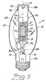
- Fig. 5 is an elevational view of an embodiment of the invention employed with an arc discharge lamp
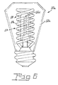
- Fig. 6 is an elevational view of an embodiment of the invention employed with a filamented lamp
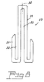
- Fig. 7 is plan view of an alternate configuration for a containment vessel
- Fig. 8 is a partial, elevational view of the containment vessel shown in Fig. 7;
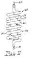
- Fig. 9 is an elevational view of yet another embodiment of the invention.
- Fig. 10 is a diagrammatic representation of the fractures resulting from a burst light source capsule.
- a prior art metal halide arc discharge lamp 100 including a lamp envelope 120 and an arc tube 140 mounted within the envelope by mounting frame 160.
- the arc tube is positioned within a shroud 200 which can also be supported by the mounting frame 160.
- Electrical energy is coupled to the arc tube 140 through a base 220, a lamp stem 240 and electrical leads 260 and 280.
- the arc tube contains a chemical fill or dose of materials to provide light when an arc is initiated therein, as is known.
- the shroud 200 comprises a cylindrical tube of light transmissive, heat resistant material such as quartz.
- a wire mounting frame 160 supports both the arc tube 140 and the shroud 200 within the lamp envelope 120.
- the mounting frame 160 includes a metal support rod 300 attached to lamp stem 240 by a strap 310.
- the support rod 300 engages an inward projection 320 in the upper end of the lamp envelope 120.
- the support rod 300 in its central portion is parallel to a central axis of the arc tube 140 and shroud 200.
- the mounting means 160 further includes an upper clip 400 and a lower clip 420, which secure both arc tube 140 and shroud 200 to support rod 300.
- the clips 400 and 420 are attached to the support rod 300, preferably by welding.
- a lamp 10 having an envelope 12 with a longitudinal axis 14 and with a light source capsule 16 contained therein.
- the light source capsule 16 can be an arc discharge tube 16b, such as for a metal halide lamp, or a filamented lamp capsule 16c (see Fig. 6) that operates at a pressure greater than or less than the pressure of a surrounding gas and is therefore capable of shattering into shards with a given kinetic energy able to fracture the envelope 12.
- the lamp 10 contains a containment vessel 18 that is spaced from and surrounds the light source capsule 16.
- the containment vessel 18 comprises a transparent structure 19 that is formed to provide multiple, independent, localized fractures capable of absorbing the given kinetic energy possessed by the shards in the event of a capsule burst.
- the light source capsule 16 can be mounted within the containment vessel 18 by any suitable means.
- the transparent structure 19 is selected from glass or ceramic and has alternating solid areas 20 and spaces 22.
- the containment vessel 18 is a helix 18a having a helix longitudinal axis 24 substantially coaxial with the envelope longitudinal axis 14.
- the helix 18a (see Fig. 4) is preferably constructed of glass tubing 26, such as an aluminosilicate glass, and the spaces 22 are formed between turns of the helix 18a.
- Suitable glasses for construction of the helix are Type 1724 from Corning Glass Company, Schott Glass 8252, from Schott Glass Company and GE Type 180, from General Electric Company.
- the helix can be a single helix as shown in Fig. 2 or a bifilar helix as shown in Figs. 5 and 6, with the bifilar helix being preferred.
- the glass tubing 26 can remain empty, as shown in Fig. 4 or it can have a wire, 32 threaded therethrough, as shown in Fig. 3. It is not necessary that the wire have an external diameter matching that of the internal diameter of the tubing and, preferably, the external diameter of the wire is as small as practicable to reduce unwanted shadowing effects.
- the tubing 26 can contain a gas, such as neon or argon, which may further help in absorbing the kinetic energy from a capsule burst.
- a gas such as neon or argon
- the tubing can be provided with electrodes 28, 30, to form a second light source 16a, which second light source can provide a light output different from that emitted by the first light source capsule 16. See, for example, Fig. 9.
- the tubing is preferred for its reduced weight.
- the tubing when used as a containment vessel in a 400 watt metal halide lamp, the tubing has an ID of 3mm and an OD of 5mm.
- the outer diameter of the helix was about 43mm and the overall length was about 7 cm.
- the wire When a wire was employed, the wire was nickel and was .015 inches in diameter and approximately 1.1 meter in length. The actual dimensions will vary in accordance with the size of the light source capsule being protected.
- the spacing of the coils in the helix is important and preferably is equal to or less than the diameter of the tubing. If the spacing is too large it is possible for large shards having sufficient kinetic energy to escape the containment vessel and fracture the outer envelope. On the lower level, the spacing should be nonzero; i.e., there must be some space between the coils to prevent a crack from propagating laterally across turns of the tubing. That is, when the tubing has a diameter D, the spacing between turns is D1, where D1 is equal to or less than D but greater than zero, as is shown in Fig. 2.
- an alternative transparent structure 19 of solid areas 20 and spaces 22 can be realized via a multiplicity of U-shaped channels aligned parallel to the longitudinal axis 14 of the lamp 10.
- a lamp 10 comprises an envelope 12 having a base end 12a, a middle portion 12b and domed end 12c arrayed along the envelope longitudinal axis 14.
- Two spaced apart electrical lead-ins 34, 36, are sealed in the base end 12a and extend into the envelope 12.
- a substantially U-shaped frame 38 is positioned within envelope 12, the U-shaped frame being comprised of glass tubing 26a.
- the light source capsule 16 in this instance comprises an arc discharge capsule 16b positioned within the frame 38 and the containment vessel 18 and, as noted, can be supported in any suitable manner.
- the containment vessel 18 is spaced from and surrounds the arc discharge capsule 16b.
- the containment vessel 18 preferably is integrally formed with the frame 38.
- the frame 38 can be positioned within the envelope 12 by fitting the ends 38a, 38b over the electrical lead-ins 34, 36.
- the opposite end 38c of the frame 38 is received in the domed end 12c of the envelope 12.
- the end 38c of the frame 38 can be provided with a spring section 38d to allow for tolerance variations in the envelope dimensions.
- the frame end 38c can be made smaller than the internal dimension of the domed end 12c and be provided with snubbers, as known in the art.
- the use of the transparent glass frame 38 eliminates the shadowing effect present in lamps that use wire frames. Also, the use of the electrically isolating glass frame eliminates the sodium loss occasioned by the photoelectric effect when wire frames are used.
- Fig. 6 is shown a lamp 10a having an envelope 12a and a light source capsule 16c such as a tungsten halogen capsule.
- Light source capsule 16c operates also at pressures above the pressure of the surrounding environment.
- these lamps employed a relatively heavy outer envelope to contain shards in the event of a capsule burst; however, as shown in Fig. 6, the light source capsule 16c can be protected by a containment vessel 18 allowing the lamp to use a diminished thickness glass envelope, thus reducing weight and cost.
- a containment vessel for lamps using light source capsules that operate at greater than (or substantially less than) the pressure of the surrounding gas.
- the containment vessel is lightweight and eliminates the shadowing effect caused by wire frames. It is more effective than prior art quartz tubular shrouds because it absorbs more energy from impinging glass shards, thereby enhancing the breakup of the shards themselves, reducing their size and velocity. This reduces the energy and momentum with which the residual shattered glass of the light source capsule strikes the inside surface of the outer envelope.
Landscapes
- Vessels And Coating Films For Discharge Lamps (AREA)
- Eye Examination Apparatus (AREA)
- Color Printing (AREA)
- Air Bags (AREA)
- Discharge Lamp (AREA)
- Non-Portable Lighting Devices Or Systems Thereof (AREA)
Abstract
Description
- TECHNICAL FIELD
- This invention relates to lamps and more particularly to such lamps having a light source capsule that operates at an internal pressure greater than or less than the pressure of a gas surrounding the capsule. Such lamps include tungsten halogen lamps and arc discharge lamps, such as metal halide arc discharge lamps.
- BACKGROUND ART
- Lamps such as those described above usually have a light source capsule that is enclosed in an outer envelope that can be evacuated or contain an inert gas. The light source capsule can be subject to bursting if its internal pressure is greater than or less than the pressure of the gas surrounding the capsule. A burst of a light source capsule can shatter the outer envelope and thereby create a dangerous situation. To provide a measure of protection from such bursts it has been the industry practice to enclose the lamp in a protective fixture or to provide an unusually robust outer envelope to contain any shards from the burst capsule.
- In particular, metal halide arc discharge lamps are frequently employed in commercial usage because of their high luminous efficacy and long life. A typical metal halide arc discharge lamp includes a quartz or fused silica arc tube that is hermetically sealed within a borosilicate glass outer envelope. The arc tube, itself hermetically sealed, has tungsten electrodes sealed into opposite ends and contains a fill material that can include mercury, as well as metal halide additives, and a rare gas to facilitate starting. In some cases, particularly in high wattage lamps, the outer envelope is filled with nitrogen or another inert gas at less than atmospheric pressure. In other cases, particularly in low wattage lamps, the outer envelope is evacuated.
- It has been found desirable to provide such lamps, and in particular, metal halide arc discharge lamps with a shroud that comprises a generally light-transmissive member, such as quartz, that is able to withstand high operating temperatures. The arc tube and the shroud are coaxially mounted within the lamp envelope with the arc tube located within the shroud. Preferably, the shroud is tubular and open at both ends. In other cases, the shroud is open on one end and has a domed configuration on the other end. Shrouds for metal halide arc discharge lamps are disclosed in
U.S. patent no. 4,499,396 issued February 12, 1985 to Fohl et al. andU.S. patent no. 4,580,989 issued April 8, 1986 to Fohl et al. See alsoU.S. patent no. 4,281,274 issued July 28, 1981 to Bechard et al. - The shroud has several beneficial effects on lamp operation. In lamps with a gas-filled outer envelope, the shroud reduces convective heat losses from the arc tube and thereby improves the luminous output and the color temperature of the lamp. In lamps with an evacuated outer envelope, the shroud helps to elevate and/or equalize the surface temperature of the arc tube. In addition, the shroud effectively reduces sodium losses and improves the maintenance of phosphor efficiency in metal halide lamps having a phosphor coating on the inside surface of the outer envelope. Finally, the shroud improves the safety of the lamp by acting as a containment device in the event that the arc tube shatters.
- While these shrouded lamps have received great acceptance in the marketplace, (since lamps so equipped do not require an extensive, enclosed fixture) the use of the quartz shroud adds considerable expense, and considerable weight, to the lamp. Additionally, these lamps employ a wire frame to mount the arc tube and the shroud, and this wire frame can contribute to a loss of sodium from the arc tube, which loss affects the color output of the lamp as well as the life of the lamp and, additionally, contributes an undesired shadow.
- Further, the quartz shroud is a single piece that favors a single (or very limited number) continuous 'global' fracture when struck by an arc tube shard because of its nearly uniform rigid continuum structure and the fact that crack propagation velocity in quartz tubing is in the neighborhood of ~ 2000 m/sec. This velocity is much greater than the nominal shard/envelope impact velocity of about 25 m/sec. Therefore, an initiating crack spreads elsewhere around the shroud before other shards have a chance for their own impacts. This behavior can weaken the tubular shroud at locations other than the initial impact site and can yield relatively large fragmented pieces of shroud and/or light source capsule. Subsequent shard impacts at these other locations are met with significantly reduced barrier strength. The shards are propelled toward the inner surface of the outer envelope by expanding gases from the light source capsule burst. Therefore, it is possible under some conditions for the shroud to contribute to the fracture of the outer envelope, the very situation it was supposed to prevent.
- DISCLOSURE OF INVENTION
- It is, therefore, an object of the invention to obviate the disadvantages of the prior art.
- It is another object of the invention to enhance the operation of metal halide arc discharge lamps.
- Yet another object of the invention is elimination of unwanted shadow effects from the lamp.
- Yet another object of the invention is the provision of a structure that prevents large shards from engaging an outer envelope.
- Still another object of the invention is the provision of an integral frame and containment structure for lamps employing a light source capsule that, at least during operation, contains an atmosphere at a pressure different from the pressure of the gas surrounding it.
- These objects are accomplished, in one aspect of the invention, by a lamp having an envelope with a longitudinal axis and with a light source capsule contained therein, said light source capsule being capable of shattering into shards with a given kinetic energy able to fracture said envelope, the improvement comprising: a containment vessel spaced from and surrounding said light source capsule, said containment vessel comprising a transparent structure formed to provide multiple, independent, localized fractures capable of absorbing said given kinetic energy.
- This containment vessel itself will not generate large shards and effectively reduces the kinetic energy of the shards to protect the outer envelope and contain all of the shards.
- BRIEF DESCRIPTION OF THE DRAWINGS
- Fig. 1 is a perspective view of an exemplary prior art type of protected high intensity discharge lamp;
- Fig. 2 is an elevational view of an embodiment of the invention;
- Fig. 3 is a partial, elevational sectional view of one form of structure that can be employed with the invention;
- Fig. 4 is a partial, elevational sectional view of a second form of structure that can be employed with the invention;
- Fig. 5 is an elevational view of an embodiment of the invention employed with an arc discharge lamp;
- Fig. 6 is an elevational view of an embodiment of the invention employed with a filamented lamp;
- Fig. 7 is plan view of an alternate configuration for a containment vessel;
- Fig. 8 is a partial, elevational view of the containment vessel shown in Fig. 7;
- Fig. 9 is an elevational view of yet another embodiment of the invention; and
- Fig. 10 is a diagrammatic representation of the fractures resulting from a burst light source capsule.
- MODE FOR CARRYING OUT THE INVENTION
- For a better understanding of the present invention, together with other and further objects, advantages and capabilities thereof, reference is made to the following disclosure and appended claims taken in conjunction with the above-described drawings.
- Referring now to the drawings with greater particularity, there is shown in Fig. 1 a prior art metal halide
arc discharge lamp 100 including alamp envelope 120 and anarc tube 140 mounted within the envelope by mountingframe 160. The arc tube is positioned within ashroud 200 which can also be supported by themounting frame 160. Electrical energy is coupled to thearc tube 140 through abase 220, alamp stem 240 andelectrical leads shroud 200 comprises a cylindrical tube of light transmissive, heat resistant material such as quartz. - A
wire mounting frame 160 supports both thearc tube 140 and theshroud 200 within thelamp envelope 120. Themounting frame 160 includes ametal support rod 300 attached tolamp stem 240 by a strap 310. Thesupport rod 300 engages aninward projection 320 in the upper end of thelamp envelope 120. Thesupport rod 300 in its central portion is parallel to a central axis of thearc tube 140 andshroud 200. The mounting means 160 further includes anupper clip 400 and alower clip 420, which secure botharc tube 140 andshroud 200 to supportrod 300. Theclips support rod 300, preferably by welding. - Referring now to Fig. 5, there is shown a
lamp 10 having anenvelope 12 with alongitudinal axis 14 and with alight source capsule 16 contained therein. Thelight source capsule 16 can be anarc discharge tube 16b, such as for a metal halide lamp, or afilamented lamp capsule 16c (see Fig. 6) that operates at a pressure greater than or less than the pressure of a surrounding gas and is therefore capable of shattering into shards with a given kinetic energy able to fracture theenvelope 12. Thelamp 10 contains acontainment vessel 18 that is spaced from and surrounds thelight source capsule 16. Thecontainment vessel 18 comprises atransparent structure 19 that is formed to provide multiple, independent, localized fractures capable of absorbing the given kinetic energy possessed by the shards in the event of a capsule burst. Thelight source capsule 16 can be mounted within thecontainment vessel 18 by any suitable means. - The
transparent structure 19 is selected from glass or ceramic and has alternatingsolid areas 20 andspaces 22. In a preferred embodiment thecontainment vessel 18 is ahelix 18a having a helixlongitudinal axis 24 substantially coaxial with the envelopelongitudinal axis 14. - The
helix 18a (see Fig. 4) is preferably constructed ofglass tubing 26, such as an aluminosilicate glass, and thespaces 22 are formed between turns of thehelix 18a. Suitable glasses for construction of the helix are Type 1724 from Corning Glass Company, Schott Glass 8252, from Schott Glass Company and GE Type 180, from General Electric Company. - The helix can be a single helix as shown in Fig. 2 or a bifilar helix as shown in Figs. 5 and 6, with the bifilar helix being preferred.
- The
glass tubing 26 can remain empty, as shown in Fig. 4 or it can have a wire, 32 threaded therethrough, as shown in Fig. 3. It is not necessary that the wire have an external diameter matching that of the internal diameter of the tubing and, preferably, the external diameter of the wire is as small as practicable to reduce unwanted shadowing effects. - Alternatively, the
tubing 26 can contain a gas, such as neon or argon, which may further help in absorbing the kinetic energy from a capsule burst. Also, when containing a gas that is capable of illumination, the tubing can be provided withelectrodes light source capsule 16. See, for example, Fig. 9. - While the
transparent structure 19 can be solid rod, as shown in Fig. 5, the tubing is preferred for its reduced weight. In a preferred embodiment of the invention, when used as a containment vessel in a 400 watt metal halide lamp, the tubing has an ID of 3mm and an OD of 5mm. The outer diameter of the helix was about 43mm and the overall length was about 7 cm. When a wire was employed, the wire was nickel and was .015 inches in diameter and approximately 1.1 meter in length. The actual dimensions will vary in accordance with the size of the light source capsule being protected. - The spacing of the coils in the helix is important and preferably is equal to or less than the diameter of the tubing. If the spacing is too large it is possible for large shards having sufficient kinetic energy to escape the containment vessel and fracture the outer envelope. On the lower level, the spacing should be nonzero; i.e., there must be some space between the coils to prevent a crack from propagating laterally across turns of the tubing. That is, when the tubing has a diameter D, the spacing between turns is D1, where D1 is equal to or less than D but greater than zero, as is shown in Fig. 2. While the spacing is shown as being consistent, it is possible for the spacing to be varied so long as it remains nonzero at the lower range and at the upper range is not large enough to permit heavy shards from exiting through the spaces. This ensures that the fractures remain small and localized at or very near their impact sites. Thus, the fractures are effectively distributed according to the random directions along which the shards travel. Each fracture independently absorbs energy from its corresponding shard impact. The total energy absorbed is greater than it would be if the containment vessel were a rigid continuum. Additionally, the spacing between the turns of the coils allows the pressurized gas within the capsule to escape laterally, a condition not possible with the solid wall tubular shroud. A diagrammatic representation of a burst and the independent fractures resulting is shown in Fig. 10
- Referring now to Figs. 7 and 8 an alternative
transparent structure 19 ofsolid areas 20 andspaces 22 can be realized via a multiplicity of U-shaped channels aligned parallel to thelongitudinal axis 14 of thelamp 10. - Referring again to Fig. 5, it will be seen that a
lamp 10 comprises anenvelope 12 having abase end 12a, a middle portion 12b anddomed end 12c arrayed along the envelopelongitudinal axis 14. Two spaced apart electrical lead-ins 34, 36, are sealed in thebase end 12a and extend into theenvelope 12. A substantiallyU-shaped frame 38 is positioned withinenvelope 12, the U-shaped frame being comprised ofglass tubing 26a. Thelight source capsule 16 in this instance comprises anarc discharge capsule 16b positioned within theframe 38 and thecontainment vessel 18 and, as noted, can be supported in any suitable manner. Thecontainment vessel 18 is spaced from and surrounds thearc discharge capsule 16b. Thecontainment vessel 18 preferably is integrally formed with theframe 38. - The
frame 38 can be positioned within theenvelope 12 by fitting the ends 38a, 38b over the electrical lead-ins 34, 36. Theopposite end 38c of theframe 38 is received in thedomed end 12c of theenvelope 12. To insure a friction fit within thedomed end 12c, theend 38c of theframe 38 can be provided with aspring section 38d to allow for tolerance variations in the envelope dimensions. Alternatively, theframe end 38c can be made smaller than the internal dimension of thedomed end 12c and be provided with snubbers, as known in the art. - The use of the
transparent glass frame 38 eliminates the shadowing effect present in lamps that use wire frames. Also, the use of the electrically isolating glass frame eliminates the sodium loss occasioned by the photoelectric effect when wire frames are used. - The invention is useful also with other types of lamps employing light source capsules. In Fig. 6 is shown a
lamp 10a having anenvelope 12a and alight source capsule 16c such as a tungsten halogen capsule.Light source capsule 16c operates also at pressures above the pressure of the surrounding environment. In the past, these lamps employed a relatively heavy outer envelope to contain shards in the event of a capsule burst; however, as shown in Fig. 6, thelight source capsule 16c can be protected by acontainment vessel 18 allowing the lamp to use a diminished thickness glass envelope, thus reducing weight and cost. - Thus there is provided a containment vessel for lamps using light source capsules that operate at greater than (or substantially less than) the pressure of the surrounding gas. The containment vessel is lightweight and eliminates the shadowing effect caused by wire frames. It is more effective than prior art quartz tubular shrouds because it absorbs more energy from impinging glass shards, thereby enhancing the breakup of the shards themselves, reducing their size and velocity. This reduces the energy and momentum with which the residual shattered glass of the light source capsule strikes the inside surface of the outer envelope.
- While there have been shown and described what are at present considered to be the preferred embodiments of the invention, it will be apparent to those skilled in the art that various changes and modifications can be made herein without departing from the scope of the invention as defined by the appended claims.
Claims (15)
- In a lamp having an envelope with a longitudinal axis and with a light source capsule contained therein, said light source capsule being capable of shattering into shards with a given kinetic energy able to fracture said envelope, the improvement comprising:a containment vessel spaced from and surrounding said light source capsule, said containment vessel comprising a transparent structure formed to provide multiple, independent, localized fractures capable of absorbing said given kinetic energy possessed by said shards.
- The lamp of claim 1 wherein said transparent structure is selected from glass or ceramic and having alternating solid areas and spaces.
- The lamp of Claim 2 wherein said containment vessel is a helix having a helix longitudinal axis substantially coaxial with said envelope longitudinal axis.
- The lamp of Claim 3 wherein said helix is constructed of tubing and said spaces are formed between turns of said helix.
- The lamp of Claim 4 wherein said tubing is gas-filled.
- The lamp of Claim 5 wherein said gas is selected from the group of argon and neon.
- The lamp of Claim 6 wherein said tubing is sealed and contains an electrode at each end to form a second light source within said outer envelope.
- The lamp of Claim 3 wherein said helix is constructed of solid rod.
- The lamp of Claim 4 wherein said tubing contains a refractory wire threaded therethrough.
- The lamp of Claim 4 wherein said tubing has a given diameter D and said spaces have a dimension D1 equal to or less than said given diameter D when measured along said helix longitudinal axis.
- The lamp of Claim 2 wherein said solid areas and said spaces extend parallel to said envelope longitudinal axis.
- The lamp of Claim 7 wherein said light source capsule emits light of a first color and said second light source emits light of a different color.
- A high intensity discharge lamp comprising an envelope having a base end, a middle portion and domed end arrayed along an envelope longitudinal axis;
two spaced apart electrical lead-ins sealed in said base end and extending into said envelope;
a substantially U-shaped frame within said envelope, said U-shaped frame comprised of glass tubing;
a light source capsule comprising an arc discharge capsule positioned within said frame; and
a containment vessel spaced from and surrounding said light source capsule, said containment vessel comprising a transparent structure formed to provide multiple, independent, localized fractures capable of absorbing said given kinetic energy possessed by said shards and being attached to said frame. - A lamp comprising:an outer envelope of light transmissive material arrayed about an envelope longitudinal axis;a light source capsule contained within said outer envelope anda containment vessel spaced from and surrounding said light source capsule, said containment vessel comprising a transparent structure selected from glass or ceramic and having alternating solid areas and spaces.
- The lamp of Claim 28 wherein said helix is bifilar.
Applications Claiming Priority (1)
| Application Number | Priority Date | Filing Date | Title |
|---|---|---|---|
| US11/301,504 US7417363B2 (en) | 2005-12-13 | 2005-12-13 | Containment vessel for light source capsules operating at other than the pressure of a surrounding gas |
Publications (3)
| Publication Number | Publication Date |
|---|---|
| EP1798755A2 true EP1798755A2 (en) | 2007-06-20 |
| EP1798755A3 EP1798755A3 (en) | 2007-08-22 |
| EP1798755B1 EP1798755B1 (en) | 2010-02-17 |
Family
ID=37834217
Family Applications (1)
| Application Number | Title | Priority Date | Filing Date |
|---|---|---|---|
| EP06125245A Not-in-force EP1798755B1 (en) | 2005-12-13 | 2006-12-01 | Containment structure for light source capsules operating at other than the pressure of a surrounding gas |
Country Status (7)
| Country | Link |
|---|---|
| US (1) | US7417363B2 (en) |
| EP (1) | EP1798755B1 (en) |
| JP (1) | JP2007165314A (en) |
| CN (1) | CN101082410A (en) |
| AT (1) | ATE458266T1 (en) |
| CA (1) | CA2557123A1 (en) |
| DE (1) | DE602006012269D1 (en) |
Cited By (1)
| Publication number | Priority date | Publication date | Assignee | Title |
|---|---|---|---|---|
| WO2022013381A3 (en) * | 2020-07-15 | 2022-03-10 | biowaterworld europe GmbH | Device for generating electromagnetic radiation and system comprising a device of this type |
Families Citing this family (2)
| Publication number | Priority date | Publication date | Assignee | Title |
|---|---|---|---|---|
| JP2011070869A (en) * | 2009-09-25 | 2011-04-07 | Iwasaki Electric Co Ltd | Ceramic metal halide lamp |
| US10292237B2 (en) | 2016-06-30 | 2019-05-14 | Yehi Or Light Creation Limited | High efficiency light system |
Citations (4)
| Publication number | Priority date | Publication date | Assignee | Title |
|---|---|---|---|---|
| US4888517A (en) | 1987-08-28 | 1989-12-19 | Gte Products Corporation | Double-enveloped lamp having a shield surrounding a light-source capsule within a thick-walled outer envelope |
| US4950938A (en) | 1988-11-16 | 1990-08-21 | North American Philips Corp. | Discharge lamp with discharge vessel rupture shield |
| JP2000164174A (en) | 1998-11-24 | 2000-06-16 | Matsushita Electronics Industry Corp | Low-pressure mercury vapor discharge lamp |
| US6400104B1 (en) | 2000-09-12 | 2002-06-04 | Byung Il Ham | Fluorescent lamp assembly with nightlight |
Family Cites Families (16)
| Publication number | Priority date | Publication date | Assignee | Title |
|---|---|---|---|---|
| GB489925A (en) * | 1937-05-21 | 1938-08-05 | British Thomson Houston Co Ltd | Improvements in and relating to electric discharge lamps |
| US3764844A (en) * | 1972-04-28 | 1973-10-09 | A Schmidt | Gas discharge lamp and method for making same |
| US4178534A (en) * | 1978-07-07 | 1979-12-11 | Gte Laboratories Incorporated | Methods of and apparatus for electrodeless discharge excitation |
| JPS55144646A (en) * | 1979-04-30 | 1980-11-11 | Matsushita Electric Works Ltd | Small fluorescent lamp of high intensity |
| NL8600049A (en) * | 1986-01-13 | 1987-08-03 | Philips Nv | LOW-PRESSURE MERCURY DISCHARGE LAMP. |
| US4801846A (en) * | 1986-12-19 | 1989-01-31 | Gte Laboratories Incorporated | Rare earth halide light source with enhanced red emission |
| US4942330A (en) * | 1988-09-30 | 1990-07-17 | Gte Products Corporation | Lamp assembly utilizing shield and ceramic fiber mesh for containment |
| JPH03147247A (en) * | 1989-10-19 | 1991-06-24 | Gte Prod Corp | Lamp assembly body using shielding body for containment and ceramic fiber mesh |
| EP0447957A3 (en) * | 1990-03-19 | 1992-04-29 | Walter Holzer | Compact fluorescent lamp |
| US5729078A (en) * | 1991-12-23 | 1998-03-17 | U.S. Philips Corporation | Electric lamp with containment sleeve having a helically coiled metal wire |
| JP3209826B2 (en) * | 1993-05-18 | 2001-09-17 | 松下電器産業株式会社 | Variable color light source device |
| JP3412484B2 (en) * | 1997-10-31 | 2003-06-03 | 松下電器産業株式会社 | Metal halide lamp |
| US6064155A (en) * | 1998-05-04 | 2000-05-16 | Matsushita Electric Works Research And Development Labratory Inc | Compact fluorescent lamp as a retrofit for an incandescent lamp |
| US6153968A (en) * | 1998-10-02 | 2000-11-28 | Philips Electronics North America Corp. | Metal halide lamp with stem mounted support frame for arc tube shield |
| US6995513B2 (en) * | 2001-05-08 | 2006-02-07 | Koninklijke Philips Electronics N.V. | Coil antenna/protection for ceramic metal halide lamps |
| US7053555B2 (en) * | 2002-11-21 | 2006-05-30 | Matsushita Electric Industrial Co., Ltd. | Arc tube, discharge lamp, and production method of such arc tube, which enables brighter illuminance |
-
2005
- 2005-12-13 US US11/301,504 patent/US7417363B2/en not_active Expired - Fee Related
-
2006
- 2006-08-24 CA CA002557123A patent/CA2557123A1/en not_active Abandoned
- 2006-12-01 DE DE602006012269T patent/DE602006012269D1/en active Active
- 2006-12-01 AT AT06125245T patent/ATE458266T1/en not_active IP Right Cessation
- 2006-12-01 EP EP06125245A patent/EP1798755B1/en not_active Not-in-force
- 2006-12-12 JP JP2006334335A patent/JP2007165314A/en active Pending
- 2006-12-13 CN CNA2006101310231A patent/CN101082410A/en active Pending
Patent Citations (4)
| Publication number | Priority date | Publication date | Assignee | Title |
|---|---|---|---|---|
| US4888517A (en) | 1987-08-28 | 1989-12-19 | Gte Products Corporation | Double-enveloped lamp having a shield surrounding a light-source capsule within a thick-walled outer envelope |
| US4950938A (en) | 1988-11-16 | 1990-08-21 | North American Philips Corp. | Discharge lamp with discharge vessel rupture shield |
| JP2000164174A (en) | 1998-11-24 | 2000-06-16 | Matsushita Electronics Industry Corp | Low-pressure mercury vapor discharge lamp |
| US6400104B1 (en) | 2000-09-12 | 2002-06-04 | Byung Il Ham | Fluorescent lamp assembly with nightlight |
Cited By (1)
| Publication number | Priority date | Publication date | Assignee | Title |
|---|---|---|---|---|
| WO2022013381A3 (en) * | 2020-07-15 | 2022-03-10 | biowaterworld europe GmbH | Device for generating electromagnetic radiation and system comprising a device of this type |
Also Published As
| Publication number | Publication date |
|---|---|
| CA2557123A1 (en) | 2007-06-13 |
| EP1798755A3 (en) | 2007-08-22 |
| ATE458266T1 (en) | 2010-03-15 |
| US20070132397A1 (en) | 2007-06-14 |
| DE602006012269D1 (en) | 2010-04-01 |
| CN101082410A (en) | 2007-12-05 |
| US7417363B2 (en) | 2008-08-26 |
| EP1798755B1 (en) | 2010-02-17 |
| JP2007165314A (en) | 2007-06-28 |
Similar Documents
| Publication | Publication Date | Title |
|---|---|---|
| US8823264B2 (en) | Light source | |
| EP3295471A2 (en) | Laser driven sealed beam lamp with improved stability | |
| EP1798755B1 (en) | Containment structure for light source capsules operating at other than the pressure of a surrounding gas | |
| US20060049733A1 (en) | Protected Metal Halide Lamp | |
| US5754000A (en) | Apparatus for providing radiation | |
| EP0104594B1 (en) | Double-enveloped lamp | |
| US6930443B2 (en) | Arc tube/shroud holder for hid lamp | |
| US7511406B2 (en) | Metal halide arc discharge lamp | |
| EP0381279A1 (en) | High-pressure gas discharge lamp | |
| US6737791B2 (en) | Snap-on spring clip for ceramic hid lamp | |
| US7135811B2 (en) | Shroud holder for quartz and ceramic arc tubes | |
| JPH06295708A (en) | Metal halide arc lamp with shroud for containment made of glass | |
| JP4791897B2 (en) | Ceramic metal halide lamp and lighting device | |
| WO2007122522A2 (en) | Discharge lamp with protective shroud | |
| US7701142B2 (en) | Ceramic HID arc tube assembly | |
| EP1658633B1 (en) | High-pressure discharge lamp | |
| JPH11312494A (en) | Small high color rendering metal halide lamp | |
| JPH09204903A (en) | Metal halide lamp | |
| JP3976051B2 (en) | High pressure discharge lamp | |
| US20030127978A1 (en) | Multi-position hid lamp with single getter | |
| JPH07142033A (en) | Metal halide lamp | |
| GB2295721A (en) | Discharge lamps |
Legal Events
| Date | Code | Title | Description |
|---|---|---|---|
| PUAI | Public reference made under article 153(3) epc to a published international application that has entered the european phase |
Free format text: ORIGINAL CODE: 0009012 |
|
| AK | Designated contracting states |
Kind code of ref document: A2 Designated state(s): AT BE BG CH CY CZ DE DK EE ES FI FR GB GR HU IE IS IT LI LT LU LV MC NL PL PT RO SE SI SK TR |
|
| AX | Request for extension of the european patent |
Extension state: AL BA HR MK YU |
|
| PUAL | Search report despatched |
Free format text: ORIGINAL CODE: 0009013 |
|
| AK | Designated contracting states |
Kind code of ref document: A3 Designated state(s): AT BE BG CH CY CZ DE DK EE ES FI FR GB GR HU IE IS IT LI LT LU LV MC NL PL PT RO SE SI SK TR |
|
| AX | Request for extension of the european patent |
Extension state: AL BA HR MK YU |
|
| RIN1 | Information on inventor provided before grant (corrected) |
Inventor name: KOENIGSBERG, WILLIAM Inventor name: WENTZEL, DAVID Inventor name: LAPATOVICH, WALTER Inventor name: SELVERIAN, JOHN Inventor name: JOHNSTON, DAVID |
|
| 17P | Request for examination filed |
Effective date: 20070910 |
|
| 17Q | First examination report despatched |
Effective date: 20071011 |
|
| AKX | Designation fees paid |
Designated state(s): AT BE BG CH CY CZ DE DK EE ES FI FR GB GR HU IE IS IT LI LT LU LV MC NL PL PT RO SE SI SK TR |
|
| GRAP | Despatch of communication of intention to grant a patent |
Free format text: ORIGINAL CODE: EPIDOSNIGR1 |
|
| GRAJ | Information related to disapproval of communication of intention to grant by the applicant or resumption of examination proceedings by the epo deleted |
Free format text: ORIGINAL CODE: EPIDOSDIGR1 |
|
| GRAP | Despatch of communication of intention to grant a patent |
Free format text: ORIGINAL CODE: EPIDOSNIGR1 |
|
| GRAS | Grant fee paid |
Free format text: ORIGINAL CODE: EPIDOSNIGR3 |
|
| GRAA | (expected) grant |
Free format text: ORIGINAL CODE: 0009210 |
|
| AK | Designated contracting states |
Kind code of ref document: B1 Designated state(s): AT BE BG CH CY CZ DE DK EE ES FI FR GB GR HU IE IS IT LI LT LU LV MC NL PL PT RO SE SI SK TR |
|
| REG | Reference to a national code |
Ref country code: GB Ref legal event code: FG4D |
|
| REG | Reference to a national code |
Ref country code: CH Ref legal event code: EP |
|
| REG | Reference to a national code |
Ref country code: IE Ref legal event code: FG4D |
|
| REF | Corresponds to: |
Ref document number: 602006012269 Country of ref document: DE Date of ref document: 20100401 Kind code of ref document: P |
|
| REG | Reference to a national code |
Ref country code: NL Ref legal event code: VDEP Effective date: 20100217 |
|
| LTIE | Lt: invalidation of european patent or patent extension |
Effective date: 20100217 |
|
| PG25 | Lapsed in a contracting state [announced via postgrant information from national office to epo] |
Ref country code: ES Free format text: LAPSE BECAUSE OF FAILURE TO SUBMIT A TRANSLATION OF THE DESCRIPTION OR TO PAY THE FEE WITHIN THE PRESCRIBED TIME-LIMIT Effective date: 20100528 Ref country code: PT Free format text: LAPSE BECAUSE OF FAILURE TO SUBMIT A TRANSLATION OF THE DESCRIPTION OR TO PAY THE FEE WITHIN THE PRESCRIBED TIME-LIMIT Effective date: 20100617 Ref country code: LT Free format text: LAPSE BECAUSE OF FAILURE TO SUBMIT A TRANSLATION OF THE DESCRIPTION OR TO PAY THE FEE WITHIN THE PRESCRIBED TIME-LIMIT Effective date: 20100217 Ref country code: IS Free format text: LAPSE BECAUSE OF FAILURE TO SUBMIT A TRANSLATION OF THE DESCRIPTION OR TO PAY THE FEE WITHIN THE PRESCRIBED TIME-LIMIT Effective date: 20100617 |
|
| PG25 | Lapsed in a contracting state [announced via postgrant information from national office to epo] |
Ref country code: AT Free format text: LAPSE BECAUSE OF FAILURE TO SUBMIT A TRANSLATION OF THE DESCRIPTION OR TO PAY THE FEE WITHIN THE PRESCRIBED TIME-LIMIT Effective date: 20100217 Ref country code: PL Free format text: LAPSE BECAUSE OF FAILURE TO SUBMIT A TRANSLATION OF THE DESCRIPTION OR TO PAY THE FEE WITHIN THE PRESCRIBED TIME-LIMIT Effective date: 20100217 Ref country code: LV Free format text: LAPSE BECAUSE OF FAILURE TO SUBMIT A TRANSLATION OF THE DESCRIPTION OR TO PAY THE FEE WITHIN THE PRESCRIBED TIME-LIMIT Effective date: 20100217 Ref country code: FI Free format text: LAPSE BECAUSE OF FAILURE TO SUBMIT A TRANSLATION OF THE DESCRIPTION OR TO PAY THE FEE WITHIN THE PRESCRIBED TIME-LIMIT Effective date: 20100217 Ref country code: SI Free format text: LAPSE BECAUSE OF FAILURE TO SUBMIT A TRANSLATION OF THE DESCRIPTION OR TO PAY THE FEE WITHIN THE PRESCRIBED TIME-LIMIT Effective date: 20100217 |
|
| PG25 | Lapsed in a contracting state [announced via postgrant information from national office to epo] |
Ref country code: NL Free format text: LAPSE BECAUSE OF FAILURE TO SUBMIT A TRANSLATION OF THE DESCRIPTION OR TO PAY THE FEE WITHIN THE PRESCRIBED TIME-LIMIT Effective date: 20100217 Ref country code: GR Free format text: LAPSE BECAUSE OF FAILURE TO SUBMIT A TRANSLATION OF THE DESCRIPTION OR TO PAY THE FEE WITHIN THE PRESCRIBED TIME-LIMIT Effective date: 20100518 Ref country code: EE Free format text: LAPSE BECAUSE OF FAILURE TO SUBMIT A TRANSLATION OF THE DESCRIPTION OR TO PAY THE FEE WITHIN THE PRESCRIBED TIME-LIMIT Effective date: 20100217 Ref country code: CY Free format text: LAPSE BECAUSE OF FAILURE TO SUBMIT A TRANSLATION OF THE DESCRIPTION OR TO PAY THE FEE WITHIN THE PRESCRIBED TIME-LIMIT Effective date: 20100217 Ref country code: BE Free format text: LAPSE BECAUSE OF FAILURE TO SUBMIT A TRANSLATION OF THE DESCRIPTION OR TO PAY THE FEE WITHIN THE PRESCRIBED TIME-LIMIT Effective date: 20100217 Ref country code: RO Free format text: LAPSE BECAUSE OF FAILURE TO SUBMIT A TRANSLATION OF THE DESCRIPTION OR TO PAY THE FEE WITHIN THE PRESCRIBED TIME-LIMIT Effective date: 20100217 Ref country code: SE Free format text: LAPSE BECAUSE OF FAILURE TO SUBMIT A TRANSLATION OF THE DESCRIPTION OR TO PAY THE FEE WITHIN THE PRESCRIBED TIME-LIMIT Effective date: 20100217 |
|
| PG25 | Lapsed in a contracting state [announced via postgrant information from national office to epo] |
Ref country code: BG Free format text: LAPSE BECAUSE OF FAILURE TO SUBMIT A TRANSLATION OF THE DESCRIPTION OR TO PAY THE FEE WITHIN THE PRESCRIBED TIME-LIMIT Effective date: 20100517 Ref country code: SK Free format text: LAPSE BECAUSE OF FAILURE TO SUBMIT A TRANSLATION OF THE DESCRIPTION OR TO PAY THE FEE WITHIN THE PRESCRIBED TIME-LIMIT Effective date: 20100217 Ref country code: CZ Free format text: LAPSE BECAUSE OF FAILURE TO SUBMIT A TRANSLATION OF THE DESCRIPTION OR TO PAY THE FEE WITHIN THE PRESCRIBED TIME-LIMIT Effective date: 20100217 |
|
| PLBE | No opposition filed within time limit |
Free format text: ORIGINAL CODE: 0009261 |
|
| STAA | Information on the status of an ep patent application or granted ep patent |
Free format text: STATUS: NO OPPOSITION FILED WITHIN TIME LIMIT |
|
| 26N | No opposition filed |
Effective date: 20101118 |
|
| PG25 | Lapsed in a contracting state [announced via postgrant information from national office to epo] |
Ref country code: DK Free format text: LAPSE BECAUSE OF FAILURE TO SUBMIT A TRANSLATION OF THE DESCRIPTION OR TO PAY THE FEE WITHIN THE PRESCRIBED TIME-LIMIT Effective date: 20100217 |
|
| PG25 | Lapsed in a contracting state [announced via postgrant information from national office to epo] |
Ref country code: IT Free format text: LAPSE BECAUSE OF FAILURE TO SUBMIT A TRANSLATION OF THE DESCRIPTION OR TO PAY THE FEE WITHIN THE PRESCRIBED TIME-LIMIT Effective date: 20100217 |
|
| PG25 | Lapsed in a contracting state [announced via postgrant information from national office to epo] |
Ref country code: MC Free format text: LAPSE BECAUSE OF NON-PAYMENT OF DUE FEES Effective date: 20101231 |
|
| REG | Reference to a national code |
Ref country code: CH Ref legal event code: PL |
|
| PG25 | Lapsed in a contracting state [announced via postgrant information from national office to epo] |
Ref country code: LI Free format text: LAPSE BECAUSE OF NON-PAYMENT OF DUE FEES Effective date: 20101231 Ref country code: CH Free format text: LAPSE BECAUSE OF NON-PAYMENT OF DUE FEES Effective date: 20101231 Ref country code: IE Free format text: LAPSE BECAUSE OF NON-PAYMENT OF DUE FEES Effective date: 20101201 |
|
| PG25 | Lapsed in a contracting state [announced via postgrant information from national office to epo] |
Ref country code: HU Free format text: LAPSE BECAUSE OF FAILURE TO SUBMIT A TRANSLATION OF THE DESCRIPTION OR TO PAY THE FEE WITHIN THE PRESCRIBED TIME-LIMIT Effective date: 20100818 Ref country code: LU Free format text: LAPSE BECAUSE OF NON-PAYMENT OF DUE FEES Effective date: 20101201 |
|
| PG25 | Lapsed in a contracting state [announced via postgrant information from national office to epo] |
Ref country code: TR Free format text: LAPSE BECAUSE OF FAILURE TO SUBMIT A TRANSLATION OF THE DESCRIPTION OR TO PAY THE FEE WITHIN THE PRESCRIBED TIME-LIMIT Effective date: 20100217 |
|
| PGFP | Annual fee paid to national office [announced via postgrant information from national office to epo] |
Ref country code: GB Payment date: 20121220 Year of fee payment: 7 |
|
| PGFP | Annual fee paid to national office [announced via postgrant information from national office to epo] |
Ref country code: DE Payment date: 20121220 Year of fee payment: 7 Ref country code: FR Payment date: 20130130 Year of fee payment: 7 |
|
| REG | Reference to a national code |
Ref country code: DE Ref legal event code: R119 Ref document number: 602006012269 Country of ref document: DE |
|
| GBPC | Gb: european patent ceased through non-payment of renewal fee |
Effective date: 20131201 |
|
| REG | Reference to a national code |
Ref country code: FR Ref legal event code: ST Effective date: 20140829 |
|
| REG | Reference to a national code |
Ref country code: DE Ref legal event code: R119 Ref document number: 602006012269 Country of ref document: DE Effective date: 20140701 |
|
| PG25 | Lapsed in a contracting state [announced via postgrant information from national office to epo] |
Ref country code: DE Free format text: LAPSE BECAUSE OF NON-PAYMENT OF DUE FEES Effective date: 20140701 |
|
| PG25 | Lapsed in a contracting state [announced via postgrant information from national office to epo] |
Ref country code: GB Free format text: LAPSE BECAUSE OF NON-PAYMENT OF DUE FEES Effective date: 20131201 Ref country code: FR Free format text: LAPSE BECAUSE OF NON-PAYMENT OF DUE FEES Effective date: 20131231 |