EP1798474A2 - Local cooling hole pattern - Google Patents
Local cooling hole pattern Download PDFInfo
- Publication number
- EP1798474A2 EP1798474A2 EP06256259A EP06256259A EP1798474A2 EP 1798474 A2 EP1798474 A2 EP 1798474A2 EP 06256259 A EP06256259 A EP 06256259A EP 06256259 A EP06256259 A EP 06256259A EP 1798474 A2 EP1798474 A2 EP 1798474A2
- Authority
- EP
- European Patent Office
- Prior art keywords
- cooling holes
- group
- assembly
- disposed
- recited
- Prior art date
- Legal status (The legal status is an assumption and is not a legal conclusion. Google has not performed a legal analysis and makes no representation as to the accuracy of the status listed.)
- Granted
Links
- 238000001816 cooling Methods 0.000 title claims abstract description 154
- 238000000034 method Methods 0.000 claims 5
- 238000002485 combustion reaction Methods 0.000 abstract description 7
- 238000010790 dilution Methods 0.000 description 23
- 239000012895 dilution Substances 0.000 description 23
- 150000001875 compounds Chemical class 0.000 description 6
- 238000010276 construction Methods 0.000 description 3
- 239000002826 coolant Substances 0.000 description 2
- 238000009826 distribution Methods 0.000 description 2
- 239000000446 fuel Substances 0.000 description 2
- 239000007789 gas Substances 0.000 description 2
- 239000000463 material Substances 0.000 description 2
- 230000003134 recirculating effect Effects 0.000 description 2
- 230000004308 accommodation Effects 0.000 description 1
- 230000000712 assembly Effects 0.000 description 1
- 238000000429 assembly Methods 0.000 description 1
- 230000015572 biosynthetic process Effects 0.000 description 1
- 239000000567 combustion gas Substances 0.000 description 1
- 230000000694 effects Effects 0.000 description 1
- 238000005755 formation reaction Methods 0.000 description 1
- 238000009413 insulation Methods 0.000 description 1
- 238000003754 machining Methods 0.000 description 1
- 238000012986 modification Methods 0.000 description 1
- 230000004048 modification Effects 0.000 description 1
- 230000003647 oxidation Effects 0.000 description 1
- 238000007254 oxidation reaction Methods 0.000 description 1
- 238000007789 sealing Methods 0.000 description 1
- 238000011144 upstream manufacturing Methods 0.000 description 1
Images


Classifications
-
- F—MECHANICAL ENGINEERING; LIGHTING; HEATING; WEAPONS; BLASTING
- F23—COMBUSTION APPARATUS; COMBUSTION PROCESSES
- F23R—GENERATING COMBUSTION PRODUCTS OF HIGH PRESSURE OR HIGH VELOCITY, e.g. GAS-TURBINE COMBUSTION CHAMBERS
- F23R3/00—Continuous combustion chambers using liquid or gaseous fuel
- F23R3/02—Continuous combustion chambers using liquid or gaseous fuel characterised by the air-flow or gas-flow configuration
- F23R3/04—Air inlet arrangements
- F23R3/06—Arrangement of apertures along the flame tube
Definitions
- This invention relates generally to a combustor liner for a gas turbine engine. More particularly, this invention is a cooling hole configuration for providing a desired cooling airflow proximate to cooling airflow disrupting features of a combustor liner.
- a combustor module for a gas turbine engine typically includes an outer casing and an inner liner.
- the liner and the casing are radially spaced apart to form a passage for compressed air.
- the liner forms a combustion chamber within which compressed air mixes with fuel and is ignited.
- the liner includes a hot side exposed to hot combustion gases and a cold side facing the passage formed between the liner and the casing.
- Liners can be single-wall or double-wall construction, single-piece construction or segmented construction in the form of discrete heat shields, panels or tiles.
- a plurality of cooling holes supply a thin layer of cooling air that insulates the hot side of the liner from extreme combustion temperatures.
- the liner also includes other openings much larger than the cooling holes that provide for the introduction of compressed air to feed the combustion process.
- the thin layer of cooling air can be disrupted by flow around the larger openings potentially resulting in elevated liner temperatures adjacent the larger openings.
- the liner includes other structural features such as seams and rails that disrupt cooling airflow causing elevated temperatures. Elevated or uneven temperature distributions within the liner can promote undesired oxidation of the liner material, coating-failure or thermally-induced stresses that degrade the effectiveness, integrity and life of the liner.
- cooling holes in a different grouping densities around larger openings or other features that may disrupt cooling airflow.
- the increased number of cooling holes around larger openings and other features increase airflow preferentially in these areas and are somewhat effective in maintaining the desired cooling airflow.
- the greater cooling airflow provided around such openings and other disrupting configurations utilizes a large portion of the limited quantity of cooling air provided to the combustor liner.
- the increased demand for cooling airflow in the localized areas around larger opening and disruptions reduces the overall cooling airflow that is available for the remaining portions of the liner assembly.
- the amount of cooling airflow is limited by the design of the combustor liner and increases in cooling airflow requirements can impact other design and performance requirements.
- An example combustor assembly according to this invention includes a plurality of cooling holes for providing film cooling of a combustor liner that are preferentially oriented relative to a flow-disrupting structure.
- a preferred combustor liner utilizes groups of cooling holes that are provided in a generally uniform density with changes to the circumferential angle of some cooling holes to accommodate specific structural features that create disruptions in cooling airflow.
- An example combustor liner assembly includes a first plurality of cooling holes within the combustor liner that are angled through the liner at a first compound angle to provide a flow and layer of cooling air.
- the compound angle for each cooling hole includes a first circumferential angle component and a first inclination angle component.
- the first group of cooling holes is distributed throughout the combustor liner in regions spaced apart from structural features affecting cooling airflow.
- Each of the first group of cooling holes includes a common compound angle with substantially common circumferential and inclination angle components.
- a second group of cooling holes is disposed adjacent to structural features that affect cooling airflow at a second compound angle relative to the structural features.
- the second group of cooling holes includes a second circumferential direction corresponding to the proximate structural feature.
- Each of the cooling holes in the second group also includes an inclination angle that is substantially the same as that of the first group of cooling holes.
- the second group of cooling holes surrounds the structural formations within the liner assembly to provide a non-uniform and structural feature specific arrangement of cooling holes to provide the cooling airflow that maintains desired wall temperatures and increases cooling film effectiveness without significantly increasing the amount of cooling airflow required.
- the non-uniform cooling hole array in regions adjacent specific structural features of the liner assembly promote improved cooling airflow around specific structural features that increases cooling film effectiveness without increasing coolant air requirements.
- a turbine engine assembly 10 includes a fan, a compressor 12 that feeds compressed air to a combustor 14. Compressed air is mixed with fuel and ignited within the combustor to produce hot gasses that are then driven past a turbine 16.
- the schematic representation of the turbine engine assembly 10 is intended for descriptive purposes, as other turbine engine assembly configurations will also benefit from the disclosures of this invention.
- the combustor assembly 14 includes a dual- wall liner assembly 15.
- the liner assembly 15 includes an inner shell 22 and an outer shell 24.
- the outer shell 24 and inner shell 22 are spaced radially apart from an inner heat shield 26 and an outer heat shield 28.
- the inner shell 22 and outer shell 24 are spaced a radial distance apart to define an air passage 20 between the outer heat shield 28 and the inner heat shield 26.
- the example combustor assembly illustrated is disposed annularly about the axis 18.
- the radial space in between the shells 22, 24 and the heat shields 26, 28 define an air passage 20. Cooling air 36 flows through the air passage 20 to provide cooling for the heat shields 26, 28.
- the heat shields 26,28 are attached at a forward end by a dome plate or bulkhead assembly 25.
- the combustion chamber 34 is defined by the heat shields 26, 28 and is open at an aft end 27 to allow the exhaust of combustion gasses.
- a layer of cooling air is supplied along a hot side surface 46, 42 of the heat shields 26, 28. Cooling air 36 is communicated from a cold side 48, 44 through each of the heat shields 26, 28 to the hot side 46, 42 within the combustor chamber 34. The layer of cooling air flows along the hot side surfaces 42, 46 toward the aft end 27 to provide insulation for the heat shields 26, 28.
- Each of the heat shields 26, 28 includes a plurality of openings and other structural features. These openings include dilution air openings 32 and cooling air openings 30.
- the cooling air openings 30 are disposed within the heat shields 26, 28 and are provided to communicate air that generates the insulating layer of cooling air.
- Other openings include the dilution openings 32 that provide air to aid the combustion process.
- the dilution openings 32 are much larger than the cooling air openings 30. Airflow through the dilution holes 32 can disrupt the cooling airflow along the surfaces of the heat shields 28, 26.
- the inner heat shield 26 includes the hot side surface 42 and the cold side surface 44. Cooling air 36 flows from the cold side surface 44 to the hot side surface 42.
- the dilution opening 32 is much larger than the cooling openings 32.
- a rail assembly 38 and a seam 40 are areas in the liner assembly of non-uniform material thickness that creates specific challenges to maintaining uniform temperatures of the heat shield 26.
- the cooling holes 30 are distributed in a substantially uniform geometric pattern and density within the heat shield 26. However, in locations proximate to the various structural features such as the dilution opening 32, the rail assembly 38 and the seam 40, the cooling holes 30 are distributed in a non-uniform matter to facilitate cooling air flow 36 adjacent these features of the liner assembly 15.
- a first group 58 of cooling holes 30 is disposed in a generally uniform geometric pattern within a first region 60.
- the first region 60 includes all of the regions within the heat shield 26 that are not disposed adjacent one of the structural features such as the rail 38 or the dilution opening 32.
- a second region 64 is disposed between the first region 60 and the dilution opening 32.
- Each of the cooling holes 30 is disposed at an angular orientation from the cold side 44 to the hot side 42 of the inner heat shield 26.
- the angular orientation provides the directional flow of the cooling airflow 36, thereby generating the insulating layer of air along the hot side 42.
- Each of the cooling holes 30 is disposed at a compound angle including an inclination angle 54 and a circumferential angle 56.
- the inclination angle 54 is disposed relative to a longitudinal axis 50 of the combustor assembly 14.
- the circumferential angle 56 is disposed relative to a transverse or circumferential axis 52 disposed transverse to the to the axis 50.
- Each cooling hole 30 is disposed within the heat shield 26 at the compound angle including components angled relative to the longitudinal axis 50 and the circumferential axis 52. Tailoring of the inclination angle 54 and circumferential angle 56 provides for directing airflow over areas along the hot side surface 42.
- FIG. 4a a large schematic view of a cooling hole 30 disposed within the inner heat shield 26 is shown.
- the cooling hole 30 is disposed at the inclination angle indicated at 54.
- the inclination angle is within a range about 15 to 45 degrees. More preferably the inclination angle 54 is between 20 and 30 degrees.
- the specification inclination angle for the cooling holes 30 is maintained for each of the cooling holes 30 disposed within the liner assembly 15 according to this invention.
- each of the cooling holes 30 are also disposed at a circumferential or clock angle 56 that is transverse to the axis 18.
- the clock angle 56 can vary by as much as 90 degrees relative to the axis 52.
- the cooling holes 30 include a diameter of approximately 0.02-0.03 inches (0.51-0.76 mm) and are arranged with circumferential and axial spacing of between 2 to 10 hole diameters. Similar spacing both axially and circumferentially form a geometrically uniform pattern.
- the regular and repeatable cooling hole spacing works well in many regions of the liner assembly. However, in regions of the liner assembly that are located proximate to structural features such as the dilutions holes 32, rails 38 and seams 40 that may suffer a loss of cooling film effectiveness require a different cooling hole angular orientation. A non-uniform cooling hole array in these regions is provided to control temperatures in the heat shield 26 proximate the dilution openings 32, the rail assemblies 38 and the seams 40.
- compressed air flow flowing through larger openings can generate three-dimensional airflows along the hot side surface 42.
- Three-dimensional airflow schematically indicated at 37 disrupts cooling airflow 36 adjacent the surfaces of the inner and outer heat shield 26, 28.
- Flow 37 through the dilution openings 32 causes the cooling airflow 36 to stagnate and generates three-dimensional or recirculating flows indicated at 39.
- Three-dimensional recirculating flows drive cooling air 36 away from the surface areas in the vicinity of the larger dilution openings 32 and locally depress or siphon cooling airflow away from the cooling holes.
- the liner assembly 15 includes a non-uniform grouping of cooling holes proximate to the structural features that can potentially disrupt cooling airflow.
- the first group 58 of cooling holes 30 is disposed within the first region 60.
- the first region 60 is disposed in locations throughout the liner assembly and comprises the majority of cooling holes 30 within the heat shields 26, 28 that are not adjacent to structural features causing airflow disruption.
- the cooling holes 30 are disposed in a uniform repeating geometric pattern.
- Each of the cooling holes 30 within the first group 58 includes an identical inclination angle 54 and circumferential angle 56.
- the inclination angle 54 and the circumferential 56 of the cooling holes 30 in the first group 58 provides the desired directional flow of cooling air along the hot side surface 42 of the heat shields 26, 28.
- the second group 62 is disposed in a second region 64 between the first region 60 and the dilution opening 32.
- the dilution opening 32 is most often accompanied by a grommet 35 that increases the thickness proximate the dilution opening 32.
- the grommet 35 provides an isolating chamber for the dilution flow, sealing of the chamber between the liner and heat shield and a standoff to maintain the gap between the liner and heat shield.
- the second group of cooling holes 30 include an inclination angle 54 equal to those of the inclination angle 54 of the first group 58.
- the circumferential angle of the second group 62 differs from the circumferential angle of the first group 58.
- the circumferential angle within the second group is preferably disposed such that each of the cooling holes is disposed in a tangential orientation relative to an outer perimeter 63 of the dilution opening 32.
- the tangential orientation of the cooling openings 30 provides a directionally non-uniform or circumferential cooling airflow about the perimeter 63 of the dilution opening 32.
- the directional flow of cooling air 36 proximate to the dilution opening 32 provides the desired accommodation for cooling airflow that provides uniform temperatures within the heat shield 26.
- a third region 66 is disposed between the first region 60 and the rail 38.
- the rail 38 is an area of increased thickness that also requires preferential and non-uniform cooling with respect and compared to the first group 60.
- the third group 68 is disposed between the first group 60 and the rail assembly 38.
- the cooling holes 30 are disposed at a uniform circumferential angle along the rail 38.
- the circumferential angle of the cooling holes 30 in the third group 68 is different than those in the first group 60.
- the circumferential angle of the third group 68 of cooling holes is substantially parallel to the rail assembly 38 to direct cooling airflow 36 across the rail.
- a fourth group 72 is disposed within a fourth region 70 that is disposed between the first group 60 and the seam 40.
- each of the cooling holes 30 are alternately disposed at a circumferential angle different than an immediately adjacent cooling hole 30.
- each of the cooling holes 30 are disposed at an angle that crosses at an outer boundary of the seam 40.
- the cooling holes 30 are disposed with circumferential angles disposed in an opposing manner to the circumferential angle of cooling holes 30 disposed on an opposite side of the seam 40.
- the alternating pattern of cooling hole 30 angles provides cooling airflow 36 longitudinally along the seam 40 with a hole density substantially equal to the density of the first group 58. This provides the preferential direction of the cooling air required for the non-uniform thickness within the seam area 40.
- Circumferential orientation and these non-uniform regions may vary by as much as 180 degrees with cooling holes 30 that are preferentially positioned.
- the inclination angle of these holes is similar to those of adjacent grouping and within a tolerance of +-5 degrees.
- the use of the same hole diameter and minimal changes to the inclination angle permits machining operations to be performed continually without requiring additional set up operations. This also provides for the increased cooling effectiveness that accommodates added mass proximate the rail 38 and seam 40 along with accommodating three dimensional flows produced by larger dilution openings 32.
Landscapes
- Engineering & Computer Science (AREA)
- Chemical & Material Sciences (AREA)
- Combustion & Propulsion (AREA)
- Mechanical Engineering (AREA)
- General Engineering & Computer Science (AREA)
- Turbine Rotor Nozzle Sealing (AREA)
- Gas Burners (AREA)
Abstract
Description
- This invention relates generally to a combustor liner for a gas turbine engine. More particularly, this invention is a cooling hole configuration for providing a desired cooling airflow proximate to cooling airflow disrupting features of a combustor liner.
- Typically, a combustor module for a gas turbine engine includes an outer casing and an inner liner. The liner and the casing are radially spaced apart to form a passage for compressed air. The liner forms a combustion chamber within which compressed air mixes with fuel and is ignited. The liner includes a hot side exposed to hot combustion gases and a cold side facing the passage formed between the liner and the casing. Liners can be single-wall or double-wall construction, single-piece construction or segmented construction in the form of discrete heat shields, panels or tiles.
- Typically, a plurality of cooling holes supply a thin layer of cooling air that insulates the hot side of the liner from extreme combustion temperatures. The liner also includes other openings much larger than the cooling holes that provide for the introduction of compressed air to feed the combustion process. The thin layer of cooling air can be disrupted by flow around the larger openings potentially resulting in elevated liner temperatures adjacent the larger openings. Further, the liner includes other structural features such as seams and rails that disrupt cooling airflow causing elevated temperatures. Elevated or uneven temperature distributions within the liner can promote undesired oxidation of the liner material, coating-failure or thermally-induced stresses that degrade the effectiveness, integrity and life of the liner.
- It is known to arrange cooling holes in a different grouping densities around larger openings or other features that may disrupt cooling airflow. The increased number of cooling holes around larger openings and other features increase airflow preferentially in these areas and are somewhat effective in maintaining the desired cooling airflow.
- Disadvantageously, the greater cooling airflow provided around such openings and other disrupting configurations, utilizes a large portion of the limited quantity of cooling air provided to the combustor liner. The increased demand for cooling airflow in the localized areas around larger opening and disruptions reduces the overall cooling airflow that is available for the remaining portions of the liner assembly. The amount of cooling airflow is limited by the design of the combustor liner and increases in cooling airflow requirements can impact other design and performance requirements.
- Accordingly, it is desirable to develop a combustor liner that improves cooling layer properties around cooling airflow disrupting structures to eliminate uneven temperature distributions or undesirable temperature levels without substantially increasing cooling airflow requirements.
- An example combustor assembly according to this invention includes a plurality of cooling holes for providing film cooling of a combustor liner that are preferentially oriented relative to a flow-disrupting structure.
- A preferred combustor liner according to this invention utilizes groups of cooling holes that are provided in a generally uniform density with changes to the circumferential angle of some cooling holes to accommodate specific structural features that create disruptions in cooling airflow. An example combustor liner assembly includes a first plurality of cooling holes within the combustor liner that are angled through the liner at a first compound angle to provide a flow and layer of cooling air. The compound angle for each cooling hole includes a first circumferential angle component and a first inclination angle component. The first group of cooling holes is distributed throughout the combustor liner in regions spaced apart from structural features affecting cooling airflow. Each of the first group of cooling holes includes a common compound angle with substantially common circumferential and inclination angle components.
- A second group of cooling holes is disposed adjacent to structural features that affect cooling airflow at a second compound angle relative to the structural features. The second group of cooling holes includes a second circumferential direction corresponding to the proximate structural feature. Each of the cooling holes in the second group also includes an inclination angle that is substantially the same as that of the first group of cooling holes. The second group of cooling holes surrounds the structural formations within the liner assembly to provide a non-uniform and structural feature specific arrangement of cooling holes to provide the cooling airflow that maintains desired wall temperatures and increases cooling film effectiveness without significantly increasing the amount of cooling airflow required.
- Accordingly, the non-uniform cooling hole array in regions adjacent specific structural features of the liner assembly promote improved cooling airflow around specific structural features that increases cooling film effectiveness without increasing coolant air requirements.
- These and other features of the present invention can be best understood from the following specification and drawings, the following of which is a brief description.
-
- Figure 1 is a schematic view of a turbine engine assembly according to this invention.
- Figure 2 is a schematic cross-sectional view of a combustor assembly according to this invention.
- Figure 3 is a schematic view of a portion of an inner liner assembly according to this invention.
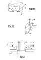
- Figure 4a is a schematic view of a cooling hole angled within a liner wall according to this invention.
- Figure 4b is a cooling hole angled in a circumferential direction within a liner wall according to this invention.
- Figure 5 is a schematic representation of the effects of three-dimensional flow through openings within a liner wall according to this invention.
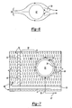
- Figure 6 is another schematic representation of coolant airflow around a dilution hole according to this invention.
- Figure 7 is a schematic representation of a portion of the liner assembly according to this invention.
- Referring to Figure 1, a
turbine engine assembly 10 includes a fan, acompressor 12 that feeds compressed air to acombustor 14. Compressed air is mixed with fuel and ignited within the combustor to produce hot gasses that are then driven past aturbine 16. The schematic representation of theturbine engine assembly 10 is intended for descriptive purposes, as other turbine engine assembly configurations will also benefit from the disclosures of this invention. - Referring to Figure 2, the
combustor assembly 14 includes a dual-wall liner assembly 15. Theliner assembly 15 includes aninner shell 22 and anouter shell 24. Theouter shell 24 andinner shell 22 are spaced radially apart from aninner heat shield 26 and anouter heat shield 28. Theinner shell 22 andouter shell 24 are spaced a radial distance apart to define anair passage 20 between theouter heat shield 28 and theinner heat shield 26. - The example combustor assembly illustrated is disposed annularly about the
axis 18. The radial space in between theshells heat shields air passage 20.Cooling air 36 flows through theair passage 20 to provide cooling for theheat shields heat shields bulkhead assembly 25. The combustion chamber 34 is defined by theheat shields aft end 27 to allow the exhaust of combustion gasses. - A layer of cooling air is supplied along a
hot side surface heat shields Cooling air 36 is communicated from acold side heat shields hot side hot side surfaces aft end 27 to provide insulation for theheat shields - Each of the
heat shields dilution air openings 32 andcooling air openings 30. Thecooling air openings 30 are disposed within theheat shields dilution openings 32 that provide air to aid the combustion process. Thedilution openings 32 are much larger than thecooling air openings 30. Airflow through thedilution holes 32 can disrupt the cooling airflow along the surfaces of theheat shields - Referring to Figure 3, the
inner heat shield 26 includes thehot side surface 42 and thecold side surface 44.Cooling air 36 flows from thecold side surface 44 to thehot side surface 42. Thedilution opening 32 is much larger than the coolingopenings 32. Further, within the portion of theheat shield 26 are arail assembly 38 and aseam 40. Therail assembly 38 and theseam 40 are areas in the liner assembly of non-uniform material thickness that creates specific challenges to maintaining uniform temperatures of theheat shield 26. - The cooling holes 30 are distributed in a substantially uniform geometric pattern and density within the
heat shield 26. However, in locations proximate to the various structural features such as thedilution opening 32, therail assembly 38 and theseam 40, the cooling holes 30 are distributed in a non-uniform matter to facilitatecooling air flow 36 adjacent these features of theliner assembly 15. - A
first group 58 of cooling holes 30 is disposed in a generally uniform geometric pattern within afirst region 60. Thefirst region 60 includes all of the regions within theheat shield 26 that are not disposed adjacent one of the structural features such as therail 38 or thedilution opening 32. Asecond region 64 is disposed between thefirst region 60 and thedilution opening 32. - Each of the cooling holes 30 is disposed at an angular orientation from the
cold side 44 to thehot side 42 of theinner heat shield 26. The angular orientation provides the directional flow of the coolingairflow 36, thereby generating the insulating layer of air along thehot side 42. Each of the cooling holes 30 is disposed at a compound angle including aninclination angle 54 and acircumferential angle 56. Theinclination angle 54 is disposed relative to alongitudinal axis 50 of thecombustor assembly 14. Thecircumferential angle 56 is disposed relative to a transverse orcircumferential axis 52 disposed transverse to the to theaxis 50. Each coolinghole 30 is disposed within theheat shield 26 at the compound angle including components angled relative to thelongitudinal axis 50 and thecircumferential axis 52. Tailoring of theinclination angle 54 andcircumferential angle 56 provides for directing airflow over areas along thehot side surface 42. - Referring to Figure 4a a large schematic view of a
cooling hole 30 disposed within theinner heat shield 26 is shown. Thecooling hole 30 is disposed at the inclination angle indicated at 54. Preferably, the inclination angle is within a range about 15 to 45 degrees. More preferably theinclination angle 54 is between 20 and 30 degrees. The specification inclination angle for the cooling holes 30 is maintained for each of the cooling holes 30 disposed within theliner assembly 15 according to this invention. - Referring to Figure 4b, each of the cooling holes 30 are also disposed at a circumferential or
clock angle 56 that is transverse to theaxis 18. Theclock angle 56 can vary by as much as 90 degrees relative to theaxis 52. - The cooling holes 30 include a diameter of approximately 0.02-0.03 inches (0.51-0.76 mm) and are arranged with circumferential and axial spacing of between 2 to 10 hole diameters. Similar spacing both axially and circumferentially form a geometrically uniform pattern. The regular and repeatable cooling hole spacing works well in many regions of the liner assembly. However, in regions of the liner assembly that are located proximate to structural features such as the dilutions holes 32, rails 38 and
seams 40 that may suffer a loss of cooling film effectiveness require a different cooling hole angular orientation. A non-uniform cooling hole array in these regions is provided to control temperatures in theheat shield 26 proximate thedilution openings 32, therail assemblies 38 and theseams 40. - Referring to Figure 5 and 6, compressed air flow flowing through larger openings such as the
dilution opening 32 can generate three-dimensional airflows along thehot side surface 42. Three-dimensional airflow schematically indicated at 37 disrupts coolingairflow 36 adjacent the surfaces of the inner andouter heat shield Flow 37 through thedilution openings 32 causes thecooling airflow 36 to stagnate and generates three-dimensional or recirculating flows indicated at 39. Three-dimensional recirculating flows drive coolingair 36 away from the surface areas in the vicinity of thelarger dilution openings 32 and locally depress or siphon cooling airflow away from the cooling holes. These factors reduce cooling effectiveness around the cooling hole feature anddilution openings 32. The upstream airflow migrates around theair flow 37 is at a significant momentum to produce complex gradients that reduces cooling effectiveness. - Referring to Figure 7, the
liner assembly 15 includes a non-uniform grouping of cooling holes proximate to the structural features that can potentially disrupt cooling airflow. Thefirst group 58 of cooling holes 30 is disposed within thefirst region 60. Thefirst region 60 is disposed in locations throughout the liner assembly and comprises the majority of cooling holes 30 within theheat shields first group 58, in thefirst region 60, the cooling holes 30 are disposed in a uniform repeating geometric pattern. Each of the cooling holes 30 within thefirst group 58 includes anidentical inclination angle 54 andcircumferential angle 56. - The
inclination angle 54 and the circumferential 56 of the cooling holes 30 in thefirst group 58 provides the desired directional flow of cooling air along thehot side surface 42 of theheat shields - Between the
first group 58 and structural features such as therail 38 andflange 72 are asecond group 62 of cooling holes 30. Thesecond group 62 is disposed in asecond region 64 between thefirst region 60 and thedilution opening 32. Thedilution opening 32 is most often accompanied by agrommet 35 that increases the thickness proximate thedilution opening 32. Thegrommet 35 provides an isolating chamber for the dilution flow, sealing of the chamber between the liner and heat shield and a standoff to maintain the gap between the liner and heat shield. In thesecond region 64, the second group of cooling holes 30 include aninclination angle 54 equal to those of theinclination angle 54 of thefirst group 58. - The circumferential angle of the
second group 62 differs from the circumferential angle of thefirst group 58. The circumferential angle within the second group is preferably disposed such that each of the cooling holes is disposed in a tangential orientation relative to an outer perimeter 63 of thedilution opening 32. The tangential orientation of the coolingopenings 30 provides a directionally non-uniform or circumferential cooling airflow about the perimeter 63 of thedilution opening 32. The directional flow of coolingair 36 proximate to thedilution opening 32 provides the desired accommodation for cooling airflow that provides uniform temperatures within theheat shield 26. - A third region 66 is disposed between the
first region 60 and therail 38. Therail 38 is an area of increased thickness that also requires preferential and non-uniform cooling with respect and compared to thefirst group 60. Thethird group 68 is disposed between thefirst group 60 and therail assembly 38. In the third group, the cooling holes 30 are disposed at a uniform circumferential angle along therail 38. The circumferential angle of the cooling holes 30 in thethird group 68 is different than those in thefirst group 60. The circumferential angle of thethird group 68 of cooling holes is substantially parallel to therail assembly 38 to direct coolingairflow 36 across the rail. - A
fourth group 72 is disposed within afourth region 70 that is disposed between thefirst group 60 and theseam 40. About theseam 40 each of the cooling holes 30 are alternately disposed at a circumferential angle different than an immediately adjacent coolinghole 30. In the illustrative embodiment each of the cooling holes 30 are disposed at an angle that crosses at an outer boundary of theseam 40. The cooling holes 30 are disposed with circumferential angles disposed in an opposing manner to the circumferential angle of cooling holes 30 disposed on an opposite side of theseam 40. The alternating pattern of coolinghole 30 angles providescooling airflow 36 longitudinally along theseam 40 with a hole density substantially equal to the density of thefirst group 58. This provides the preferential direction of the cooling air required for the non-uniform thickness within theseam area 40. - Circumferential orientation and these non-uniform regions may vary by as much as 180 degrees with
cooling holes 30 that are preferentially positioned. The inclination angle of these holes is similar to those of adjacent grouping and within a tolerance of +-5 degrees. The use of the same hole diameter and minimal changes to the inclination angle permits machining operations to be performed continually without requiring additional set up operations. This also provides for the increased cooling effectiveness that accommodates added mass proximate therail 38 andseam 40 along with accommodating three dimensional flows produced bylarger dilution openings 32. - Although a preferred embodiment of this invention has been disclosed, a worker of ordinary skill in this art would recognize that certain modifications would come within the scope of this invention. For that reason, the following claims should be studied to determine the true scope and content of this invention.
Claims (20)
- A liner assembly (15) comprising:a liner including an inner surface having at least one surface feature (32, 38, 40);a first group (58) of cooling holes formed in said liner having a first circumferential angle (56) and first inclination angle (54) relative to a surface of said liner, said first group of cooling holes (60) spaced a distance apart from said surface feature; anda second group (62; 68; 72) of cooling holes disposed within a region between said first group of cooling holes (58) and said surface feature (32, 38, 40), wherein each of said second group (62; 68; 72) of cooling holes is disposed in a second circumferential angle (56) different than said first circumferential angle (56) and a second inclination angle (54) equal to said first inclination angle (54).
- The assembly as recited in claim 1, wherein said surface feature comprises an opening (32) for emitting a flow stream through said liner assembly (15) wherein said second circumferential angle (56) is different for each of said second group (68) of cooling holes proximate said opening (32).
- The assembly as recited in claim 2, wherein said opening (32) is circular and at least some of said second group (62) of cooling holes includes a circumferential angle (56) substantially tangent to a perimeter (63) of said opening (32).
- The assembly as recited in claim 3, wherein at least some of said second group (62) of cooling holes is disposed adjacent a perimeter (63) of said opening (32).
- The assembly as recited in claim 1, wherein said surface feature comprises a rail (38), wherein said second group (68) of cooling holes are disposed across said rail (38).
- The assembly as recited in claim 5, wherein said rail (38) defines a perimeter and said second group of cooling holes (68) are disposed at least partially within said perimeter.
- The assembly as recited in claim 5, wherein at least some of said second group (68) of cooling holes comprise a circumferential angle (56) that is disposed relative to a perimeter of said rail (38).
- The assembly as recited in claim 1, wherein said surface feature comprises a linear flange (38; 40) and said second group (68; 72) of cooling holes includes a common circumferential angle (56) that is different than said first circumferential angle (56).
- The assembly as recited in any preceding claim, wherein said first group (60) of cooling holes includes a substantially equal spacing circumferentially and linearly, and said second group of cooling holes (60; 68; 72) includes a substantially non-equal spacing circumferentially and axially.
- A liner assembly (15) for a gas turbine engine comprising:a surface defining a gas flow path and including a structural feature (32; 38; 40) creating localized temperature non-uniformity within said surface;a first plurality (58) of cooling holes spaced apart to define a first hole density, wherein each of said first plurality (58) of cooling holes include a first inclination angle (54) relative to a longitudinal axis, and a first circumferential angle (56) transverse to said longitudinal axis; anda second plurality (62; 68; 72) of cooling holes disposed between said first plurality (58) of cooling holes and said structural feature (32; 38; 40), said second plurality (62; 68; 72) of cooling holes spaced apart at a hole density substantially equal to said first hole density, wherein each of said second plurality (60; 68; 72) of cooling holes includes a second inclination angle (54) substantially equal to said first inclination angle (54) and a second circumferential angle (56) different than said first circumferential angle (56).
- The assembly as recited in claim 10, wherein said second circumferential angle (56) is disposed relative to said structural feature.
- The assembly as recited in claim 11, wherein said structural feature comprises an opening (32), and said second circumferential angle (56) is disposed tangentially to a perimeter (63) of said opening (32).
- The assembly as recited in claim 11, wherein said structural feature comprises a rail (38) and said second circumferential angle (56) is disposed parallel to said rail (38).
- The assembly as recited in claim 11, wherein said structural feature comprises a rail (38) and said second circumferential angle (56) is disposed transverse to said rail (38).
- The assembly as recited in claim 11, wherein said structural feature comprises a seam (40), and said second circumferential angle (56) is disposed at an angle relative to said seam.
- The assembly as recited in claim 15, wherein cooling holes proximate said seam (40) are disposed at opposite angles on opposing sides of said seam (40).
- A method of controlling a temperature of a liner surface proximate a structural feature (32; 38; 40) within the liner surface, said method comprising the steps of:a) generating a first cooling air flow through a first plurality (58) of cooling holes having a first hole density;b) generating a second cooling air flow through a second plurality (62; 68; 72) of cooling holes disposed between said first plurality (58) of cooling holes and the structural feature (32; 38; 40);c) selectively orientating a circumferential angle (56) of each of the second plurality (62; 68; 72) of cooling holes relative to the structural feature (32; 38; 40); andd) maintaining the first hole density within the second plurality (62; 68; 72) of cooling holes.
- The method as recited in claim 17, including the step of orientating an inclination angle (54) for each of the first plurality (58) of cooling holes and the second plurality (62; 68; 72) of cooling holes at a substantially common direction.
- The method as recited in claim 17, including the step of orientating the circumferential angle (56) of the second plurality (62) of cooling holes tangent to the structural feature (32).
- The method as recited in claim 18, including the step of orientating the circumferential angle (56) of the second plurality of cooling holes perpendicular to the structural feature.
Applications Claiming Priority (1)
| Application Number | Priority Date | Filing Date | Title |
|---|---|---|---|
| US11/302,586 US7631502B2 (en) | 2005-12-14 | 2005-12-14 | Local cooling hole pattern |
Publications (3)
| Publication Number | Publication Date |
|---|---|
| EP1798474A2 true EP1798474A2 (en) | 2007-06-20 |
| EP1798474A3 EP1798474A3 (en) | 2010-06-30 |
| EP1798474B1 EP1798474B1 (en) | 2016-03-02 |
Family
ID=37758673
Family Applications (1)
| Application Number | Title | Priority Date | Filing Date |
|---|---|---|---|
| EP06256259.0A Active EP1798474B1 (en) | 2005-12-14 | 2006-12-08 | Local cooling hole pattern |
Country Status (5)
| Country | Link |
|---|---|
| US (1) | US7631502B2 (en) |
| EP (1) | EP1798474B1 (en) |
| JP (1) | JP2007163130A (en) |
| IL (1) | IL180063A0 (en) |
| RU (1) | RU2006144596A (en) |
Cited By (4)
| Publication number | Priority date | Publication date | Assignee | Title |
|---|---|---|---|---|
| DE102008026463A1 (en) * | 2008-06-03 | 2009-12-10 | E.On Ruhrgas Ag | Combustion device for gas turbine system in natural gas pipeline network, has cooling arrays arranged over circumference of central body, distributed at preset position on body, and provided adjacent to primary fuel injectors |
| CN104364581A (en) * | 2012-06-13 | 2015-02-18 | 通用电气公司 | Gas turbine engine wall |
| EP3077728A4 (en) * | 2013-12-06 | 2016-11-30 | United Technologies Corp | Co-swirl orientation of combustor effusion passages for gas turbine engine combustor |
| CN108290198A (en) * | 2015-01-09 | 2018-07-17 | 哈佛大学校董委员会 | Have the projection slit of distortion to provide the auxetic structure of NPR characteristics and improved stress performance to be engineered pattern |
Families Citing this family (43)
| Publication number | Priority date | Publication date | Assignee | Title |
|---|---|---|---|---|
| US7614235B2 (en) * | 2005-03-01 | 2009-11-10 | United Technologies Corporation | Combustor cooling hole pattern |
| US7954326B2 (en) * | 2007-11-28 | 2011-06-07 | Honeywell International Inc. | Systems and methods for cooling gas turbine engine transition liners |
| US20090188256A1 (en) * | 2008-01-25 | 2009-07-30 | Honeywell International Inc. | Effusion cooling for gas turbine combustors |
| US8091367B2 (en) * | 2008-09-26 | 2012-01-10 | Pratt & Whitney Canada Corp. | Combustor with improved cooling holes arrangement |
| US20100095680A1 (en) * | 2008-10-22 | 2010-04-22 | Honeywell International Inc. | Dual wall structure for use in a combustor of a gas turbine engine |
| US20100159132A1 (en) * | 2008-12-18 | 2010-06-24 | Veeco Instruments, Inc. | Linear Deposition Source |
| US9897320B2 (en) * | 2009-07-30 | 2018-02-20 | Honeywell International Inc. | Effusion cooled dual wall gas turbine combustors |
| US8813501B2 (en) | 2011-01-03 | 2014-08-26 | General Electric Company | Combustor assemblies for use in turbine engines and methods of assembling same |
| US9062884B2 (en) | 2011-05-26 | 2015-06-23 | Honeywell International Inc. | Combustors with quench inserts |
| FR2979416B1 (en) * | 2011-08-26 | 2013-09-20 | Turbomeca | WALL OF COMBUSTION CHAMBER |
| US11143030B2 (en) | 2012-12-21 | 2021-10-12 | Raytheon Technologies Corporation | Coating process for gas turbine engine component with cooling holes |
| WO2014112992A1 (en) | 2013-01-16 | 2014-07-24 | United Technologies Corporation | Combustor cooled quench zone array |
| EP2950942B1 (en) | 2013-01-30 | 2019-06-26 | United Technologies Corporation | Coating process for gas turbine engine component with cooling holes |
| US9366187B2 (en) | 2013-03-12 | 2016-06-14 | Pratt & Whitney Canada Corp. | Slinger combustor |
| WO2014197045A2 (en) * | 2013-03-12 | 2014-12-11 | United Technologies Corporation | Active cooling of grommet bosses for a combustor panel of a gas turbine engine |
| US9127843B2 (en) | 2013-03-12 | 2015-09-08 | Pratt & Whitney Canada Corp. | Combustor for gas turbine engine |
| US9228747B2 (en) | 2013-03-12 | 2016-01-05 | Pratt & Whitney Canada Corp. | Combustor for gas turbine engine |
| US9958161B2 (en) * | 2013-03-12 | 2018-05-01 | Pratt & Whitney Canada Corp. | Combustor for gas turbine engine |
| US9541292B2 (en) | 2013-03-12 | 2017-01-10 | Pratt & Whitney Canada Corp. | Combustor for gas turbine engine |
| US9709274B2 (en) | 2013-03-15 | 2017-07-18 | Rolls-Royce Plc | Auxetic structure with stress-relief features |
| WO2014143209A1 (en) | 2013-03-15 | 2014-09-18 | Rolls-Royce Corporation | Gas turbine engine combustor liner |
| US9879861B2 (en) | 2013-03-15 | 2018-01-30 | Rolls-Royce Corporation | Gas turbine engine with improved combustion liner |
| US11112115B2 (en) | 2013-08-30 | 2021-09-07 | Raytheon Technologies Corporation | Contoured dilution passages for gas turbine engine combustor |
| EP3066388B1 (en) | 2013-11-04 | 2024-04-10 | RTX Corporation | Turbine engine combustor heat shield with multi-angled cooling apertures |
| WO2015065587A1 (en) | 2013-11-04 | 2015-05-07 | United Technologies Corporation | Coated cooling passage |
| US10317079B2 (en) | 2013-12-20 | 2019-06-11 | United Technologies Corporation | Cooling an aperture body of a combustor wall |
| US9851105B2 (en) | 2014-07-03 | 2017-12-26 | United Technologies Corporation | Self-cooled orifice structure |
| US9810148B2 (en) | 2014-07-24 | 2017-11-07 | United Technologies Corporation | Self-cooled orifice structure |
| US9897318B2 (en) | 2014-10-29 | 2018-02-20 | General Electric Company | Method for diverting flow around an obstruction in an internal cooling circuit |
| US10612781B2 (en) | 2014-11-07 | 2020-04-07 | United Technologies Corporation | Combustor wall aperture body with cooling circuit |
| US20160258623A1 (en) * | 2015-03-05 | 2016-09-08 | United Technologies Corporation | Combustor and heat shield configurations for a gas turbine engine |
| US9746184B2 (en) * | 2015-04-13 | 2017-08-29 | Pratt & Whitney Canada Corp. | Combustor dome heat shield |
| EP3109550B1 (en) | 2015-06-19 | 2019-09-04 | Rolls-Royce Corporation | Turbine cooled cooling air flowing through a tubular arrangement |
| CA2933884A1 (en) | 2015-06-30 | 2016-12-30 | Rolls-Royce Corporation | Combustor tile |
| JP6026028B1 (en) * | 2016-03-10 | 2016-11-16 | 三菱日立パワーシステムズ株式会社 | Combustor panel, combustor, combustion apparatus, gas turbine, and method for cooling combustor panel |
| US10670269B2 (en) | 2016-10-26 | 2020-06-02 | Raytheon Technologies Corporation | Cast combustor liner panel gating feature for a gas turbine engine combustor |
| US10753283B2 (en) * | 2017-03-20 | 2020-08-25 | Pratt & Whitney Canada Corp. | Combustor heat shield cooling hole arrangement |
| US11313560B2 (en) | 2018-07-18 | 2022-04-26 | General Electric Company | Combustor assembly for a heat engine |
| US11187412B2 (en) | 2018-08-22 | 2021-11-30 | General Electric Company | Flow control wall assembly for heat engine |
| US11029027B2 (en) * | 2018-10-03 | 2021-06-08 | Raytheon Technologies Corporation | Dilution/effusion hole pattern for thick combustor panels |
| US11391460B2 (en) | 2019-07-16 | 2022-07-19 | Raytheon Technologies Corporation | Effusion cooling for dilution/quench hole edges in combustor liner panels |
| US11199326B2 (en) | 2019-12-20 | 2021-12-14 | Raytheon Technologies Corporation | Combustor panel |
| CN115614775B (en) * | 2022-08-26 | 2024-06-18 | 西安航天动力研究所 | Cooling unit for improving flow uniformity of cooling channel and regeneratively cooled combustion chamber |
Citations (5)
| Publication number | Priority date | Publication date | Assignee | Title |
|---|---|---|---|---|
| US5261223A (en) * | 1992-10-07 | 1993-11-16 | General Electric Company | Multi-hole film cooled combustor liner with rectangular film restarting holes |
| EP1001222A2 (en) * | 1998-11-13 | 2000-05-17 | General Electric Company | Multi-hole film cooled combustor liner |
| EP1195559A2 (en) * | 2000-10-03 | 2002-04-10 | General Electric Company | Combustor liner having cooling holes with different orientations |
| US6513331B1 (en) * | 2001-08-21 | 2003-02-04 | General Electric Company | Preferential multihole combustor liner |
| EP1363075A2 (en) * | 2002-05-16 | 2003-11-19 | United Technologies Corporation | Heat shield panels for use in a combustor for a gas turbine engine |
Family Cites Families (16)
| Publication number | Priority date | Publication date | Assignee | Title |
|---|---|---|---|---|
| JPS6082281A (en) | 1983-10-07 | 1985-05-10 | Agency Of Ind Science & Technol | Production of combustor for gas turbine |
| US5233828A (en) | 1990-11-15 | 1993-08-10 | General Electric Company | Combustor liner with circumferentially angled film cooling holes |
| US5241827A (en) * | 1991-05-03 | 1993-09-07 | General Electric Company | Multi-hole film cooled combuster linear with differential cooling |
| JPH0875166A (en) | 1994-09-07 | 1996-03-19 | Hitachi Ltd | Manufacture of liner for gas turbine burner |
| JPH08135968A (en) | 1994-11-08 | 1996-05-31 | Toshiba Corp | Gas turbine combustor |
| DE19502328A1 (en) | 1995-01-26 | 1996-08-01 | Bmw Rolls Royce Gmbh | Heat shield for a gas turbine combustor |
| FR2733582B1 (en) * | 1995-04-26 | 1997-06-06 | Snecma | COMBUSTION CHAMBER COMPRISING VARIABLE AXIAL AND TANGENTIAL TILT MULTIPERFORATION |
| US6145319A (en) * | 1998-07-16 | 2000-11-14 | General Electric Company | Transitional multihole combustion liner |
| US6266961B1 (en) * | 1999-10-14 | 2001-07-31 | General Electric Company | Film cooled combustor liner and method of making the same |
| US6434821B1 (en) * | 1999-12-06 | 2002-08-20 | General Electric Company | Method of making a combustion chamber liner |
| JP3445583B2 (en) * | 2001-06-29 | 2003-09-08 | 株式会社東芝 | Flexible printed circuit board connector, head actuator provided with the same, and disk device |
| US6655146B2 (en) * | 2001-07-31 | 2003-12-02 | General Electric Company | Hybrid film cooled combustor liner |
| US7086232B2 (en) * | 2002-04-29 | 2006-08-08 | General Electric Company | Multihole patch for combustor liner of a gas turbine engine |
| JP4068432B2 (en) * | 2002-11-07 | 2008-03-26 | 株式会社日立製作所 | Gas turbine combustor |
| US7216485B2 (en) * | 2004-09-03 | 2007-05-15 | General Electric Company | Adjusting airflow in turbine component by depositing overlay metallic coating |
| US7614235B2 (en) * | 2005-03-01 | 2009-11-10 | United Technologies Corporation | Combustor cooling hole pattern |
-
2005
- 2005-12-14 US US11/302,586 patent/US7631502B2/en active Active
-
2006
- 2006-12-08 EP EP06256259.0A patent/EP1798474B1/en active Active
- 2006-12-13 JP JP2006335290A patent/JP2007163130A/en active Pending
- 2006-12-14 IL IL180063A patent/IL180063A0/en unknown
- 2006-12-14 RU RU2006144596/06A patent/RU2006144596A/en not_active Application Discontinuation
Patent Citations (5)
| Publication number | Priority date | Publication date | Assignee | Title |
|---|---|---|---|---|
| US5261223A (en) * | 1992-10-07 | 1993-11-16 | General Electric Company | Multi-hole film cooled combustor liner with rectangular film restarting holes |
| EP1001222A2 (en) * | 1998-11-13 | 2000-05-17 | General Electric Company | Multi-hole film cooled combustor liner |
| EP1195559A2 (en) * | 2000-10-03 | 2002-04-10 | General Electric Company | Combustor liner having cooling holes with different orientations |
| US6513331B1 (en) * | 2001-08-21 | 2003-02-04 | General Electric Company | Preferential multihole combustor liner |
| EP1363075A2 (en) * | 2002-05-16 | 2003-11-19 | United Technologies Corporation | Heat shield panels for use in a combustor for a gas turbine engine |
Cited By (7)
| Publication number | Priority date | Publication date | Assignee | Title |
|---|---|---|---|---|
| DE102008026463A1 (en) * | 2008-06-03 | 2009-12-10 | E.On Ruhrgas Ag | Combustion device for gas turbine system in natural gas pipeline network, has cooling arrays arranged over circumference of central body, distributed at preset position on body, and provided adjacent to primary fuel injectors |
| CN104364581A (en) * | 2012-06-13 | 2015-02-18 | 通用电气公司 | Gas turbine engine wall |
| CN104364581B (en) * | 2012-06-13 | 2016-05-18 | 通用电气公司 | Gas-turbine unit wall |
| US10386069B2 (en) | 2012-06-13 | 2019-08-20 | General Electric Company | Gas turbine engine wall |
| EP3077728A4 (en) * | 2013-12-06 | 2016-11-30 | United Technologies Corp | Co-swirl orientation of combustor effusion passages for gas turbine engine combustor |
| CN108290198A (en) * | 2015-01-09 | 2018-07-17 | 哈佛大学校董委员会 | Have the projection slit of distortion to provide the auxetic structure of NPR characteristics and improved stress performance to be engineered pattern |
| EP3242759A4 (en) * | 2015-01-09 | 2018-09-26 | President and Fellows of Harvard College | Auxetic structures with distorted projection slots in engineered patterns to provide npr behavior and improved stress performance |
Also Published As
| Publication number | Publication date |
|---|---|
| RU2006144596A (en) | 2008-06-20 |
| US7631502B2 (en) | 2009-12-15 |
| IL180063A0 (en) | 2007-10-31 |
| US20070130953A1 (en) | 2007-06-14 |
| EP1798474B1 (en) | 2016-03-02 |
| JP2007163130A (en) | 2007-06-28 |
| EP1798474A3 (en) | 2010-06-30 |
Similar Documents
| Publication | Publication Date | Title |
|---|---|---|
| EP1798474B1 (en) | Local cooling hole pattern | |
| US7905094B2 (en) | Combustor systems with liners having improved cooling hole patterns | |
| US6568187B1 (en) | Effusion cooled transition duct | |
| EP1705426B1 (en) | Combustor cooling hole pattern | |
| EP1556596B8 (en) | Effusion cooled transition duct with shaped cooling holes | |
| EP2330350B1 (en) | Dual walled combustors with impingement cooled igniters | |
| US7386980B2 (en) | Combustion liner with enhanced heat transfer | |
| US8056346B2 (en) | Combustor | |
| EP3521703B1 (en) | Undercut combustor liner panel | |
| EP3628927B1 (en) | Heat shield panel | |
| US11359812B2 (en) | Multi-direction hole for rail effusion | |
| EP3521704B1 (en) | Heat shield | |
| CA2949066A1 (en) | Combustion liner with bias effusion cooling | |
| EP3604926B1 (en) | Heat shield panel for use in a gas turbine engine combustor |
Legal Events
| Date | Code | Title | Description |
|---|---|---|---|
| PUAI | Public reference made under article 153(3) epc to a published international application that has entered the european phase |
Free format text: ORIGINAL CODE: 0009012 |
|
| AK | Designated contracting states |
Kind code of ref document: A2 Designated state(s): AT BE BG CH CY CZ DE DK EE ES FI FR GB GR HU IE IS IT LI LT LU LV MC NL PL PT RO SE SI SK TR |
|
| AX | Request for extension of the european patent |
Extension state: AL BA HR MK YU |
|
| PUAL | Search report despatched |
Free format text: ORIGINAL CODE: 0009013 |
|
| AK | Designated contracting states |
Kind code of ref document: A3 Designated state(s): AT BE BG CH CY CZ DE DK EE ES FI FR GB GR HU IE IS IT LI LT LU LV MC NL PL PT RO SE SI SK TR |
|
| AX | Request for extension of the european patent |
Extension state: AL BA HR MK RS |
|
| 17P | Request for examination filed |
Effective date: 20101223 |
|
| AKX | Designation fees paid |
Designated state(s): DE GB |
|
| 17Q | First examination report despatched |
Effective date: 20131010 |
|
| GRAP | Despatch of communication of intention to grant a patent |
Free format text: ORIGINAL CODE: EPIDOSNIGR1 |
|
| INTG | Intention to grant announced |
Effective date: 20150804 |
|
| GRAS | Grant fee paid |
Free format text: ORIGINAL CODE: EPIDOSNIGR3 |
|
| GRAA | (expected) grant |
Free format text: ORIGINAL CODE: 0009210 |
|
| AK | Designated contracting states |
Kind code of ref document: B1 Designated state(s): DE GB |
|
| REG | Reference to a national code |
Ref country code: GB Ref legal event code: FG4D |
|
| REG | Reference to a national code |
Ref country code: DE Ref legal event code: R081 Ref document number: 602006048067 Country of ref document: DE Owner name: UNITED TECHNOLOGIES CORP. (N.D.GES.D. STAATES , US Free format text: FORMER OWNER: UNITED TECHNOLOGIES CORP. (N.D.GES.D. STAATES DELAWARE), HARTFORD, CONN., US |
|
| REG | Reference to a national code |
Ref country code: DE Ref legal event code: R096 Ref document number: 602006048067 Country of ref document: DE |
|
| RAP2 | Party data changed (patent owner data changed or rights of a patent transferred) |
Owner name: UNITED TECHNOLOGIES CORPORATION |
|
| REG | Reference to a national code |
Ref country code: DE Ref legal event code: R097 Ref document number: 602006048067 Country of ref document: DE |
|
| PLBE | No opposition filed within time limit |
Free format text: ORIGINAL CODE: 0009261 |
|
| STAA | Information on the status of an ep patent application or granted ep patent |
Free format text: STATUS: NO OPPOSITION FILED WITHIN TIME LIMIT |
|
| 26N | No opposition filed |
Effective date: 20161205 |
|
| REG | Reference to a national code |
Ref country code: DE Ref legal event code: R082 Ref document number: 602006048067 Country of ref document: DE Representative=s name: SCHMITT-NILSON SCHRAUD WAIBEL WOHLFROM PATENTA, DE |
|
| REG | Reference to a national code |
Ref country code: DE Ref legal event code: R082 Ref document number: 602006048067 Country of ref document: DE Representative=s name: SCHMITT-NILSON SCHRAUD WAIBEL WOHLFROM PATENTA, DE Ref country code: DE Ref legal event code: R081 Ref document number: 602006048067 Country of ref document: DE Owner name: UNITED TECHNOLOGIES CORP. (N.D.GES.D. STAATES , US Free format text: FORMER OWNER: UNITED TECHNOLOGIES CORPORATION, HARTFORD, CONN., US |
|
| REG | Reference to a national code |
Ref country code: DE Ref legal event code: R081 Ref document number: 602006048067 Country of ref document: DE Owner name: RAYTHEON TECHNOLOGIES CORPORATION (N.D.GES.D.S, US Free format text: FORMER OWNER: UNITED TECHNOLOGIES CORP. (N.D.GES.D. STAATES DELAWARE), FARMINGTON, CONN., US |
|
| P01 | Opt-out of the competence of the unified patent court (upc) registered |
Effective date: 20230519 |
|
| PGFP | Annual fee paid to national office [announced via postgrant information from national office to epo] |
Ref country code: GB Payment date: 20231121 Year of fee payment: 18 |
|
| PGFP | Annual fee paid to national office [announced via postgrant information from national office to epo] |
Ref country code: DE Payment date: 20231121 Year of fee payment: 18 |