EP1798460A1 - Mehrfach-Kupplung für Medienleitungen - Google Patents
Mehrfach-Kupplung für Medienleitungen Download PDFInfo
- Publication number
- EP1798460A1 EP1798460A1 EP06125122A EP06125122A EP1798460A1 EP 1798460 A1 EP1798460 A1 EP 1798460A1 EP 06125122 A EP06125122 A EP 06125122A EP 06125122 A EP06125122 A EP 06125122A EP 1798460 A1 EP1798460 A1 EP 1798460A1
- Authority
- EP
- European Patent Office
- Prior art keywords
- coupling
- parts
- plug
- coupling part
- screw
- Prior art date
- Legal status (The legal status is an assumption and is not a legal conclusion. Google has not performed a legal analysis and makes no representation as to the accuracy of the status listed.)
- Granted
Links
Images

Classifications
-
- F—MECHANICAL ENGINEERING; LIGHTING; HEATING; WEAPONS; BLASTING
- F16—ENGINEERING ELEMENTS AND UNITS; GENERAL MEASURES FOR PRODUCING AND MAINTAINING EFFECTIVE FUNCTIONING OF MACHINES OR INSTALLATIONS; THERMAL INSULATION IN GENERAL
- F16L—PIPES; JOINTS OR FITTINGS FOR PIPES; SUPPORTS FOR PIPES, CABLES OR PROTECTIVE TUBING; MEANS FOR THERMAL INSULATION IN GENERAL
- F16L39/00—Joints or fittings for double-walled or multi-channel pipes or pipe assemblies
-
- F—MECHANICAL ENGINEERING; LIGHTING; HEATING; WEAPONS; BLASTING
- F16—ENGINEERING ELEMENTS AND UNITS; GENERAL MEASURES FOR PRODUCING AND MAINTAINING EFFECTIVE FUNCTIONING OF MACHINES OR INSTALLATIONS; THERMAL INSULATION IN GENERAL
- F16L—PIPES; JOINTS OR FITTINGS FOR PIPES; SUPPORTS FOR PIPES, CABLES OR PROTECTIVE TUBING; MEANS FOR THERMAL INSULATION IN GENERAL
- F16L37/00—Couplings of the quick-acting type
- F16L37/56—Couplings of the quick-acting type for double-walled or multi-channel pipes or pipe assemblies
Definitions
- the present invention relates to a multiple coupling for media lines, with (at least) a plate-like coupling part having a plurality (ie at least two) receptacles for fixed mounting of a respective plug-in coupling part such that the plug-in coupling parts by means of the coupling part in pairs with corresponding counter-plug coupling parts Connectors are detachable.
- Such multiple couplings have the advantage that by means of the common coupling part a plurality of plug-in couplings can be coupled simultaneously in a common coupling operation.
- the present invention has for its object to provide a multiple clutch of the type mentioned, which allows a simpler installation while maintaining the advantages of known designs, even in tight spaces.
- the coupling part is made in several parts of at least two - preferably identical - moldings, each having a subset of the existing receptacles for the plug-in coupling parts and separated in the uncoupled state or separable.
- Erten counter plug-in coupling parts can be coupled by plug connection.
- the molded parts of the coupling part lie next to one another in a common plane and can be fixed in a suitable manner.
- screws are used to pass through the through openings of the moldings and engage in threaded holes on the side of a counter-plug coupling parts having counter-coupling part.
- the counter-coupling part can directly from an aggregate, z.
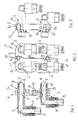
- a multiple coupling 1 has a plate-like coupling part 2 which in turn has a plurality of four receptacles 4 in the illustrated embodiment (see the section in FIG. 4) for fixed mounting of one plug-in coupling part 6 such that the plug-in coupling parts 6 by means of the coupling part 2 pairs with not shown corresponding counter-plug coupling parts are coupled.
- the plug-in coupling parts 6 are formed as angled plugs, each having a plug shank 8 and opposite a connecting device 10 for connecting a media line, not shown, on a coupling side.
- a pre-assembly state is illustrated with both sides releasable protective caps 12 are provided.
- the plug shafts 8 of all plug-in coupling parts 6 are arranged with respect to their stub axles 14 parallel to each other and project beyond the plate-like coupling part (coupling plate) 2 in the direction of the coupling side in order to be plugged into the mating plug-in coupling parts.
- the coupling part 2 is a multi-part, formed in the example shown from two identical mold parts 2 a and 2 b, each having a subset of existing receptacles 4 for the plug-in coupling parts 6, and which are separated according to FIG. 2a, 2b in the uncoupled state manageable. Due to the identical configuration of the mold parts 2a, 2b, these are designed to hold each half of the existing plug-in coupling parts 6, in the example shown for each two plug-in coupling parts. 6
- the molded parts 2a, 2b lie in one plane in the coupled state and are adjacent to side edges 16 (see FIGS. 2a, 2b) along a parting line 18 (FIGS. 1 and 3).
- the coupling part 2 has through openings 20 for screws, not shown, with which to secure the coupled state, the coupling part 2 with a second, the corresponding counter-plug coupling parts having Coupling part can be screwed.
- two of the through-openings 20 are preferably arranged in the region of the parting line 18 in such a way that the respective screw with a screw head proportionally covers surface areas of both adjacent molded parts 2a and 2b.
- each shaped part 2a, 2b preferably has a further through opening 20 in its approximately central area.
- the two molded parts 2a, 2b are expediently made of plastic, wherein a metal sleeve 22 is preferably inserted in the region of each screw through-opening 20 in such a way that a tightening force is mainly absorbed by the metal sleeve 22 during screwing. As a result, the surrounding plastic material is protected by too much compression by the screw.
- each plug-in coupling part 6 is fixed within the associated receptacle 4 via latching means 24, wherein these latching means 24 are automatically positively locked in the coupled state. Details of this embodiment are in the EP 0 618 393 B1 to which reference is therefore made in full at this point.
- the invention is not limited to the illustrated and described embodiments, but also includes all the same in the context of the invention embodiments. Furthermore, the invention has hitherto not been limited to the feature combination defined in claim 1, but may also be defined by any other combination of specific features of all individually disclosed individual features. This means that in principle virtually every individual feature of claim 1 can be omitted or replaced by at least one individual feature disclosed elsewhere in the application. In this respect, the claim 1 is to be understood only as a first formulation attempt for an invention.
Landscapes
- Engineering & Computer Science (AREA)
- General Engineering & Computer Science (AREA)
- Mechanical Engineering (AREA)
- Quick-Acting Or Multi-Walled Pipe Joints (AREA)
- Mechanical Operated Clutches (AREA)
- Communication Cables (AREA)
- Coupling Device And Connection With Printed Circuit (AREA)
- Transition And Organic Metals Composition Catalysts For Addition Polymerization (AREA)
Abstract
Description
- Die vorliegende Erfindung betrifft eine Mehrfach-Kupplung für Medienleitungen, mit (mindestens) einem plattenartigen Kupplungsteil, das mehrere (d. h. mindestens zwei) Aufnahmen zur fixierten Halterung von jeweils einem Steckkupplungsteil derart aufweist, dass die Steckkupplungsteile mittels des Kupplungsteils paarweise mit korrespondierenden Gegen-Steckkupplungsteilen durch Steckverbinden kuppelbar sind.
- Solche Mehrfach-Kupplungen (vgl. dazu beispielsweise die Veröffentlichungen
DE 74 21 926 U ,DE 89 08 944 U1 ,DE 89 04 141 U1 ,US 3 779 584 oderEP 0 618 393 B1 ) haben den Vorteil, dass mittels des gemeinsamen Kupplungsteils mehrere Steckkupplungen gleichzeitig in einem gemeinsamen Kupplungsvorgang gekuppelt werden können. - Die letztgenannte Veröffentlichung
EP 0 618 393 B1 beschreibt eine Kupplungseinrichtung zur Leitungsdurchführung im Bereich einer Montagewandung (sog. Schottwand) in einem Kraftfahrzeug. Vor allem bei solchen Anwendungen tritt häufig das Problem auf, dass am Montageort im Fahrzeug, insbesondere im Motorraum, bedingt durch andere benachbarte Bauteile nur wenig Platz zur Verfügung steht, was die Montage und das Kuppeln erschwert, zumal dies mit an den Steckkupplungsteilen angeschlossenen Schlauchleitungen erfolgen muß. Dieses Problem wird um so größer, je mehr Steckkupplungsteile mit angeschlossenen Leitungen vorhanden sind. - Der vorliegenden Erfindung liegt die Aufgabe zugrunde, eine Mehrfach-Kupplung der genannten Art zu schaffen, die unter Beibehaltung der Vorteile bekannter Ausführungen auch bei engen Platzverhältnissen eine vereinfache Montage ermöglicht.
- Erfindungsgemäß wird dies dadurch erreicht, dass das Kupplungsteil mehrteilig aus mindestens zwei - vorzugsweise identischen - Formteilen ausgebildet ist, die jeweils eine Teilmenge der vorhandenen Aufnahmen für die Steckkupplungsteile aufweisen und im entkuppelten Zustand von einander getrennt oder trennbar sind.
- Durch die in mindestens zwei Teile getrennte Ausbildung des plattenartigen Kupplungsteils können die darin gehalterten Steckkupplungsteile mit den angeschlossenen Leitungen besser und auch bei engen Raumverhältnissen gehandhabt werden, indem sie aus unterschiedlichen Richtungen, z. B. beidseitig an bestimmten anderen Bauteilen vorbei, zugeführt und dann mit den ortsfest (insbesondere fahrzeugseitig) gehalterten Gegen-Steckkupplungsteilen durch Steckverbinden gekuppelt werden können. Im gekuppelten Zustand liegen dann die Formteile des Kupplungsteils in einer gemeinsamen Ebene nebeneinander und können auf geeignete Weise fixiert werden. Vorzugsweise werden dazu Schrauben verwendet, die Durchführöffnungen der Formteile durchgreifen und in Gewindelöcher auf der Seite eines die Gegen-Steckkupplungsteile aufweisenden Gegen-Kupplungsteils eingreifen. Das Gegen-Kupplungsteil kann unmittelbar von einem Aggregat, z. B. einer Druckmittelquelle, gebildet oder aber plattenartig und dabei vorzugsweise gleichartig wie das erfindungsgemäße Kupplungsteil ausgebildet sein. Durch eine bevorzugt identische Ausgestaltung der Formteile können diese insbesondere als Kunststoff-Spritzgussteile auf sehr kostengünstige Weise in ein und dem selben Formwerkzeug hergestellt werden.
- Weitere vorteilhafte Ausgestaltungen der Erfindung sind in den abhängigen Ansprüchen und der folgenden Beschreibung enthalten.
- Anhand eines in der Zeichnung veranschaulichten, bevorzugten Ausführungsbeispiels soll die Erfindung genauer erläutert werden. Dabei zeigen:
- Fig. 1
- eine Perspektivansicht eines erfindungsgemäßen, mit beispielhaft vier Steckkupplungsteilen bestückten Kupplungsteils (im entkuppelten Zustand und ohne Leitungen),
- Fig. 2 a und b
- das Kupplungsteil nach Fig. 1 in einem voneinander getrennten Zustand der beiden Formteile,
- Fig. 3
- eine vergrößerte Draufsicht in Pfeilrichtung III gemäß Fig. 1,
- Fig. 4
- einen Schnitt in der Ebene A-A gemäß Fig. 3 und
- Fig. 5
- einen Schnitt in der Ebene B-B gemäß Fig. 3.
- Eine erfindungsgemäße Mehrfach-Kupplung 1 weist ein plattenartiges Kupplungsteil 2 auf, welches seinerseits mehrere, im dargestellten Ausführungsbeispiel vier Aufnahmen 4 (siehe den Schnitt in Fig. 4) zur fixierten Halterung von jeweils einem Steckkupplungsteil 6 derart aufweist, dass die Steckkupplungsteile 6 mittels des Kupplungsteils 2 paarweise mit nicht dargestellten korrespondierenden Gegen-Steckkupplungsteilen kuppelbar sind. Im dargestellten Beispiel sind die Steckkupplungsteile 6 als Winkelstecker ausgebildet, die auf einer Kupplungsseite jeweils einen Steckerschaft 8 und gegenüberliegend eine Anschlusseinrichtung 10 zum Anschluss einer nicht dargestellten Medienleitung aufweisen. In Fig. 4 ist ein Vormontagezustand veranschaulicht, wobei beidseitig lösbare Schutzkappen 12 vorgesehen sind. Die Steckerschäfte 8 aller Steckkupplungsteile 6 sind bezüglich ihrer Steckachsen 14 parallel zueinander angeordnet und überragen das plattenartige Kupplungsteil (Kupplungsplatte) 2 in Richtung der Kupplungsseite, um mit den Gegen-Steckkupplungsteilen steckverbunden werden zu können.
- Erfindungsgemäß ist das Kupplungsteil 2 mehrteilig, im dargestellten Beispiel aus zwei identischen Formteilen 2a und 2b ausgebildet, die jeweils eine Teilmenge der vorhandenen Aufnahmen 4 für die Steckkupplungsteile 6 aufweisen, und die gemäß Fig. 2a, 2b im entkuppelten Zustand getrennt handhabbar sind. Durch die identische Ausgestaltung der Formteile 2a, 2b sind diese zur Halterung jeweils der Hälfte der vorhandenen Steckkupplungsteile 6 ausgelegt, im dargestellten Beispiel für je zwei Steckkupplungsteile 6.
- Gemäß Fig. 1 und 3 liegen die Formteile 2a, 2b im gekuppelten Zustand in einer Ebene und sind mit Seitenrändern 16 (siehe Fig. 2a, 2b) entlang einer Trennlinie 18 (Fig. 1 und 3) benachbart.
- Das Kupplungsteil 2 weist Durchführöffnungen 20 für nicht dargestellte Schrauben auf, mit denen zur Sicherung des gekuppelten Zustands das Kupplungsteil 2 mit einem zweiten, die korrespondierenden Gegen-Steckkupplungsteile aufweisenden Kupplungsteil verschraubt werden kann. Wie sich dabei insbesondere aus Fig. 3 ergibt, sind bevorzugt zwei der Durchführöffnungen 20 derart im Bereich der Trennlinie 18 angeordnet, dass die jeweilige Schraube mit einem Schraubenkopf anteilig Flächenbereiche von beiden benachbarten Formteilen 2a und 2b überdeckt. Gemäß Fig. 1 und 2a, b weist jedes Formteil 2a, 2b vorzugsweise in seinem etwa mittigen Flächenbereich eine weitere Durchführöffnung 20 auf.
- Zweckmäßig bestehen die beiden Formteile 2a, 2b aus Kunststoff, wobei vorzugsweise im Bereich jeder Schrauben-Durchführöffnung 20 eine Metallhülse 22 derart eingesetzt ist, dass eine Anzugskraft beim Verschrauben hauptsächlich von der Metallhülse 22 aufgenommen wird. Dadurch wird das umliegende Kunststoffmaterial von einer zu starken Komprimierung durch die Schraube geschützt.
- Ergänzend sei noch bemerkt, dass jedes Steckkupplungsteil 6 innerhalb der zugehörigen Aufnahme 4 über Rastmittel 24 fixiert ist, wobei diese Rastmittel 24 im gekuppelten Zustand selbsttätig formschlüssig verriegelt werden. Einzelheiten zu dieser Ausgestaltung sind in der
EP 0 618 393 B1 enthalten, auf die deshalb an dieser Stelle in vollem Umfange Bezug genommen wird. - Die Erfindung ist nicht auf die dargestellten und beschriebenen Ausführungsbeispiele beschränkt, sondern umfasst auch alle im Sinne der Erfindung gleichwirkenden Ausführungen. Ferner ist die Erfindung bislang auch noch nicht auf die im Anspruch 1 definierte Merkmalskombination beschränkt, sondern kann auch durch jede beliebige andere Kombination von bestimmten Merkmalen aller insgesamt offenbarten Einzelmerkmalen definiert sein. Dies bedeutet, dass grundsätzlich praktisch jedes Einzelmerkmal des Anspruchs 1 weggelassen bzw. durch mindestens ein an anderer Stelle der Anmeldung offenbartes Einzelmerkmal ersetzt werden kann. Insofern ist der Anspruch 1 lediglich als ein erster Formulierungsversuch für eine Erfindung zu verstehen.
Claims (6)
- Mehrfach-Kupplung (1) für Medienleitungen, mit einem plattenartigen Kupplungsteil (2), das mehrere Aufnahmen (4) zur fixierten Halterung von jeweils einem Steckkupplungsteil (6) derart aufweist, dass die Steckkupplungsteile (6) paarweise mit korrespondierenden Gegen-Steckkupplungsteilen durch Steckverbinden kuppelbar sind,
dadurch gekennzeichnet, dass das Kupplungsteil (2) mehrteilig aus mindestens zwei Formteilen (2a, 2b) ausgebildet ist, die jeweils eine Teilmenge der vorhandenen Aufnahmen (4) für die Steckkupplungsteile (6) aufweisen und im entkuppelten Zustand voneinander getrennt oder trennbar sind. - Mehrfach-Kupplung nach Anspruch 1,
dadurch gekennzeichnet, dass die Formteile (2a, 2b) identisch ausgebildet sind. - Mehrfach-Kupplung nach Anspruch 1 oder 2,
dadurch gekennzeichnet, dass die Formteile (2a, 2b) im gekuppelten Zustand in einer Ebene liegend jeweils mit Seitenrändern (16) entlang einer Trennlinie (18) benachbart sind. - Mehrfach-Kupplung nach einem der Ansprüche 1 bis 3,
dadurch gekennzeichnet, dass das Kupplungsteil (2) Durchführöffnungen (20) für Schrauben aufweist. - Mehrfach-Kupplung nach Anspruch 3 und 4,
dadurch gekennzeichnet, dass mindestens eine der Durchführöffnungen (20) derart im Bereich der Trennlinie (18) angeordnet ist, dass die Schraube mit einem Schraubenkopf anteilig Flächenbereiche der benachbarten Formteile (2a, 2b) überdeckt. - Mehrfach-Kupplung nach einem der Ansprüche 1 bis 5,
dadurch gekennzeichnet, dass die Formteile (2a, 2b) des Kupplungsteils (2) aus Kunststoff bestehen, wobei vorzugsweise im Bereich jeder Schrauben-Durchführöffnung (20) eine Metallhülse (22) eingesetzt ist.
Applications Claiming Priority (1)
| Application Number | Priority Date | Filing Date | Title |
|---|---|---|---|
| DE202005019650U DE202005019650U1 (de) | 2005-12-16 | 2005-12-16 | Mehrfach-Kupplung für Medienleitungen |
Publications (2)
| Publication Number | Publication Date |
|---|---|
| EP1798460A1 true EP1798460A1 (de) | 2007-06-20 |
| EP1798460B1 EP1798460B1 (de) | 2010-02-24 |
Family
ID=37084609
Family Applications (1)
| Application Number | Title | Priority Date | Filing Date |
|---|---|---|---|
| EP06125122A Active EP1798460B1 (de) | 2005-12-16 | 2006-11-30 | Mehrfach-Kupplung für Medienleitungen |
Country Status (3)
| Country | Link |
|---|---|
| EP (1) | EP1798460B1 (de) |
| AT (1) | ATE458959T1 (de) |
| DE (2) | DE202005019650U1 (de) |
Cited By (4)
| Publication number | Priority date | Publication date | Assignee | Title |
|---|---|---|---|---|
| WO2009074479A1 (de) * | 2007-12-12 | 2009-06-18 | Voss Automotive Gmbh | Schlauchleitungsverbinder sowie leitungssatz |
| WO2009101076A1 (de) * | 2008-02-15 | 2009-08-20 | Voss Automotive Gmbh | Mehrfach-steckkupplung für medienleitungen |
| JP2015031394A (ja) * | 2013-08-07 | 2015-02-16 | 東栄管機株式会社 | 座付継手 |
| WO2024047233A1 (de) * | 2022-09-02 | 2024-03-07 | Voss Automotive Gmbh | Mehrfachkupplung für medienleitungen und kupplungsträger |
Citations (7)
| Publication number | Priority date | Publication date | Assignee | Title |
|---|---|---|---|---|
| US3779584A (en) | 1971-09-22 | 1973-12-18 | Pitney Bowes Inc | Fluidic connector |
| DE7421926U (de) | 1974-11-07 | Armaturenfabrik Voss H | Schlauch-Sammelkupplung | |
| US4080752A (en) * | 1975-05-01 | 1978-03-28 | Burge David A | Toy blocks with conduits and fluid seal means |
| US4782852A (en) * | 1985-04-29 | 1988-11-08 | Legris | Assembly for perfecting fluid distribution in multiple conduits |
| DE8904141U1 (de) | 1989-04-04 | 1989-05-24 | Rectus-Apparatebau Walter Klein Gmbh, 7147 Eberdingen | Kupplungseinrichtung |
| DE8908944U1 (de) | 1989-07-22 | 1989-09-14 | Armaturenfabrik Hermann Voss GmbH + Co, 5272 Wipperfürth | Rohrleitungsmehrfachkupplung |
| EP0618393A1 (de) | 1993-03-30 | 1994-10-05 | ARMATURENFABRIK HERMANN VOSS GMBH & CO. | Kupplungseinrichtung für Schlauch- und/oder Rohrleitungen |
-
2005
- 2005-12-16 DE DE202005019650U patent/DE202005019650U1/de not_active Expired - Lifetime
-
2006
- 2006-11-30 AT AT06125122T patent/ATE458959T1/de active
- 2006-11-30 DE DE502006006230T patent/DE502006006230D1/de active Active
- 2006-11-30 EP EP06125122A patent/EP1798460B1/de active Active
Patent Citations (7)
| Publication number | Priority date | Publication date | Assignee | Title |
|---|---|---|---|---|
| DE7421926U (de) | 1974-11-07 | Armaturenfabrik Voss H | Schlauch-Sammelkupplung | |
| US3779584A (en) | 1971-09-22 | 1973-12-18 | Pitney Bowes Inc | Fluidic connector |
| US4080752A (en) * | 1975-05-01 | 1978-03-28 | Burge David A | Toy blocks with conduits and fluid seal means |
| US4782852A (en) * | 1985-04-29 | 1988-11-08 | Legris | Assembly for perfecting fluid distribution in multiple conduits |
| DE8904141U1 (de) | 1989-04-04 | 1989-05-24 | Rectus-Apparatebau Walter Klein Gmbh, 7147 Eberdingen | Kupplungseinrichtung |
| DE8908944U1 (de) | 1989-07-22 | 1989-09-14 | Armaturenfabrik Hermann Voss GmbH + Co, 5272 Wipperfürth | Rohrleitungsmehrfachkupplung |
| EP0618393A1 (de) | 1993-03-30 | 1994-10-05 | ARMATURENFABRIK HERMANN VOSS GMBH & CO. | Kupplungseinrichtung für Schlauch- und/oder Rohrleitungen |
Cited By (4)
| Publication number | Priority date | Publication date | Assignee | Title |
|---|---|---|---|---|
| WO2009074479A1 (de) * | 2007-12-12 | 2009-06-18 | Voss Automotive Gmbh | Schlauchleitungsverbinder sowie leitungssatz |
| WO2009101076A1 (de) * | 2008-02-15 | 2009-08-20 | Voss Automotive Gmbh | Mehrfach-steckkupplung für medienleitungen |
| JP2015031394A (ja) * | 2013-08-07 | 2015-02-16 | 東栄管機株式会社 | 座付継手 |
| WO2024047233A1 (de) * | 2022-09-02 | 2024-03-07 | Voss Automotive Gmbh | Mehrfachkupplung für medienleitungen und kupplungsträger |
Also Published As
| Publication number | Publication date |
|---|---|
| DE502006006230D1 (de) | 2010-04-08 |
| EP1798460B1 (de) | 2010-02-24 |
| DE202005019650U1 (de) | 2007-04-19 |
| ATE458959T1 (de) | 2010-03-15 |
Similar Documents
| Publication | Publication Date | Title |
|---|---|---|
| EP3292604B1 (de) | Verfahren zum herstellen einer wanddurchführung für mehrere kabel sowie anordnung | |
| EP2405169A1 (de) | Bauteil für einen Befestigungsclip und Befestigungsclip | |
| DE202008004596U1 (de) | Markierungsvorrichtung | |
| WO2016177864A1 (de) | Kabel-/leitungseinführung | |
| DE202012104617U1 (de) | Montage einer Anschlussvorrichtung | |
| DE4435177A1 (de) | Haltersystem für Rohre od. dgl. | |
| EP2115825B1 (de) | Elektrischer steckverbinder | |
| DE3043344A1 (de) | Verbindungsvorrichtung fuer pneumatische geraete | |
| DE102007045400B4 (de) | Netzstecker | |
| EP1798460B1 (de) | Mehrfach-Kupplung für Medienleitungen | |
| EP3329571B1 (de) | Windschutzhülle und eine steckverbindungsvorrichtung mit einer solchen | |
| EP2888787B1 (de) | Steckverbinder mit einem schutzleiteranschluss für wenigstens eine leitung | |
| DE3734548A1 (de) | Anschlussverbindungsstueck | |
| EP0618393A1 (de) | Kupplungseinrichtung für Schlauch- und/oder Rohrleitungen | |
| EP2095004B1 (de) | Aggregat-anschlussvorrichtung für medienleitungen | |
| DE102014012335A1 (de) | Elektrisches Gerät | |
| WO2019081426A1 (de) | Formbauteil, verfahren zur verbindung von zumindest einem blechbauteil mit einem formbauteil und system einer blechkonstruktion | |
| DE20213780U1 (de) | Bus-Gehäuse und Einsatzstücke für die Kabeleinlassöffnungen des Bus-Gehäuses | |
| DE102007023987A1 (de) | Mehrfachkupplung für Medienleitungen | |
| EP1357643B1 (de) | Bus-Gehäuse und Einsatzstücke für die Kabeleinlassöffnungen des Bus-Gehäuses | |
| DE102021117811B3 (de) | Rastmechanismus zum Verrasten eines Anschlusssteckers | |
| EP0949045A2 (de) | Aus mehreren standardisierten Teilen zusammengesetzter Schraubenschlüssel für schlecht zugängliche Verschraubungsstellen | |
| DE102013007899B4 (de) | Schwenkbarer Verbinder und Verwendung | |
| EP1476690B1 (de) | Hochdruckwasser-schutzvorrichtung für wellrohrverbindungen | |
| DE202023103856U1 (de) | Anschlusssystem und Anschlussvorrichtung |
Legal Events
| Date | Code | Title | Description |
|---|---|---|---|
| PUAI | Public reference made under article 153(3) epc to a published international application that has entered the european phase |
Free format text: ORIGINAL CODE: 0009012 |
|
| AK | Designated contracting states |
Kind code of ref document: A1 Designated state(s): AT BE BG CH CY CZ DE DK EE ES FI FR GB GR HU IE IS IT LI LT LU LV MC NL PL PT RO SE SI SK TR |
|
| AX | Request for extension of the european patent |
Extension state: AL BA HR MK YU |
|
| 17P | Request for examination filed |
Effective date: 20070926 |
|
| 17Q | First examination report despatched |
Effective date: 20071031 |
|
| AKX | Designation fees paid |
Designated state(s): AT BE BG CH CY CZ DE DK EE ES FI FR GB GR HU IE IS IT LI LT LU LV MC NL PL PT RO SE SI SK TR |
|
| GRAP | Despatch of communication of intention to grant a patent |
Free format text: ORIGINAL CODE: EPIDOSNIGR1 |
|
| GRAS | Grant fee paid |
Free format text: ORIGINAL CODE: EPIDOSNIGR3 |
|
| GRAA | (expected) grant |
Free format text: ORIGINAL CODE: 0009210 |
|
| AK | Designated contracting states |
Kind code of ref document: B1 Designated state(s): AT BE BG CH CY CZ DE DK EE ES FI FR GB GR HU IE IS IT LI LT LU LV MC NL PL PT RO SE SI SK TR |
|
| REG | Reference to a national code |
Ref country code: GB Ref legal event code: FG4D Free format text: NOT ENGLISH |
|
| REG | Reference to a national code |
Ref country code: CH Ref legal event code: EP |
|
| REG | Reference to a national code |
Ref country code: IE Ref legal event code: FG4D Free format text: LANGUAGE OF EP DOCUMENT: GERMAN |
|
| REF | Corresponds to: |
Ref document number: 502006006230 Country of ref document: DE Date of ref document: 20100408 Kind code of ref document: P |
|
| REG | Reference to a national code |
Ref country code: NL Ref legal event code: T3 |
|
| REG | Reference to a national code |
Ref country code: NL Ref legal event code: T3 |
|
| LTIE | Lt: invalidation of european patent or patent extension |
Effective date: 20100224 |
|
| PG25 | Lapsed in a contracting state [announced via postgrant information from national office to epo] |
Ref country code: PT Free format text: LAPSE BECAUSE OF FAILURE TO SUBMIT A TRANSLATION OF THE DESCRIPTION OR TO PAY THE FEE WITHIN THE PRESCRIBED TIME-LIMIT Effective date: 20100625 Ref country code: IS Free format text: LAPSE BECAUSE OF FAILURE TO SUBMIT A TRANSLATION OF THE DESCRIPTION OR TO PAY THE FEE WITHIN THE PRESCRIBED TIME-LIMIT Effective date: 20100624 Ref country code: LT Free format text: LAPSE BECAUSE OF FAILURE TO SUBMIT A TRANSLATION OF THE DESCRIPTION OR TO PAY THE FEE WITHIN THE PRESCRIBED TIME-LIMIT Effective date: 20100224 |
|
| PG25 | Lapsed in a contracting state [announced via postgrant information from national office to epo] |
Ref country code: FI Free format text: LAPSE BECAUSE OF FAILURE TO SUBMIT A TRANSLATION OF THE DESCRIPTION OR TO PAY THE FEE WITHIN THE PRESCRIBED TIME-LIMIT Effective date: 20100224 Ref country code: LV Free format text: LAPSE BECAUSE OF FAILURE TO SUBMIT A TRANSLATION OF THE DESCRIPTION OR TO PAY THE FEE WITHIN THE PRESCRIBED TIME-LIMIT Effective date: 20100224 Ref country code: SI Free format text: LAPSE BECAUSE OF FAILURE TO SUBMIT A TRANSLATION OF THE DESCRIPTION OR TO PAY THE FEE WITHIN THE PRESCRIBED TIME-LIMIT Effective date: 20100224 Ref country code: PL Free format text: LAPSE BECAUSE OF FAILURE TO SUBMIT A TRANSLATION OF THE DESCRIPTION OR TO PAY THE FEE WITHIN THE PRESCRIBED TIME-LIMIT Effective date: 20100224 |
|
| REG | Reference to a national code |
Ref country code: IE Ref legal event code: FD4D |
|
| PG25 | Lapsed in a contracting state [announced via postgrant information from national office to epo] |
Ref country code: EE Free format text: LAPSE BECAUSE OF FAILURE TO SUBMIT A TRANSLATION OF THE DESCRIPTION OR TO PAY THE FEE WITHIN THE PRESCRIBED TIME-LIMIT Effective date: 20100224 Ref country code: GR Free format text: LAPSE BECAUSE OF FAILURE TO SUBMIT A TRANSLATION OF THE DESCRIPTION OR TO PAY THE FEE WITHIN THE PRESCRIBED TIME-LIMIT Effective date: 20100525 Ref country code: ES Free format text: LAPSE BECAUSE OF FAILURE TO SUBMIT A TRANSLATION OF THE DESCRIPTION OR TO PAY THE FEE WITHIN THE PRESCRIBED TIME-LIMIT Effective date: 20100604 Ref country code: SE Free format text: LAPSE BECAUSE OF FAILURE TO SUBMIT A TRANSLATION OF THE DESCRIPTION OR TO PAY THE FEE WITHIN THE PRESCRIBED TIME-LIMIT Effective date: 20100224 Ref country code: RO Free format text: LAPSE BECAUSE OF FAILURE TO SUBMIT A TRANSLATION OF THE DESCRIPTION OR TO PAY THE FEE WITHIN THE PRESCRIBED TIME-LIMIT Effective date: 20100224 Ref country code: IE Free format text: LAPSE BECAUSE OF FAILURE TO SUBMIT A TRANSLATION OF THE DESCRIPTION OR TO PAY THE FEE WITHIN THE PRESCRIBED TIME-LIMIT Effective date: 20100224 Ref country code: CY Free format text: LAPSE BECAUSE OF FAILURE TO SUBMIT A TRANSLATION OF THE DESCRIPTION OR TO PAY THE FEE WITHIN THE PRESCRIBED TIME-LIMIT Effective date: 20100224 |
|
| PG25 | Lapsed in a contracting state [announced via postgrant information from national office to epo] |
Ref country code: CZ Free format text: LAPSE BECAUSE OF FAILURE TO SUBMIT A TRANSLATION OF THE DESCRIPTION OR TO PAY THE FEE WITHIN THE PRESCRIBED TIME-LIMIT Effective date: 20100224 Ref country code: BG Free format text: LAPSE BECAUSE OF FAILURE TO SUBMIT A TRANSLATION OF THE DESCRIPTION OR TO PAY THE FEE WITHIN THE PRESCRIBED TIME-LIMIT Effective date: 20100524 Ref country code: SK Free format text: LAPSE BECAUSE OF FAILURE TO SUBMIT A TRANSLATION OF THE DESCRIPTION OR TO PAY THE FEE WITHIN THE PRESCRIBED TIME-LIMIT Effective date: 20100224 |
|
| PLBE | No opposition filed within time limit |
Free format text: ORIGINAL CODE: 0009261 |
|
| STAA | Information on the status of an ep patent application or granted ep patent |
Free format text: STATUS: NO OPPOSITION FILED WITHIN TIME LIMIT |
|
| PG25 | Lapsed in a contracting state [announced via postgrant information from national office to epo] |
Ref country code: DK Free format text: LAPSE BECAUSE OF FAILURE TO SUBMIT A TRANSLATION OF THE DESCRIPTION OR TO PAY THE FEE WITHIN THE PRESCRIBED TIME-LIMIT Effective date: 20100224 |
|
| 26N | No opposition filed |
Effective date: 20101125 |
|
| BERE | Be: lapsed |
Owner name: VOSS AUTOMOTIVE G.M.B.H. Effective date: 20101130 |
|
| PG25 | Lapsed in a contracting state [announced via postgrant information from national office to epo] |
Ref country code: MC Free format text: LAPSE BECAUSE OF NON-PAYMENT OF DUE FEES Effective date: 20101130 |
|
| REG | Reference to a national code |
Ref country code: CH Ref legal event code: PL |
|
| GBPC | Gb: european patent ceased through non-payment of renewal fee |
Effective date: 20101130 |
|
| PG25 | Lapsed in a contracting state [announced via postgrant information from national office to epo] |
Ref country code: LI Free format text: LAPSE BECAUSE OF NON-PAYMENT OF DUE FEES Effective date: 20101130 Ref country code: CH Free format text: LAPSE BECAUSE OF NON-PAYMENT OF DUE FEES Effective date: 20101130 |
|
| REG | Reference to a national code |
Ref country code: FR Ref legal event code: ST Effective date: 20110801 |
|
| PG25 | Lapsed in a contracting state [announced via postgrant information from national office to epo] |
Ref country code: BE Free format text: LAPSE BECAUSE OF NON-PAYMENT OF DUE FEES Effective date: 20101130 |
|
| PG25 | Lapsed in a contracting state [announced via postgrant information from national office to epo] |
Ref country code: FR Free format text: LAPSE BECAUSE OF NON-PAYMENT OF DUE FEES Effective date: 20101130 |
|
| PG25 | Lapsed in a contracting state [announced via postgrant information from national office to epo] |
Ref country code: GB Free format text: LAPSE BECAUSE OF NON-PAYMENT OF DUE FEES Effective date: 20101130 |
|
| PG25 | Lapsed in a contracting state [announced via postgrant information from national office to epo] |
Ref country code: HU Free format text: LAPSE BECAUSE OF FAILURE TO SUBMIT A TRANSLATION OF THE DESCRIPTION OR TO PAY THE FEE WITHIN THE PRESCRIBED TIME-LIMIT Effective date: 20100825 Ref country code: LU Free format text: LAPSE BECAUSE OF NON-PAYMENT OF DUE FEES Effective date: 20101130 |
|
| PG25 | Lapsed in a contracting state [announced via postgrant information from national office to epo] |
Ref country code: TR Free format text: LAPSE BECAUSE OF FAILURE TO SUBMIT A TRANSLATION OF THE DESCRIPTION OR TO PAY THE FEE WITHIN THE PRESCRIBED TIME-LIMIT Effective date: 20100224 |
|
| REG | Reference to a national code |
Ref country code: AT Ref legal event code: MM01 Ref document number: 458959 Country of ref document: AT Kind code of ref document: T Effective date: 20111130 |
|
| PG25 | Lapsed in a contracting state [announced via postgrant information from national office to epo] |
Ref country code: AT Free format text: LAPSE BECAUSE OF NON-PAYMENT OF DUE FEES Effective date: 20111130 |
|
| PGFP | Annual fee paid to national office [announced via postgrant information from national office to epo] |
Ref country code: NL Payment date: 20201125 Year of fee payment: 15 |
|
| PGFP | Annual fee paid to national office [announced via postgrant information from national office to epo] |
Ref country code: IT Payment date: 20201126 Year of fee payment: 15 |
|
| REG | Reference to a national code |
Ref country code: NL Ref legal event code: MM Effective date: 20211201 |
|
| PG25 | Lapsed in a contracting state [announced via postgrant information from national office to epo] |
Ref country code: NL Free format text: LAPSE BECAUSE OF NON-PAYMENT OF DUE FEES Effective date: 20211201 |
|
| PG25 | Lapsed in a contracting state [announced via postgrant information from national office to epo] |
Ref country code: IT Free format text: LAPSE BECAUSE OF NON-PAYMENT OF DUE FEES Effective date: 20211130 |
|
| PGFP | Annual fee paid to national office [announced via postgrant information from national office to epo] |
Ref country code: DE Payment date: 20260119 Year of fee payment: 20 |