EP1798158B1 - Spannsystem zum Abspannen von gegenüberliegenden Kartonwänden im Inneren eines Kartons - Google Patents
Spannsystem zum Abspannen von gegenüberliegenden Kartonwänden im Inneren eines Kartons Download PDFInfo
- Publication number
- EP1798158B1 EP1798158B1 EP06007070A EP06007070A EP1798158B1 EP 1798158 B1 EP1798158 B1 EP 1798158B1 EP 06007070 A EP06007070 A EP 06007070A EP 06007070 A EP06007070 A EP 06007070A EP 1798158 B1 EP1798158 B1 EP 1798158B1
- Authority
- EP
- European Patent Office
- Prior art keywords
- tightening
- anchor
- clamping
- rod
- tensioning
- Prior art date
- Legal status (The legal status is an assumption and is not a legal conclusion. Google has not performed a legal analysis and makes no representation as to the accuracy of the status listed.)
- Expired - Lifetime
Links
Images


Classifications
-
- F—MECHANICAL ENGINEERING; LIGHTING; HEATING; WEAPONS; BLASTING
- F16—ENGINEERING ELEMENTS AND UNITS; GENERAL MEASURES FOR PRODUCING AND MAINTAINING EFFECTIVE FUNCTIONING OF MACHINES OR INSTALLATIONS; THERMAL INSULATION IN GENERAL
- F16B—DEVICES FOR FASTENING OR SECURING CONSTRUCTIONAL ELEMENTS OR MACHINE PARTS TOGETHER, e.g. NAILS, BOLTS, CIRCLIPS, CLAMPS, CLIPS OR WEDGES; JOINTS OR JOINTING
- F16B21/00—Means for preventing relative axial movement of a pin, spigot, shaft or the like and a member surrounding it; Stud-and-socket releasable fastenings
- F16B21/10—Means for preventing relative axial movement of a pin, spigot, shaft or the like and a member surrounding it; Stud-and-socket releasable fastenings by separate parts
- F16B21/16—Means for preventing relative axial movement of a pin, spigot, shaft or the like and a member surrounding it; Stud-and-socket releasable fastenings by separate parts with grooves or notches in the pin or shaft
- F16B21/18—Means for preventing relative axial movement of a pin, spigot, shaft or the like and a member surrounding it; Stud-and-socket releasable fastenings by separate parts with grooves or notches in the pin or shaft with circlips or like resilient retaining devices, i.e. resilient in the plane of the ring or the like; Details
-
- B—PERFORMING OPERATIONS; TRANSPORTING
- B65—CONVEYING; PACKING; STORING; HANDLING THIN OR FILAMENTARY MATERIAL
- B65D—CONTAINERS FOR STORAGE OR TRANSPORT OF ARTICLES OR MATERIALS, e.g. BAGS, BARRELS, BOTTLES, BOXES, CANS, CARTONS, CRATES, DRUMS, JARS, TANKS, HOPPERS, FORWARDING CONTAINERS; ACCESSORIES, CLOSURES, OR FITTINGS THEREFOR; PACKAGING ELEMENTS; PACKAGES
- B65D5/00—Rigid or semi-rigid containers of polygonal cross-section, e.g. boxes, cartons or trays, formed by folding or erecting one or more blanks made of paper
- B65D5/001—Rigid or semi-rigid containers of polygonal cross-section, e.g. boxes, cartons or trays, formed by folding or erecting one or more blanks made of paper stackable
-
- B—PERFORMING OPERATIONS; TRANSPORTING
- B65—CONVEYING; PACKING; STORING; HANDLING THIN OR FILAMENTARY MATERIAL
- B65D—CONTAINERS FOR STORAGE OR TRANSPORT OF ARTICLES OR MATERIALS, e.g. BAGS, BARRELS, BOTTLES, BOXES, CANS, CARTONS, CRATES, DRUMS, JARS, TANKS, HOPPERS, FORWARDING CONTAINERS; ACCESSORIES, CLOSURES, OR FITTINGS THEREFOR; PACKAGING ELEMENTS; PACKAGES
- B65D5/00—Rigid or semi-rigid containers of polygonal cross-section, e.g. boxes, cartons or trays, formed by folding or erecting one or more blanks made of paper
- B65D5/42—Details of containers or of foldable or erectable container blanks
- B65D5/44—Integral, inserted or attached portions forming internal or external fittings
- B65D5/441—Reinforcements
- B65D5/445—Reinforcements formed separately from the container
-
- F—MECHANICAL ENGINEERING; LIGHTING; HEATING; WEAPONS; BLASTING
- F16—ENGINEERING ELEMENTS AND UNITS; GENERAL MEASURES FOR PRODUCING AND MAINTAINING EFFECTIVE FUNCTIONING OF MACHINES OR INSTALLATIONS; THERMAL INSULATION IN GENERAL
- F16B—DEVICES FOR FASTENING OR SECURING CONSTRUCTIONAL ELEMENTS OR MACHINE PARTS TOGETHER, e.g. NAILS, BOLTS, CIRCLIPS, CLAMPS, CLIPS OR WEDGES; JOINTS OR JOINTING
- F16B21/00—Means for preventing relative axial movement of a pin, spigot, shaft or the like and a member surrounding it; Stud-and-socket releasable fastenings
- F16B21/09—Releasable fastening devices with a stud engaging a keyhole slot
Definitions
- the invention relates to a clamping system according to the preamble of claim 1.
- a clamping system of the type mentioned is the font to US 4,617,702 refer to.
- This discloses a strip-like flat strand with rectangular gutter cross section of polymeric material; in the channel cross-section a tooth base is formed, extending the longitudinal axis of the crossing toothed strip between the gutter longitudinal edges.
- a plate head is formed at one end; the other strand end is tongue-like.
- a second plate head with a corresponding toothed central opening pushed and fixed by the two mentioned, interlocking tooth components. This device is used to connect each other between the plate heads objects to be assigned.
- WO 01/62113 A1 Such a flat strand with an integrally formed as well as a réelleschiebenden and to be determined on it plate head.
- the invention whose object is to provide a clamping system for clamping of opposite paperboard walls in a carton, which proves to be equally effective and safe.
- a clamping anchor in the form of a clamping plate is formed. This ensures the flat support of a clamping anchor and the distribution of the clamping force on the largest possible area. For a locking of the clamping anchor even with very thin-walled cardboard walls is possible.
- the invention is based on the consideration that the clamping system should be suitable for a fluid movement sequence for clamping opposite cardboard walls.
- the invention has recognized that when attaching the clamping system as effectively as possible anchoring of the clamping system should take place, the piercing of the cardboard walls should be done and the setting of the voltage should also be as simple as possible - this possible in one movement.
- a tip opposite the first tensioning anchor is provided in the tensioning system according to the concept of the invention. This can be used in a particularly simple manner to drill a hole in a first board wall with the hand-guided tip and at the same time, similar to a needle, the tip with the molded strand, similar to a thread, through the hole through to lead opposite cardboard wall.
- the tip is again particularly easily used there to drill a second hole, this time in the opposite cardboard wall, pass the tip and pull on the outer side of the cardboard wall, the clamping system until the first clamping anchor is fixed to the first cardboard wall.
- the second tightening anchor can now be releasably locked on the tightening strand while maintaining the tension, optionally by the user pushing back the opposite board wall.
- the second clamping anchor is locked on the outside of the box on the tensioning line.
- the tensioning system thus does not require complex measures such as the formation of screw or eye connections or knots or screw / nut connections or the like, but essentially already utilizes the passage of the tensioning strand from the first cardboard wall to the opposite wall of the cardboard around it Anchor, tension and lock the tensioning system.
- the invention makes it possible to use instead of heavy cartons increasingly lightweight cartons and thus reduce transport costs, especially for relatively low-weight cargo. In general, even with thin cartons a cardboard bottom proves to be sufficiently stable.
- the tip is preferably preceded by a grip region, in particular a grip region with a waist.
- the tension cord is therefore very easy to handle.
- the tensioning strand in front of the tip in particular in front of the grip region, has a locking region in which the second tensioning anchor can be detachably fastened to the tensioning strand.
- the locking area advantageously allows the fastening of the second clamping anchor without knots or screw / nut connections.
- the second clamping anchor in particular clamping plate, a radially extending slot which opens into a central hole, wherein the mouth is formed in the form of a waist.
- the locking region of the tensioning strand preferably has a latching system.
- this may be formed in the form of a toothed strand peripheral surface.
- the strand circumferential surface arranged around a core strand, conically supported against a clamping direction, radially aligned abutment surfaces is particularly easy to produce by plastic molding in the field of plastics industry.
- an aforementioned waist of the second tension anchor has a slightly smaller diameter than the core strand. After pushing on the second tensioning anchor, this can be snapped into place on the tensioning strand while overcoming a swelling pressure.
- the tensioning strand is integrally formed with the tip, grip region, locking region and locking system and the first tensioning anchor.
- the mentioned clamping system can be in the context of the plastics industry thus particularly easy as a two-part. Provide the set consisting of the tension cord with tip, grip area, locking area, locking system and first tension anchor on the one hand and the second tension anchor on the other hand.
- the largest diameter of the tension cord does not exceed a diameter of a hole that can be generated by the tip in a cardboard wall. This guarantees the smoothest possible execution of the tension cord through the hole produced by the tip.
- the invention also leads to a carton having one or more tensioning systems of the type discussed above.
- Fig. 1 shows a carton 1 with a clamping system 2, with respect to the following Fig. 2 to Fig. 8 is explained in more detail.
- This clamping system 2 for clamping the opposite cardboard walls 3, 5 of the carton 1 has according to Fig. 2 a first clamping anchor 4, a tensioning strand 6 and a second tensioning anchor 8.
- the tensioning strand 6 is provided with a tip 10 opposite the first tensioning anchor 4 in the stressed state, between which and the first tensioning anchor 4 the second tensioning anchor 8 can be releasably locked on the tensioning strand 6 while maintaining the tension.
- the tip 10 with handle portion 22 and a portion 30 'of a locking portion 30 is then easily removable.
- Fig. 3 shows as a side or outer view (A) of the carton 1, the carton side wall 3. It can be seen from the outside of the flat clamping plate formed first clamping anchor 4, which is shown enlarged in view (B).
- Fig. 4 shows the carton 1 in a side view (A), wherein the carton wall 5 is shown from the outside.
- the second clamping anchor 8 is located, which is also formed in the form of a clamping plate.
- the second plate-shaped clamping armature 8 is in view (B) of Fig. 4 shown in more detail and has a radially extending slot 12.
- the slot 12 opens on the one hand in a central hole 14 upstream waist 16 and on the other hand has a to the periphery 18 of the clamping armature 8 out towards widening 20.
- the tensioning system 2 with the tip 10 is previously in an arbitrary position as shown in FIG Fig. 3 , View (A) can be seen, pulled through the cardboard wall 3 of the carton 1 in the tensioning direction.
- View (A) can be seen, pulled through the cardboard wall 3 of the carton 1 in the tensioning direction.
- the two opposing cardboard walls 3, 5 of the carton 1 are pulled against each other in a stabilizing manner with the tensioning system 2.
- the tip 10 is executed in a manner to be explained.
- the clamping system 2 is pulled through the hole until the clamping anchor 4 in the form of a clamping plate against the cardboard wall 3 - as in Fig. 2 to see - strikes.
- the designed to a certain width of a carton 1 clamping system 2 is pushed to the top 10 through the second cardboard wall 5. Thereafter, if necessary under pressure on the cardboard wall 5, the tension cord 6 is tightened to pull the cardboard walls 3 and 5 against each other. Once the necessary tension has been reached, the second clamping anchor 8 is pushed at a suitable point on the tensioning strand 6 with the expansion 20 and the following slot 12 over the tensioning strand 6 and finally arrested with the central hole 14 on the tensioning strand 6. In this case, the second clamping armature 8 is pushed beyond the resistance of the waist 16 on the tensioning strand 6 and is secured against lateral loosening.
- Fig. 5 shows the protruding end of the clamping system 2 outside of the carton 1 beyond the carton wall 5; it is the top 10 of the clamping system 2, the tip 10 upstream handle portion 22 with waist 24 and the handle upstream portion 30 'of the locking portion 30 shown, also in perspective view of the expansion 20 before and the subsequent slot 12 on the locking area 30 pushed second clamping anchor 8 in the form of a clamping plate.
- the second clamping anchor 8 is due to the waist 16 secured against lateral release from the locking portion 30.
- the waist 16 has a slightly smaller diameter than the core diameter d of the locking region 30 '.
- the locking portion 30 ' is formed by that, as in Fig.
- the strand peripheral surface around a core strand 28 around, supported with cones 32 radially oriented abutment surfaces 34 has.
- the central hole 14 of the second clamping armature 8 has a diameter which is smaller than the diameter of the abutment surfaces 34 and is thus held against axial displacement due to the cardboard wall 5 pressing against the second clamping anchor 8.
- Fig. 7 shows in plan view the final state of the attached to the carton 1 clamping system 2 immediately after locking the second clamping anchor 8.
- the clamping anchors 4, 8 designed as plates hardly bear on the outside of a cardboard wall 3, 5, so that a carton 1 can be stacked without problems close to other cartons.
- By clamping system 2 bulges of the cardboard walls 3, 5 are avoided.
- a thin-walled cardboard 1 is used, it can be filled with comparatively heavy transport goods and / or stacked several times.
- the tensioning system 2 stabilizes the side walls 3, 5 sufficiently.
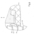
- Fig. 8 shows the already by means of Fig. 5 illustrated cone 32 and the radially aligned abutment surfaces 34 which are arranged along the strand peripheral surface as a latching system 26 around a core strand 28 around. Against one of the stop surfaces 34 engages an edge 40 of the second tension or tie rod 8 a. The tie rod 8 is pressed by the outwardly pressing cardboard wall 5 along the arrow x against the stop surface 40, which holds the tie rod 8 against axial continued slipping.
- the tension or tie rod 8 can be easily removed from the locking portion 30.
- the tie rod 8 is withdrawn laterally beyond the pressure point of the waist 16.
- the clamping system 2 are removed from the cardboard interior by the clamping system 2 is taken on the first tie rod 4 and withdrawn from the holes in the cardboard or side walls 3, 5.
- the invention provides for the stabilization of cardboard walls 3, 5, a clamping system 2 for clamping of opposite cardboard walls 3, 5 inside a carton before 1, comprising a first clamping anchor 4, a tensioning strand 6 and a second tensioning anchor 4, wherein the tensioning strand 6 in tensioned state, the first clamping anchor 4 opposite tip 10 and between the tip 10 and the first clamping anchor 4, the second clamping anchor 4 releasably lockable on the tensioning strand 6 while maintaining the tension.
- the clamping system 2 allows easy handling with cardboard walls 3, 5 different wall thicknesses and thus for internal and external dimensions.
Landscapes
- Engineering & Computer Science (AREA)
- General Engineering & Computer Science (AREA)
- Mechanical Engineering (AREA)
- Making Paper Articles (AREA)
- Cartons (AREA)
Description
- Die Erfindung betrifft ein Spannsystem nach dem Oberbegriff des Anspruches 1.
- Ein Spannsystem der eingangs genannten Art ist der Schrift zu
US 4,617,702 zu entnehmen. Diese offenbart einen streifenartigen Flachstrang mit rechteckigem Rinnenquerschnitt aus polymerem Werkstoff; in den Rinnenquerschnitt ist ein Zahngrund eingeformt, dessen die Längsachse querende Zahnstreifen sich zwischen den Rinnenlängsrändern erstrecken. Zudem ist einends ein Tellerkopf angeformt; das andere Strangende ist zungenartig ausgebildet. Auf dieses freie Ende kann ein zweiter Tellerkopf mit entsprechend gezahntem mittigem Durchbruch aufgeschoben und durch die beiden erwähnten, ineinander greifenden Zahnkomponenten festgelegt werden. Diese Vorrichtung dient der Verbindung einander zwischen den Tellerköpfen zuzuordnender Gegenstände. - Ebenfalls erfasst die
WO 01/62113 A1 - Die Verbindung eines Ölkühlkörpers mit einem Radiator, die flächig aneinander liegen, zeigt die
US 3,938,587 . Ein Spannstrang mit einends angeformtem Tellerkopf durchsetzt Kanäle beider Elemente, und das aus dem Ölkühlkörper ragende freie Ende des mit Querrillen versehenen Spannstranges nimmt einen zweiten Tellerkopf mit mittigem Durchbruch auf; in diesen ragen Blattfedern, die in Fixierstellung in eine der Querrillen eingreifen. - Im Transportwesen ist es üblich, die Kosten zum Transport von Transportgütern nach einer von den Transportgütern beanspruchten Grundfläche anzusetzen. Um Kosten beim Transport möglichst gering zu halten, ist es wünschenswert, Transportgüter möglichst hoch zu stapeln. Um dies zu erreichen, ist je nach Gewicht der anfallenden Transportgüter ein entsprechend stabiler Karton vorzusehen. Oftmals handelt es sich jedoch um Transportgüter, die, beispielsweise als leichtes Schüttgut, nur ein geringes Gewicht aufweisen. Der Boden eines Kartons ist im Vergleich zu den Seitenwänden relativ stabil. Die obengenannte Verwendung eines stabilen Kartons, d.h., insbesondere mit stabilen Seitenwänden, auch für leichtere Transportgüter ist deshalb ineffektiv und kostenaufwändig.
- Dieses Problem kann durch die Verwendung möglichst leichter Kartons gelöst werden. Diese erweisen sich beim Stapeln jedoch oft als nicht formstabil. Bei einer vollen Befüllung derselben beulen die leichten Kartons seitlich aus und lassen sich insbesondere nicht mehr effektiv nebeneinander stapeln.
- Wünschenswert wäre eine Vorrichtung einfacher Handhabbarkeit zur Stabilisierung eines Behälters aus Kartonwerkstoff.
- An dieser Stelle setzt die Erfindung an, deren Aufgabe es ist, ein Spannsystem zum Abspannen von gegenüberliegenden Kartonwänden in einem Karton anzugeben, das sich als gleichermaßen effektiv und sicher anwendbar erweist.
- Zur Lösung der Aufgabe ist zum Abspannen von gegenüberliegenden Kartonwänden in einem Karton der zweite Spannanker im gespannten Zustand des Spannsystems unter Beibehaltung der Spannung von einer Seite her auf dem Spannstrang arretierbar, und dieser weist vor dem als Spitze ausgebildeten freien Ende einen Arretierbereich auf; der zweite Spannanker ist im Arretierbereich lösbar am Spannstrang befestigbar.
- Erfindungsgemäß ist ein Spannanker in Form eines Spanntellers gebildet. Dies gewährleistet die flächige Auflage eines Spannankers und die Verteilung der Spannkraft auf eine möglichst große Fläche. Damit ist eine Arretierung des Spannankers auch bei besonders dünnwandigen Kartonwänden möglich.
- Die Erfindung geht von der Überlegung aus, dass das Spannsystem für einen flüssigen Bewegungsablauf zum Abspannen von gegenüberliegenden Kartonwänden geeignet sein sollte. Mit anderen Worten, die Erfindung hat erkannt, dass beim Anbringen des Spannsystems möglichst effektiv eine Verankerung des Spannsystems erfolgen sollte, das Durchbohren der Kartonwände erfolgen sollte und das Festlegen der Spannung ebenfalls möglichst einfach realisierbar sein sollte - dies möglichst in einer Bewegung. Gemäß dieser Überlegung ist bei dem Spannsystem entsprechend dem Konzept der Erfindung eine dem ersten Spannanker gegenüberliegende Spitze vorgesehen. Diese kann in besonders einfacher Weise genutzt werden, um mit der von Hand geführten Spitze ein Loch in eine erste Kartonwand zu bohren und gleichzeitig, ähnlich wie bei einer Nadel, die Spitze mit dem daran angeformten Spannstrang, ähnlich eines Fadens, durch das Loch hindurch zur gegenüberliegenden Kartonwand zu führen. Gemäß der Überlegung der Erfindung wird die Spitze dort wiederum besonders einfach genutzt, um ein zweites Loch, dieses Mal in der gegenüberliegenden Kartonwand, zu bohren, die Spitze hindurchzuführen und auf der äußeren Seite der Kartonwand das Spannsystems so lange zu ziehen, bis der erste Spannanker an der ersten Kartonwand festgelegt ist. Gemäß dem Konzept der vorliegenden Erfindung kann nunmehr zwischen der Spitze und dem ersten Spannanker der zweite Spannanker lösbar auf dem Spannstrang unter Beibehaltung der Spannung, gegebenenfalls indem der Anwender die gegenüberliegende Kartonwand zurückdrückt, arretiert werden. Zweckmäßigerweise wird der zweite Spannanker auf der Außenseite des Kartons auf dem Spannstrang arretiert.
- Das Spannsystem gemäß dem Konzept der Erfindung kommt somit ohne aufwändige Maßnahmen wie das Bilden von Schraub- oder Ösenverbindungen oder Knoten oder Schraub-/Mutterverbindungen oder ähnlichem aus, sondern nutzt im Wesentlichen bereits das Hindurchführen des Spannstranges von der ersten Kartonwand zur gegenüberliegenden Kartonwand, um das Spannsystem zu verankern, unter Spannung zu setzen und zu arretieren.
- Die Erfindung macht es möglich, anstatt schwerer Kartons vermehrt leichte Kartons zu nutzen und damit anfallende Transportkosten, insbesondere für vergleichsweise geringgewichtige Transportgüter, zu senken. In der Regel erweist sich auch bei dünnen Kartons ein Kartonboden als ausreichend tragfähig.
- Weiterbildungen der Erfindung sind den Unteransprüchen zu entnehmen, auch geben im Einzelnen vorteilhafte Möglichkeiten an das Konzept der Erfindung im Rahmen der Aufgabenstellung und hinsichtlich weiterer Vorteile zu realisieren
- Vorzugsweise ist der Spitze ein Griffbereich, insbesondere ein Griffbereich mit Taille vorgelagert. Der Spannstrang ist dadurch besonders einfach handhabbar.
- Zweckmäßigerweise weist der Spannstrang vor der Spitze, insbesondere vor dem Griffbereich einen Arretierbereich auf, in dem der zweite Spannanker lösbar am Spannstrang befestigbar ist. Der Arretierbereich ermöglicht vorteilhaft das Befestigen des zweiten Spannankers ohne Knoten oder Schraub-/Mutterverbindungen.
- Vorzugsweise weist der zweite Spannanker, insbesondere Spannteller, einen radial verlaufenden Schlitz auf, der in einem mittigen Loch mündet, wobei die Mündung in Form einer Taille gebildet ist. Dies hat den Vorteil, dass der zweite Spannanker mit dem radial verlaufenden Schlitz einfach von der Seite her auf den Spannstrang gesteckt werden kann.
- Vorzugsweise weist der Arretierbereich des Spannstranges ein Rastsystem auf. Insbesondere kann dies in Form einer gezahnten Strangumfangsfläche gebildet sein. In diesem Zusammenhang hat es sich als besonders vorteilhaft erwiesen, dass die Strangumfangsfläche um einen Kernstrang herum angeordnete, gegen eine Spannrichtung kegelig abgestützte, radial ausgerichtete Anschlagflächen aufweist. Ein solches Rastsystem lässt sich besonders einfach durch plastische Formgebungsverfahren im Bereich der Kunststoffindustrie herstellen.
- Vorzugsweise weist eine vorgenannte Taille des zweiten Spannankers einen geringfügig kleineren Durchmesser als der Kernstrang auf. Nach Aufschieben des zweiten Spannankers lässt sich dieser unter Überwindung eines Schwelldruckes mittig auf dem Spannstrang einrasten.
- Vorzugsweise ist der Spannstrang mit Spitze, Griffbereich, Arretierbereich und Rastsystem und dem ersten Spannanker einstückig gebildet. Das genannte Spannsystem lässt sich im Rahmen der Kunststoffindustrie somit besonders leicht als zweiteiliges. Set aus dem Spannstrang mit Spitze, Griffbereich, Arretierbereich, Rastsystem und ersten Spannanker einerseits sowie dem zweiten Spannanker andererseits zur Verfügung stellen.
- Vorzugsweise übersteigt der größte Durchmesser des Spannstranges einen Durchmesser eines durch die Spitze in einer Kartonwand erzeugbaren Loches nicht. Dies garantiert das möglichst reibungslose Durchführen des Spannstranges durch das von der Spitze erzeugte Loch.
- Die Erfindung führt auch auf einen Karton mit einem oder mehreren Spannsystemen der oben erläuterten Art.
- Ausführungsbeispiele der Erfindung werden nun nachfolgend anhand der Zeichnung beschrieben. Diese soll die Ausführungsbeispiele nicht notwendigerweise maßstäblich darstellen, vielmehr ist die Zeichnung, wo zu zur Erläuterung dienlich, in schematisierter und/oder leicht verzerrter Form ausgeführt. Im Hinblick auf Ergänzungen der aus der Zeichnung unmittelbar erkennbaren Lehren wird auf den einschlägigen Stand der Technik verwiesen. Dabei ist zu berücksichtigen, dass vielfältige Modifikationen und Änderungen betreffend die Form und das Detail einer Ausführungsform vorgenommen werden können, ohne von der allgemeinen Idee der Erfindung abzuweichen.
- Die Figuren der Zeichnung zeigen im Einzelnen in:
- Fig. 1:
- eine perspektivische Ansicht eines Kartons und dessen Innenraum mit einem Spannsystem gemäß einer bevorzugten Ausführungsform der Erfindung;
- Fig. 2:
- eine Ansicht von oben auf den Karton und dessen Innenraum gemäß
Fig. 1 ; - Fig. 3:
- die Seitenansicht (A) auf den Karton mit einem ersten Spannanker gemäß der bevorzugten Ausführungsform der Erfindung und die Draufsicht (B) auf den ersten Spannanker;
- Fig. 4:
- eine Seitenansicht (A) auf den Karton mit einem zweiten Spannanker gemäß der bevorzugten Ausführungsform der Erfindung und die Draufsicht (B) auf den zweiten Spannanker;
- Fig. 5:
- eine perspektivische Ansicht des Griffbereiches, eines Teiles des Arretierbereiches und des zweiten Spannankers in arretiertem Zustand beim Spannsystem gemäß der bevorzugten Ausführungsform der Erfindung;
- Fig. 6:
- die Teile des Spannsystems der
Fig. 5 nach Abtrennen eines Griffbereiches und eines überstehenden Arretierungsbereiches bei einem Spannsystem gemäß der bevorzugten Ausführungsform; - Fig. 7:
- eine Draufsicht auf das gesamte Spannsystem, wie es im angebrachten Zustand bei einem Karton der
Fig. 1 gezeigt ist; - Fig. 8:
- die Vergrößerung des Ausschnittes C von
Fig. 7 . -
Fig. 1 zeigt einen Karton 1 mit einem Spannsystem 2, das in Bezug auf die folgendenFig. 2 bis Fig. 8 näher erläutert ist. Dieses Spannsystem 2 zum Abspannen der gegenüberliegenden Kartonwände 3, 5 des Kartons 1 weist gemäßFig. 2 einen ersten Spannanker 4, einen Spannstrang 6 und einen zweiten Spannanker 8 auf. Der Spannstrang 6 ist mit einer im angespannten Zustand einer dem ersten Spannanker 4 gegenüberliegenden Spitze 10 versehen, zwischen der und dem ersten Spannanker 4 der zweite Spannanker 8 lösbar auf dem Spannstrang 6 unter Beibehaltung der Spannung arretierbar ist. Die Spitze 10 mit Griffbereich 22 und einem Teil 30' eines Arretierbereichs 30 ist danach einfach entfernbar. -
Fig. 3 zeigt als Seiten- oder Außenansicht (A) des Kartons 1 die Kartonseitenwand 3. Dabei ist von außen der als flacher Spannteller ausgebildete erste Spannanker 4 zu erkennen, der in Ansicht (B) vergrößert dargestellt ist. Der erste Spannanker 4 weist neben der flachen tellerförmigen Ausformung einen mittigen Ansatz auf, an den der Spannstrang 6 angeformt ist. -
Fig. 4 zeigt den Karton 1 in einer Seitenansicht (A), wobei die Kartonwand 5 von außen gezeigt ist. Dabei ist der zweite Spannanker 8 eingezeichnet, der ebenfalls in Form eines Spanntellers ausgebildet ist. Der zweite tellerförmige Spannanker 8 ist in Ansicht (B) vonFig. 4 näher dargestellt und weist einen radial verlaufenden Schlitz 12 auf. Der Schlitz 12 mündet einerseits in einer einem mittigen Loch 14 vorgelagerten Taille 16 und weist andererseits eine zum Umfang 18 des Spannankers 8 hin sich öffnende Aufweitung 20 auf. - Wie anhand
Fig. 5 ersichtlich, wird das Spannsystem 2 mit der Spitze 10 zuvor an einer beliebigen Stelle, wie sie inFig. 3 , Ansicht (A), zu sehen ist, durch die Kartonwand 3 des Kartons 1 in Spannrichtung gezogen. Dadurch werden die zwei gegenüberliegenden Kartonwände 3, 5 des Kartons 1 in stabilisierender Weise mit dem Spannsystem 2 gegeneinander gezogen. Um ein entsprechendes Loch in der Kartonwand 3 zu erzeugen, ist die Spitze 10 in noch zu erläuternder Weise ausgeführt. Das Spannsystem 2 wird durch das Loch gezogen, bis der Spannanker 4 in Form eines Spanntellers gegen die Kartonwand 3 - wie inFig. 2 zu sehen - anschlägt. Das auf eine bestimmte Breite eines Kartons 1 ausgelegte Spannsystem 2 wird dazu auch mit der Spitze 10 durch die zweite Kartonwand 5 gestoßen. Danach wird, gegebenenfalls unter Druck auf die Kartonwand 5, der Spannstrang 6 angezogen, um die Kartonwände 3 und 5 gegeneinander zu ziehen. Ist die nötige Spannung erreicht, wird der zweite Spannanker 8 an geeigneter Stelle des Spannstranges 6 mit der Aufweitung 20 und dem dieser folgenden Schlitz 12 über den Spannstrang 6 geschoben und schließlich mit dem mittigen Loch 14 auf dem Spannstrang 6 arretiert. Dabei wird der zweite Spannanker 8 über den Widerstand der Taille 16 hinaus auf den Spannstrang 6 geschoben und ist so gegen ein seitliches Lösen gesichert. - Anhand der
Fig. 5 bis Fig. 8 wird im Einzelnen die Arretierung des zweiten Spannankers 8 auf dem Spannsystem 2 erläutert. -
Fig. 5 zeigt das überstehende Ende des Spannsystems 2 außerhalb des Kartons 1 jenseits der Kartonwand 5; es sind die Spitze 10 des Spannsystems 2, der der Spitze 10 vorgelagerte Griffbereich 22 mit Taille 24 sowie der dem Griff vorgelagerte Teil 30' des Arretierbereiches 30 gezeigt, zudem in perspektivischer Darstellung der mit der Aufweitung 20 zuvor und dem nachfolgenden Schlitz 12 auf den Arretierbereich 30 geschobene zweite Spannanker 8 in Form eines Spanntellers. Der zweite Spannanker 8 ist aufgrund der Taille 16 gegen ein seitliches Lösen vom Arretierbereich 30 gesichert. Die Taille 16 weist dazu einen geringförmig geringeren Durchmesser als der Kerndurchmesser d des Arretierbereiches 30' auf. Im übrigen ist der Arretierbereich 30' dadurch gebildet, dass, wie inFig. 8 im Detail gezeigt, die Strangumfangsfläche um einen Kernstrang 28 herum angeordnete, mit Kegeln 32 abgestützte radial ausgerichtete Anschlagflächen 34 aufweist. Das mittige Loch 14 des zweiten Spannankers 8 weist einen Durchmesser auf, der geringer als der Durchmesser der Anschlagflächen 34 ist und somit gegen ein axiales Verschieben aufgrund der gegen den zweiten Spannanker 8 drückenden Kartonwand 5 gehalten ist. -
Fig. 7 zeigt in Draufsicht den Endzustand des am Karton 1 angebrachten Spannsystems 2 unmittelbar nach Arretierung des zweiten Spannankers 8. Der überstehende Arretierbereich 30' sowie der Griffbereich 22 mit Spitze 10 wird, wie inFig. 6 gezeigt, einfach an geeigneter Stelle hinter dem zweiten Spannanker 8 abgebrochen. Da zwischen den Kegeln 32 und den Anschlagflächen 34 der Kerndurchmesser am geringsten ist und auf diese Weise praktisch Sollbruchstellen definiert sind, ist dies problemlos möglich. - Bei der in
Fig. 7 gezeigten Ausführungsform tragen die als Teller ausgebildeten Spannanker 4, 8 kaum auf der Außenseite einer Kartonwand 3, 5 auf, so dass ein Karton 1 ohne Probleme eng benachbart zu anderen Kartons gestapelt werden kann. Durch das Spannsystem 2 sind Ausbeulungen der Kartonwände 3, 5 vermieden. Obwohl vorliegend ein dünnwandiger Karton 1 verwendet wird, kann er mit vergleichsweise schwerem Transportgut voll befüllt und/oder mehrfach gestapelt werden. Das Spannsystem 2 stabilisiert die Seitenwände 3, 5 in ausreichender Weise. -
Fig. 8 zeigt die bereits anhand vonFig. 5 erläuterten Kegel 32 und die radial ausgerichteten Anschlagflächen 34, die entlang der Strangumfangsfläche als Rastsystem 26 um einen Kernstrang 28 herum angeordnet sind. Gegen eine der Anschlagflächen 34 rastet eine Kante 40 des zweiten Spann-oder Zugankers 8 ein. Der Zuganker 8 wird durch die nach außen drückende Kartonwand 5 entlang des Pfeiles x gegen die Anschlagfläche 40 gedrückt, welche den Zuganker 8 gegen ein axiales Weiterrutschen hält. - Zum Lösen des Spannsystems 2 kann der Spann- oder Zuganker 8 leicht vom Arretierbereich 30 abgezogen werden. Dazu wird der Zuganker 8 über den Druckpunkt der Taille 16 hinweg seitlich abgezogen. Danach kann, wie aus
Fig. 1 oderFig. 7 ersichtlich ist, das Spannsystem 2 aus dem Kartoninnenraum entfernt werden, indem das Spannsystem 2 am ersten Zuganker 4 ergriffen und aus den Löchern in den Karton- oder Seitenwänden 3, 5 abgezogen wird. - Zusammenfassend sieht die Erfindung zur Stabilisierung von Kartonwänden 3, 5 ein Spannsystem 2 zum Abspannen von gegenüberliegenden Kartonwänden 3, 5 im Inneren eines Kartons 1 vor, das einen ersten Spannanker 4, einen Spannstrang 6 und einen zweiten Spannanker 4 aufweist, wobei der Spannstrang 6 im gespannten Zustand eine dem ersten Spannanker 4 gegenüberliegende Spitze 10 aufweist und zwischen der Spitze 10 und dem ersten Spannanker 4 der zweite Spannanker 4 lösbar auf dem Spannstrang 6 unter Beibehaltung der Spannung arretierbar ist. Das Spannsystem 2 ermöglicht eine problemlose Handhabung bei Kartonwänden 3, 5 unterschiedlicher Wanddicken und somit für Innen - und Außenmasse.
Claims (10)
- Spannsystem (2), das einen Spannstrang (6) mit einem endwärtigen festliegenden tellerartigen ersten Spannanker (4) sowie einem gegenüberliegenden freien Ende aufweist, wobei zwischen diesem und dem ersten Spannanker ein zweiter Spannanker (8) lösbar auf dem Spannstrang arretierbar ist,
dadurch gekennzeichnet,
dass zum Abspannen von gegenüberliegenden Kartonwänden (3, 5) in einem Karton (1) der zweite Spannanker (8) im gespannten Zustand des Spannsystems (2) unter Beibehaltung der Spannung von einer Seite her auf dem Spannstrang (6) arretierbar ist und dieser vor dem als Spitze (10) ausgebildeten freien Ende einen Arretierbereich (30, 30') aufweist und der zweite Spannanker im Arretierbereich lösbar am Spannstrang (6) befestigbar ist. - Spannsystem nach Anspruch 1, dadurch gekennzeichnet, dass der zweite Spannanker (8) einen radial verlaufenden Schlitz (12) aufweist, der in einem mittigen Loch (14) mündet, wobei die Mündung in Form einer Taille (16) gebildet ist.
- Spannsystem nach Anspruch 1 oder 2, dadurch gekennzeichnet, dass der Arretierbereich (30, 30') ein Rastsystem (26) aufweist.
- Spannsystem nach Anspruch 3, dadurch gekennzeichnet, dass das Rastsystem (26) in Form einer gezahnten Strang-Umfangsfläche gebildet ist.
- Spannsystem nach Anspruch 4, dadurch gekennzeichnet, dass die Strang-Umfangsfläche um einen Kernstrang (28) herum angeordnete gegen eine Spannrichtung (x) durch Kegel (32) abgestützte, radial ausgerichtete Anschlagflächen (34) aufweist.
- Spannsystem nach einem der Ansprüche 1 bis 5, dadurch gekennzeichnet, dass eine Taille (16) des zweiten Spannankers (8) einen geringfügig kleineren Durchmesser als der Kernstrang (28) aufweist.
- Spannsystem nach einem der Ansprüche 1 bis 6, dadurch gekennzeichnet, dass vor der Spitze (10) ein Griffbereich (22), insbesondere ein Griffbereich mit Taille (24) und vor diesem der Arretierbereich (30, 30') geringeren Durchmessers (d) angeordnet ist.
- Spannsystem nach einem der Ansprüche 1 bis 7, dadurch gekennzeichnet, dass der Spannstrang (6) mit Spitze (10), Griffbereich (22), Arretierbereich (30, 30') und Rastsystem (26) und dem ersten Spannanker (4) einstückig gebildet ist.
- Spannsystem nach einem der Ansprüche 1 bis 8, dadurch gekennzeichnet, dass der größte Durchmesser des Spannstrangs (6) einen Durchmesser eines durch die Spitze (10) in einer Kartonwand (3, 5) erzeugbaren Loches (14) nicht übersteigt.
- Karton (1) mit einem Spannsystem (2) nach einem der vorhergehenden Ansprüche.
Applications Claiming Priority (1)
| Application Number | Priority Date | Filing Date | Title |
|---|---|---|---|
| DE202005019632U DE202005019632U1 (de) | 2005-12-13 | 2005-12-13 | Spannsystem zum Abspannen von gegenüberliegenden Kartonwänden im Inneren eines Kartons |
Publications (2)
| Publication Number | Publication Date |
|---|---|
| EP1798158A1 EP1798158A1 (de) | 2007-06-20 |
| EP1798158B1 true EP1798158B1 (de) | 2009-01-21 |
Family
ID=36202315
Family Applications (1)
| Application Number | Title | Priority Date | Filing Date |
|---|---|---|---|
| EP06007070A Expired - Lifetime EP1798158B1 (de) | 2005-12-13 | 2006-04-03 | Spannsystem zum Abspannen von gegenüberliegenden Kartonwänden im Inneren eines Kartons |
Country Status (3)
| Country | Link |
|---|---|
| EP (1) | EP1798158B1 (de) |
| AT (1) | ATE421467T1 (de) |
| DE (2) | DE202005019632U1 (de) |
Families Citing this family (1)
| Publication number | Priority date | Publication date | Assignee | Title |
|---|---|---|---|---|
| EP4201831B1 (de) * | 2021-12-20 | 2025-03-19 | InnoDo AG | Spanneinheit und vorratseinheit mit wenigstens einer spanneinheit |
Family Cites Families (4)
| Publication number | Priority date | Publication date | Assignee | Title |
|---|---|---|---|---|
| FR1248748A (fr) * | 1960-02-05 | 1960-12-23 | Dispositif pour le ligaturage de paquets ou autres objets | |
| US3938587A (en) * | 1975-01-06 | 1976-02-17 | Hayden Trans-Cooler, Inc. | Cooler fastening system |
| US4617702A (en) * | 1985-01-22 | 1986-10-21 | Diederich Paul W Jun | Tie mount |
| US6347435B1 (en) * | 2000-02-25 | 2002-02-19 | Avery Dennison Corporation | Rivet tie for coupling together two or more objects |
-
2005
- 2005-12-13 DE DE202005019632U patent/DE202005019632U1/de not_active Expired - Lifetime
-
2006
- 2006-04-03 AT AT06007070T patent/ATE421467T1/de not_active IP Right Cessation
- 2006-04-03 DE DE502006002704T patent/DE502006002704D1/de not_active Expired - Lifetime
- 2006-04-03 EP EP06007070A patent/EP1798158B1/de not_active Expired - Lifetime
Also Published As
| Publication number | Publication date |
|---|---|
| DE202005019632U1 (de) | 2006-03-30 |
| ATE421467T1 (de) | 2009-02-15 |
| DE502006002704D1 (de) | 2009-03-12 |
| EP1798158A1 (de) | 2007-06-20 |
Similar Documents
| Publication | Publication Date | Title |
|---|---|---|
| DE60300968T2 (de) | Niet mit einem elastischen Fuss | |
| DE112004001734B4 (de) | Vorrichtung zum Verbinden zweier Bauteile in einer Abstandsstellung zueinander | |
| EP1661523B1 (de) | Einsatz für ein Klemmelement, Klemmelement mit einem solchen Einsatz und daraus gebildete Gelenkverbindung | |
| DE69802454T2 (de) | Anker mit Gewinde | |
| DE4330052A1 (de) | Verschlußverfahren und Verschlußvorrichtung | |
| EP0808283B1 (de) | Verpackung mit unterlegscheiben | |
| EP3660339B1 (de) | Toleranzausgleichsvorrichtung | |
| DE3517620C2 (de) | Plastik-Clip | |
| EP2232087B1 (de) | Verbindungseinrichtung und verfahren zum erstellen einer schraubverbindung | |
| EP0628734B1 (de) | Befestigungselement zum lösbaren Verbinden eines Mehrkantrohres, vorzugsweise eines Vierkantrohres | |
| DE2546831C2 (de) | Schraubmutter | |
| WO2010089065A1 (de) | Klemmeinrichtung | |
| EP3865716A1 (de) | Klammer zum lösbaren verbinden von bauelementen | |
| EP1156258A1 (de) | Federbandschellenblock | |
| EP1798158A1 (de) | Spannsystem zum Abspannen von gegenüberliegenden Kartonwänden im Inneren eines Kartons | |
| DE102010024419A1 (de) | Verfahren zur Befestigung von einem ersten Bauteil an einem zweiten Bauteil eines Fahrzeugs sowie entsprechende Befestigungsvorrichtung | |
| EP3264398B1 (de) | Aufsteckvorrichtung und -verfahren | |
| DE202008008250U1 (de) | Eckverbinder | |
| DE202006015624U1 (de) | Behältnis mit begrenzt flexiblen Wänden und Spannstrang für diese | |
| DE29603389U1 (de) | Schnellverschluß | |
| DE102022107208B3 (de) | Spanneinheit und Vorratseinheit mit wenigstens einer Spanneinheit | |
| DE3825084C2 (de) | ||
| EP3609719B1 (de) | Büroklammernsystem mit verbesserter haltekapazität | |
| EP4201831B1 (de) | Spanneinheit und vorratseinheit mit wenigstens einer spanneinheit | |
| DE3805232C2 (de) |
Legal Events
| Date | Code | Title | Description |
|---|---|---|---|
| PUAI | Public reference made under article 153(3) epc to a published international application that has entered the european phase |
Free format text: ORIGINAL CODE: 0009012 |
|
| AK | Designated contracting states |
Kind code of ref document: A1 Designated state(s): AT BE BG CH CY CZ DE DK EE ES FI FR GB GR HU IE IS IT LI LT LU LV MC NL PL PT RO SE SI SK TR |
|
| AX | Request for extension of the european patent |
Extension state: AL BA HR MK YU |
|
| 17P | Request for examination filed |
Effective date: 20070815 |
|
| 17Q | First examination report despatched |
Effective date: 20071001 |
|
| AKX | Designation fees paid |
Designated state(s): AT BE BG CH CY CZ DE DK EE ES FI FR GB GR HU IE IS IT LI LT LU LV MC NL PL PT RO SE SI SK TR |
|
| GRAP | Despatch of communication of intention to grant a patent |
Free format text: ORIGINAL CODE: EPIDOSNIGR1 |
|
| GRAS | Grant fee paid |
Free format text: ORIGINAL CODE: EPIDOSNIGR3 |
|
| GRAA | (expected) grant |
Free format text: ORIGINAL CODE: 0009210 |
|
| AK | Designated contracting states |
Kind code of ref document: B1 Designated state(s): AT BE BG CH CY CZ DE DK EE ES FI FR GB GR HU IE IS IT LI LT LU LV MC NL PL PT RO SE SI SK TR |
|
| REG | Reference to a national code |
Ref country code: GB Ref legal event code: FG4D Free format text: NOT ENGLISH |
|
| REG | Reference to a national code |
Ref country code: CH Ref legal event code: EP |
|
| REG | Reference to a national code |
Ref country code: IE Ref legal event code: FG4D Free format text: LANGUAGE OF EP DOCUMENT: GERMAN |
|
| REF | Corresponds to: |
Ref document number: 502006002704 Country of ref document: DE Date of ref document: 20090312 Kind code of ref document: P |
|
| REG | Reference to a national code |
Ref country code: CH Ref legal event code: NV Representative=s name: BODENSEEPATENT HIEBSCH BEHRMANN WAGNER |
|
| PG25 | Lapsed in a contracting state [announced via postgrant information from national office to epo] |
Ref country code: NL Free format text: LAPSE BECAUSE OF FAILURE TO SUBMIT A TRANSLATION OF THE DESCRIPTION OR TO PAY THE FEE WITHIN THE PRESCRIBED TIME-LIMIT Effective date: 20090121 |
|
| NLV1 | Nl: lapsed or annulled due to failure to fulfill the requirements of art. 29p and 29m of the patents act | ||
| PG25 | Lapsed in a contracting state [announced via postgrant information from national office to epo] |
Ref country code: SI Free format text: LAPSE BECAUSE OF FAILURE TO SUBMIT A TRANSLATION OF THE DESCRIPTION OR TO PAY THE FEE WITHIN THE PRESCRIBED TIME-LIMIT Effective date: 20090121 Ref country code: LT Free format text: LAPSE BECAUSE OF FAILURE TO SUBMIT A TRANSLATION OF THE DESCRIPTION OR TO PAY THE FEE WITHIN THE PRESCRIBED TIME-LIMIT Effective date: 20090121 Ref country code: FI Free format text: LAPSE BECAUSE OF FAILURE TO SUBMIT A TRANSLATION OF THE DESCRIPTION OR TO PAY THE FEE WITHIN THE PRESCRIBED TIME-LIMIT Effective date: 20090121 Ref country code: ES Free format text: LAPSE BECAUSE OF FAILURE TO SUBMIT A TRANSLATION OF THE DESCRIPTION OR TO PAY THE FEE WITHIN THE PRESCRIBED TIME-LIMIT Effective date: 20090502 |
|
| REG | Reference to a national code |
Ref country code: IE Ref legal event code: FD4D |
|
| PG25 | Lapsed in a contracting state [announced via postgrant information from national office to epo] |
Ref country code: LV Free format text: LAPSE BECAUSE OF FAILURE TO SUBMIT A TRANSLATION OF THE DESCRIPTION OR TO PAY THE FEE WITHIN THE PRESCRIBED TIME-LIMIT Effective date: 20090121 Ref country code: SE Free format text: LAPSE BECAUSE OF FAILURE TO SUBMIT A TRANSLATION OF THE DESCRIPTION OR TO PAY THE FEE WITHIN THE PRESCRIBED TIME-LIMIT Effective date: 20090421 Ref country code: PT Free format text: LAPSE BECAUSE OF FAILURE TO SUBMIT A TRANSLATION OF THE DESCRIPTION OR TO PAY THE FEE WITHIN THE PRESCRIBED TIME-LIMIT Effective date: 20090622 Ref country code: PL Free format text: LAPSE BECAUSE OF FAILURE TO SUBMIT A TRANSLATION OF THE DESCRIPTION OR TO PAY THE FEE WITHIN THE PRESCRIBED TIME-LIMIT Effective date: 20090121 Ref country code: IS Free format text: LAPSE BECAUSE OF FAILURE TO SUBMIT A TRANSLATION OF THE DESCRIPTION OR TO PAY THE FEE WITHIN THE PRESCRIBED TIME-LIMIT Effective date: 20090521 |
|
| PG25 | Lapsed in a contracting state [announced via postgrant information from national office to epo] |
Ref country code: IE Free format text: LAPSE BECAUSE OF FAILURE TO SUBMIT A TRANSLATION OF THE DESCRIPTION OR TO PAY THE FEE WITHIN THE PRESCRIBED TIME-LIMIT Effective date: 20090121 Ref country code: CZ Free format text: LAPSE BECAUSE OF FAILURE TO SUBMIT A TRANSLATION OF THE DESCRIPTION OR TO PAY THE FEE WITHIN THE PRESCRIBED TIME-LIMIT Effective date: 20090121 Ref country code: DK Free format text: LAPSE BECAUSE OF FAILURE TO SUBMIT A TRANSLATION OF THE DESCRIPTION OR TO PAY THE FEE WITHIN THE PRESCRIBED TIME-LIMIT Effective date: 20090121 Ref country code: EE Free format text: LAPSE BECAUSE OF FAILURE TO SUBMIT A TRANSLATION OF THE DESCRIPTION OR TO PAY THE FEE WITHIN THE PRESCRIBED TIME-LIMIT Effective date: 20090121 |
|
| BERE | Be: lapsed |
Owner name: BACHLE, DIETER Effective date: 20090430 |
|
| PLBE | No opposition filed within time limit |
Free format text: ORIGINAL CODE: 0009261 |
|
| STAA | Information on the status of an ep patent application or granted ep patent |
Free format text: STATUS: NO OPPOSITION FILED WITHIN TIME LIMIT |
|
| PG25 | Lapsed in a contracting state [announced via postgrant information from national office to epo] |
Ref country code: SK Free format text: LAPSE BECAUSE OF FAILURE TO SUBMIT A TRANSLATION OF THE DESCRIPTION OR TO PAY THE FEE WITHIN THE PRESCRIBED TIME-LIMIT Effective date: 20090121 Ref country code: RO Free format text: LAPSE BECAUSE OF FAILURE TO SUBMIT A TRANSLATION OF THE DESCRIPTION OR TO PAY THE FEE WITHIN THE PRESCRIBED TIME-LIMIT Effective date: 20090121 |
|
| 26N | No opposition filed |
Effective date: 20091022 |
|
| REG | Reference to a national code |
Ref country code: FR Ref legal event code: ST Effective date: 20091231 |
|
| PG25 | Lapsed in a contracting state [announced via postgrant information from national office to epo] |
Ref country code: BG Free format text: LAPSE BECAUSE OF FAILURE TO SUBMIT A TRANSLATION OF THE DESCRIPTION OR TO PAY THE FEE WITHIN THE PRESCRIBED TIME-LIMIT Effective date: 20090421 |
|
| PG25 | Lapsed in a contracting state [announced via postgrant information from national office to epo] |
Ref country code: MC Free format text: LAPSE BECAUSE OF NON-PAYMENT OF DUE FEES Effective date: 20090430 Ref country code: FR Free format text: LAPSE BECAUSE OF NON-PAYMENT OF DUE FEES Effective date: 20091222 |
|
| PG25 | Lapsed in a contracting state [announced via postgrant information from national office to epo] |
Ref country code: BE Free format text: LAPSE BECAUSE OF NON-PAYMENT OF DUE FEES Effective date: 20090430 |
|
| PG25 | Lapsed in a contracting state [announced via postgrant information from national office to epo] |
Ref country code: AT Free format text: LAPSE BECAUSE OF NON-PAYMENT OF DUE FEES Effective date: 20090403 |
|
| PG25 | Lapsed in a contracting state [announced via postgrant information from national office to epo] |
Ref country code: GR Free format text: LAPSE BECAUSE OF FAILURE TO SUBMIT A TRANSLATION OF THE DESCRIPTION OR TO PAY THE FEE WITHIN THE PRESCRIBED TIME-LIMIT Effective date: 20090422 |
|
| GBPC | Gb: european patent ceased through non-payment of renewal fee |
Effective date: 20100403 |
|
| PG25 | Lapsed in a contracting state [announced via postgrant information from national office to epo] |
Ref country code: IT Free format text: LAPSE BECAUSE OF FAILURE TO SUBMIT A TRANSLATION OF THE DESCRIPTION OR TO PAY THE FEE WITHIN THE PRESCRIBED TIME-LIMIT Effective date: 20090121 Ref country code: GB Free format text: LAPSE BECAUSE OF NON-PAYMENT OF DUE FEES Effective date: 20100403 |
|
| PG25 | Lapsed in a contracting state [announced via postgrant information from national office to epo] |
Ref country code: LU Free format text: LAPSE BECAUSE OF NON-PAYMENT OF DUE FEES Effective date: 20090403 |
|
| PG25 | Lapsed in a contracting state [announced via postgrant information from national office to epo] |
Ref country code: HU Free format text: LAPSE BECAUSE OF FAILURE TO SUBMIT A TRANSLATION OF THE DESCRIPTION OR TO PAY THE FEE WITHIN THE PRESCRIBED TIME-LIMIT Effective date: 20090722 |
|
| PG25 | Lapsed in a contracting state [announced via postgrant information from national office to epo] |
Ref country code: TR Free format text: LAPSE BECAUSE OF FAILURE TO SUBMIT A TRANSLATION OF THE DESCRIPTION OR TO PAY THE FEE WITHIN THE PRESCRIBED TIME-LIMIT Effective date: 20090121 |
|
| PG25 | Lapsed in a contracting state [announced via postgrant information from national office to epo] |
Ref country code: CY Free format text: LAPSE BECAUSE OF FAILURE TO SUBMIT A TRANSLATION OF THE DESCRIPTION OR TO PAY THE FEE WITHIN THE PRESCRIBED TIME-LIMIT Effective date: 20090121 |
|
| REG | Reference to a national code |
Ref country code: CH Ref legal event code: PCOW Free format text: NEW ADDRESS: BACHSTRASSE 8, 8597 LANDSCHLACHT (CH) |
|
| REG | Reference to a national code |
Ref country code: CH Ref legal event code: PUE Owner name: INNODO AG, CH Free format text: FORMER OWNER: DIETER BAECHLE, CH |
|
| REG | Reference to a national code |
Ref country code: DE Ref legal event code: R082 Ref document number: 502006002704 Country of ref document: DE Representative=s name: PATENTANWAELTE BEHRMANN WAGNER PARTNERSCHAFTSG, DE Ref country code: DE Ref legal event code: R081 Ref document number: 502006002704 Country of ref document: DE Owner name: INNODO AG, CH Free format text: FORMER OWNER: BAECHLE, DIETER, UTTWIL, CH Ref country code: DE Ref legal event code: R082 Ref document number: 502006002704 Country of ref document: DE Representative=s name: PATENT- UND RECHTSANWAELTE BEHRMANN WAGNER PAR, DE |
|
| REG | Reference to a national code |
Ref country code: CH Ref legal event code: NV Representative=s name: BODENSEEPATENT PATENTANWAELTE BEHRMANN WAGNER , CH |
|
| REG | Reference to a national code |
Ref country code: DE Ref legal event code: R084 Ref document number: 502006002704 Country of ref document: DE |
|
| REG | Reference to a national code |
Ref country code: CH Ref legal event code: PFA Owner name: INNODO AG, CH Free format text: FORMER OWNER: INNODO AG, CH |
|
| PGFP | Annual fee paid to national office [announced via postgrant information from national office to epo] |
Ref country code: DE Payment date: 20240508 Year of fee payment: 19 |
|
| PGFP | Annual fee paid to national office [announced via postgrant information from national office to epo] |
Ref country code: CH Payment date: 20240501 Year of fee payment: 19 |
|
| REG | Reference to a national code |
Ref country code: DE Ref legal event code: R119 Ref document number: 502006002704 Country of ref document: DE |
|
| REG | Reference to a national code |
Ref country code: CH Ref legal event code: H13 Free format text: ST27 STATUS EVENT CODE: U-0-0-H10-H13 (AS PROVIDED BY THE NATIONAL OFFICE) Effective date: 20251125 |
|
| PG25 | Lapsed in a contracting state [announced via postgrant information from national office to epo] |
Ref country code: DE Free format text: LAPSE BECAUSE OF NON-PAYMENT OF DUE FEES Effective date: 20251104 |
|
| PG25 | Lapsed in a contracting state [announced via postgrant information from national office to epo] |
Ref country code: CH Free format text: LAPSE BECAUSE OF NON-PAYMENT OF DUE FEES Effective date: 20250430 |