EP1798040A1 - Ink-jet head and method of manufacturing the same - Google Patents
Ink-jet head and method of manufacturing the same Download PDFInfo
- Publication number
- EP1798040A1 EP1798040A1 EP06025691A EP06025691A EP1798040A1 EP 1798040 A1 EP1798040 A1 EP 1798040A1 EP 06025691 A EP06025691 A EP 06025691A EP 06025691 A EP06025691 A EP 06025691A EP 1798040 A1 EP1798040 A1 EP 1798040A1
- Authority
- EP
- European Patent Office
- Prior art keywords
- filter plate
- holes
- annular
- face
- ink
- Prior art date
- Legal status (The legal status is an assumption and is not a legal conclusion. Google has not performed a legal analysis and makes no representation as to the accuracy of the status listed.)
- Granted
Links
Images






Classifications
-
- B—PERFORMING OPERATIONS; TRANSPORTING
- B41—PRINTING; LINING MACHINES; TYPEWRITERS; STAMPS
- B41J—TYPEWRITERS; SELECTIVE PRINTING MECHANISMS, i.e. MECHANISMS PRINTING OTHERWISE THAN FROM A FORME; CORRECTION OF TYPOGRAPHICAL ERRORS
- B41J2/00—Typewriters or selective printing mechanisms characterised by the printing or marking process for which they are designed
- B41J2/005—Typewriters or selective printing mechanisms characterised by the printing or marking process for which they are designed characterised by bringing liquid or particles selectively into contact with a printing material
- B41J2/01—Ink jet
- B41J2/17—Ink jet characterised by ink handling
- B41J2/175—Ink supply systems ; Circuit parts therefor
- B41J2/17563—Ink filters
-
- B—PERFORMING OPERATIONS; TRANSPORTING
- B29—WORKING OF PLASTICS; WORKING OF SUBSTANCES IN A PLASTIC STATE IN GENERAL
- B29C—SHAPING OR JOINING OF PLASTICS; SHAPING OF MATERIAL IN A PLASTIC STATE, NOT OTHERWISE PROVIDED FOR; AFTER-TREATMENT OF THE SHAPED PRODUCTS, e.g. REPAIRING
- B29C65/00—Joining or sealing of preformed parts, e.g. welding of plastics materials; Apparatus therefor
- B29C65/56—Joining or sealing of preformed parts, e.g. welding of plastics materials; Apparatus therefor using mechanical means or mechanical connections, e.g. form-fits
- B29C65/60—Riveting or staking
- B29C65/606—Riveting or staking the rivets being integral with one of the parts to be joined, i.e. staking
-
- B—PERFORMING OPERATIONS; TRANSPORTING
- B29—WORKING OF PLASTICS; WORKING OF SUBSTANCES IN A PLASTIC STATE IN GENERAL
- B29C—SHAPING OR JOINING OF PLASTICS; SHAPING OF MATERIAL IN A PLASTIC STATE, NOT OTHERWISE PROVIDED FOR; AFTER-TREATMENT OF THE SHAPED PRODUCTS, e.g. REPAIRING
- B29C65/00—Joining or sealing of preformed parts, e.g. welding of plastics materials; Apparatus therefor
- B29C65/56—Joining or sealing of preformed parts, e.g. welding of plastics materials; Apparatus therefor using mechanical means or mechanical connections, e.g. form-fits
- B29C65/64—Joining a non-plastics element to a plastics element, e.g. by force
-
- B—PERFORMING OPERATIONS; TRANSPORTING
- B29—WORKING OF PLASTICS; WORKING OF SUBSTANCES IN A PLASTIC STATE IN GENERAL
- B29C—SHAPING OR JOINING OF PLASTICS; SHAPING OF MATERIAL IN A PLASTIC STATE, NOT OTHERWISE PROVIDED FOR; AFTER-TREATMENT OF THE SHAPED PRODUCTS, e.g. REPAIRING
- B29C66/00—General aspects of processes or apparatus for joining preformed parts
- B29C66/01—General aspects dealing with the joint area or with the area to be joined
- B29C66/05—Particular design of joint configurations
- B29C66/20—Particular design of joint configurations particular design of the joint lines, e.g. of the weld lines
- B29C66/21—Particular design of joint configurations particular design of the joint lines, e.g. of the weld lines said joint lines being formed by a single dot or dash or by several dots or dashes, i.e. spot joining or spot welding
-
- B—PERFORMING OPERATIONS; TRANSPORTING
- B29—WORKING OF PLASTICS; WORKING OF SUBSTANCES IN A PLASTIC STATE IN GENERAL
- B29C—SHAPING OR JOINING OF PLASTICS; SHAPING OF MATERIAL IN A PLASTIC STATE, NOT OTHERWISE PROVIDED FOR; AFTER-TREATMENT OF THE SHAPED PRODUCTS, e.g. REPAIRING
- B29C66/00—General aspects of processes or apparatus for joining preformed parts
- B29C66/01—General aspects dealing with the joint area or with the area to be joined
- B29C66/05—Particular design of joint configurations
- B29C66/302—Particular design of joint configurations the area to be joined comprising melt initiators
- B29C66/3022—Particular design of joint configurations the area to be joined comprising melt initiators said melt initiators being integral with at least one of the parts to be joined
- B29C66/30223—Particular design of joint configurations the area to be joined comprising melt initiators said melt initiators being integral with at least one of the parts to be joined said melt initiators being rib-like
-
- B—PERFORMING OPERATIONS; TRANSPORTING
- B29—WORKING OF PLASTICS; WORKING OF SUBSTANCES IN A PLASTIC STATE IN GENERAL
- B29C—SHAPING OR JOINING OF PLASTICS; SHAPING OF MATERIAL IN A PLASTIC STATE, NOT OTHERWISE PROVIDED FOR; AFTER-TREATMENT OF THE SHAPED PRODUCTS, e.g. REPAIRING
- B29C66/00—General aspects of processes or apparatus for joining preformed parts
- B29C66/50—General aspects of joining tubular articles; General aspects of joining long products, i.e. bars or profiled elements; General aspects of joining single elements to tubular articles, hollow articles or bars; General aspects of joining several hollow-preforms to form hollow or tubular articles
- B29C66/51—Joining tubular articles, profiled elements or bars; Joining single elements to tubular articles, hollow articles or bars; Joining several hollow-preforms to form hollow or tubular articles
- B29C66/53—Joining single elements to tubular articles, hollow articles or bars
- B29C66/534—Joining single elements to open ends of tubular or hollow articles or to the ends of bars
- B29C66/5346—Joining single elements to open ends of tubular or hollow articles or to the ends of bars said single elements being substantially flat
- B29C66/53461—Joining single elements to open ends of tubular or hollow articles or to the ends of bars said single elements being substantially flat joining substantially flat covers and/or substantially flat bottoms to open ends of container bodies
-
- B—PERFORMING OPERATIONS; TRANSPORTING
- B29—WORKING OF PLASTICS; WORKING OF SUBSTANCES IN A PLASTIC STATE IN GENERAL
- B29C—SHAPING OR JOINING OF PLASTICS; SHAPING OF MATERIAL IN A PLASTIC STATE, NOT OTHERWISE PROVIDED FOR; AFTER-TREATMENT OF THE SHAPED PRODUCTS, e.g. REPAIRING
- B29C66/00—General aspects of processes or apparatus for joining preformed parts
- B29C66/50—General aspects of joining tubular articles; General aspects of joining long products, i.e. bars or profiled elements; General aspects of joining single elements to tubular articles, hollow articles or bars; General aspects of joining several hollow-preforms to form hollow or tubular articles
- B29C66/61—Joining from or joining on the inside
-
- B—PERFORMING OPERATIONS; TRANSPORTING
- B29—WORKING OF PLASTICS; WORKING OF SUBSTANCES IN A PLASTIC STATE IN GENERAL
- B29C—SHAPING OR JOINING OF PLASTICS; SHAPING OF MATERIAL IN A PLASTIC STATE, NOT OTHERWISE PROVIDED FOR; AFTER-TREATMENT OF THE SHAPED PRODUCTS, e.g. REPAIRING
- B29C66/00—General aspects of processes or apparatus for joining preformed parts
- B29C66/70—General aspects of processes or apparatus for joining preformed parts characterised by the composition, physical properties or the structure of the material of the parts to be joined; Joining with non-plastics material
- B29C66/73—General aspects of processes or apparatus for joining preformed parts characterised by the composition, physical properties or the structure of the material of the parts to be joined; Joining with non-plastics material characterised by the intensive physical properties of the material of the parts to be joined, by the optical properties of the material of the parts to be joined, by the extensive physical properties of the parts to be joined, by the state of the material of the parts to be joined or by the material of the parts to be joined being a thermoplastic or a thermoset
- B29C66/731—General aspects of processes or apparatus for joining preformed parts characterised by the composition, physical properties or the structure of the material of the parts to be joined; Joining with non-plastics material characterised by the intensive physical properties of the material of the parts to be joined, by the optical properties of the material of the parts to be joined, by the extensive physical properties of the parts to be joined, by the state of the material of the parts to be joined or by the material of the parts to be joined being a thermoplastic or a thermoset characterised by the intensive physical properties of the material of the parts to be joined
- B29C66/7311—Thermal properties
- B29C66/73115—Melting point
-
- B—PERFORMING OPERATIONS; TRANSPORTING
- B29—WORKING OF PLASTICS; WORKING OF SUBSTANCES IN A PLASTIC STATE IN GENERAL
- B29C—SHAPING OR JOINING OF PLASTICS; SHAPING OF MATERIAL IN A PLASTIC STATE, NOT OTHERWISE PROVIDED FOR; AFTER-TREATMENT OF THE SHAPED PRODUCTS, e.g. REPAIRING
- B29C66/00—General aspects of processes or apparatus for joining preformed parts
- B29C66/70—General aspects of processes or apparatus for joining preformed parts characterised by the composition, physical properties or the structure of the material of the parts to be joined; Joining with non-plastics material
- B29C66/73—General aspects of processes or apparatus for joining preformed parts characterised by the composition, physical properties or the structure of the material of the parts to be joined; Joining with non-plastics material characterised by the intensive physical properties of the material of the parts to be joined, by the optical properties of the material of the parts to be joined, by the extensive physical properties of the parts to be joined, by the state of the material of the parts to be joined or by the material of the parts to be joined being a thermoplastic or a thermoset
- B29C66/731—General aspects of processes or apparatus for joining preformed parts characterised by the composition, physical properties or the structure of the material of the parts to be joined; Joining with non-plastics material characterised by the intensive physical properties of the material of the parts to be joined, by the optical properties of the material of the parts to be joined, by the extensive physical properties of the parts to be joined, by the state of the material of the parts to be joined or by the material of the parts to be joined being a thermoplastic or a thermoset characterised by the intensive physical properties of the material of the parts to be joined
- B29C66/7311—Thermal properties
- B29C66/73115—Melting point
- B29C66/73116—Melting point of different melting point, i.e. the melting point of one of the parts to be joined being different from the melting point of the other part
-
- B—PERFORMING OPERATIONS; TRANSPORTING
- B29—WORKING OF PLASTICS; WORKING OF SUBSTANCES IN A PLASTIC STATE IN GENERAL
- B29C—SHAPING OR JOINING OF PLASTICS; SHAPING OF MATERIAL IN A PLASTIC STATE, NOT OTHERWISE PROVIDED FOR; AFTER-TREATMENT OF THE SHAPED PRODUCTS, e.g. REPAIRING
- B29C66/00—General aspects of processes or apparatus for joining preformed parts
- B29C66/70—General aspects of processes or apparatus for joining preformed parts characterised by the composition, physical properties or the structure of the material of the parts to be joined; Joining with non-plastics material
- B29C66/74—Joining plastics material to non-plastics material
- B29C66/742—Joining plastics material to non-plastics material to metals or their alloys
-
- B—PERFORMING OPERATIONS; TRANSPORTING
- B29—WORKING OF PLASTICS; WORKING OF SUBSTANCES IN A PLASTIC STATE IN GENERAL
- B29C—SHAPING OR JOINING OF PLASTICS; SHAPING OF MATERIAL IN A PLASTIC STATE, NOT OTHERWISE PROVIDED FOR; AFTER-TREATMENT OF THE SHAPED PRODUCTS, e.g. REPAIRING
- B29C66/00—General aspects of processes or apparatus for joining preformed parts
- B29C66/80—General aspects of machine operations or constructions and parts thereof
- B29C66/83—General aspects of machine operations or constructions and parts thereof characterised by the movement of the joining or pressing tools
- B29C66/832—Reciprocating joining or pressing tools
- B29C66/8322—Joining or pressing tools reciprocating along one axis
-
- B—PERFORMING OPERATIONS; TRANSPORTING
- B41—PRINTING; LINING MACHINES; TYPEWRITERS; STAMPS
- B41J—TYPEWRITERS; SELECTIVE PRINTING MECHANISMS, i.e. MECHANISMS PRINTING OTHERWISE THAN FROM A FORME; CORRECTION OF TYPOGRAPHICAL ERRORS
- B41J2/00—Typewriters or selective printing mechanisms characterised by the printing or marking process for which they are designed
- B41J2/005—Typewriters or selective printing mechanisms characterised by the printing or marking process for which they are designed characterised by bringing liquid or particles selectively into contact with a printing material
- B41J2/01—Ink jet
- B41J2/135—Nozzles
- B41J2/14—Structure thereof only for on-demand ink jet heads
- B41J2/14201—Structure of print heads with piezoelectric elements
- B41J2/14209—Structure of print heads with piezoelectric elements of finger type, chamber walls consisting integrally of piezoelectric material
-
- B—PERFORMING OPERATIONS; TRANSPORTING
- B41—PRINTING; LINING MACHINES; TYPEWRITERS; STAMPS
- B41J—TYPEWRITERS; SELECTIVE PRINTING MECHANISMS, i.e. MECHANISMS PRINTING OTHERWISE THAN FROM A FORME; CORRECTION OF TYPOGRAPHICAL ERRORS
- B41J2/00—Typewriters or selective printing mechanisms characterised by the printing or marking process for which they are designed
- B41J2/005—Typewriters or selective printing mechanisms characterised by the printing or marking process for which they are designed characterised by bringing liquid or particles selectively into contact with a printing material
- B41J2/01—Ink jet
- B41J2/135—Nozzles
- B41J2/16—Production of nozzles
- B41J2/1607—Production of print heads with piezoelectric elements
- B41J2/1609—Production of print heads with piezoelectric elements of finger type, chamber walls consisting integrally of piezoelectric material
-
- B—PERFORMING OPERATIONS; TRANSPORTING
- B41—PRINTING; LINING MACHINES; TYPEWRITERS; STAMPS
- B41J—TYPEWRITERS; SELECTIVE PRINTING MECHANISMS, i.e. MECHANISMS PRINTING OTHERWISE THAN FROM A FORME; CORRECTION OF TYPOGRAPHICAL ERRORS
- B41J2/00—Typewriters or selective printing mechanisms characterised by the printing or marking process for which they are designed
- B41J2/005—Typewriters or selective printing mechanisms characterised by the printing or marking process for which they are designed characterised by bringing liquid or particles selectively into contact with a printing material
- B41J2/01—Ink jet
- B41J2/135—Nozzles
- B41J2/16—Production of nozzles
- B41J2/1621—Manufacturing processes
- B41J2/1623—Manufacturing processes bonding and adhesion
-
- B—PERFORMING OPERATIONS; TRANSPORTING
- B41—PRINTING; LINING MACHINES; TYPEWRITERS; STAMPS
- B41J—TYPEWRITERS; SELECTIVE PRINTING MECHANISMS, i.e. MECHANISMS PRINTING OTHERWISE THAN FROM A FORME; CORRECTION OF TYPOGRAPHICAL ERRORS
- B41J2/00—Typewriters or selective printing mechanisms characterised by the printing or marking process for which they are designed
- B41J2/005—Typewriters or selective printing mechanisms characterised by the printing or marking process for which they are designed characterised by bringing liquid or particles selectively into contact with a printing material
- B41J2/01—Ink jet
- B41J2/135—Nozzles
- B41J2/16—Production of nozzles
- B41J2/1621—Manufacturing processes
- B41J2/1626—Manufacturing processes etching
-
- B—PERFORMING OPERATIONS; TRANSPORTING
- B41—PRINTING; LINING MACHINES; TYPEWRITERS; STAMPS
- B41J—TYPEWRITERS; SELECTIVE PRINTING MECHANISMS, i.e. MECHANISMS PRINTING OTHERWISE THAN FROM A FORME; CORRECTION OF TYPOGRAPHICAL ERRORS
- B41J2/00—Typewriters or selective printing mechanisms characterised by the printing or marking process for which they are designed
- B41J2/005—Typewriters or selective printing mechanisms characterised by the printing or marking process for which they are designed characterised by bringing liquid or particles selectively into contact with a printing material
- B41J2/01—Ink jet
- B41J2/135—Nozzles
- B41J2/16—Production of nozzles
- B41J2/1621—Manufacturing processes
- B41J2/1631—Manufacturing processes photolithography
-
- B—PERFORMING OPERATIONS; TRANSPORTING
- B29—WORKING OF PLASTICS; WORKING OF SUBSTANCES IN A PLASTIC STATE IN GENERAL
- B29C—SHAPING OR JOINING OF PLASTICS; SHAPING OF MATERIAL IN A PLASTIC STATE, NOT OTHERWISE PROVIDED FOR; AFTER-TREATMENT OF THE SHAPED PRODUCTS, e.g. REPAIRING
- B29C66/00—General aspects of processes or apparatus for joining preformed parts
- B29C66/01—General aspects dealing with the joint area or with the area to be joined
- B29C66/05—Particular design of joint configurations
- B29C66/303—Particular design of joint configurations the joint involving an anchoring effect
- B29C66/3032—Particular design of joint configurations the joint involving an anchoring effect making use of protrusions or cavities belonging to at least one of the parts to be joined
- B29C66/30325—Particular design of joint configurations the joint involving an anchoring effect making use of protrusions or cavities belonging to at least one of the parts to be joined making use of cavities belonging to at least one of the parts to be joined
-
- B—PERFORMING OPERATIONS; TRANSPORTING
- B29—WORKING OF PLASTICS; WORKING OF SUBSTANCES IN A PLASTIC STATE IN GENERAL
- B29C—SHAPING OR JOINING OF PLASTICS; SHAPING OF MATERIAL IN A PLASTIC STATE, NOT OTHERWISE PROVIDED FOR; AFTER-TREATMENT OF THE SHAPED PRODUCTS, e.g. REPAIRING
- B29C66/00—General aspects of processes or apparatus for joining preformed parts
- B29C66/70—General aspects of processes or apparatus for joining preformed parts characterised by the composition, physical properties or the structure of the material of the parts to be joined; Joining with non-plastics material
- B29C66/71—General aspects of processes or apparatus for joining preformed parts characterised by the composition, physical properties or the structure of the material of the parts to be joined; Joining with non-plastics material characterised by the composition of the plastics material of the parts to be joined
-
- B—PERFORMING OPERATIONS; TRANSPORTING
- B29—WORKING OF PLASTICS; WORKING OF SUBSTANCES IN A PLASTIC STATE IN GENERAL
- B29K—INDEXING SCHEME ASSOCIATED WITH SUBCLASSES B29B, B29C OR B29D, RELATING TO MOULDING MATERIALS OR TO MATERIALS FOR MOULDS, REINFORCEMENTS, FILLERS OR PREFORMED PARTS, e.g. INSERTS
- B29K2023/00—Use of polyalkenes or derivatives thereof as moulding material
- B29K2023/10—Polymers of propylene
- B29K2023/12—PP, i.e. polypropylene
-
- B—PERFORMING OPERATIONS; TRANSPORTING
- B29—WORKING OF PLASTICS; WORKING OF SUBSTANCES IN A PLASTIC STATE IN GENERAL
- B29K—INDEXING SCHEME ASSOCIATED WITH SUBCLASSES B29B, B29C OR B29D, RELATING TO MOULDING MATERIALS OR TO MATERIALS FOR MOULDS, REINFORCEMENTS, FILLERS OR PREFORMED PARTS, e.g. INSERTS
- B29K2067/00—Use of polyesters or derivatives thereof, as moulding material
-
- B—PERFORMING OPERATIONS; TRANSPORTING
- B29—WORKING OF PLASTICS; WORKING OF SUBSTANCES IN A PLASTIC STATE IN GENERAL
- B29K—INDEXING SCHEME ASSOCIATED WITH SUBCLASSES B29B, B29C OR B29D, RELATING TO MOULDING MATERIALS OR TO MATERIALS FOR MOULDS, REINFORCEMENTS, FILLERS OR PREFORMED PARTS, e.g. INSERTS
- B29K2305/00—Use of metals, their alloys or their compounds, as reinforcement
-
- B—PERFORMING OPERATIONS; TRANSPORTING
- B29—WORKING OF PLASTICS; WORKING OF SUBSTANCES IN A PLASTIC STATE IN GENERAL
- B29L—INDEXING SCHEME ASSOCIATED WITH SUBCLASS B29C, RELATING TO PARTICULAR ARTICLES
- B29L2031/00—Other particular articles
- B29L2031/14—Filters
-
- B—PERFORMING OPERATIONS; TRANSPORTING
- B29—WORKING OF PLASTICS; WORKING OF SUBSTANCES IN A PLASTIC STATE IN GENERAL
- B29L—INDEXING SCHEME ASSOCIATED WITH SUBCLASS B29C, RELATING TO PARTICULAR ARTICLES
- B29L2031/00—Other particular articles
- B29L2031/767—Printing equipment or accessories therefor
-
- B—PERFORMING OPERATIONS; TRANSPORTING
- B41—PRINTING; LINING MACHINES; TYPEWRITERS; STAMPS
- B41J—TYPEWRITERS; SELECTIVE PRINTING MECHANISMS, i.e. MECHANISMS PRINTING OTHERWISE THAN FROM A FORME; CORRECTION OF TYPOGRAPHICAL ERRORS
- B41J2/00—Typewriters or selective printing mechanisms characterised by the printing or marking process for which they are designed
- B41J2/005—Typewriters or selective printing mechanisms characterised by the printing or marking process for which they are designed characterised by bringing liquid or particles selectively into contact with a printing material
- B41J2/01—Ink jet
- B41J2/135—Nozzles
- B41J2/14—Structure thereof only for on-demand ink jet heads
- B41J2/14201—Structure of print heads with piezoelectric elements
- B41J2/14209—Structure of print heads with piezoelectric elements of finger type, chamber walls consisting integrally of piezoelectric material
- B41J2002/14217—Multi layer finger type piezoelectric element
-
- B—PERFORMING OPERATIONS; TRANSPORTING
- B41—PRINTING; LINING MACHINES; TYPEWRITERS; STAMPS
- B41J—TYPEWRITERS; SELECTIVE PRINTING MECHANISMS, i.e. MECHANISMS PRINTING OTHERWISE THAN FROM A FORME; CORRECTION OF TYPOGRAPHICAL ERRORS
- B41J2/00—Typewriters or selective printing mechanisms characterised by the printing or marking process for which they are designed
- B41J2/005—Typewriters or selective printing mechanisms characterised by the printing or marking process for which they are designed characterised by bringing liquid or particles selectively into contact with a printing material
- B41J2/01—Ink jet
- B41J2/135—Nozzles
- B41J2/14—Structure thereof only for on-demand ink jet heads
- B41J2/14201—Structure of print heads with piezoelectric elements
- B41J2/14209—Structure of print heads with piezoelectric elements of finger type, chamber walls consisting integrally of piezoelectric material
- B41J2002/14225—Finger type piezoelectric element on only one side of the chamber
-
- B—PERFORMING OPERATIONS; TRANSPORTING
- B41—PRINTING; LINING MACHINES; TYPEWRITERS; STAMPS
- B41J—TYPEWRITERS; SELECTIVE PRINTING MECHANISMS, i.e. MECHANISMS PRINTING OTHERWISE THAN FROM A FORME; CORRECTION OF TYPOGRAPHICAL ERRORS
- B41J2/00—Typewriters or selective printing mechanisms characterised by the printing or marking process for which they are designed
- B41J2/005—Typewriters or selective printing mechanisms characterised by the printing or marking process for which they are designed characterised by bringing liquid or particles selectively into contact with a printing material
- B41J2/01—Ink jet
- B41J2/135—Nozzles
- B41J2/14—Structure thereof only for on-demand ink jet heads
- B41J2/14201—Structure of print heads with piezoelectric elements
- B41J2002/14306—Flow passage between manifold and chamber
-
- B—PERFORMING OPERATIONS; TRANSPORTING
- B41—PRINTING; LINING MACHINES; TYPEWRITERS; STAMPS
- B41J—TYPEWRITERS; SELECTIVE PRINTING MECHANISMS, i.e. MECHANISMS PRINTING OTHERWISE THAN FROM A FORME; CORRECTION OF TYPOGRAPHICAL ERRORS
- B41J2/00—Typewriters or selective printing mechanisms characterised by the printing or marking process for which they are designed
- B41J2/005—Typewriters or selective printing mechanisms characterised by the printing or marking process for which they are designed characterised by bringing liquid or particles selectively into contact with a printing material
- B41J2/01—Ink jet
- B41J2/135—Nozzles
- B41J2/14—Structure thereof only for on-demand ink jet heads
- B41J2002/14403—Structure thereof only for on-demand ink jet heads including a filter
-
- B—PERFORMING OPERATIONS; TRANSPORTING
- B41—PRINTING; LINING MACHINES; TYPEWRITERS; STAMPS
- B41J—TYPEWRITERS; SELECTIVE PRINTING MECHANISMS, i.e. MECHANISMS PRINTING OTHERWISE THAN FROM A FORME; CORRECTION OF TYPOGRAPHICAL ERRORS
- B41J2/00—Typewriters or selective printing mechanisms characterised by the printing or marking process for which they are designed
- B41J2/005—Typewriters or selective printing mechanisms characterised by the printing or marking process for which they are designed characterised by bringing liquid or particles selectively into contact with a printing material
- B41J2/01—Ink jet
- B41J2/135—Nozzles
- B41J2/14—Structure thereof only for on-demand ink jet heads
- B41J2002/14419—Manifold
-
- B—PERFORMING OPERATIONS; TRANSPORTING
- B41—PRINTING; LINING MACHINES; TYPEWRITERS; STAMPS
- B41J—TYPEWRITERS; SELECTIVE PRINTING MECHANISMS, i.e. MECHANISMS PRINTING OTHERWISE THAN FROM A FORME; CORRECTION OF TYPOGRAPHICAL ERRORS
- B41J2/00—Typewriters or selective printing mechanisms characterised by the printing or marking process for which they are designed
- B41J2/005—Typewriters or selective printing mechanisms characterised by the printing or marking process for which they are designed characterised by bringing liquid or particles selectively into contact with a printing material
- B41J2/01—Ink jet
- B41J2/135—Nozzles
- B41J2/14—Structure thereof only for on-demand ink jet heads
- B41J2002/14459—Matrix arrangement of the pressure chambers
-
- B—PERFORMING OPERATIONS; TRANSPORTING
- B41—PRINTING; LINING MACHINES; TYPEWRITERS; STAMPS
- B41J—TYPEWRITERS; SELECTIVE PRINTING MECHANISMS, i.e. MECHANISMS PRINTING OTHERWISE THAN FROM A FORME; CORRECTION OF TYPOGRAPHICAL ERRORS
- B41J2/00—Typewriters or selective printing mechanisms characterised by the printing or marking process for which they are designed
- B41J2/005—Typewriters or selective printing mechanisms characterised by the printing or marking process for which they are designed characterised by bringing liquid or particles selectively into contact with a printing material
- B41J2/01—Ink jet
- B41J2/135—Nozzles
- B41J2/14—Structure thereof only for on-demand ink jet heads
- B41J2002/14491—Electrical connection
-
- B—PERFORMING OPERATIONS; TRANSPORTING
- B41—PRINTING; LINING MACHINES; TYPEWRITERS; STAMPS
- B41J—TYPEWRITERS; SELECTIVE PRINTING MECHANISMS, i.e. MECHANISMS PRINTING OTHERWISE THAN FROM A FORME; CORRECTION OF TYPOGRAPHICAL ERRORS
- B41J2202/00—Embodiments of or processes related to ink-jet or thermal heads
- B41J2202/01—Embodiments of or processes related to ink-jet heads
- B41J2202/20—Modules
Definitions
- the present invention relates to an ink-jet head that ejects ink from a nozzle, and also to a method of manufacturing the ink-jet head.
- Japanese Patent Unexamined Publication No. 2004-268454 discloses an ink-jet head in which a joint member is bonded by an adhesive to a filter plate that is mounted on a head unit.
- the joint member has four cylinders and a flange that is integrally connected to the cylinders.
- the four cylinders have passages formed therein, and respectively communicate with four ink supply ports that are formed on the head unit. In portions of the filter plate opposed to the respective ink supply ports, many holes are formed.
- the flange is bonded to such a region of the filter plate that surrounds the holes.
- a groove is formed so as to avoid openings of the passages that are formed in the respective cylinders.
- An adhesive used for bonding the flange to the filter plate enters the groove. After being solidified, the adhesive serves as a partition wall for partitioning the passages that are formed in the cylinders. This can prevent mixture of colors of ink flowing through the respective passages.
- both of the flange and the filter plate are metal members, the adhesive existing between the two metal members exhibits adhesion to both of them.
- An object of the present invention is to provide an ink-jet head that suppress separation of a filter plate, and also to provide a method of manufacturing the ink-jet head.
- an ink-jet head comprising a passage component made of resin and a filter plate through which ink is filtered.
- the filter plate is fixed to the passage component and has a melting point higher than that of the passage component.
- the filter plate has an annular region and an inner region surrounded by the annular region, and a plurality of holes are formed through the filter plate in a thickness direction of the filter plate, in the annular region and the inner region, respectively.
- the passage component has a filter support face that supports one face of the filter plate extending in a direction perpendicular to the thickness direction. The filter support face is in contact with the annular region but out of contact with the inner region.
- a holder is formed on the filter support face. The holder penetrates through at least one of the holes formed in the annular region and covers the other face of the filter plate.
- an ink-jet head that includes a passage component made of resin and a filter plate through which ink is filtered.
- the filter plate is fixed to the passage component and has a melting point higher than that of the passage component.
- the method comprises the steps of: preparing the passage component having an annular face that annularly extends in a plane, a step face that is continuous with an inner circumferential border of the annular face and extends in a direction crossing the plane, and a protrusion that is formed on the annular face; preparing the filter plate through which a plurality of holes are formed in a thickness direction of the filter plate; bringing one face of the filter plate into contact with the protrusion while opposing one of the holes to the protrusion; and heating the protrusion and pressing the filter plate to the annular face, in such a manner that the melted protrusion is embedded in at least one of the holes and, in its portion beyond the holes, radially expands thus having a diameter larger than a diameter of the holes, to thereby fix the filter plate to the passage component.
- the filter plate is fixed to the passage component by means of the holder or the protrusion. This can reduce a problem of separation of the filter plate.
- FIG. 1 is a perspective view of an external appearance of an ink-jet head according to an embodiment of the present invention.
- an ink-jet head 1 is elongated in a main scanning direction and has, from down to top, a head main body 2 and a reservoir unit 3.
- the head main body 2 is opposed to a record medium.
- the reservoir unit 3 temporarily stores ink therein.
- FPCs Flexible Printed Circuits
- One end of the FPC 6 is connected to an actuator unit 21 which will be described later, and the other end thereof is connected to a control board (not shown).
- a driver IC 7 is mounted on the FPC 6 at a point midway from the actuator unit 21 to the control board. That is, the FPC 6 is electrically connected to the control board and the driver IC 7, so that it transmits an image signal outputted from the control board to the driver IC 7 and supplies a drive signal outputted from the driver IC 7 to the actuator unit 21.
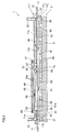
- FIG. 2 is a sectional view of the ink-jet head 1.
- FIG. 3 is a set of exploded plan views of a reservoir unit 3.
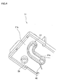
- FIG. 4 is a perspective view of a part of a passage component 11 that is included in the reservoir unit 3, as seen at an angle from below.
- FIG. 5 is a perspective view of a part of the passage component 11, as seen at an angle from above.
- FIG. 6 is a sectional view as taken along a line VI-VI of FIG. 3.
- the ink-jet head 1 is scaled up in its thickness direction.
- an ink passage formed in the reservoir unit 3 is illustrated, although it actually does not appear on a section that is taken along an identical line.
- FIG. 3 is a set of exploded plan views of a reservoir unit 3.
- FIG. 4 is a perspective view of a part of a passage component 11 that is included in the reservoir unit 3, as seen at an angle from below.
- FIG. 5 is a perspective view of a part of the passage component 11, as seen at an
- the uppermost one is the passage component 11 as seen from above, and the second uppermost one is the passage component 11 as seen from below.
- films 41, 42, 49, and a filter plate 54 which are shown in FIG. 2 are omitted for the purpose of easy understanding of a structure of the passage component 11.
- the reservoir unit 3 temporarily stores ink therein, and supplies ink to a passage unit 9 which is included in the head main body 2.
- the reservoir unit 3 has a layered structure in which the passage component 11 and three plates 12 to 14 are layered.
- the passage component 11 is elongated in the main scanning direction.
- Each of the three plates 12 to 14 has a rectangular plane elongated in the main scanning direction.
- the passage component 11 is made of a synthetic resin such as a polyethylene terephthalate resin, a polypropylene resin and the like.
- the plates 12 to 14 are metal plates made of, e.g., SUS430.
- cylindrical joints 31 and 32 protrude from a surface 11a of the uppermost passage component 11.
- the joint 31 is fitted into and thus connected to an ink supply tube (not shown).
- the joint 32 is fitted into and thus connected to an ink discharge tube (not shown).
- annular walls 37 and 38 protrude from a back face 11b of the passage component 11.
- the annular walls 37 and 38 enclose regions that correspond to the joints 31 and 32, respectively. Both of the annular walls 37 and 38 are opened toward the plate 12.
- the annular wall 37 curves into an L-shape, from a point corresponding to the joint 31.
- the annular wall 38 curves into an L-shape, from a point corresponding to the joint 32.
- a space in the annular wall 38 with respect to a sub scanning direction is increased from the point corresponding to the joint 32, and reduced in the vicinity of a center of the passage component 11. As shown in FIG.
- a protruding end 37a of the annular wall 37 has a tapered shape.
- the end 37a of the annular wall 37 is heated and melted through a film 41, so that the annular wall 37 is adhered to the film 41 (see FIG. 2).
- a left-side hatched region is a region adhered to the film 41.
- An opening of the annular wall 37 is thereby sealed, thus forming a space enclosed with the back face 11b, the annular wall 37, and the film 41. That is, a flow-in passage 45 communicating with the joint 31 and a later-described hole 46 is formed.
- the end 37a of the annular wall 37 has a tapered shape, and therefore is easily melted when heated. Accordingly, by heating the end 37a of the annular wall 37 through the film 41, the film 41 can easily be adhered to the annular wall 37 while preventing a portion of the annular wall 37 except the end 37a from being melted. Even if the end 37a has an inaccurate flatness, inaccuracy can be compensated because the end 37a is melted down.
- a protruding end of the annular wall 38 has a tapered shape.
- the protruding end is melted so that the annular wall 38 is adhered to the film 42 (see FIG. 2).
- a right-side hatched region is a region adhered to the film 42.
- An opening of the annular wall 38 is thereby sealed.
- circular holes 46 and 47 are formed on the surface 11a of the passage component 11 and penetrate to the back face 11b.
- the hole 46 is positioned so as to communicate with a downstream end of the flow-in passage 45.
- the hole 47 is formed at a position that is a little closer to the joint 32 than the center of the passage component 11 is.
- the hole 47 is positioned so as to communicate with an upstream end of the discharge passage 44.
- annular wall 48 that encloses the hole 46 and the hole 47 protrudes from the surface 11a.
- a space in the annular wall 48 with respect to the sub scanning direction is increased along a longitudinal direction of the passage component 11 from a vicinity of the hole 46 to a vicinity of both sides of the passage component 11, and then the annular wall 48 extends along the both sides to a vicinity of the center, and then the space is reduced toward the hole 47.
- a protruding end 48a of the annular wall 48 has a tapered shape.
- FIG. 3 shows two annular hatched regions, the external one of which is a region that is adhered to the film 49.
- the film 49 has flexibility, and its upper face is touched by the atmosphere.
- the film 49 also works as a damper for damping vibration of ink.
- An opening of the annular wall 48 is thereby sealed, thus forming a space enclosed with the surface 11a, the annular wall 48, and the film 49. That is, a filter chamber 55 provided therein with a later-described filter plate 54 is formed.
- the end 48a of the annular wall 48 has a tapered shape, and therefore is easily melted when heated. Accordingly, by heating the end 48a of the annular wall 48 through the film 49, the film 49 can easily be adhered to the annular wall 48 while preventing a portion of the annular wall 48 except the end 48a from being melted. Even if the end 48a has an inaccurate flatness, inaccuracy can be compensated because the end 48a is melted down.
- the films 41, 42, and 49 are made of a material having excellent gas barrier properties such as a PET (polyethylene terephthalate) film on which a silica film (SiOx film), an aluminum film, or the like is vapor-deposited.
- a PET polyethylene terephthalate
- SiOx film silica film
- aluminum film aluminum film, or the like is vapor-deposited.
- a concavity 51 is formed inside the annular wall 48. As shown in the uppermost view of FIG. 3, the concavity 51 extends from a vicinity of the hole 46 to a vicinity of the center of the passage component 11. In a plan view, a shape of the concavity 51 is similar to but slightly smaller than that of the annular wall 48. A circular hole 52 is formed on a bottom face of the concavity 51 and in the vicinity of the center of the passage component 11.
- a filter plate 54 (see FIG. 2) is supported on an annular face 53 that encloses the concavity 51.
- the annular face functions as a filter support face.
- the uppermost view of FIG. 3 shows two annular hatched regions, the internal one of which is the annular face 53.
- An outer edge of the annular face 53 is defined by an annular wall 58 that is protrudingly formed along an outer edge of the filter plate 54.
- a height of the annular wall 58 is lower than a height of the annular wall 48 that defines the filter chamber 55.
- the filter plate 54 will be described with reference to FIGS. 7A and 7B.
- a shape of the filter plate 54 is similar to but slightly larger than that of the concavity 51.
- the filter plate 54 is made of nickel manufactured through an electroforming process for example, and has a melting point higher than a melting point of the passage component 11.
- the filter plate 54 has an inner region 61 that is opposed to the concavity 51, and an annular region 62 that is opposed to the annular face 53 and surrounds the inner region 61. Many fine holes 54a through which ink is filtered are formed in the inner region 61.
- the annular region 62 includes a first non-pieced area 63, a second non-pierced area 64, and an intermediate area 65.
- the first non-pierced area 63 is adjacent to an outer edge of the inner region 61, and has no through hole formed therein.
- the second non-pierced area 64 is continuous with the outer edge of the filter plate 54, and has no through hole formed therein.
- the intermediate area 65 is formed between the non-pierced areas 63 and 64. Many holes 54b are formed in the intermediate area 65. That is, the holes 54a and 54b are formed in hatched regions in FIG. 7A.
- the non-pierced areas 63 and 64 have the same width S.
- the width S is larger than a pitch P between the holes 54a that are formed in the inner region 61.
- a diameter of the hole 54a formed in the inner region 61 is larger than a diameter of the hole 54b formed in the intermediate area 65.
- a diameter of the hole 54a may not be larger than a diameter of the hole 54b.
- the filter plate 54 is disposed on the annular face 53 in such a manner that the non-pierced area 63 locates in a plane-direction extension of an inner surface 51a of a side wall of the concavity 51.
- the inner surface 51a is continuous with an inner circumferential border of the annular face 53, and extends in a direction perpendicular to the annular face 53. Therefore, the inner region 61 of the filter plate 54 is entirely opposed to the concavity 51, and the non-pierced region 64 and the intermediate region 65 of the annular region 62 are entirely opposed to the annular face 53, and the non-pierced region 63 is partially opposed to the annular face 53.
- the annular face 53 is in contact with the annular region 62 of the filter plate 54, but out of contact with the inner region 61.
- radially-expanding protrusions 56 are formed on the annular face 53.
- the radially-expanding protrusions 56 are embedded in the respective holes 54b of the intermediate area 65. Beyond the hole 54b and on an upper face of the filter plate 54, the protrusion 54 radially expands so that its diameter is larger than a diameter of the hole 54. Portions of the radially-expending protrusions 56 beyond the holes 54b are connected and integrated with each other, thus forming a resin layer 57.
- the resin layer 57 is formed throughout, among an upper face of the annular region 62, an area corresponding to the annular face 53. Thus, in a plan view, the resin layer 57 has an annular shape.
- the width of the non-pierced area 63 is set such that the resin layer 57 does not spread to the inner region 61. Thus, filtration properties of the filter plate 54 are not spoiled.
- a shape of the annular wall 58 is similar to and a slightly larger than the shape of the filter plate 54.
- the annular wall 58 encloses the filter plate 54 at a distance from the filter plate 54.
- a level of the annular wall 58 is higher than a level of the upper face of the filter plate 54.
- the annular wall 58 functions as a guide when the filter plate 54 is disposed, to allow the filter plate 54 to be easily disposed on the annular face 53. In this way, the filter plate 54 is fixed within the filter chamber 55 of the passage component 11.
- the diameter of the hole 54b formed in the intermediate area 65 is smaller than the diameter of the hole 54a formed in the inner region 61. Consequently, even when the hole 54b is not closed with the radially-expanding protrusion 56 but is connected to the hole 54a in parallel through a bypass passage, the hole 54b does not permit any foreign matter having a size equal to or larger than a size permitted through the hole 54a because of a size relationship. That is, in the present invention, it is not necessary that all the holes 54b are closed with the radially-expanding protrusions 56.
- a curved passage 60 is formed in the passage component 11.
- the curved passage 60 extends from the hole 46 to the hole 52 through the filter chamber 55 and a space formed within the concavity 51.
- the curved passage 60 is connected also to the discharge passage 44 via the hole 47.
- an annular groove 67 that opens downward is formed around the hole 52.
- An O-ring 68 is fitted in the annular groove 67.
- the passage component 11 has four circular holes 59 passing therethrough from the surface 11a to the back face 11b. Two of the holes 59 locate in a middle portion of the passage component 11 and two of them locate at both end portions of the passage component 11, with respect to the longitudinal direction of the passage component 11. The holes 59 are arranged point-symmetrically with respect to the center of the passage component 11.
- circular holes 71 and 72 are formed at both longitudinal end portions of the plate 12 which is disposed just under the passage component 11.
- the holes 71 and 72 are used for fixing the ink-jet head 1 to a printer main body by use of screws or the like.
- the plate 12 has a circular hole 73 at its center, and positioning holes 75a and 75b at its portion that is a little closer to the center than the holes 71 and 72 are.
- the plate 12 further has four screw holes 76. Two of the screw holes 76 locate in a middle portion of the plate 12 and two of them locate at both end portions of the plate 12, with respect to the longitudinal direction of the plate 12.
- the screw holes 76 are arranged point-symmetrically with respect to the center of the plate 12.
- the screw holes 76 correspond to the above-described holes 59, respectively.
- the passage component 11 and the plate 12 are fixed to each other.
- the hole 52 of the passage component 11 and the hole 73 of the plate 12 are opposed to each other so that the curved passage 60 of the passage component 11 communicates with the hole 73. Since the O-ring 68 is fitted in the annular groove 67, ink does not leak out at an outlet of the curved passage 60 into between the passage component 11 and the plate 12.
- a plate 13 which is disposed immediately under the plate 12, has a through hole 81.
- the through hole 81 forms a reservoir passage 85 that includes a main passage 82 and ten branch passages 83 communicating with the main passage 82.
- the reservoir passage 85 is point-symmetrical with respect to a center of the plate 13.
- the main passage 82 extends along a longitudinal direction of the plate 13. Substantially a center of the main passage 82 corresponds to the hole 73 of the plate 12.
- a passage width of the branch passage 83 is smaller than a passage width of the main passage 82. All of the branch passages 83 have the same passage width, the same passage length, and substantially the same passage resistance.
- the plate 13 further has positioning holes 86a and 86b that correspond to the positioning holes 75a and 75b of the plate 12, respectively, and positioning holes 87a and 87b that are for positioning the plate 13 with a plate 14.
- the lowermost plate 14 of the reservoir unit 3 has ink discharge holes 88 each having an elliptical shape.
- the ink discharge holes 88 are formed at positions corresponding to ends of the respective branch passages 83.
- the plate 14 further has four positioning holes 91a, 91b, 92a, and 92b corresponding to the positioning holes 86a, 86b, 87a, and 87b of the plate 13, respectively.
- protrusions 89a, 89b, 89c, and 89d On a lower face of the plate 14, portions hatched in FIG. 3 protrude downward, to form protrusions 89a, 89b, 89c, and 89d.
- Each of the protrusions 89a, 89b, 89c, and 89d covers two or three ink discharge holes 88, and is fixed to an upper face of the passage unit 9 via a filter plate 95a or 95b (see FIG. 8).
- a portion of the plate 14 other than the protrusions 89a to 89d is spaced apart from the passage unit 9, so that a space is formed.
- the FPCs 6 (see FIG. 1) extend through the space.
- the three plates 12 to 14 are positioned with one another, and fixed by an adhesive.
- the reservoir unit 3 having the passage component 11 and the three plates 12 to 14 layered on one another is formed.
- ink that has flown through the joint 31 into the passage component 11 flows horizontally through the flow-in passage 45, and then flows upward through the hole 46, and then flows into the curved passage 60.
- some of the ink that has flown into the curved passage 60 flows through the hole 47 into the discharge passage 44 and then into the joint 32.
- air existing on an upper face of the filter plate 54 is also discharged together with the ink, so that fresh ink is charged on an upstream side of the filter plate 54.
- the ink that has flown into the filter chamber 55 passes through the holes 54a of the filter plate 54, and falls into the concavity 51.
- the ink that has fallen into the concavity 51 passes through the holes 52 and 73, and falls into the reservoir passage 85.
- the ink flows from the center of the main passage 82 toward both longitudinal ends of the main passage 82, as indicated by arrows in the fourth view from the top of FIG. 3.
- the ink reaches the both longitudinal ends of the main passage 82, and flows into the respective branch passages 83.
- the ink that has flown into the respective branch passages 83 passes through the ink discharge holes 88 and holes (not shown) formed in the filter plates 95a and 95b, and then flows through ink supply ports 101 into the passage unit 9.
- the ink that has flown into the passage unit 9 is, as will be described later, distributed to many individual ink passages 132 (see FIG. 10) that communicate with manifold channels 105.
- the ink then reaches nozzles 108 which are terminals of the respective individual ink passages 132, and then ejected to outside.
- FIG. 8 is a plan view of the head main body 2.
- FIG. 9 is an enlarged view of a region that is, in FIG. 8, enclosed with an alternate long and short dash line.
- pressure chambers 110, apertures 112, and nozzles 108 are illustrated with solid lines although they locate below the actuator units 21 and therefore should actually be illustrated with broken lines.
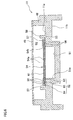
- FIG. 10 is a local sectional view as taken along a line X-X of FIG. 9.
- FIG. 11A is an enlarged sectional view of the actuator unit 21, and
- FIG. 11B is a plan view of an individual electrode 135 that is disposed on a surface of the actuator unit 21.
- the head main body 2 includes the passage unit 9 and four actuator units 21 that are fixed on the upper face of the passage unit 9.
- the actuator unit 21 includes actuators each corresponding to each pressure chamber 110, and has a function of selectively applying ejection energy to ink contained within the pressure chambers 110 that are formed on the passage unit 9.
- An outer shape of the passage unit 9 is a substantially rectangular parallelepiped shape having substantially the same width as that of the reservoir unit 3.
- a length of the passage unit 9 with respect to the main scanning direction is slightly smaller than that of the reservoir unit 3.
- a lower face of the passage unit 9 is an ink ejection face in which many nozzles 108 are arranged in a matrix. Portions of the ink ejection face which correspond to portions where the actuator units 21 are bonded are ink ejection regions.
- On the upper face of the passage unit 9 many pressure chambers 110 are formed in a matrix like the nozzles 108. Formed within the passage unit 9 are many individual ink passages 132 each corresponding to each pressure chamber 110 and each nozzle 108.
- Positioning holes 102a and 102b corresponding to the positioning holes 87a, 87b, 92a, and 92b of the plates 13 and 14 are formed at both longitudinal ends of the passage unit 9. By putting positioning pins through the positioning holes 87a, 87b, 92a, 92b, 102a and 102b, the passage unit 9 and the reservoir unit 3 are positioned with each other.
- the passage unit 9 has nine plates of, from the top, a cavity plate 122, a base plate 123, an aperture plate 124, a supply plate 125, manifold plates 126, 127, 128, a cover plate 129, and a nozzle plate 130.
- Each of the plates 122 to 130 is, like the plates 12 to 14 of the reservoir unit 3, made of SUS430 for example and, in a plan view, has a rectangular shape elongated in the main scanning direction (see FIG. 1).
- Formed in the cavity plate 122 are through holes serving as the ink supply ports 101 (see FIG. 8) and many substantially rhombic through holes serving as the pressure chambers 110.
- Formed in the base plate 123 are communication holes each provided for each pressure chamber 110 so as to connect a pressure chamber 110 to an aperture 112, and communication holes each provided for each pressure chamber 110 so as to connect a pressure chamber 110 to a nozzle 108.
- Also formed in the base plate 123 are communication holes each connecting an ink supply port 101 to a manifold channel 105.
- Formed in the aperture plate 124 are through holes each provided for each pressure chamber 110 and serving as an aperture 112, and communication holes each provided for each pressure chamber 110 so as to connect a pressure chamber 110 to a nozzle 108.
- Formed in the supply plate 125 are communication holes each provided for each pressure chamber 110 so as to connect an aperture 112 to a sub manifold channel 105a, and communication holes each provided for each pressure chamber 110 so as to connect each pressure chamber 110 to a nozzle 108.
- Also formed in the supply plate 125 are communication holes each connecting an ink supply port 101 to a manifold channel 105.
- manifold plates 126, 127, and 128 are through holes that cooperate with each other to constitute manifold channels 105 or sub manifold channels 105a when the plates are put in layers.
- Formed in the cover plate 129 are communication holes each provided for each pressure chamber 110 so as to connect a pressure chamber 110 to a nozzle 108.
- Formed in the nozzle plate 130 are through holes each provided for each pressure chamber 110 and serving as each nozzle 108.
- the nine plates 122 to 130 are positioned, put in layers, and fixed to one another so that an individual ink passage 132 as shown in FIG. 10 is formed inside the passage unit 9.
- a total of ten ink supply ports 101 are opened on the upper face of the passage unit 9.
- the ten ink supply ports 101 correspond to the ink discharge holes 88 of the reservoir unit 3 (see the lowermost view of FIG. 3).
- Manifold channels 105 that communicate with the ink supply ports 101, and sub manifold channels 105a that branch from the manifold channels 105 are formed within the passage unit 9.
- Individual ink passages 132 are provided for the respective nozzles 108. As shown in FIG. 8, each of the individual ink passages 132 extends from a manifold channel 105 to a nozzle 108 through a sub manifold channel 105a, an outlet of the sub manifold channel 105a, an aperture 112, and a pressure chamber 110.
- Ink is supplied from the reservoir unit 3 through the ink supply ports 101 into the passage unit 9, and then branches from the manifold channels 105 into the sub manifold channels 105a, and then goes through the apertures 112 which function as throttles and the pressure chambers 110 to the nozzles 108.
- the filter plates 95a and 95b that cover the ink supply ports 101 are disposed on the upper face of the passage unit 9.
- Each of the two filter plates 95a extends obliquely with respect to a widthwise direction of the passage unit 9, so as to cover the ink supply ports 101 that locate at each longitudinal end portion of the passage unit 9.
- Each of the four filter plates 95b has a shape elongated in a longitudinal direction of the passage unit 9.
- the ink supply ports 101 are paired and arranged in a zigzag pattern along the longitudinal direction of the passage unit 9.
- the four filter plates 95b are disposed so that each of them covers two of the ink supply ports 101.
- the filter plates 95a and 95b are disposed in regions to which the protrusions 89a to 89d (as illustrated with alternate long and two short dashes lines in FIG. 8) of the plate 14 of the reservoir unit 3 are fixed.
- the filter plates 95a and 95b are bonded to portions of lower faces of the protrusions 89a to 89d except the ink discharge holes 88.
- Portions of the lower faces of the protrusions 89a to 89d which are not opposed to the filter plates 95a and 95b are bonded to the upper face of the passage unit 9 by an adhesive.
- the four actuator units 21 each having a trapezoidal shape in a plan view are arranged in a zigzag pattern so as to keep out from the ink supply ports 101 and the filter plates 95a, 95b.
- Parallel opposed sides of each actuator unit 21 extend along the longitudinal direction of the passage unit 9. Oblique sides of every neighboring actuator units 21 overlap each other with respect to the widthwise direction of the passage unit 9. Neighboring actuator units 21 locate equidistantly on opposite sides of a widthwise center of the passage unit 9.
- the reservoir unit 3 is fixed to the passage unit 9 with the protrusions 89a to 89d therebetween.
- the portion of the lower face of the reservoir unit 3 other than the protrusions 89a to 89d (which is not hatched in the lowermost view of FIG. 3) is spaced apart from the passage unit 9 at an interval corresponding to a protruding height of the protrusions 89a to 89d.
- the actuator units 21 are fixed to portions of the upper face 9a of the passage unit 9 which are spaced apart from and opposed to the lower face of the reservoir unit 3.
- the FPCs 6 fixed on the actuator units 21 are not in contact with the lower face of the reservoir unit 3.
- the actuator unit 21 includes three piezoelectric sheets 141, 142, and 143 each having a thickness of approximately 15 ⁇ m and made of, for example, a lead zirconate titanate (PZT)-base ceramic material with ferroelectricity.
- the piezoelectric sheets 141 to 143 are disposed so as to extend over many pressure chambers 110 that correspond to one ink ejection face.
- individual electrodes 135 are formed at positions corresponding to the respective pressure chambers 110.
- a common electrode 134 having a thickness of approximately 2 ⁇ m is interposed between the uppermost piezoelectric sheet 141 and the piezoelectric sheet 142 disposed under the uppermost piezoelectric sheet 141.
- the common electrode 134 is formed over entire surfaces of the sheets.
- Both of the individual electrodes 135 and the common electrode 134 are made of an Ag-Pd-base metallic material for example. No electrode is disposed between the piezoelectric sheets 142 and 143.
- the individual electrode 135 has a thickness of approximately 1 ⁇ m. In a plan view, as shown in FIG. 11B, the individual electrode 135 has a substantially rhombic shape similar to that of the pressure chamber 110. One acute portion of the individual electrode 135 extends out. Formed at an end of the acute portion is a circular land 136 having a diameter of approximately 160 ⁇ m and electrically connected to the individual electrode 135.
- the land 136 is made of gold including glass frits, for example.
- the land 136 is, at a predetermined position on an extending-out portion of the individual electrode 135, electrically bonded to a contact that is provided on the FPC 6 (see FIG. 1).
- the position is, with respect to a thickness direction of the piezoelectric sheets 141 to 143, opposed to a wall of the cavity plate 122 defining the pressure chambers 110. That is, the position does not overlap the pressure chamber 110 with respect to the thickness direction of the piezoelectric sheets 141 to 143.
- the common electrode 134 is grounded.
- the common electrode 134 is, at its portions corresponding to all the pressure chambers 110, equally kept at the ground potential.
- the FPC 6 through which the individual electrodes 135 are connected to the driver IC 7 includes lead wires that are provided for the respective individual electrodes 135 independently of one another. That is, a portion of the actuator unit 21 sandwiched between each individual electrode 135 and the pressure chamber 110 works as an individual actuator. The number of actuators included in the actuator unit 21 equals the number of pressure chambers 110.
- the piezoelectric sheet 141 is polarized in its thickness direction.
- an electric field in a polarization direction is applied to the piezoelectric sheet 141.
- a portion of the piezoelectric sheet 141 to which the electric field is applied acts as an active portion which is distorted by a piezoelectric effect. That is, the piezoelectric sheet 141 extends or contracts in its thickness direction, and contracts or extends in a plane direction by a transversal piezoelectric effect.
- the other two piezoelectric sheets 142 and 143 form inactive layers not including a region sandwiched between the individual electrode 135 and the common electrode 134, and therefore cannot deform by themselves. That is, the actuator unit 21 is of so-called unimorph type, in which upper one piezoelectric sheet 141 distant from the pressure chambers 110 is a layer including active portions and the lower two piezoelectric sheet 142 and 143 closer to the pressure chambers 110 are layers including no active portions.
- the piezoelectric sheets 141 to 143 are fixed on an upper face of the cavity plate 122 that partitions the pressure chambers 110.
- the piezoelectric sheets 141 to 143 as a whole are deformed to protrude toward the pressure chamber 110 (unimorph deformation). This reduces the volume of the pressure chamber 110.
- Pressure inside the pressure chamber 110 rises accordingly, and ink is pushed out of the pressure chamber 110 to the nozzle 108 and then ejected from the nozzle 108.
- the piezoelectric sheets 141 to 143 restore the original flat shape, and the volume of the pressure chamber 110 is also returned to the original one. Ink is accordingly introduced from the manifold channel 105 into the pressure chamber 110, and thus the pressure chamber 110 is charged with ink again.
- FIG. 12 is a flow diagram showing a process of manufacturing the ink-jet head 1.
- a step is referred to as an abbreviated designation "S".
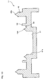
- FIG. 13 is a sectional view of the passage component 11 that is manufactured in S2 of FIG. 12.
- FIGS. 14A, 14B, and 14C are views explanatory of procedures for fixing the filter plate 54 to the passage component 11.
- respective parts such as the reservoir unit 3, the passage unit 9, and the actuator unit 21 are separately prepared, and then the parts are assembled to each other.
- the plates 12 to 14 are first prepared (S1). At this time, three plates intended to form a part of the reservoir unit 3 are subjected to an etching process using a patterned photoresist as a mask, so that holes shown in the third to fifth views from the top in FIG. 3 are formed in the respective plates. Then, the passage component 11 made of resin is prepared by a known molding method (S2: passage component preparation step). In the passage component 11, as shown in FIG. 13, a tapered protrusion 156 is formed on the annular face 53. The protrusion 156 is formed annularly over an entire circumference of the annular face 53.
- Parts of the passage component 11 except the filter plate 54 and the films 41, 42, and 49 are integrally formed. At this time, the protruding ends 37a, 38a, and 48a of the annular walls 37, 38, and 48 to which the films 41, 42, and 49 are welded are formed into tapered shapes.
- the holes and the like of the passage component 11 are formed at the time when the passage component 11 is formed, by a known molding method such as an injection molding.
- a filter plate 54 made of nickel is prepared by a known electroforming process by use of a mask having an inverse pattern of a pattern of the filter plate 54, that is, by use of a resist layer (S3: filter plate preparation step).
- the intermediate area 65 of a lower face of the filter plate 54 is brought into contact with an end of the protrusion 156 (S4: contact step).
- the inner region 61 of the filter plate 54 is opposed to the concavity 51 of the passage component 11, while the non-pierced area 63 of the filter plate 54 is opposed to the inner circumferential border of the annular face 53 which is defined by the inner surface 51a.
- the non-pierced area 63 and the inner circumferential border of the annular face 53 are in contact with each other. This can prevent stress concentration, which occurs on the filter plate 54 when ink passes through the filter plate 54, from occurring in the inner region 61.
- a life of the filter plate 54 is elongated accordingly.
- the level of the annular wall 58 is slightly higher than the level of the upper face of the filter plate 54 put on the protrusion 156.
- the annular wall 58 functions as a guide when the filter plate 54 is disposed, to allow the filter plate 54 to be easily disposed on the annular face 53.
- an upper face of the filter plate 54 is heated and pressed by a flat lower face of a jig 160 having a heater provided therein (S5: heating and pressing step).
- the jig 160 is set at a temperature that allows the protrusion 156 to be melted but the filter plate 54 not to be melted.
- the protrusion 156 is also heated.
- the protrusion 156 is melted upon reaching its melting temperature.
- FIG. 14C the melted protrusion 156 enters and goes through the holes 54b.
- the melted protrusion 156 radially expands on the upper face of the filter plate 54 so that its diameter is larger than a diameter of each hole 54.
- Portions of the protrusion 156 beyond the holes 54b spread substantially throughout an area on the upper side of the annular region 62 corresponding to the annular face 53. The portions are connected to each other.
- the jig 160 is withdrawn to cool the melted protrusion 156.
- the above-described radially-expanding protrusions 56 and resin layer 57 are formed, thereby fixing the filter plate 54 to the passage component 11.
- the passage component 11 and the three plates 12 to 14 are positioned in layers.
- the passage component 11 and the plate 12 are fixed with screws, and the three plates 12 to 14 are fixed with an adhesive, to thereby manufacture the reservoir unit 3 (S7).
- each of the nine plates 122 to 130 included in the passage unit 9 is subjected to an etching process using a patterned photoresist as a mask, so that holes shown in FIG. 10 are formed in the plates. Then, the plates 122 to 130 are positioned to each other so as to form the individual ink passage 132 therein, and put on one another with an epoxy-base thermosetting adhesive being therebetween. Then, the plates 122 to 130 are pressurized and heated up to a curing temperature of the thermosetting adhesive or higher. As a result, the thermosetting adhesive is cured, to secure the plates 122 to 130 to each other. Thus, the passage unit 9 as shown in FIG. 10 is obtained (S8).
- the piezoelectric actuator 21 To prepare the piezoelectric actuator 21, first, three green sheets made of piezoelectric ceramics are prepared. The green sheets are in advance formed so as to allow for contraction which will be caused during a baking procedure. On one of the green sheets, a conductive paste is screen printed in a pattern of the common electrode 134. Then, the green sheets are positioned to each other using a jig. The green sheet on which the conductive paste is printed in the pattern of the common electrode 134 is put under a green sheet on which no conductive paste is printed. Further, the other green sheet on which no conductive paste is printed is put under the aforesaid green sheet on which the conductive paste is printed in the pattern of the common electrode 134 (S9).
- a layered structure thus obtained in S9 is degreased in the same manner as for a known ceramics, and further baked at a predetermined temperature (S10). Consequently, the three green sheets become the piezoelectric sheets 141 to 143, and the conductive paste becomes the common electrode 134. Then, on the uppermost piezoelectric sheet 141, a conductive paste is screen-printed in a pattern of the individual electrodes 135. The layered structure is heat-treated to bake the conductive paste, so that the individual electrodes 135 are formed on the piezoelectric sheet 141. Thereafter, gold including glass frits is printed on the individual electrodes 135, to form the lands 136. In this way, the actuator unit 21 as shown in FIG. 11A is prepared.
- the reservoir unit preparation steps S1 to S7, the passage unit preparation step S8, and the actuator unit preparation step S9 to S10 are performed independently of one another, and therefore they may be performed either concurrently or in a random order.
- thermosetting adhesive is applied to an upper face of the passage unit 9 obtained in S8 on which many openings for the pressure chambers 110 are formed (S11).
- thermosetting adhesive include two-liquid mixed type one.
- the actuator unit 21 is disposed on the thermosetting adhesive layer that is applied to the passage unit 9 (S12). At this time, the actuator unit 21 is supported on walls of the cavity plate 122 defining the pressure chambers 110. In addition, the actuator unit 21 is positioned relative to the passage unit 9 in such a manner that the individual electrodes are opposed to the respective pressure chambers 110. The positioning is based on positioning marks (not shown) that have been provided on the passage unit 9 and the actuator unit 21 previously in S8 to S10. At this time, moreover, six filter plates 95a and 95b are disposed so as to cover the respective ink supply ports 101.
- thermosetting adhesive existing between the passage unit 9 and the actuator unit 21, and the actuator unit 21 is pressurized while heated up to a curing temperature of the thermosetting adhesive or higher (S13).
- the openings for the pressure chambers 110 are closed with the actuator unit 21, and the filter plates 95a and 95b are fixed on the passage unit 9.
- the layered structure is taken out of the heat/pressure device, and cooled (S14). In this way, the head main body 2 made up of the passage unit 9 and the actuator unit 21 is manufactured.
- the FPC 6 is electrically connected to the actuator unit 21 (S15) .
- an epoxy-base thermosetting adhesive is applied to lower faces of the protrusions 89a to 89d of the reservoir unit 3 (S16).
- Positioning pins are put through the positioning holes 87a, 87b, 92a, and 92b which are formed in the reservoir unit 3 and through the positioning holes 102a and 102b which are formed in the passage unit 9, thereby positioning the reservoir unit 3 and the head main body 2 to each other.
- a heat/pressure device not shown
- a layered structure of the reservoir unit 3 and the head main body 2 is pressurized while heated up to a curing temperature of the thermosetting adhesive or higher (S17).
- the lower faces of the protrusions 89a to 89d are fixed to the upper face of the passage unit 9 with the filter plates 95a and 95b therebetween. Then, the layered structure is taken out of the heat/pressure device, and cooled (S18). In this way, the ink-jet head 1 is manufactured.
- the filter plate 54 and the passage component 11 are fixed to each other by an adhesive only, the adhesive sometimes cannot provide sufficient adhesion depending on materials of the filter plate 54 and the passage component 11.
- the filter plate 54 is fixed to the passage component 11 by means of the radially-expanding protrusions 56. This can reduce the problem of separation of the filter plate 54.
- Portions of the radially-expanding protrusions 56 beyond the holes 54 are connected to each other, thus forming the resin layer. This makes it more difficult for the filter plate 54 to be separated from the passage component 11.
- the portions of the radially-expanding protrusions 56 beyond the holes 54b hardly reaches the inner region 61. That is, since the holes 54b and the holes 54a are separated by the first non-pierced area 63, the holes 54a can be prevented from being closed with the portions of the radially-expanding protrusions 56 beyond the holes 54b, that is, the resin layer 57. This can prevent reduction of an effective filtration area of the filter plate 54 which may be caused if the holes 54a of the inner region 61 are closed. That is, in this embodiment, an effective filtration area of the filter plate 54 is constant, and does not vary among heads 1.
- the non-pieced area 63 in which no hole is formed, is stronger than either of the inner region 61 in which the holes 54a are formed and the intermediate area 65 in which the holes 54b are formed. Therefore, even though the filter plate 54 vibrates when ink passes therethrough, the filter plate 54 is not easily damaged.
- the non-pierced area 64 improves rigidity of the filter plate 54, and functions as a reinforcement of the filter plate 54. Due to presence of the non-pierced area 64, vibration of the filter plate 54 in its outer periphery, which occurs when ink passes through the filter plate 54, can be suppressed as compared with the filter plate having holes in its outer periphery. This can prevent a part of the outer periphery of the filter plate 54 from falling out to cause a foreign matter. In addition, since no hole is formed in the non-pieced area 64, strength of the filter plate 54 is improved even more. Therefore, the filter plate 54 can handle easily.
- a diameter of the hole 54b which is formed in the intermediate area 65 is smaller than a diameter of the hole 54a which is formed in the inner region 61. Therefore, even though the radially-expanding protrusions 56 are not embedded in some holes 54b, the holes 54b do not permit a foreign matter to pass therethrough and only ink is permitted to pass through the holes 54b. That is, the intermediate area 65, in which a hole 54b having no radially-expanding protrusions 56 embedded therein exists, can catch a smaller foreign matter than the inner region 61 can. Therefore, initial performance of the filter plate 54 is not spoiled.
- the protrusion 156 that is formed on the annular face 53 of the passage component 11 is melted in the heating and pressing step S5, and the melted protrusion 156 is embedded in the holes 54b that are formed in the filter plate 54. Further, portions of the melted protrusion 156 beyond the holes 54b radially expand, and a diameter of each of the portions becomes larger than a diameter of each hole 54b. Therefore, the filter plate 54 is fixed to the passage component 11 with a problem of separation of the filter plate 54 reduced.
- the protrusion 156 is formed in a tapered shape. Therefore, an end of the protrusion 156 can easily be melted in S5. This can ensure that the filter plate 54 is fixed. In addition, even if the end of the protrusion 156 has an inaccurate flatness before being melted, the inaccuracy can be compensated at the time when the end of the protrusion 156 is melted down.
- radially-expanding protrusions 56 are provided. However, it suffices that at least one radially-expanding protrusion 56 is embedded in any of the holes 54b and a portion of the protrusion 56 beyond the hole 54b radially expands to have a diameter larger than a diameter of the hole 54b.
- the protrusion 156 may not be embedded in all the holes 54b, but may embedded in some of the holes 54b. It may also be possible that a part of the protrusion 156 radially expands.
- the radially-expanding protrusions 56 may not necessarily form the resin layer 57.
- the portions of the radially-expanding protrusions 56 beyond the holes 54b may not be connected to each other but may increase their own diameters independently of one another.
- the resin layer 57 may not be formed over an entire circumference of the annular region 62. In such a case as well, the filter plate 54 is well fixed to the annular face 53.
- the filter plate 54 has either one of the non-pierced areas 63 or 64. Alternatively, it may also be possible that the filter plate 54 has neither of the non-pierced areas 63 nor 64.
- a diameter of the hole 54b that is formed in the annular region 62 may be larger than a diameter of the hole 54a that is formed in the inner region 61, as long as an upper face of the intermediate region 65 is fully covered with the resin layer 57.
- the end of the protrusion 156 may not have a tapered shape.
- the ink-jet head according to the present invention may be manufactured by a method other than that described in the above embodiment.
- the filter plate 54 may be placed on the annular face 53 on which no protrusion 156 is formed. Then, resin is filled in the holes 54b formed in the filter plate 54, and a resin plate functioning as the resin layer 57 is placed on the upper face of the filter plate 54. In this condition, the resin plate is heated and pressed to thereby form the radially-expanding protrusions 56 and the resin layer 57 as shown in FIG. 14C.
- the ink-jet head according to the present invention is not limited to piezo-type ink-jet heads, and may be thermal-type ink-jet heads, electrostatic-type ink-jet heads, and the like. Moreover, applications of the ink-jet head according to the present invention are not limited to printers. It is also applicable to ink-jet type facsimiles or copying machines.
Landscapes
- Engineering & Computer Science (AREA)
- Mechanical Engineering (AREA)
- Manufacturing & Machinery (AREA)
- Physics & Mathematics (AREA)
- Thermal Sciences (AREA)
- Particle Formation And Scattering Control In Inkjet Printers (AREA)
Abstract
Description
- The present invention relates to an ink-jet head that ejects ink from a nozzle, and also to a method of manufacturing the ink-jet head.
-
Japanese Patent Unexamined Publication No. 2004-268454 - In the ink-jet head disclosed in the above-mentioned document, however, if either one of the flange and the filter plate is made of a resin, the adhesive cannot exhibit sufficient adhesion and the filter plate may be separated.
- An object of the present invention is to provide an ink-jet head that suppress separation of a filter plate, and also to provide a method of manufacturing the ink-jet head.
- According to a first aspect of the present invention, there is provided an ink-jet head comprising a passage component made of resin and a filter plate through which ink is filtered. The filter plate is fixed to the passage component and has a melting point higher than that of the passage component. The filter plate has an annular region and an inner region surrounded by the annular region, and a plurality of holes are formed through the filter plate in a thickness direction of the filter plate, in the annular region and the inner region, respectively. The passage component has a filter support face that supports one face of the filter plate extending in a direction perpendicular to the thickness direction. The filter support face is in contact with the annular region but out of contact with the inner region. A holder is formed on the filter support face. The holder penetrates through at least one of the holes formed in the annular region and covers the other face of the filter plate.
- According to a second aspect of the present invention, there is provided a method of manufacturing an ink-jet head that includes a passage component made of resin and a filter plate through which ink is filtered. The filter plate is fixed to the passage component and has a melting point higher than that of the passage component. The method comprises the steps of: preparing the passage component having an annular face that annularly extends in a plane, a step face that is continuous with an inner circumferential border of the annular face and extends in a direction crossing the plane, and a protrusion that is formed on the annular face; preparing the filter plate through which a plurality of holes are formed in a thickness direction of the filter plate; bringing one face of the filter plate into contact with the protrusion while opposing one of the holes to the protrusion; and heating the protrusion and pressing the filter plate to the annular face, in such a manner that the melted protrusion is embedded in at least one of the holes and, in its portion beyond the holes, radially expands thus having a diameter larger than a diameter of the holes, to thereby fix the filter plate to the passage component.
- In the first and second aspects described above, the filter plate is fixed to the passage component by means of the holder or the protrusion. This can reduce a problem of separation of the filter plate.
- Other and further objects, features and advantages of the invention will appear more fully from the following description taken in connection with the accompanying drawings in which:
- FIG. 1 is a perspective view of an external appearance of an ink-jet head according to an embodiment of the present invention;
- FIG. 2 is a sectional view as taken along a line II-II of FIG. 1;
- FIG. 3 is a set of exploded plan views of a reservoir unit that is included in the ink-jet head;
- FIG. 4 is a perspective view of a part of a passage component that is included in the reservoir unit, as seen at an angle from below;
- FIG. 5 is a perspective view of a part of the passage component, as seen at an angle from above;
- FIG. 6 is a sectional view as taken along a line VI-VI of FIG. 3;
- FIG. 7A is a plan view of a filter plate;
- FIG. 7B is an enlarged plan view of a region that is, in FIG. 7A, enclosed with an alternate long and short dash line;
- FIG. 8 is a plan view of a head main body that is included in the ink-jet head;
- FIG. 9 is an enlarged view of a region that is, in FIG. 8, enclosed with an alternate long and short dash line;
- FIG. 10 is a local sectional view as taken along a line X-X of FIG. 9;
- FIG. 11A is an enlarged sectional view of an actuator unit;
- FIG. 11B is a plan view of an individual electrode that is disposed on a surface of the actuator unit;
- FIG. 12 is a flow diagram showing a process of manufacturing the ink-jet head;
- FIG. 13 is a sectional view of a passage component that is manufactured in a step S2 of FIG. 12; and
- FIGS. 14A, 14B, and 14C are views explanatory of procedures for fixing the filter plate to the passage component.
- In the following, a certain preferred embodiment of the present invention will be described with reference to the accompanying drawings.
- FIG. 1 is a perspective view of an external appearance of an ink-jet head according to an embodiment of the present invention. As shown in FIG. 1, an ink-
jet head 1 is elongated in a main scanning direction and has, from down to top, a headmain body 2 and a reservoir unit 3. The headmain body 2 is opposed to a record medium. The reservoir unit 3 temporarily stores ink therein. Four FPCs (Flexible Printed Circuits) 6, which work as power supply members, are put on an upper face of the headmain body 2, and extend upward through a space between the headmain body 2 and the reservoir unit 3. One end of the FPC 6 is connected to anactuator unit 21 which will be described later, and the other end thereof is connected to a control board (not shown). A driver IC 7 is mounted on the FPC 6 at a point midway from theactuator unit 21 to the control board. That is, the FPC 6 is electrically connected to the control board and thedriver IC 7, so that it transmits an image signal outputted from the control board to thedriver IC 7 and supplies a drive signal outputted from thedriver IC 7 to theactuator unit 21. - FIG. 2 is a sectional view of the ink-
jet head 1. FIG. 3 is a set of exploded plan views of a reservoir unit 3. FIG. 4 is a perspective view of a part of apassage component 11 that is included in the reservoir unit 3, as seen at an angle from below. FIG. 5 is a perspective view of a part of thepassage component 11, as seen at an angle from above. FIG. 6 is a sectional view as taken along a line VI-VI of FIG. 3. In FIG. 2, for the purpose of explanatory convenience, the ink-jet head 1 is scaled up in its thickness direction. Besides, an ink passage formed in the reservoir unit 3 is illustrated, although it actually does not appear on a section that is taken along an identical line. Among the views of FIG. 3, the uppermost one is thepassage component 11 as seen from above, and the second uppermost one is thepassage component 11 as seen from below. In FIGS. 3 to 5,films filter plate 54 which are shown in FIG. 2 are omitted for the purpose of easy understanding of a structure of thepassage component 11. - The reservoir unit 3 temporarily stores ink therein, and supplies ink to a
passage unit 9 which is included in the headmain body 2. As shown in FIG. 3, the reservoir unit 3 has a layered structure in which thepassage component 11 and threeplates 12 to 14 are layered. Thepassage component 11 is elongated in the main scanning direction. Each of the threeplates 12 to 14 has a rectangular plane elongated in the main scanning direction. Thepassage component 11 is made of a synthetic resin such as a polyethylene terephthalate resin, a polypropylene resin and the like. Theplates 12 to 14 are metal plates made of, e.g., SUS430. - As shown in FIGS. 2 and 3, in the vicinity of one longitudinal end and the other longitudinal end of the
passage component 11,cylindrical joints surface 11a of theuppermost passage component 11. The joint 31 is fitted into and thus connected to an ink supply tube (not shown). The joint 32 is fitted into and thus connected to an ink discharge tube (not shown). - As shown in FIGS. 3 and 4,
annular walls back face 11b of thepassage component 11. Theannular walls joints annular walls plate 12. In a plan view, theannular wall 37 curves into an L-shape, from a point corresponding to the joint 31. In a plan view, theannular wall 38 curves into an L-shape, from a point corresponding to the joint 32. A space in theannular wall 38 with respect to a sub scanning direction is increased from the point corresponding to the joint 32, and reduced in the vicinity of a center of thepassage component 11. As shown in FIG. 4, aprotruding end 37a of theannular wall 37 has a tapered shape. Theend 37a of theannular wall 37 is heated and melted through afilm 41, so that theannular wall 37 is adhered to the film 41 (see FIG. 2). In the second uppermost view of FIG. 3, a left-side hatched region is a region adhered to thefilm 41. An opening of theannular wall 37 is thereby sealed, thus forming a space enclosed with theback face 11b, theannular wall 37, and thefilm 41. That is, a flow-inpassage 45 communicating with the joint 31 and a later-describedhole 46 is formed. - The
end 37a of theannular wall 37 has a tapered shape, and therefore is easily melted when heated. Accordingly, by heating theend 37a of theannular wall 37 through thefilm 41, thefilm 41 can easily be adhered to theannular wall 37 while preventing a portion of theannular wall 37 except theend 37a from being melted. Even if theend 37a has an inaccurate flatness, inaccuracy can be compensated because theend 37a is melted down. - Like the
end 37a of theannular wall 37, a protruding end of theannular wall 38 has a tapered shape. In the same manner as described above, the protruding end is melted so that theannular wall 38 is adhered to the film 42 (see FIG. 2). In the second uppermost view of FIG. 3, a right-side hatched region is a region adhered to thefilm 42. An opening of theannular wall 38 is thereby sealed. Thus, in a space enclosed with theback face 11b, theannular wall 38, and thefilm 42, adischarge passage 44 communicating with the joint 32 and a later-describedhole 47 is formed. - As shown in FIG. 2 and in the uppermost and the second uppermost views of FIG. 3,
circular holes surface 11a of thepassage component 11 and penetrate to theback face 11b. Thehole 46 is positioned so as to communicate with a downstream end of the flow-inpassage 45. Thehole 47 is formed at a position that is a little closer to the joint 32 than the center of thepassage component 11 is. Thehole 47 is positioned so as to communicate with an upstream end of thedischarge passage 44. - As shown in the uppermost view of FIG. 3 and FIG. 5, an
annular wall 48 that encloses thehole 46 and thehole 47 protrudes from thesurface 11a. In a plan view, a space in theannular wall 48 with respect to the sub scanning direction is increased along a longitudinal direction of thepassage component 11 from a vicinity of thehole 46 to a vicinity of both sides of thepassage component 11, and then theannular wall 48 extends along the both sides to a vicinity of the center, and then the space is reduced toward thehole 47. As shown in FIG. 5, aprotruding end 48a of theannular wall 48 has a tapered shape. Theend 48a of theannular wall 48 is heated and melted through afilm 49, so that theannular wall 48 is adhered to the film 49 (see FIG. 2). The uppermost view of FIG. 3 shows two annular hatched regions, the external one of which is a region that is adhered to thefilm 49. Thefilm 49 has flexibility, and its upper face is touched by the atmosphere. Thefilm 49 also works as a damper for damping vibration of ink. An opening of theannular wall 48 is thereby sealed, thus forming a space enclosed with thesurface 11a, theannular wall 48, and thefilm 49. That is, afilter chamber 55 provided therein with a later-describedfilter plate 54 is formed. - The
end 48a of theannular wall 48 has a tapered shape, and therefore is easily melted when heated. Accordingly, by heating theend 48a of theannular wall 48 through thefilm 49, thefilm 49 can easily be adhered to theannular wall 48 while preventing a portion of theannular wall 48 except theend 48a from being melted. Even if theend 48a has an inaccurate flatness, inaccuracy can be compensated because theend 48a is melted down. - The
films jet head 1 can hardly enter an ink passage of thepassage component 11 through thefilm - As shown in FIGS. 2, 5, and 6, a
concavity 51 is formed inside theannular wall 48. As shown in the uppermost view of FIG. 3, theconcavity 51 extends from a vicinity of thehole 46 to a vicinity of the center of thepassage component 11. In a plan view, a shape of theconcavity 51 is similar to but slightly smaller than that of theannular wall 48. Acircular hole 52 is formed on a bottom face of theconcavity 51 and in the vicinity of the center of thepassage component 11. - A filter plate 54 (see FIG. 2) is supported on an
annular face 53 that encloses theconcavity 51. Thus, the annular face functions as a filter support face. The uppermost view of FIG. 3 shows two annular hatched regions, the internal one of which is theannular face 53. An outer edge of theannular face 53 is defined by anannular wall 58 that is protrudingly formed along an outer edge of thefilter plate 54. A height of theannular wall 58 is lower than a height of theannular wall 48 that defines thefilter chamber 55. - Here, the
filter plate 54 will be described with reference to FIGS. 7A and 7B. - In a plan view, a shape of the
filter plate 54 is similar to but slightly larger than that of theconcavity 51. Thefilter plate 54 is made of nickel manufactured through an electroforming process for example, and has a melting point higher than a melting point of thepassage component 11. Thefilter plate 54 has aninner region 61 that is opposed to theconcavity 51, and anannular region 62 that is opposed to theannular face 53 and surrounds theinner region 61. Manyfine holes 54a through which ink is filtered are formed in theinner region 61. Theannular region 62 includes a firstnon-pieced area 63, a secondnon-pierced area 64, and anintermediate area 65. The firstnon-pierced area 63 is adjacent to an outer edge of theinner region 61, and has no through hole formed therein. The secondnon-pierced area 64 is continuous with the outer edge of thefilter plate 54, and has no through hole formed therein. Theintermediate area 65 is formed between thenon-pierced areas Many holes 54b are formed in theintermediate area 65. That is, theholes - As shown in FIG. 7B, the
non-pierced areas holes 54a that are formed in theinner region 61. In this embodiment, a diameter of thehole 54a formed in theinner region 61 is larger than a diameter of thehole 54b formed in theintermediate area 65. However, a diameter of thehole 54a may not be larger than a diameter of thehole 54b. - Referring to FIG. 6 again, the
filter plate 54 is disposed on theannular face 53 in such a manner that thenon-pierced area 63 locates in a plane-direction extension of aninner surface 51a of a side wall of theconcavity 51. Theinner surface 51a is continuous with an inner circumferential border of theannular face 53, and extends in a direction perpendicular to theannular face 53. Therefore, theinner region 61 of thefilter plate 54 is entirely opposed to theconcavity 51, and thenon-pierced region 64 and theintermediate region 65 of theannular region 62 are entirely opposed to theannular face 53, and thenon-pierced region 63 is partially opposed to theannular face 53. In other words, theannular face 53 is in contact with theannular region 62 of thefilter plate 54, but out of contact with theinner region 61. - Many radially-expanding
protrusions 56 are formed on theannular face 53. The radially-expandingprotrusions 56 are embedded in therespective holes 54b of theintermediate area 65. Beyond thehole 54b and on an upper face of thefilter plate 54, theprotrusion 54 radially expands so that its diameter is larger than a diameter of thehole 54. Portions of the radially-expendingprotrusions 56 beyond theholes 54b are connected and integrated with each other, thus forming aresin layer 57. Theresin layer 57 is formed throughout, among an upper face of theannular region 62, an area corresponding to theannular face 53. Thus, in a plan view, theresin layer 57 has an annular shape. The width of thenon-pierced area 63 is set such that theresin layer 57 does not spread to theinner region 61. Thus, filtration properties of thefilter plate 54 are not spoiled. - In a plan view, a shape of the
annular wall 58 is similar to and a slightly larger than the shape of thefilter plate 54. Theannular wall 58 encloses thefilter plate 54 at a distance from thefilter plate 54. A level of theannular wall 58 is higher than a level of the upper face of thefilter plate 54. Thus, theannular wall 58 functions as a guide when thefilter plate 54 is disposed, to allow thefilter plate 54 to be easily disposed on theannular face 53. In this way, thefilter plate 54 is fixed within thefilter chamber 55 of thepassage component 11. - The diameter of the
hole 54b formed in theintermediate area 65 is smaller than the diameter of thehole 54a formed in theinner region 61. Consequently, even when thehole 54b is not closed with the radially-expandingprotrusion 56 but is connected to thehole 54a in parallel through a bypass passage, thehole 54b does not permit any foreign matter having a size equal to or larger than a size permitted through thehole 54a because of a size relationship. That is, in the present invention, it is not necessary that all theholes 54b are closed with the radially-expandingprotrusions 56. - Referring to FIG. 2 again, a
curved passage 60 is formed in thepassage component 11. Thecurved passage 60 extends from thehole 46 to thehole 52 through thefilter chamber 55 and a space formed within theconcavity 51. Thecurved passage 60 is connected also to thedischarge passage 44 via thehole 47. On a lower face of thepassage component 11, anannular groove 67 that opens downward is formed around thehole 52. An O-ring 68 is fitted in theannular groove 67. - As shown in FIG. 3, the
passage component 11 has fourcircular holes 59 passing therethrough from thesurface 11a to theback face 11b. Two of theholes 59 locate in a middle portion of thepassage component 11 and two of them locate at both end portions of thepassage component 11, with respect to the longitudinal direction of thepassage component 11. Theholes 59 are arranged point-symmetrically with respect to the center of thepassage component 11. - As shown in FIGS. 2 and 3,
circular holes plate 12 which is disposed just under thepassage component 11. Theholes jet head 1 to a printer main body by use of screws or the like. Theplate 12 has acircular hole 73 at its center, andpositioning holes holes plate 12 further has four screw holes 76. Two of the screw holes 76 locate in a middle portion of theplate 12 and two of them locate at both end portions of theplate 12, with respect to the longitudinal direction of theplate 12. The screw holes 76 are arranged point-symmetrically with respect to the center of theplate 12. The screw holes 76 correspond to the above-describedholes 59, respectively.
By putting screws into therespective holes 59 and further screwing them into the screw holes 76 of theplate 12, thepassage component 11 and theplate 12 are fixed to each other. At this time, thehole 52 of thepassage component 11 and thehole 73 of theplate 12 are opposed to each other so that thecurved passage 60 of thepassage component 11 communicates with thehole 73. Since the O-ring 68 is fitted in theannular groove 67, ink does not leak out at an outlet of thecurved passage 60 into between thepassage component 11 and theplate 12. - As shown in FIGS. 2 and 3, a
plate 13 which is disposed immediately under theplate 12, has a throughhole 81. The throughhole 81 forms areservoir passage 85 that includes amain passage 82 and tenbranch passages 83 communicating with themain passage 82. In a plan view, thereservoir passage 85 is point-symmetrical with respect to a center of theplate 13. Themain passage 82 extends along a longitudinal direction of theplate 13. Substantially a center of themain passage 82 corresponds to thehole 73 of theplate 12. A passage width of thebranch passage 83 is smaller than a passage width of themain passage 82. All of thebranch passages 83 have the same passage width, the same passage length, and substantially the same passage resistance. Theplate 13 further haspositioning holes positioning holes plate 12, respectively, andpositioning holes plate 13 with aplate 14. - As shown in FIGS. 2 and 3, the
lowermost plate 14 of the reservoir unit 3 has ink discharge holes 88 each having an elliptical shape. The ink discharge holes 88 are formed at positions corresponding to ends of therespective branch passages 83. Theplate 14 further has fourpositioning holes positioning holes plate 13, respectively. - On a lower face of the
plate 14, portions hatched in FIG. 3 protrude downward, to formprotrusions protrusions passage unit 9 via afilter plate plate 14 other than theprotrusions 89a to 89d is spaced apart from thepassage unit 9, so that a space is formed. The FPCs 6 (see FIG. 1) extend through the space. - By positioning pins (not shown) being inserted into the
positioning holes plates 12 to 14 are positioned with one another, and fixed by an adhesive. Thus, the reservoir unit 3 having thepassage component 11 and the threeplates 12 to 14 layered on one another is formed. - Next, a description will be given to how ink flows within the reservoir unit 3. Within the reservoir unit 3, the flow-in
passage 45, thecurved passage 60, thefilter chamber 55, and thereservoir passage 85 are formed. Ink is temporarily stored in the reservoir unit 3. - As indicated by black arrows in FIG. 2, ink that has flown through the joint 31 into the
passage component 11 flows horizontally through the flow-inpassage 45, and then flows upward through thehole 46, and then flows into thecurved passage 60. In a case where the joint 32 is opened, some of the ink that has flown into thecurved passage 60 flows through thehole 47 into thedischarge passage 44 and then into the joint 32. At an initial stage of introducing ink for example, by discharging ink from the joint 32, air existing on an upper face of thefilter plate 54 is also discharged together with the ink, so that fresh ink is charged on an upstream side of thefilter plate 54. - The ink that has flown into the
filter chamber 55 passes through theholes 54a of thefilter plate 54, and falls into theconcavity 51. The ink that has fallen into theconcavity 51 passes through theholes reservoir passage 85. Then, the ink flows from the center of themain passage 82 toward both longitudinal ends of themain passage 82, as indicated by arrows in the fourth view from the top of FIG. 3. The ink reaches the both longitudinal ends of themain passage 82, and flows into therespective branch passages 83. The ink that has flown into therespective branch passages 83 passes through the ink discharge holes 88 and holes (not shown) formed in thefilter plates ink supply ports 101 into thepassage unit 9. - The ink that has flown into the
passage unit 9 is, as will be described later, distributed to many individual ink passages 132 (see FIG. 10) that communicate withmanifold channels 105. The ink then reachesnozzles 108 which are terminals of the respectiveindividual ink passages 132, and then ejected to outside. - Next, the head
main body 2 will be described with reference to FIGS. 8 to 11. FIG. 8 is a plan view of the headmain body 2. FIG. 9 is an enlarged view of a region that is, in FIG. 8, enclosed with an alternate long and short dash line. In FIG. 9, for the purpose of explanatory convenience,pressure chambers 110,apertures 112, andnozzles 108 are illustrated with solid lines although they locate below theactuator units 21 and therefore should actually be illustrated with broken lines. FIG. 10 is a local sectional view as taken along a line X-X of FIG. 9. FIG. 11A is an enlarged sectional view of theactuator unit 21, and FIG. 11B is a plan view of anindividual electrode 135 that is disposed on a surface of theactuator unit 21. - As shown in FIG. 8, the head
main body 2 includes thepassage unit 9 and fouractuator units 21 that are fixed on the upper face of thepassage unit 9. Theactuator unit 21 includes actuators each corresponding to eachpressure chamber 110, and has a function of selectively applying ejection energy to ink contained within thepressure chambers 110 that are formed on thepassage unit 9. - An outer shape of the
passage unit 9 is a substantially rectangular parallelepiped shape having substantially the same width as that of the reservoir unit 3. A length of thepassage unit 9 with respect to the main scanning direction is slightly smaller than that of the reservoir unit 3. As shown in FIGS. 9 and 10, a lower face of thepassage unit 9 is an ink ejection face in whichmany nozzles 108 are arranged in a matrix. Portions of the ink ejection face which correspond to portions where theactuator units 21 are bonded are ink ejection regions. On the upper face of thepassage unit 9,many pressure chambers 110 are formed in a matrix like thenozzles 108. Formed within thepassage unit 9 are manyindividual ink passages 132 each corresponding to eachpressure chamber 110 and eachnozzle 108. -
Positioning holes positioning holes plates passage unit 9. By putting positioning pins through thepositioning holes passage unit 9 and the reservoir unit 3 are positioned with each other. - As shown in FIG. 10, the
passage unit 9 has nine plates of, from the top, acavity plate 122, abase plate 123, anaperture plate 124, asupply plate 125,manifold plates cover plate 129, and anozzle plate 130. Each of theplates 122 to 130 is, like theplates 12 to 14 of the reservoir unit 3, made of SUS430 for example and, in a plan view, has a rectangular shape elongated in the main scanning direction (see FIG. 1). - Formed in the
cavity plate 122 are through holes serving as the ink supply ports 101 (see FIG. 8) and many substantially rhombic through holes serving as thepressure chambers 110. Formed in thebase plate 123 are communication holes each provided for eachpressure chamber 110 so as to connect apressure chamber 110 to anaperture 112, and communication holes each provided for eachpressure chamber 110 so as to connect apressure chamber 110 to anozzle 108. Also formed in thebase plate 123 are communication holes each connecting anink supply port 101 to amanifold channel 105. Formed in theaperture plate 124 are through holes each provided for eachpressure chamber 110 and serving as anaperture 112, and communication holes each provided for eachpressure chamber 110 so as to connect apressure chamber 110 to anozzle 108. Also formed in theaperture plate 124 are communication holes each connecting anink supply port 101 to amanifold channel 105. Formed in thesupply plate 125 are communication holes each provided for eachpressure chamber 110 so as to connect anaperture 112 to asub manifold channel 105a, and communication holes each provided for eachpressure chamber 110 so as to connect eachpressure chamber 110 to anozzle 108. Also formed in thesupply plate 125 are communication holes each connecting anink supply port 101 to amanifold channel 105. Formed in themanifold plates pressure chamber 110 so as to connect apressure chamber 110 to anozzle 108. Also formed in themanifold plates manifold channels 105 orsub manifold channels 105a when the plates are put in layers. Formed in thecover plate 129 are communication holes each provided for eachpressure chamber 110 so as to connect apressure chamber 110 to anozzle 108. Formed in thenozzle plate 130 are through holes each provided for eachpressure chamber 110 and serving as eachnozzle 108. - The nine
plates 122 to 130 are positioned, put in layers, and fixed to one another so that anindividual ink passage 132 as shown in FIG. 10 is formed inside thepassage unit 9. - As shown in FIG. 8, a total of ten
ink supply ports 101 are opened on the upper face of thepassage unit 9. The tenink supply ports 101 correspond to the ink discharge holes 88 of the reservoir unit 3 (see the lowermost view of FIG. 3).Manifold channels 105 that communicate with theink supply ports 101, andsub manifold channels 105a that branch from themanifold channels 105 are formed within thepassage unit 9.Individual ink passages 132 are provided for therespective nozzles 108. As shown in FIG. 8, each of theindividual ink passages 132 extends from amanifold channel 105 to anozzle 108 through asub manifold channel 105a, an outlet of thesub manifold channel 105a, anaperture 112, and apressure chamber 110. Ink is supplied from the reservoir unit 3 through theink supply ports 101 into thepassage unit 9, and then branches from themanifold channels 105 into thesub manifold channels 105a, and then goes through theapertures 112 which function as throttles and thepressure chambers 110 to thenozzles 108. - The
filter plates ink supply ports 101 are disposed on the upper face of thepassage unit 9. Each of the twofilter plates 95a extends obliquely with respect to a widthwise direction of thepassage unit 9, so as to cover theink supply ports 101 that locate at each longitudinal end portion of thepassage unit 9. Each of the fourfilter plates 95b has a shape elongated in a longitudinal direction of thepassage unit 9. Theink supply ports 101 are paired and arranged in a zigzag pattern along the longitudinal direction of thepassage unit 9. The fourfilter plates 95b are disposed so that each of them covers two of theink supply ports 101. Thefilter plates protrusions 89a to 89d (as illustrated with alternate long and two short dashes lines in FIG. 8) of theplate 14 of the reservoir unit 3 are fixed. By an adhesive, thefilter plates protrusions 89a to 89d except the ink discharge holes 88. Portions of the lower faces of theprotrusions 89a to 89d which are not opposed to thefilter plates passage unit 9 by an adhesive. - As shown in FIG. 8, the four
actuator units 21 each having a trapezoidal shape in a plan view are arranged in a zigzag pattern so as to keep out from theink supply ports 101 and thefilter plates actuator unit 21 extend along the longitudinal direction of thepassage unit 9. Oblique sides of every neighboringactuator units 21 overlap each other with respect to the widthwise direction of thepassage unit 9. Neighboringactuator units 21 locate equidistantly on opposite sides of a widthwise center of thepassage unit 9. - As described above, the reservoir unit 3 is fixed to the
passage unit 9 with theprotrusions 89a to 89d therebetween. The portion of the lower face of the reservoir unit 3 other than theprotrusions 89a to 89d (which is not hatched in the lowermost view of FIG. 3) is spaced apart from thepassage unit 9 at an interval corresponding to a protruding height of theprotrusions 89a to 89d. Theactuator units 21 are fixed to portions of the upper face 9a of thepassage unit 9 which are spaced apart from and opposed to the lower face of the reservoir unit 3. TheFPCs 6 fixed on theactuator units 21 are not in contact with the lower face of the reservoir unit 3. - As shown in FIG. 11A, the
actuator unit 21 includes threepiezoelectric sheets piezoelectric sheets 141 to 143 are disposed so as to extend overmany pressure chambers 110 that correspond to one ink ejection face. - On the uppermost
piezoelectric sheet 141,individual electrodes 135 are formed at positions corresponding to therespective pressure chambers 110. Acommon electrode 134 having a thickness of approximately 2 µm is interposed between the uppermostpiezoelectric sheet 141 and the piezoelectric sheet 142 disposed under the uppermostpiezoelectric sheet 141. Thecommon electrode 134 is formed over entire surfaces of the sheets. Both of theindividual electrodes 135 and thecommon electrode 134 are made of an Ag-Pd-base metallic material for example. No electrode is disposed between thepiezoelectric sheets 142 and 143. - The
individual electrode 135 has a thickness of approximately 1 µm. In a plan view, as shown in FIG. 11B, theindividual electrode 135 has a substantially rhombic shape similar to that of thepressure chamber 110. One acute portion of theindividual electrode 135 extends out. Formed at an end of the acute portion is acircular land 136 having a diameter of approximately 160 µm and electrically connected to theindividual electrode 135. Theland 136 is made of gold including glass frits, for example. As shown in FIG. 11A, theland 136 is, at a predetermined position on an extending-out portion of theindividual electrode 135, electrically bonded to a contact that is provided on the FPC 6 (see FIG. 1). The position is, with respect to a thickness direction of thepiezoelectric sheets 141 to 143, opposed to a wall of thecavity plate 122 defining thepressure chambers 110. That is, the position does not overlap thepressure chamber 110 with respect to the thickness direction of thepiezoelectric sheets 141 to 143. - In a region not illustrated, the
common electrode 134 is grounded. Thus, thecommon electrode 134 is, at its portions corresponding to all thepressure chambers 110, equally kept at the ground potential. In order that potentials of the respectiveindividual electrodes 135 can selectively be controlled, theFPC 6 through which theindividual electrodes 135 are connected to the driver IC 7 (see FIG. 1) includes lead wires that are provided for the respectiveindividual electrodes 135 independently of one another. That is, a portion of theactuator unit 21 sandwiched between eachindividual electrode 135 and thepressure chamber 110 works as an individual actuator. The number of actuators included in theactuator unit 21 equals the number ofpressure chambers 110. - Here, a driving mode of the
actuator unit 21 will be described. Thepiezoelectric sheet 141 is polarized in its thickness direction. When theindividual electrode 135 is set at a potential different from a potential of thecommon electrode 134, an electric field in a polarization direction is applied to thepiezoelectric sheet 141. As a result, a portion of thepiezoelectric sheet 141 to which the electric field is applied acts as an active portion which is distorted by a piezoelectric effect. That is, thepiezoelectric sheet 141 extends or contracts in its thickness direction, and contracts or extends in a plane direction by a transversal piezoelectric effect. The other twopiezoelectric sheets 142 and 143 form inactive layers not including a region sandwiched between theindividual electrode 135 and thecommon electrode 134, and therefore cannot deform by themselves. That is, theactuator unit 21 is of so-called unimorph type, in which upper onepiezoelectric sheet 141 distant from thepressure chambers 110 is a layer including active portions and the lower twopiezoelectric sheet 142 and 143 closer to thepressure chambers 110 are layers including no active portions. - As shown in FIG. 11A, the
piezoelectric sheets 141 to 143 are fixed on an upper face of thecavity plate 122 that partitions thepressure chambers 110. When difference occurs between plane-direction distortion of a portion of thepiezoelectric sheet 141 to which the electric field is applied and plane-direction distortion of the lowerpiezoelectric sheets 142 and 143, thepiezoelectric sheets 141 to 143 as a whole are deformed to protrude toward the pressure chamber 110 (unimorph deformation). This reduces the volume of thepressure chamber 110. Pressure inside thepressure chamber 110 rises accordingly, and ink is pushed out of thepressure chamber 110 to thenozzle 108 and then ejected from thenozzle 108. Thereafter, when theindividual electrode 135 is set at the same potential as the potential of thecommon electrode 134, thepiezoelectric sheets 141 to 143 restore the original flat shape, and the volume of thepressure chamber 110 is also returned to the original one. Ink is accordingly introduced from themanifold channel 105 into thepressure chamber 110, and thus thepressure chamber 110 is charged with ink again. - Next, a method of manufacturing the ink-
jet head 1 will be described with reference to FIGS. 12 to 14. FIG. 12 is a flow diagram showing a process of manufacturing the ink-jet head 1. In FIG. 2 and in the following description, a step is referred to as an abbreviated designation "S". FIG. 13 is a sectional view of thepassage component 11 that is manufactured in S2 of FIG. 12. FIGS. 14A, 14B, and 14C are views explanatory of procedures for fixing thefilter plate 54 to thepassage component 11. To manufacture the ink-jet head 1, respective parts such as the reservoir unit 3, thepassage unit 9, and theactuator unit 21 are separately prepared, and then the parts are assembled to each other. - To prepare the reservoir unit 3, as shown in FIG. 12, the
plates 12 to 14 are first prepared (S1). At this time, three plates intended to form a part of the reservoir unit 3 are subjected to an etching process using a patterned photoresist as a mask, so that holes shown in the third to fifth views from the top in FIG. 3 are formed in the respective plates. Then, thepassage component 11 made of resin is prepared by a known molding method (S2: passage component preparation step). In thepassage component 11, as shown in FIG. 13, atapered protrusion 156 is formed on theannular face 53. Theprotrusion 156 is formed annularly over an entire circumference of theannular face 53. Parts of thepassage component 11 except thefilter plate 54 and thefilms annular walls films passage component 11 are formed at the time when thepassage component 11 is formed, by a known molding method such as an injection molding. - Then, a
filter plate 54 made of nickel is prepared by a known electroforming process by use of a mask having an inverse pattern of a pattern of thefilter plate 54, that is, by use of a resist layer (S3: filter plate preparation step). - Then, as shown in FIG. 14A, the
intermediate area 65 of a lower face of thefilter plate 54 is brought into contact with an end of the protrusion 156 (S4: contact step). At this time, theinner region 61 of thefilter plate 54 is opposed to theconcavity 51 of thepassage component 11, while thenon-pierced area 63 of thefilter plate 54 is opposed to the inner circumferential border of theannular face 53 which is defined by theinner surface 51a. In this condition, thenon-pierced area 63 and the inner circumferential border of theannular face 53 are in contact with each other. This can prevent stress concentration, which occurs on thefilter plate 54 when ink passes through thefilter plate 54, from occurring in theinner region 61. A life of thefilter plate 54 is elongated accordingly. - The level of the
annular wall 58 is slightly higher than the level of the upper face of thefilter plate 54 put on theprotrusion 156. Thus, theannular wall 58 functions as a guide when thefilter plate 54 is disposed, to allow thefilter plate 54 to be easily disposed on theannular face 53. - Then, as shown in FIG. 14B, an upper face of the
filter plate 54 is heated and pressed by a flat lower face of ajig 160 having a heater provided therein (S5: heating and pressing step). Thejig 160 is set at a temperature that allows theprotrusion 156 to be melted but thefilter plate 54 not to be melted. When thefilter plate 54 is heated, theprotrusion 156 is also heated. Theprotrusion 156 is melted upon reaching its melting temperature. As shown in FIG. 14C, the meltedprotrusion 156 enters and goes through theholes 54b. Then, beyond thehole 54b, the meltedprotrusion 156 radially expands on the upper face of thefilter plate 54 so that its diameter is larger than a diameter of eachhole 54. Portions of theprotrusion 156 beyond theholes 54b spread substantially throughout an area on the upper side of theannular region 62 corresponding to theannular face 53. The portions are connected to each other. Then, thejig 160 is withdrawn to cool the meltedprotrusion 156. Thus, the above-described radially-expandingprotrusions 56 andresin layer 57 are formed, thereby fixing thefilter plate 54 to thepassage component 11. - Next, while the
films ends annular walls ends annular walls films ends annular walls films passage component 11 as shown in FIG. 2 is thereby manufactured. - The
passage component 11 and the threeplates 12 to 14 are positioned in layers. Thepassage component 11 and theplate 12 are fixed with screws, and the threeplates 12 to 14 are fixed with an adhesive, to thereby manufacture the reservoir unit 3 (S7). - To prepare the
passage unit 9, first, each of the nineplates 122 to 130 included in thepassage unit 9 is subjected to an etching process using a patterned photoresist as a mask, so that holes shown in FIG. 10 are formed in the plates. Then, theplates 122 to 130 are positioned to each other so as to form theindividual ink passage 132 therein, and put on one another with an epoxy-base thermosetting adhesive being therebetween. Then, theplates 122 to 130 are pressurized and heated up to a curing temperature of the thermosetting adhesive or higher. As a result, the thermosetting adhesive is cured, to secure theplates 122 to 130 to each other. Thus, thepassage unit 9 as shown in FIG. 10 is obtained (S8). - To prepare the
piezoelectric actuator 21, first, three green sheets made of piezoelectric ceramics are prepared. The green sheets are in advance formed so as to allow for contraction which will be caused during a baking procedure. On one of the green sheets, a conductive paste is screen printed in a pattern of thecommon electrode 134. Then, the green sheets are positioned to each other using a jig. The green sheet on which the conductive paste is printed in the pattern of thecommon electrode 134 is put under a green sheet on which no conductive paste is printed. Further, the other green sheet on which no conductive paste is printed is put under the aforesaid green sheet on which the conductive paste is printed in the pattern of the common electrode 134 (S9). - A layered structure thus obtained in S9 is degreased in the same manner as for a known ceramics, and further baked at a predetermined temperature (S10). Consequently, the three green sheets become the
piezoelectric sheets 141 to 143, and the conductive paste becomes thecommon electrode 134. Then, on the uppermostpiezoelectric sheet 141, a conductive paste is screen-printed in a pattern of theindividual electrodes 135. The layered structure is heat-treated to bake the conductive paste, so that theindividual electrodes 135 are formed on thepiezoelectric sheet 141. Thereafter, gold including glass frits is printed on theindividual electrodes 135, to form thelands 136. In this way, theactuator unit 21 as shown in FIG. 11A is prepared. - The reservoir unit preparation steps S1 to S7, the passage unit preparation step S8, and the actuator unit preparation step S9 to S10 are performed independently of one another, and therefore they may be performed either concurrently or in a random order.
- Next, using a bar coater, an epoxy-base thermosetting adhesive is applied to an upper face of the
passage unit 9 obtained in S8 on which many openings for thepressure chambers 110 are formed (S11). Examples of the thermosetting adhesive include two-liquid mixed type one. - The
actuator unit 21 is disposed on the thermosetting adhesive layer that is applied to the passage unit 9 (S12). At this time, theactuator unit 21 is supported on walls of thecavity plate 122 defining thepressure chambers 110. In addition, theactuator unit 21 is positioned relative to thepassage unit 9 in such a manner that the individual electrodes are opposed to therespective pressure chambers 110. The positioning is based on positioning marks (not shown) that have been provided on thepassage unit 9 and theactuator unit 21 previously in S8 to S10. At this time, moreover, sixfilter plates ink supply ports 101. - Next, by means of a heat/pressure device (not shown), a layered structure made up of the
passage unit 9, the thermosetting adhesive existing between thepassage unit 9 and theactuator unit 21, and theactuator unit 21 is pressurized while heated up to a curing temperature of the thermosetting adhesive or higher (S13). As a result, the openings for thepressure chambers 110 are closed with theactuator unit 21, and thefilter plates passage unit 9. Then, the layered structure is taken out of the heat/pressure device, and cooled (S14). In this way, the headmain body 2 made up of thepassage unit 9 and theactuator unit 21 is manufactured. Then, theFPC 6 is electrically connected to the actuator unit 21 (S15) . - Next, an epoxy-base thermosetting adhesive is applied to lower faces of the
protrusions 89a to 89d of the reservoir unit 3 (S16). Positioning pins are put through thepositioning holes positioning holes passage unit 9, thereby positioning the reservoir unit 3 and the headmain body 2 to each other. By means of a heat/pressure device (not shown), a layered structure of the reservoir unit 3 and the headmain body 2 is pressurized while heated up to a curing temperature of the thermosetting adhesive or higher (S17). Thus, the lower faces of theprotrusions 89a to 89d are fixed to the upper face of thepassage unit 9 with thefilter plates jet head 1 is manufactured. - In a case where the
filter plate 54 and thepassage component 11 are fixed to each other by an adhesive only, the adhesive sometimes cannot provide sufficient adhesion depending on materials of thefilter plate 54 and thepassage component 11. In the ink-jet head 1 of the above-described embodiment, however, thefilter plate 54 is fixed to thepassage component 11 by means of the radially-expandingprotrusions 56. This can reduce the problem of separation of thefilter plate 54. - Portions of the radially-expanding
protrusions 56 beyond theholes 54 are connected to each other, thus forming the resin layer. This makes it more difficult for thefilter plate 54 to be separated from thepassage component 11. - Since the resin layer is formed over an entire circumference of the
annular region 62, it is further more difficult for thefilter plate 54 to be separated from thepassage component 11. - Since the first
non-pierced area 63 is formed within theannular region 62 of thefilter plate 54, the portions of the radially-expandingprotrusions 56 beyond theholes 54b hardly reaches theinner region 61. That is, since theholes 54b and theholes 54a are separated by the firstnon-pierced area 63, theholes 54a can be prevented from being closed with the portions of the radially-expandingprotrusions 56 beyond theholes 54b, that is, theresin layer 57. This can prevent reduction of an effective filtration area of thefilter plate 54 which may be caused if theholes 54a of theinner region 61 are closed. That is, in this embodiment, an effective filtration area of thefilter plate 54 is constant, and does not vary amongheads 1. In addition, thenon-pieced area 63, in which no hole is formed, is stronger than either of theinner region 61 in which theholes 54a are formed and theintermediate area 65 in which theholes 54b are formed. Therefore, even though thefilter plate 54 vibrates when ink passes therethrough, thefilter plate 54 is not easily damaged. - Not only the first
non-pieced area 63 but also the secondnon-pieced area 64 is provided in theannular region 62 of thefilter plate 54. Thenon-pierced area 64 improves rigidity of thefilter plate 54, and functions as a reinforcement of thefilter plate 54. Due to presence of thenon-pierced area 64, vibration of thefilter plate 54 in its outer periphery, which occurs when ink passes through thefilter plate 54, can be suppressed as compared with the filter plate having holes in its outer periphery. This can prevent a part of the outer periphery of thefilter plate 54 from falling out to cause a foreign matter. In addition, since no hole is formed in thenon-pieced area 64, strength of thefilter plate 54 is improved even more. Therefore, thefilter plate 54 can handle easily. - A diameter of the
hole 54b which is formed in theintermediate area 65 is smaller than a diameter of thehole 54a which is formed in theinner region 61. Therefore, even though the radially-expandingprotrusions 56 are not embedded in someholes 54b, theholes 54b do not permit a foreign matter to pass therethrough and only ink is permitted to pass through theholes 54b. That is, theintermediate area 65, in which ahole 54b having no radially-expandingprotrusions 56 embedded therein exists, can catch a smaller foreign matter than theinner region 61 can. Therefore, initial performance of thefilter plate 54 is not spoiled. - In the method of manufacturing the ink-
jet head 1 of this embodiment, theprotrusion 156 that is formed on theannular face 53 of thepassage component 11 is melted in the heating and pressing step S5, and the meltedprotrusion 156 is embedded in theholes 54b that are formed in thefilter plate 54. Further, portions of the meltedprotrusion 156 beyond theholes 54b radially expand, and a diameter of each of the portions becomes larger than a diameter of eachhole 54b. Therefore, thefilter plate 54 is fixed to thepassage component 11 with a problem of separation of thefilter plate 54 reduced. - In the passage component preparation step S2, the
protrusion 156 is formed in a tapered shape. Therefore, an end of theprotrusion 156 can easily be melted in S5. This can ensure that thefilter plate 54 is fixed. In addition, even if the end of theprotrusion 156 has an inaccurate flatness before being melted, the inaccuracy can be compensated at the time when the end of theprotrusion 156 is melted down. - In the ink-
jet head 1 of the above-described embodiment, many radially-expandingprotrusions 56 are provided. However, it suffices that at least one radially-expandingprotrusion 56 is embedded in any of theholes 54b and a portion of theprotrusion 56 beyond thehole 54b radially expands to have a diameter larger than a diameter of thehole 54b. - The
protrusion 156 may not be embedded in all theholes 54b, but may embedded in some of theholes 54b. It may also be possible that a part of theprotrusion 156 radially expands. - The radially-expanding
protrusions 56 may not necessarily form theresin layer 57. For example, the portions of the radially-expandingprotrusions 56 beyond theholes 54b may not be connected to each other but may increase their own diameters independently of one another. - The
resin layer 57 may not be formed over an entire circumference of theannular region 62. In such a case as well, thefilter plate 54 is well fixed to theannular face 53. - It may also be possible that the
filter plate 54 has either one of thenon-pierced areas filter plate 54 has neither of thenon-pierced areas 63 nor 64. - A diameter of the
hole 54b that is formed in theannular region 62 may be larger than a diameter of thehole 54a that is formed in theinner region 61, as long as an upper face of theintermediate region 65 is fully covered with theresin layer 57. - The end of the
protrusion 156 may not have a tapered shape. - The ink-jet head according to the present invention may be manufactured by a method other than that described in the above embodiment. For example, the
filter plate 54 may be placed on theannular face 53 on which noprotrusion 156 is formed. Then, resin is filled in theholes 54b formed in thefilter plate 54, and a resin plate functioning as theresin layer 57 is placed on the upper face of thefilter plate 54. In this condition, the resin plate is heated and pressed to thereby form the radially-expandingprotrusions 56 and theresin layer 57 as shown in FIG. 14C. - The ink-jet head according to the present invention is not limited to piezo-type ink-jet heads, and may be thermal-type ink-jet heads, electrostatic-type ink-jet heads, and the like. Moreover, applications of the ink-jet head according to the present invention are not limited to printers. It is also applicable to ink-jet type facsimiles or copying machines.
- While this invention has been described in conjunction with the specific embodiments outlined above, it is evident that many alternatives, modifications and variations will be apparent to those skilled in the art. Accordingly, the preferred embodiments of the invention as set forth above are intended to be illustrative, not limiting. Various changes may be made without departing from the spirit and scope of the invention as defined in the following claims.
Claims (15)
- An ink-jet head comprising a passage component made of resin and a filter plate through which ink is filtered, the filter plate being fixed to the passage component and having a melting point higher than that of the passage component, wherein:the filter plate has an annular region and an inner region surrounded by the annular region, and a plurality of holes are formed through the filter plate in a thickness direction of the filter plate, in the annular region and the inner region, respectively;the passage component has a filter support face that supports one face of the filter plate extending in a direction perpendicular to the thickness direction, the filter support face being in contact with the annular region but out of contact with the inner region; anda holder is formed on the filter support face, the holder penetrating through at least one of the holes formed in the annular region and covering the other face of the filter plate.
- The ink-jet head according to claim 1, wherein:a plurality of the holders, which respectively correspond to the holes formed in the annular region, are formed on the filter support face; andthe holders are connected to each other on the other face of the filter plate, thereby forming a resin layer which is not opposed to the inner region.
- The ink-jet head according to claim 2, wherein the resin layer is formed over an entire circumference of the annular region.
- The ink-jet head according to any one of claims 1 to 3, wherein:a first non-pierced area of annular shape distant from an outer edge of the filter plate is formed within the annular region; andin the first non-pierced area, none of the holes are formed over a width larger than a pitch of the holes formed in the inner region.
- The ink-jet head according to claim 4, wherein:a second non-pierced area of annular shape is formed within the annular region so as to be continuous with the outer edge of the filter plate; andin the second non-pierced area, none of the holes are formed over a width larger than a pitch of the holes formed in the inner region.
- The ink-jet head according to any one of claims 1 to 5, wherein a diameter of the holes formed in the annular region is equal to or smaller than a diameter of the holes formed in the inner region.
- The ink-jet head according to any one of claims 1 to 6, wherein:the passage component further has an annular wall that defines an outer edge of the filter support face and encloses the filter plate at a distance from the filter plate; anda level of the annular wall in the thickness direction is higher than a level of the other face of the filter plate.
- A method of manufacturing an ink-jet head that includes a passage component made of resin and a filter plate through which ink is filtered, the filter plate being fixed to the passage component and having a melting point higher than that of the passage component,
the method comprising the steps of:preparing the passage component having an annular face that annularly extends in a plane, a step face that is continuous with an inner circumferential border of the annular face and extends in a direction crossing the plane, and a protrusion that is formed on the annular face;preparing the filter plate through which a plurality of holes are formed in a thickness direction of the filter plate;bringing one face of the filter plate into contact with the protrusion while opposing at least one of the holes to the protrusion; andheating the protrusion and pressing the filter plate to the annular face, in such a manner that the melted protrusion is embedded in at least one of the holes and, in its portion beyond the holes, radially expands thus having a diameter larger than a diameter of the holes, to thereby fix the filter plate to the passage component. - The method according to claim 8, wherein, in the step of heating and pressing, the protrusion is heated and the filter plate is pressed to the annular face, in such a manner that the melted protrusion is embedded in two or more of the holes, and portions of the melted protrusion beyond the respective holes are connected to each other thus forming a resin layer on the other face of the filter plate.
- The method according to claim 8 or 9, wherein:in the step of preparing the passage component, the protrusion is formed over an entire circumference of the annular face; andin the step of heating and pressing, the protrusion is heated and the filter plate is pressed to the annular face, in such a manner that the resin layer is formed over the entire circumference of the annular face.
- The method according to any one of claims 8 to 10, wherein:in the step of preparing the filter plate, the filter plate is formed having a first non-pierced area of annular shape distant from an outer edge of the filter plate, in which none of the holes are formed over a width larger than a pitch of the holes; andin the step of bringing into contact, the one face of the filter plate is brought into contact with the annular face in such a manner that an inner circumferential border of the annular face is opposed to the first non-pierced area.
- The method according to claim 11, wherein, in the step of preparing the filter plate, the filter plate is formed having a second non-pierced area of annular shape continuous with the outer edge of the filter plate, in which none of the holes are formed over a width larger than a pitch of the holes.
- The method according to any one of claims 8 to 12, wherein, in the step of preparing the filter plate, the holes are formed in an annular region of the filter plate which will be in contact with the annular face of the passage component, and a diameter of the holes is equal to or smaller than a diameter of the holes formed in an inner region of the filter plate which is surrounded by the annular region and will not be in contact with the annular face.
- The method according to any one of claims 8 to 13, wherein, in the step of preparing the passage component, the protrusion is formed so that its end has a tapered shape.
- The method according to any one of claims 8 to 14, wherein, in the step of preparing the passage component, an annular wall defining an outer edge of the annular face is formed in such a manner that, in the step of bringing into contact, the annular wall encloses the filter plate at a distance from the filter plate and has a level in the thickness direction higher than a level of the other face of the filter plate that is in contact with the protrusion.
Applications Claiming Priority (1)
| Application Number | Priority Date | Filing Date | Title |
|---|---|---|---|
| JP2005362833A JP4581987B2 (en) | 2005-12-16 | 2005-12-16 | Ink jet head and manufacturing method thereof |
Publications (2)
| Publication Number | Publication Date |
|---|---|
| EP1798040A1 true EP1798040A1 (en) | 2007-06-20 |
| EP1798040B1 EP1798040B1 (en) | 2012-08-29 |
Family
ID=37866069
Family Applications (1)
| Application Number | Title | Priority Date | Filing Date |
|---|---|---|---|
| EP06025691A Ceased EP1798040B1 (en) | 2005-12-16 | 2006-12-12 | Ink-jet head and method of manufacturing the same |
Country Status (4)
| Country | Link |
|---|---|
| US (1) | US7922311B2 (en) |
| EP (1) | EP1798040B1 (en) |
| JP (1) | JP4581987B2 (en) |
| CN (1) | CN1982065B (en) |
Cited By (3)
| Publication number | Priority date | Publication date | Assignee | Title |
|---|---|---|---|---|
| EP2360019A1 (en) * | 2010-02-15 | 2011-08-24 | Brother Kogyo Kabushiki Kaisha | Liquid ejecting head |
| EP2202117A4 (en) * | 2007-09-04 | 2015-03-18 | Nitto Denko Corp | GAS-PERMANENT LINK AND MANUFACTURING METHOD THEREFOR |
| CN104936786A (en) * | 2013-01-31 | 2015-09-23 | 京瓷株式会社 | Liquid discharge head and recording device using same |
Families Citing this family (17)
| Publication number | Priority date | Publication date | Assignee | Title |
|---|---|---|---|---|
| JP2009000729A (en) * | 2007-06-22 | 2009-01-08 | Seiko Epson Corp | Press working method, punching plate, and liquid jet head |
| US8439494B2 (en) | 2007-11-02 | 2013-05-14 | Seiko Epson Corporation | Liquid ejecting head, method for making the same, and liquid ejecting apparatus |
| US8240833B2 (en) * | 2008-02-21 | 2012-08-14 | Seiko Epson Corporation | Liquid ejecting head, method of manufacturing the same, and liquid ejecting apparatus |
| JP4962354B2 (en) * | 2008-02-28 | 2012-06-27 | ブラザー工業株式会社 | Recording device |
| JP5019061B2 (en) * | 2008-03-06 | 2012-09-05 | セイコーエプソン株式会社 | Liquid ejecting head, manufacturing method thereof, and liquid ejecting apparatus |
| JP4735694B2 (en) * | 2008-09-25 | 2011-07-27 | ブラザー工業株式会社 | Liquid discharge head |
| JP5328333B2 (en) * | 2008-12-19 | 2013-10-30 | キヤノン株式会社 | Liquid discharge head and recording apparatus using the liquid discharge head |
| JP5168155B2 (en) * | 2009-01-08 | 2013-03-21 | セイコーエプソン株式会社 | Liquid ejecting head and liquid ejecting apparatus |
| JP2011189649A (en) * | 2010-03-15 | 2011-09-29 | Seiko Epson Corp | Liquid jetting head and liquid jetting apparatus |
| JP5618052B2 (en) * | 2010-03-19 | 2014-11-05 | セイコーエプソン株式会社 | Liquid ejecting head and liquid ejecting apparatus |
| JP2014014962A (en) * | 2012-07-06 | 2014-01-30 | Ricoh Co Ltd | Liquid discharge head, and image forming apparatus |
| US8939563B2 (en) * | 2013-02-27 | 2015-01-27 | Xerox Corporation | Swaged filter sandwich and weir plate |
| JP6108108B2 (en) * | 2013-08-20 | 2017-04-05 | セイコーエプソン株式会社 | Liquid ejecting head and liquid ejecting apparatus |
| JP6010641B2 (en) * | 2015-01-28 | 2016-10-19 | 富士重工業株式会社 | Resin member and joining method of resin member |
| JP5951091B1 (en) * | 2015-08-28 | 2016-07-13 | ローランドディー.ジー.株式会社 | Damper device, liquid supply system including the same, and ink jet recording apparatus |
| JP6335977B2 (en) * | 2016-07-07 | 2018-05-30 | キヤノン株式会社 | Method for manufacturing liquid discharge head |
| US10286672B2 (en) * | 2016-11-18 | 2019-05-14 | Ricoh Company, Ltd. | Liquid discharge head, liquid discharge device, liquid supply member, and liquid discharge apparatus |
Citations (5)
| Publication number | Priority date | Publication date | Assignee | Title |
|---|---|---|---|---|
| EP0564276A2 (en) * | 1992-04-02 | 1993-10-06 | Xerox Corporation | Ink manifold having elastomer channel plate for ink jet printhead, and process for making the same |
| JPH0880616A (en) | 1994-09-12 | 1996-03-26 | Fuji Xerox Co Ltd | Ink jet recording device and filter fixing method |
| JP2000238280A (en) * | 1999-02-25 | 2000-09-05 | Casio Comput Co Ltd | Inkjet printer manufacturing method |
| JP2004174833A (en) * | 2002-11-26 | 2004-06-24 | Seiko Epson Corp | Liquid jet head and method of manufacturing the same |
| JP2004268454A (en) | 2003-03-10 | 2004-09-30 | Brother Ind Ltd | Inkjet head |
Family Cites Families (24)
| Publication number | Priority date | Publication date | Assignee | Title |
|---|---|---|---|---|
| DE3803886A1 (en) * | 1988-02-09 | 1989-08-10 | Geesthacht Gkss Forschung | DEVICE FOR FILTERING AND SEPARATING FLUID MEDIA |
| US5610645A (en) * | 1993-04-30 | 1997-03-11 | Tektronix, Inc. | Ink jet head with channel filter |
| US5489930A (en) * | 1993-04-30 | 1996-02-06 | Tektronix, Inc. | Ink jet head with internal filter |
| US5399265A (en) * | 1993-11-02 | 1995-03-21 | Hydroflow, Inc. | Filter septum |
| JPH11277758A (en) * | 1998-03-27 | 1999-10-12 | Seiko Epson Corp | Ink jet recording device |
| US6086195A (en) * | 1998-09-24 | 2000-07-11 | Hewlett-Packard Company | Filter for an inkjet printhead |
| US6951383B2 (en) * | 2000-06-20 | 2005-10-04 | Hewlett-Packard Development Company, L.P. | Fluid ejection device having a substrate to filter fluid and method of manufacture |
| JP4075317B2 (en) * | 2001-04-11 | 2008-04-16 | 富士ゼロックス株式会社 | Inkjet recording head and inkjet recording apparatus |
| US6685299B2 (en) * | 2001-05-31 | 2004-02-03 | Brother Kogyo Kabushiki Kaisha | Ink jet head |
| JP2002361893A (en) * | 2001-06-13 | 2002-12-18 | Ricoh Co Ltd | Recording head and ink jet recording apparatus |
| US6592216B2 (en) * | 2001-06-25 | 2003-07-15 | Xerox Corporation | Ink jet print head acoustic filters |
| JP3809787B2 (en) * | 2001-06-26 | 2006-08-16 | ブラザー工業株式会社 | Inkjet printer head |
| JP3767470B2 (en) * | 2001-11-30 | 2006-04-19 | ブラザー工業株式会社 | Ink jet head and manufacturing method thereof |
| JP2003305867A (en) * | 2002-04-17 | 2003-10-28 | Seiko Epson Corp | Inkjet head unit |
| US6986571B2 (en) * | 2002-04-23 | 2006-01-17 | Hewlett-Packard Development Company, L.P. | Filter for a print cartridge |
| JP3951119B2 (en) * | 2002-06-26 | 2007-08-01 | ブラザー工業株式会社 | Inkjet printer head |
| JP3918928B2 (en) * | 2002-09-19 | 2007-05-23 | ブラザー工業株式会社 | Inkjet printer head |
| US7044591B2 (en) * | 2002-09-25 | 2006-05-16 | Brother Kogya Kabushiki Kaisha | Ink-jet head, filter assembly used for manufacturing the ink-jet head, and method for manufacturing the ink-jet head using the filter assembly |
| JP2004306540A (en) * | 2003-04-10 | 2004-11-04 | Brother Ind Ltd | Inkjet head |
| KR100499148B1 (en) * | 2003-07-03 | 2005-07-04 | 삼성전자주식회사 | Inkjet printhead |
| JP4124055B2 (en) * | 2003-08-11 | 2008-07-23 | ブラザー工業株式会社 | Inkjet head and inkjet printer |
| JP4507170B2 (en) * | 2004-02-23 | 2010-07-21 | ブラザー工業株式会社 | Inkjet printer head |
| JP4186884B2 (en) * | 2004-06-30 | 2008-11-26 | ブラザー工業株式会社 | Inkjet printer head |
| KR100624692B1 (en) * | 2004-09-13 | 2006-09-15 | 삼성전자주식회사 | An inkjet head filter plate, an inkjet head having the filter plate, and a manufacturing method of the filter plate |
-
2005
- 2005-12-16 JP JP2005362833A patent/JP4581987B2/en not_active Expired - Fee Related
-
2006
- 2006-12-12 EP EP06025691A patent/EP1798040B1/en not_active Ceased
- 2006-12-13 US US11/610,491 patent/US7922311B2/en active Active
- 2006-12-15 CN CN200610165743XA patent/CN1982065B/en not_active Expired - Fee Related
Patent Citations (5)
| Publication number | Priority date | Publication date | Assignee | Title |
|---|---|---|---|---|
| EP0564276A2 (en) * | 1992-04-02 | 1993-10-06 | Xerox Corporation | Ink manifold having elastomer channel plate for ink jet printhead, and process for making the same |
| JPH0880616A (en) | 1994-09-12 | 1996-03-26 | Fuji Xerox Co Ltd | Ink jet recording device and filter fixing method |
| JP2000238280A (en) * | 1999-02-25 | 2000-09-05 | Casio Comput Co Ltd | Inkjet printer manufacturing method |
| JP2004174833A (en) * | 2002-11-26 | 2004-06-24 | Seiko Epson Corp | Liquid jet head and method of manufacturing the same |
| JP2004268454A (en) | 2003-03-10 | 2004-09-30 | Brother Ind Ltd | Inkjet head |
Cited By (7)
| Publication number | Priority date | Publication date | Assignee | Title |
|---|---|---|---|---|
| EP2202117A4 (en) * | 2007-09-04 | 2015-03-18 | Nitto Denko Corp | GAS-PERMANENT LINK AND MANUFACTURING METHOD THEREFOR |
| EP2360019A1 (en) * | 2010-02-15 | 2011-08-24 | Brother Kogyo Kabushiki Kaisha | Liquid ejecting head |
| CN102161269A (en) * | 2010-02-15 | 2011-08-24 | 兄弟工业株式会社 | Liquid ejecting head |
| US8550613B2 (en) | 2010-02-15 | 2013-10-08 | Brother Kogyo Kabushiki Kaisha | Liquid ejecting head |
| CN102161269B (en) * | 2010-02-15 | 2014-07-16 | 兄弟工业株式会社 | Liquid ejecting head |
| CN104936786A (en) * | 2013-01-31 | 2015-09-23 | 京瓷株式会社 | Liquid discharge head and recording device using same |
| US9340021B2 (en) | 2013-01-31 | 2016-05-17 | Kyocera Corporation | Liquid ejection head and recording device using the same |
Also Published As
| Publication number | Publication date |
|---|---|
| JP4581987B2 (en) | 2010-11-17 |
| JP2007160822A (en) | 2007-06-28 |
| CN1982065A (en) | 2007-06-20 |
| EP1798040B1 (en) | 2012-08-29 |
| US7922311B2 (en) | 2011-04-12 |
| CN1982065B (en) | 2010-12-22 |
| US20070139498A1 (en) | 2007-06-21 |
Similar Documents
| Publication | Publication Date | Title |
|---|---|---|
| EP1798040B1 (en) | Ink-jet head and method of manufacturing the same | |
| EP1798041B1 (en) | Layered structure and ink-jet head including the same | |
| US5907340A (en) | Laminated ink jet recording head with plural actuator units connected at outermost ends | |
| EP1459898B1 (en) | Ink-jet head and method for manufacturing the same | |
| US7712873B2 (en) | Inkjet head | |
| CN100406255C (en) | inkjet head | |
| US7527362B2 (en) | Ink-jet having an arrangement to suppress variations in ink ejection | |
| US7722178B2 (en) | Ink-jet head | |
| EP1839867B1 (en) | Inkjet heads | |
| JP4254826B2 (en) | Manufacturing method of head unit | |
| US7703899B2 (en) | Ink-jet head | |
| JP4640367B2 (en) | Inkjet head | |
| JP2005280044A (en) | Inkjet head manufacturing method | |
| JP4218718B2 (en) | Inkjet head manufacturing method | |
| JP2006035765A (en) | Inkjet head |
Legal Events
| Date | Code | Title | Description |
|---|---|---|---|
| PUAI | Public reference made under article 153(3) epc to a published international application that has entered the european phase |
Free format text: ORIGINAL CODE: 0009012 |
|
| AK | Designated contracting states |
Kind code of ref document: A1 Designated state(s): AT BE BG CH CY CZ DE DK EE ES FI FR GB GR HU IE IS IT LI LT LU LV MC NL PL PT RO SE SI SK TR |
|
| AX | Request for extension of the european patent |
Extension state: AL BA HR MK YU |
|
| 17P | Request for examination filed |
Effective date: 20071217 |
|
| AKX | Designation fees paid |
Designated state(s): DE FR GB |
|
| 17Q | First examination report despatched |
Effective date: 20110207 |
|
| GRAP | Despatch of communication of intention to grant a patent |
Free format text: ORIGINAL CODE: EPIDOSNIGR1 |
|
| GRAS | Grant fee paid |
Free format text: ORIGINAL CODE: EPIDOSNIGR3 |
|
| GRAA | (expected) grant |
Free format text: ORIGINAL CODE: 0009210 |
|
| RIN1 | Information on inventor provided before grant (corrected) |
Inventor name: SAKAIDA, ATSUO Inventor name: CHIKAMOTO, TADANOBU |
|
| AK | Designated contracting states |
Kind code of ref document: B1 Designated state(s): DE FR GB |
|
| REG | Reference to a national code |
Ref country code: GB Ref legal event code: FG4D |
|
| REG | Reference to a national code |
Ref country code: DE Ref legal event code: R096 Ref document number: 602006031690 Country of ref document: DE Effective date: 20121025 |
|
| PLBE | No opposition filed within time limit |
Free format text: ORIGINAL CODE: 0009261 |
|
| STAA | Information on the status of an ep patent application or granted ep patent |
Free format text: STATUS: NO OPPOSITION FILED WITHIN TIME LIMIT |
|
| 26N | No opposition filed |
Effective date: 20130530 |
|
| REG | Reference to a national code |
Ref country code: DE Ref legal event code: R097 Ref document number: 602006031690 Country of ref document: DE Effective date: 20130530 |
|
| REG | Reference to a national code |
Ref country code: FR Ref legal event code: PLFP Year of fee payment: 10 |
|
| REG | Reference to a national code |
Ref country code: FR Ref legal event code: PLFP Year of fee payment: 11 |
|
| REG | Reference to a national code |
Ref country code: FR Ref legal event code: PLFP Year of fee payment: 12 |
|
| P01 | Opt-out of the competence of the unified patent court (upc) registered |
Effective date: 20230529 |
|
| PGFP | Annual fee paid to national office [announced via postgrant information from national office to epo] |
Ref country code: GB Payment date: 20231108 Year of fee payment: 18 |
|
| PGFP | Annual fee paid to national office [announced via postgrant information from national office to epo] |
Ref country code: FR Payment date: 20231108 Year of fee payment: 18 Ref country code: DE Payment date: 20231108 Year of fee payment: 18 |
|
| REG | Reference to a national code |
Ref country code: DE Ref legal event code: R119 Ref document number: 602006031690 Country of ref document: DE |
|
| GBPC | Gb: european patent ceased through non-payment of renewal fee |
Effective date: 20241212 |
|
| PG25 | Lapsed in a contracting state [announced via postgrant information from national office to epo] |
Ref country code: DE Free format text: LAPSE BECAUSE OF NON-PAYMENT OF DUE FEES Effective date: 20250701 |
|
| PG25 | Lapsed in a contracting state [announced via postgrant information from national office to epo] |
Ref country code: GB Free format text: LAPSE BECAUSE OF NON-PAYMENT OF DUE FEES Effective date: 20241212 |
|
| PG25 | Lapsed in a contracting state [announced via postgrant information from national office to epo] |
Ref country code: FR Free format text: LAPSE BECAUSE OF NON-PAYMENT OF DUE FEES Effective date: 20241231 |