EP1797831A2 - Compression anastomosis device - Google Patents
Compression anastomosis device Download PDFInfo
- Publication number
- EP1797831A2 EP1797831A2 EP06025705A EP06025705A EP1797831A2 EP 1797831 A2 EP1797831 A2 EP 1797831A2 EP 06025705 A EP06025705 A EP 06025705A EP 06025705 A EP06025705 A EP 06025705A EP 1797831 A2 EP1797831 A2 EP 1797831A2
- Authority
- EP
- European Patent Office
- Prior art keywords
- ring member
- outer portion
- inner portion
- tubular structure
- cylindrical
- Prior art date
- Legal status (The legal status is an assumption and is not a legal conclusion. Google has not performed a legal analysis and makes no representation as to the accuracy of the status listed.)
- Granted
Links
- 230000003872 anastomosis Effects 0.000 title abstract description 18
- 230000006835 compression Effects 0.000 title description 3
- 238000007906 compression Methods 0.000 title description 3
- 208000031481 Pathologic Constriction Diseases 0.000 claims abstract description 4
- 239000000463 material Substances 0.000 claims description 7
- 230000013011 mating Effects 0.000 claims description 3
- 230000008467 tissue growth Effects 0.000 claims description 3
- 238000005304 joining Methods 0.000 claims description 2
- 230000035876 healing Effects 0.000 abstract description 9
- 229920001577 copolymer Polymers 0.000 description 5
- 229920000954 Polyglycolide Polymers 0.000 description 4
- 238000000034 method Methods 0.000 description 4
- 239000004633 polyglycolic acid Substances 0.000 description 4
- 239000000835 fiber Substances 0.000 description 3
- 229920000642 polymer Polymers 0.000 description 3
- 238000001356 surgical procedure Methods 0.000 description 3
- RKDVKSZUMVYZHH-UHFFFAOYSA-N 1,4-dioxane-2,5-dione Chemical compound O=C1COC(=O)CO1 RKDVKSZUMVYZHH-UHFFFAOYSA-N 0.000 description 2
- AEMRFAOFKBGASW-UHFFFAOYSA-N Glycolic acid Chemical compound OCC(O)=O AEMRFAOFKBGASW-UHFFFAOYSA-N 0.000 description 2
- 230000008878 coupling Effects 0.000 description 2
- 238000010168 coupling process Methods 0.000 description 2
- 238000005859 coupling reaction Methods 0.000 description 2
- 239000012530 fluid Substances 0.000 description 2
- JVTAAEKCZFNVCJ-UHFFFAOYSA-N lactic acid Chemical compound CC(O)C(O)=O JVTAAEKCZFNVCJ-UHFFFAOYSA-N 0.000 description 2
- 239000004626 polylactic acid Substances 0.000 description 2
- VPVXHAANQNHFSF-UHFFFAOYSA-N 1,4-dioxan-2-one Chemical compound O=C1COCCO1 VPVXHAANQNHFSF-UHFFFAOYSA-N 0.000 description 1
- 230000009286 beneficial effect Effects 0.000 description 1
- 230000015572 biosynthetic process Effects 0.000 description 1
- 210000001124 body fluid Anatomy 0.000 description 1
- 238000005538 encapsulation Methods 0.000 description 1
- 150000002148 esters Chemical class 0.000 description 1
- 239000004744 fabric Substances 0.000 description 1
- 230000012010 growth Effects 0.000 description 1
- 229920001519 homopolymer Polymers 0.000 description 1
- 239000007943 implant Substances 0.000 description 1
- 210000000936 intestine Anatomy 0.000 description 1
- 235000014655 lactic acid Nutrition 0.000 description 1
- 239000004310 lactic acid Substances 0.000 description 1
- JJTUDXZGHPGLLC-UHFFFAOYSA-N lactide Chemical compound CC1OC(=O)C(C)OC1=O JJTUDXZGHPGLLC-UHFFFAOYSA-N 0.000 description 1
- 238000004519 manufacturing process Methods 0.000 description 1
- 238000012978 minimally invasive surgical procedure Methods 0.000 description 1
- 229920000747 poly(lactic acid) Polymers 0.000 description 1
- 239000002952 polymeric resin Substances 0.000 description 1
- 238000005096 rolling process Methods 0.000 description 1
- 238000005728 strengthening Methods 0.000 description 1
- 239000000126 substance Substances 0.000 description 1
- 239000003356 suture material Substances 0.000 description 1
- 229920003002 synthetic resin Polymers 0.000 description 1
- YFHICDDUDORKJB-UHFFFAOYSA-N trimethylene carbonate Chemical compound O=C1OCCCO1 YFHICDDUDORKJB-UHFFFAOYSA-N 0.000 description 1
- 239000002699 waste material Substances 0.000 description 1
- PAPBSGBWRJIAAV-UHFFFAOYSA-N ε-Caprolactone Chemical compound O=C1CCCCCO1 PAPBSGBWRJIAAV-UHFFFAOYSA-N 0.000 description 1
Images


Classifications
-
- A—HUMAN NECESSITIES
- A61—MEDICAL OR VETERINARY SCIENCE; HYGIENE
- A61B—DIAGNOSIS; SURGERY; IDENTIFICATION
- A61B17/00—Surgical instruments, devices or methods
- A61B17/11—Surgical instruments, devices or methods for performing anastomosis; Buttons for anastomosis
-
- A—HUMAN NECESSITIES
- A61—MEDICAL OR VETERINARY SCIENCE; HYGIENE
- A61B—DIAGNOSIS; SURGERY; IDENTIFICATION
- A61B17/00—Surgical instruments, devices or methods
- A61B17/11—Surgical instruments, devices or methods for performing anastomosis; Buttons for anastomosis
- A61B17/1114—Surgical instruments, devices or methods for performing anastomosis; Buttons for anastomosis of the digestive tract, e.g. bowels or oesophagus
-
- A—HUMAN NECESSITIES
- A61—MEDICAL OR VETERINARY SCIENCE; HYGIENE
- A61B—DIAGNOSIS; SURGERY; IDENTIFICATION
- A61B17/00—Surgical instruments, devices or methods
- A61B2017/00004—(bio)absorbable, (bio)resorbable or resorptive
-
- A—HUMAN NECESSITIES
- A61—MEDICAL OR VETERINARY SCIENCE; HYGIENE
- A61B—DIAGNOSIS; SURGERY; IDENTIFICATION
- A61B17/00—Surgical instruments, devices or methods
- A61B17/11—Surgical instruments, devices or methods for performing anastomosis; Buttons for anastomosis
- A61B2017/1107—Surgical instruments, devices or methods for performing anastomosis; Buttons for anastomosis for blood vessels
-
- A—HUMAN NECESSITIES
- A61—MEDICAL OR VETERINARY SCIENCE; HYGIENE
- A61B—DIAGNOSIS; SURGERY; IDENTIFICATION
- A61B17/00—Surgical instruments, devices or methods
- A61B17/11—Surgical instruments, devices or methods for performing anastomosis; Buttons for anastomosis
- A61B2017/111—Surgical instruments, devices or methods for performing anastomosis; Buttons for anastomosis with means for removing a constriction after performing anastomosis
-
- A—HUMAN NECESSITIES
- A61—MEDICAL OR VETERINARY SCIENCE; HYGIENE
- A61B—DIAGNOSIS; SURGERY; IDENTIFICATION
- A61B17/00—Surgical instruments, devices or methods
- A61B17/11—Surgical instruments, devices or methods for performing anastomosis; Buttons for anastomosis
- A61B17/1114—Surgical instruments, devices or methods for performing anastomosis; Buttons for anastomosis of the digestive tract, e.g. bowels or oesophagus
- A61B2017/1117—Surgical instruments, devices or methods for performing anastomosis; Buttons for anastomosis of the digestive tract, e.g. bowels or oesophagus adapted for discharge after necrotisation, e.g. by evacuation, expulsion or excretion
-
- A—HUMAN NECESSITIES
- A61—MEDICAL OR VETERINARY SCIENCE; HYGIENE
- A61B—DIAGNOSIS; SURGERY; IDENTIFICATION
- A61B17/00—Surgical instruments, devices or methods
- A61B17/11—Surgical instruments, devices or methods for performing anastomosis; Buttons for anastomosis
- A61B2017/1132—End-to-end connections
-
- A—HUMAN NECESSITIES
- A61—MEDICAL OR VETERINARY SCIENCE; HYGIENE
- A61B—DIAGNOSIS; SURGERY; IDENTIFICATION
- A61B17/00—Surgical instruments, devices or methods
- A61B17/11—Surgical instruments, devices or methods for performing anastomosis; Buttons for anastomosis
- A61B2017/1142—Purse-string sutures
-
- A—HUMAN NECESSITIES
- A61—MEDICAL OR VETERINARY SCIENCE; HYGIENE
- A61F—FILTERS IMPLANTABLE INTO BLOOD VESSELS; PROSTHESES; DEVICES PROVIDING PATENCY TO, OR PREVENTING COLLAPSING OF, TUBULAR STRUCTURES OF THE BODY, e.g. STENTS; ORTHOPAEDIC, NURSING OR CONTRACEPTIVE DEVICES; FOMENTATION; TREATMENT OR PROTECTION OF EYES OR EARS; BANDAGES, DRESSINGS OR ABSORBENT PADS; FIRST-AID KITS
- A61F2/00—Filters implantable into blood vessels; Prostheses, i.e. artificial substitutes or replacements for parts of the body; Appliances for connecting them with the body; Devices providing patency to, or preventing collapsing of, tubular structures of the body, e.g. stents
- A61F2/02—Prostheses implantable into the body
- A61F2/30—Joints
- A61F2002/30001—Additional features of subject-matter classified in A61F2/28, A61F2/30 and subgroups thereof
- A61F2002/30316—The prosthesis having different structural features at different locations within the same prosthesis; Connections between prosthetic parts; Special structural features of bone or joint prostheses not otherwise provided for
- A61F2002/30329—Connections or couplings between prosthetic parts, e.g. between modular parts; Connecting elements
- A61F2002/30476—Connections or couplings between prosthetic parts, e.g. between modular parts; Connecting elements locked by an additional locking mechanism
- A61F2002/305—Snap connection
-
- A—HUMAN NECESSITIES
- A61—MEDICAL OR VETERINARY SCIENCE; HYGIENE
- A61F—FILTERS IMPLANTABLE INTO BLOOD VESSELS; PROSTHESES; DEVICES PROVIDING PATENCY TO, OR PREVENTING COLLAPSING OF, TUBULAR STRUCTURES OF THE BODY, e.g. STENTS; ORTHOPAEDIC, NURSING OR CONTRACEPTIVE DEVICES; FOMENTATION; TREATMENT OR PROTECTION OF EYES OR EARS; BANDAGES, DRESSINGS OR ABSORBENT PADS; FIRST-AID KITS
- A61F2220/00—Fixations or connections for prostheses classified in groups A61F2/00 - A61F2/26 or A61F2/82 or A61F9/00 or A61F11/00 or subgroups thereof
- A61F2220/0025—Connections or couplings between prosthetic parts, e.g. between modular parts; Connecting elements
Definitions
- the present disclosure relates generally to devices for anastomosing tissue. More particularly, the present disclosure relates to a compression anastomosis device for use in minimally invasive surgical procedures.
- a similar device formed of a singular pliable, unitary cylindrical sleeve made of knit fabric is disclosed in U.S. Pat. No. 4,182,339 .
- the unitary, knit cylindrical sleeve has its ends rolled outwardly upon themselves to form relatively firm ring members in spaced relationship which are then connected to the ends of the tubular members in a configuration that will enable these members to grow together.
- a nonpermanent connector or junction device be used to join the vessel ends in anastomotic surgery since a permanent connector will tend to prevent the changes in diameter which are necessary for the proper functioning of the intestine. Any foreign substance used in anastomotic surgery ideally should partially or completely disintegrate, bio-absorb and/or bio-resorb once the vessel ends have partially or fully healed.
- Compression anastomotic devices have been developed in the past for receiving the free ends of anatomic tubular structures to be anastomosed.
- An example of such an anastomotic device has been developed by Tyco Healthcare LP, and is currently sold under the trademark VALTRAC ® .
- This assembly includes a pair of ring members, each ring member for securement to the free end of each tubular structure to be anastomosed.
- Each ring member has a connecting structure which mates with the other ring member to connect the ring members.
- U.S. Patent No. 4,766,898 issued to Hardy et al. currently owned by Tyco Healthcare LP, describes the operating features of such an anastomotic device, the contents of which are hereby incorporated by reference in their entirety.
- the present disclosure is directed to an anastomotic device for use in the surgical joining of the free ends of a first and a second tubular structure to be anastomosed.
- the device generally includes a first and a second ring member, each of which is secured to a free end of a tubular structure.
- Each ring member includes a cylindrical outer portion (first outer portion and second outer portion) and an inner portion (first inner portion and second inner portion) which are operatively attached to each other (i.e., first outer portion is operatively attached to first inner portion; second outer portion is operatively attached to second inner portion).
- the outer portions are each open ended cylinders and have holes disposed around their perimeters for facilitating tissue growth therethrough.
- the inner portions also open ended, have connecting means and are designed to matingly engage one another.
- the tubular structures are joined together and secured at their ends.
- the cylindrical outer portions of the anastomotic device of the present disclosure provide support for the portions of the tubular structures near and adjacent the ends of the tubular structure, thus reducing the likelihood of stricture during healing of the anastomotic tissue. Further, the cylindrical outer portions maintain a generally constant diameter of the tubular structure. Such a lumen of constant diameter is beneficial for fluid and/or gas to flow through.
- the holes on the outer portion provide a scaffold, which enable tissue to grow therethrough. This in-growth of tissue further enhances the strength of the portions of the tissue near the anastomosis.
- each ring member is inserted into a tubular structure to be anastomosed.
- the tissue is tied, via a purse-string or similar arrangement, around the outer portion of each ring member.
- the ring members are then brought together until the inner portions meet and mate with each other, thus locking the ring members together and forming a flow path therethrough.
- the tissue around the outer portions of the anastomotic device are contiguously positioned in a manner that will enable them to grow together permanently.
- the cylindrical outer portions maintain the desired diameter of the lumen during healing.
- the holes on the outer portion provide a scaffold for tissue to grow into, thus strengthening the anastomosis site and contiguous areas.
- the tissue surrounding the anastomosis site will heal and the anastomotic device will be absorbed by and discharged through the body. Once healing is complete, the two tubular structures will have joined together and produced a continuous and strong lumen. Generally, the anastomotic device may remain in the body from about 14 to about 21 days before it is discharged.
- the anastomosis device will be constructed of a bioabsorbable material.
- the anastomosis device may comprise bioabsorbable polymeric resin such as, for example, a copolymer of polylactic acid (PLA) and polyglycolic acid (PGA).
- PLA polylactic acid
- PGA polyglycolic acid
- the relative proportion of the components may be chosen to suit the surgical application. For example, under identical processing conditions, polyglycolic acid is typically the stronger of the two components and more crystalline. However, polyglycolic acid is more rapidly absorbed by body tissue. Hence for surgical applications where it is desired to maintain the implant strength over a longer period of time, the fiber will typically contain more polylactic acid.
- the fibers can be fibers of the type used in manufacturing suture material.
- the length of the cylindrical outer portion may be in the range of about three centimeters to about four centimeters, but may be longer or shorter depending on the desired support to be provided to the tissue and the desired tissue ingrowth. This length provides a desirable amount of support to help resist the tubular structure from stricture and it also helps to maintain the diameter of the lumen during healing.
- the outer portions may have a relatively thin wall thickness. Such a minimal wall thickness, while still providing support for tissue, may make the outer cylindrical portions flexible. Since the thickness of the walls corresponds to the depth of the holes around their perimeters, a minimal wall thickness would also facilitate the growth of tissue therethrough.
- the inner diameter of the first inner portion is substantially the same as the inner diameter of the second inner portion.
- the outer diameter of the first outer portion is substantially the same as the outer diameter of the second outer portion which is approximately equal to the inner diameter of the tubular vessel to be anastomosed. Accordingly, the anastomotic device can be designed to fit into any suitable tubular vessel.
- the outer portions are at least partially comprised of a mesh-like material.
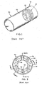
- Figs. 1 and 2 designated “Prior Art,” illustrate the anastomotic device of U.S. Patent No. 4,766,898 , the disclosure of which is hereby incorporated by reference herein.
- Fig. 1 illustrates an anastomotic device 28 connecting free ends 20, 22 of two tubular tissue members 24, 26.
- Fig. 2 shows one of a pair of ring members 32 having a plurality of slots 34 and apertures 36 about its periphery and a mating prong 38 for matingly corresponding with other ring member.
- Each mating prong 38 carries a plurality of locking slots 43 designed and positioned to mate cooperatively with engaging pawls 42.
- the anastomosis device of the present disclosure is used to join vessel ends in anastomotic surgery and is generally referenced by number 100, and is generally shown in Figs. 3-12.
- the anastomosis device 100 is generally comprised of a first ring member 200 and a second ring member 300.
- First ring member 200 is generally comprised of first outer portion 210 and first inner portion 220.
- Second ring member 300 is generally comprised of second outer portion 310 and second inner portion 320.
- Outer portions 210, 310 are operatively attached to inner portions 220, 320, respectively.
- Outer portions 210, 310 are cylindrical ring-like structures with a length and a diameter and inner portions 220, 320 are ring-like structures with a length and a diameter.
- the diameter of first outer portion 210 is substantially the same as the diameter of second outer portion 310, hereinafter referred to as outer portion diameter D (Fig. 11).
- the diameter of first inner portion 220 is substantially the same as the diameter of second inner portion 320, hereinafter referred to as inner portion diameter d (Fig. 11).
- Inner portions 220, 320 are appropriately sized to fit at least partially within outer portions 210, 310, respectively, thus outer portion diameter D is greater than inner portion diameter d.
- the diameters D of outer portions 210, 320 are sized to fit within the tissue lumen 550 and may also be sized to substantially equal an outer diameter of a surgical device (not shown) used to position such an anastomotic device 100.
- the inner diameters d of inner portions 220, 320 are dimensioned and configured to be slightly smaller than the diameters D of outer portions 210, 310. Such a configuration provides a passageway through the tissue lumen 550.
- First outer portion 210 and second outer portion 310 have lengths L, L' (length of cylinder), respectively.
- Lengths L, L' may have a range of about three centimeters to about four centimeters, and may be longer or shorter depending on the desired support to be provided to the tissue 530, 540 and the desired tissue ingrowth.
- Thicknesses T, T' of first outer portion 210 and second outer portion 310 may be dimensioned and configured to be as thin as possible while still providing support for tissue 530, 540. In a particularly useful embodiment, these thicknesses T, T' allow for outer portions 210, 310 to be flexible.
- Outer portions 210, 310 provide support for the anastomosis along their lengths L, L', respectively. Specifically, site of anastomosis 520 is surrounded by tissue 530, 540 near and adjacent thereto. This tissue 530, 540 is supported by cylindrical outer portions 210, 310, respectively (see Fig. 12). This support provided by the length L, L' of cylindrical outer portions 210, 310 maintains the desired circumference of lumen 550 during healing.
- a plurality of holes 400 is annularly disposed around the perimeter of each outer portion 210, 310.
- Plurality of holes 400 provides a scaffold, which enables tissue 530, 540 near and adjacent anastomosis site 520 to grow therethrough.
- Tissue 530, 540 grows through plurality of holes 400 and naturally attaches to itself on inside of outer portions 210, 310, thus at least partially encapsulating outer portions 210, 310.
- This in-growth of tissue and partial encapsulation of outer portions 210, 310 enhances the strength of the portions of the tissue 530, 540 near anastomosis site 520 and further helps to maintain the circumference of lumen 550 during healing.
- Inner portions 220, 320 are configured and dimensioned to mate with each other via a snap-fit or similar type of locking feature, including a bayonet or turn-lock. In a particularly useful embodiment, it is not necessary to turn the ring members 200, 300 to connect them to each other. Accordingly, when inner portions 220, 320 are mated, first ring member 200 and second ring member 300 are locked together.
- a snap-fit or similar type of locking feature including a bayonet or turn-lock.
- first ring member 200 is inserted into a first tubular structure 500 and second ring member 300 is inserted into a second tubular structure 510.
- first and second ring members 200, 300 are inserted into and join tubular structures 500, 510 are depicted in the illustrations of Figs. 3-8.
- Figs. 9 and 11 show anastomosis device 100 in an unapproximated position
- Figs. 10 and 12 show anastomosis device 100 approximated.
- the tissue of the tubular structures 500, 510 is tied, via a purse-string 600 or similar arrangement, around outer portion 210, 310 of each ring member 200, 300, respectively.
- Ring members 200, 300 are then brought together until inner portions 220, 320 meet and mate with each other.
- inner portions 220, 320 are mated, tubular structures 500, 510 around outer portions 210, 310 of anastomotic device 100 are contiguously positioned and compressed between each ring member 200, 300 (Fig. 8) in a manner that will enable them to grow together permanently into a single lumen 550 (Fig. 12).
- a path through inner portions 220, 320 for bodily fluid to flow through is established when two ring members 200, 300 of anastomotic device 100 are locked together (see Fig. 12).
- Anastomotic device 100 may be fabricated from any bioresorbable polymer or copolymer known to those skilled in the art, so long as the polymer utilized has sufficient strength and possesses the necessary mechanical properties to permit formation. Suitable polymers which may be utilized to form anastomotic device 100 include, but are not limited to, trimethylene carbonate, caprolactone, dioxanone, glycolic acid, lactic acid, glycolide, lactide, homopolymers thereof, copolymers thereof, and combinations thereof. Over time, the tissue 530, 540 surrounding the anastomosis site 520 will heal and the anastomotic device 100 will be at least partially absorbed by and then discharged through the body.
- the two tubular structures 500, 510 will have joined together and produced a continuous and strong lumen 550 for fluid and/or gas to flow through.
- the anastomotic device 100 is partially disintegrable, absorbable or resorbable such that the anastomotic device 100 softens and separates from the body.
- the anastomotic device 100 is then passed through the body with waste.
- the anastomotic device 100 may be constructed to break into a plurality of pieces that are passed through the body separately.
- the anastomotic device 100 may remain in the body from about 14 to about 21 days before it is passed through the body.
Landscapes
- Health & Medical Sciences (AREA)
- Life Sciences & Earth Sciences (AREA)
- Surgery (AREA)
- Molecular Biology (AREA)
- Engineering & Computer Science (AREA)
- Biomedical Technology (AREA)
- Heart & Thoracic Surgery (AREA)
- Medical Informatics (AREA)
- Nuclear Medicine, Radiotherapy & Molecular Imaging (AREA)
- Animal Behavior & Ethology (AREA)
- General Health & Medical Sciences (AREA)
- Public Health (AREA)
- Veterinary Medicine (AREA)
- Materials For Medical Uses (AREA)
- Surgical Instruments (AREA)
- Prostheses (AREA)
Abstract
Description
- The present disclosure relates generally to devices for anastomosing tissue. More particularly, the present disclosure relates to a compression anastomosis device for use in minimally invasive surgical procedures.
- An anastomotic device formed of separate ring members having a plurality of fenestrated projections connected by a separate coupling tube is discussed in
U.S. Pat. No. 3,974,835 . In the anastomotic device disclosed in this patent, the free ends of the tube to be joined are tied to the separate ring members at the fenestrated projections, and the singular coupling tube connects the two ring members to engage the tubular ends in a relationship that will enable them to grow together permanently and thereby approximate the diameter of the outer surface of the tubular member. - A similar device formed of a singular pliable, unitary cylindrical sleeve made of knit fabric is disclosed in
U.S. Pat. No. 4,182,339 . In this patent, the unitary, knit cylindrical sleeve has its ends rolled outwardly upon themselves to form relatively firm ring members in spaced relationship which are then connected to the ends of the tubular members in a configuration that will enable these members to grow together. - The above-referenced patents disclose structure to draw the ends of the tubular members together by either turning or rolling these members inwardly to facilitate healing because they enable the ends to rest in a contiguous relationship. Other techniques involve devices like those disclosed in
U.S. Pat. Nos. 3,496,939 and3,254,650 . - It is desirable that a nonpermanent connector or junction device be used to join the vessel ends in anastomotic surgery since a permanent connector will tend to prevent the changes in diameter which are necessary for the proper functioning of the intestine. Any foreign substance used in anastomotic surgery ideally should partially or completely disintegrate, bio-absorb and/or bio-resorb once the vessel ends have partially or fully healed.
- Compression anastomotic devices have been developed in the past for receiving the free ends of anatomic tubular structures to be anastomosed. An example of such an anastomotic device has been developed by Tyco Healthcare LP, and is currently sold under the trademark VALTRAC®. This assembly includes a pair of ring members, each ring member for securement to the free end of each tubular structure to be anastomosed. Each ring member has a connecting structure which mates with the other ring member to connect the ring members.
U.S. Patent No. 4,766,898 issued to Hardy et al. , currently owned by Tyco Healthcare LP, describes the operating features of such an anastomotic device, the contents of which are hereby incorporated by reference in their entirety. - The present disclosure is directed to an anastomotic device for use in the surgical joining of the free ends of a first and a second tubular structure to be anastomosed. The device generally includes a first and a second ring member, each of which is secured to a free end of a tubular structure. Each ring member includes a cylindrical outer portion (first outer portion and second outer portion) and an inner portion (first inner portion and second inner portion) which are operatively attached to each other (i.e., first outer portion is operatively attached to first inner portion; second outer portion is operatively attached to second inner portion). The outer portions are each open ended cylinders and have holes disposed around their perimeters for facilitating tissue growth therethrough. The inner portions, also open ended, have connecting means and are designed to matingly engage one another.
- During an anastomosis procedure, the tubular structures are joined together and secured at their ends. The cylindrical outer portions of the anastomotic device of the present disclosure provide support for the portions of the tubular structures near and adjacent the ends of the tubular structure, thus reducing the likelihood of stricture during healing of the anastomotic tissue. Further, the cylindrical outer portions maintain a generally constant diameter of the tubular structure. Such a lumen of constant diameter is beneficial for fluid and/or gas to flow through. The holes on the outer portion provide a scaffold, which enable tissue to grow therethrough. This in-growth of tissue further enhances the strength of the portions of the tissue near the anastomosis.
- In operation, each ring member is inserted into a tubular structure to be anastomosed. The tissue is tied, via a purse-string or similar arrangement, around the outer portion of each ring member. The ring members are then brought together until the inner portions meet and mate with each other, thus locking the ring members together and forming a flow path therethrough. When the inner portions are mated, the tissue around the outer portions of the anastomotic device are contiguously positioned in a manner that will enable them to grow together permanently. The cylindrical outer portions maintain the desired diameter of the lumen during healing. The holes on the outer portion provide a scaffold for tissue to grow into, thus strengthening the anastomosis site and contiguous areas.
- Over time, the tissue surrounding the anastomosis site will heal and the anastomotic device will be absorbed by and discharged through the body. Once healing is complete, the two tubular structures will have joined together and produced a continuous and strong lumen. Generally, the anastomotic device may remain in the body from about 14 to about 21 days before it is discharged.
- As mentioned above, the anastomosis device will be constructed of a bioabsorbable material. The anastomosis device may comprise bioabsorbable polymeric resin such as, for example, a copolymer of polylactic acid (PLA) and polyglycolic acid (PGA). The relative proportion of the components may be chosen to suit the surgical application. For example, under identical processing conditions, polyglycolic acid is typically the stronger of the two components and more crystalline. However, polyglycolic acid is more rapidly absorbed by body tissue. Hence for surgical applications where it is desired to maintain the implant strength over a longer period of time, the fiber will typically contain more polylactic acid. The fibers can be fibers of the type used in manufacturing suture material. Additionally, several other materials for forming this device are disclosed in
U.S. Patent No. 3,297,033 and are referred to as poly-hydroxyacetic ester and lactide co-polymers, the entire contents of which are incorporated by reference herein. The materials disclosed in the above-referenced patent constitute a partial list of possible materials as molded surgical articles made from a wide range of glycolide /lactide copolymers have been known and utilized for many years. - The length of the cylindrical outer portion may be in the range of about three centimeters to about four centimeters, but may be longer or shorter depending on the desired support to be provided to the tissue and the desired tissue ingrowth. This length provides a desirable amount of support to help resist the tubular structure from stricture and it also helps to maintain the diameter of the lumen during healing.
- The outer portions may have a relatively thin wall thickness. Such a minimal wall thickness, while still providing support for tissue, may make the outer cylindrical portions flexible. Since the thickness of the walls corresponds to the depth of the holes around their perimeters, a minimal wall thickness would also facilitate the growth of tissue therethrough.
- The inner diameter of the first inner portion is substantially the same as the inner diameter of the second inner portion. The outer diameter of the first outer portion is substantially the same as the outer diameter of the second outer portion which is approximately equal to the inner diameter of the tubular vessel to be anastomosed. Accordingly, the anastomotic device can be designed to fit into any suitable tubular vessel.
- In one embodiment, the outer portions are at least partially comprised of a mesh-like material.
- Embodiments of the present disclosure are described hereinbelow with reference to the drawings wherein:
- FIGS. 1 and 2 are prior art figures of an anastomotic device;
- FIGS. 3-8 are perspective views of the anastomotic device of the present disclosure illustrated at different stages of the process by which the first and second ring members are inserted into and join tubular structures;
- FIG. 9 is an enlarged view of the first and second ring members illustrated in an unmated arrangement;
- FIG. 10 is an enlarged view of the first and second ring members illustrated in a mated arrangement;
- FIG. 11 is a cross-section view of the first and second ring members inserted into tubular structures illustrated in an unmated arrangement; and
- FIG. 12 is a cross-section view of the first and second ring members inserted into tubular structures illustrated in a mated arrangement.
- Figs. 1 and 2, designated "Prior Art," illustrate the anastomotic device of
U.S. Patent No. 4,766,898 , the disclosure of which is hereby incorporated by reference herein. Fig. 1 illustrates ananastomotic device 28 connecting free ends 20, 22 of twotubular tissue members ring members 32 having a plurality ofslots 34 andapertures 36 about its periphery and amating prong 38 for matingly corresponding with other ring member. Eachmating prong 38 carries a plurality of lockingslots 43 designed and positioned to mate cooperatively with engagingpawls 42. Whenring members 32 are joined, asingle device 30 is formed and has a substantially toroidal shape. - The anastomosis device of the present disclosure is used to join vessel ends in anastomotic surgery and is generally referenced by
number 100, and is generally shown in Figs. 3-12. As best shown in Figs. 3 and 9, theanastomosis device 100 is generally comprised of afirst ring member 200 and asecond ring member 300.First ring member 200 is generally comprised of firstouter portion 210 and firstinner portion 220.Second ring member 300 is generally comprised of secondouter portion 310 and secondinner portion 320.Outer portions inner portions -
Outer portions inner portions outer portion 210 is substantially the same as the diameter of secondouter portion 310, hereinafter referred to as outer portion diameter D (Fig. 11). The diameter of firstinner portion 220 is substantially the same as the diameter of secondinner portion 320, hereinafter referred to as inner portion diameter d (Fig. 11).Inner portions outer portions outer portions tissue lumen 550 and may also be sized to substantially equal an outer diameter of a surgical device (not shown) used to position such ananastomotic device 100. Desirably, the inner diameters d ofinner portions outer portions tissue lumen 550. - First
outer portion 210 and secondouter portion 310 have lengths L, L' (length of cylinder), respectively. Lengths L, L' may have a range of about three centimeters to about four centimeters, and may be longer or shorter depending on the desired support to be provided to thetissue outer portion 210 and second outer portion 310 (Figs. 10 and 11), respectively, may be dimensioned and configured to be as thin as possible while still providing support fortissue outer portions Outer portions anastomosis 520 is surrounded bytissue tissue outer portions outer portions lumen 550 during healing. - A plurality of
holes 400 is annularly disposed around the perimeter of eachouter portion holes 400 provides a scaffold, which enablestissue adjacent anastomosis site 520 to grow therethrough.Tissue holes 400 and naturally attaches to itself on inside ofouter portions outer portions outer portions tissue anastomosis site 520 and further helps to maintain the circumference oflumen 550 during healing. -
Inner portions ring members inner portions first ring member 200 andsecond ring member 300 are locked together. An example of similar matingly corresponding locking features are disclosed inU.S. Patent No. 4,766,898 issued to Hardy et al. , the contents of which are hereby incorporated by reference in their entirety. - In operation,
first ring member 200 is inserted into a firsttubular structure 500 andsecond ring member 300 is inserted into a secondtubular structure 510. Several stages of the process by which first andsecond ring members tubular structures show anastomosis device 100 in an unapproximated position, and Figs. 10 and 12show anastomosis device 100 approximated. The tissue of thetubular structures string 600 or similar arrangement, aroundouter portion ring member Ring members inner portions inner portions tubular structures outer portions anastomotic device 100 are contiguously positioned and compressed between eachring member 200, 300 (Fig. 8) in a manner that will enable them to grow together permanently into a single lumen 550 (Fig. 12). Further, a path throughinner portions ring members anastomotic device 100 are locked together (see Fig. 12). -
Anastomotic device 100 may be fabricated from any bioresorbable polymer or copolymer known to those skilled in the art, so long as the polymer utilized has sufficient strength and possesses the necessary mechanical properties to permit formation. Suitable polymers which may be utilized to formanastomotic device 100 include, but are not limited to, trimethylene carbonate, caprolactone, dioxanone, glycolic acid, lactic acid, glycolide, lactide, homopolymers thereof, copolymers thereof, and combinations thereof. Over time, thetissue anastomosis site 520 will heal and theanastomotic device 100 will be at least partially absorbed by and then discharged through the body. Once healing is complete, the twotubular structures strong lumen 550 for fluid and/or gas to flow through. In a particularly useful embodiment, theanastomotic device 100 is partially disintegrable, absorbable or resorbable such that theanastomotic device 100 softens and separates from the body. Theanastomotic device 100 is then passed through the body with waste. Theanastomotic device 100 may be constructed to break into a plurality of pieces that are passed through the body separately. Theanastomotic device 100 may remain in the body from about 14 to about 21 days before it is passed through the body. - While the above description contains many specifics, these specifics should not be construed as limitations on the scope of the present disclosure, but merely as exemplifications of preferred embodiments thereof. Those skilled in the art will envision many other possible variations that are within the scope and spirit of the present disclosure.
Claims (10)
- An anastomotic device for use in the surgical joining of a first free end of a first tubular structure and a second free end of a second tubular structure to be anastomosed, the anastomotic device comprising:a first ring member for securement to the first free end of first tubular structure, the first ring member includinga first inner portion having connecting means disposed thereon, anda first outer portion having a length and a thickness, the first outer portion being substantially cylindrically shaped, having open ends and having a plurality of holes disposed therethrough, the plurality of holes providing a scaffold which facilitates tissue to grow through the first outer portion, the first outer portion being operatively attached to the first inner portion; anda second ring member for securement to the second free end of second tubular structure, second ring member includinga second inner portion having connecting means disposed thereon for cooperatively mating with first inner portion, anda second outer portion having a length and a thickness, the second outer portion being substantially cylindrically shaped, having open ends and having plurality of holes disposed therethrough, the plurality of holes providing a scaffold which facilitates tissue to grow through the second outer portion, the second outer portion being operatively attached to the second inner portion.
- The anastomotic device according to claim 1, wherein the length of the first outer portion is between about three centimeters and about four centimeters.
- The anastomotic device according to claim 1 or 2, wherein the length of the second pouter portion is between about three centimeters and about four centimeters.
- The anastomotic device according to claim 1, 2 or 3, wherein the first ring member and the second ring member are made of a bioabsorbable material.
- The anastomotic device according to any one of the preceding claims, wherein the length of the first outer portion and the length of the second outer portion are configured and dimensioned to resist stricture of the first tubular structure and the second tubular structure when the first inner portion and the second inner portion are mated.
- The anastomotic device according to any one of the preceding claims and so constructed that the first ring member locks with the second ring member when the first inner portion is caused matingly to co-operate with the second inner portion.
- The anastomotic device according to any one of the preceding claims, wherein the first inner portion and the second inner portion, when mated with each other, form a flow path through the anastomotic device.
- The anastomotic device according to any one of the preceding claims, wherein an inside diameter of the first inner portion is substantially the same as an inside diameter of the second inner portion.
- The anastomotic device of any one of the preceding claims, wherein the first ring member and the send ring member are comprised of a mesh-like material.
- A surgical device for anastomosing two tubular structures comprising:a first ring member, the first ring member having a cylindrical first outer portion operatively attached to a first inner portion, the cylindrical first outer portion having at last e a partially hollow shaft with open ends and a plurality of holes disposed through the shaft, the plurality of holes facilitates tissue growth through the cylindrical first outer portion, the first inner portion having first connecting means and being disposed at least partially within the cylindrical first outer portion; anda second ring member, the second ring member having a cylindrical second outer portion operatively attached to a second inner portion, the cylindrical second outer portion having at least a partially hollow shaft with open ends and a plurality of holes disposed through the shaft, the plurality of holes facilitates tissue growth through the cylindrical second outer portion, the second inner portion having second connecting means for connecting to the fist connecting means and being disposed at least partially within the cylindrical second outer portion,whereby the first ring member is inserted into a first tubular structure, the second ring member is inserted into a second tubular structure, the first tubular structure is tied around the cylindrical first outer portion, the second tubular structure is tied around the cylindrical second outer portion, and the first ring member is connected to the second ring member via the first connecting means and the second connecting means.
Applications Claiming Priority (1)
| Application Number | Priority Date | Filing Date | Title |
|---|---|---|---|
| US11/304,400 US20070142850A1 (en) | 2005-12-15 | 2005-12-15 | Compression anastomosis device |
Publications (3)
| Publication Number | Publication Date |
|---|---|
| EP1797831A2 true EP1797831A2 (en) | 2007-06-20 |
| EP1797831A3 EP1797831A3 (en) | 2007-12-05 |
| EP1797831B1 EP1797831B1 (en) | 2010-06-30 |
Family
ID=37887993
Family Applications (1)
| Application Number | Title | Priority Date | Filing Date |
|---|---|---|---|
| EP06025705A Not-in-force EP1797831B1 (en) | 2005-12-15 | 2006-12-12 | Compression anastomosis device |
Country Status (7)
| Country | Link |
|---|---|
| US (1) | US20070142850A1 (en) |
| EP (1) | EP1797831B1 (en) |
| JP (2) | JP4994799B2 (en) |
| AU (1) | AU2006246476B2 (en) |
| CA (1) | CA2568874C (en) |
| DE (1) | DE602006015151D1 (en) |
| ES (1) | ES2346144T3 (en) |
Cited By (18)
| Publication number | Priority date | Publication date | Assignee | Title |
|---|---|---|---|---|
| EP2380507A1 (en) * | 2010-04-26 | 2011-10-26 | Zhongchen Liu | Sleeve-type fixing method and device for anastomosis for tubular organs such as intestines, stomach, esophagus |
| KR101155417B1 (en) | 2008-10-22 | 2012-06-14 | 이호기 | Blood vessel anastomosing apparatus |
| WO2015023460A1 (en) * | 2013-08-13 | 2015-02-19 | Cryolife, Inc. | Systems and methods for a fluid carrying conduit of a vascular access system |
| CN108143457A (en) * | 2017-12-28 | 2018-06-12 | 兰州西脉记忆合金股份有限公司 | A kind of disposable self-pressurized type bowel anastomosis device kit and application method |
| EP3520716A4 (en) * | 2016-09-29 | 2019-10-09 | Zhejiang University | ANASTOMOSIS STENT OF RESISTABLY AND UNIMOUNTLY COMPRESSABLE INTESTIN |
| WO2019211316A1 (en) * | 2018-05-02 | 2019-11-07 | Fundació Institut D'investigació En Ciències De La Salut Germans Trias I Pujol | A non-everting anastomosis device and uses thereof |
| US10682453B2 (en) | 2013-12-20 | 2020-06-16 | Merit Medical Systems, Inc. | Vascular access system with reinforcement member |
| US10792413B2 (en) | 2008-03-05 | 2020-10-06 | Merit Medical Systems, Inc. | Implantable and removable customizable body conduit |
| US10925710B2 (en) | 2017-03-24 | 2021-02-23 | Merit Medical Systems, Inc. | Subcutaneous vascular assemblies for improving blood flow and related devices and methods |
| US11026704B2 (en) | 2017-03-06 | 2021-06-08 | Merit Medical Systems, Inc. | Vascular access assembly declotting systems and methods |
| CN113143372A (en) * | 2021-05-20 | 2021-07-23 | 上海理工大学 | Degradable pressurized lumen tissue anastomosis stent |
| US11179543B2 (en) | 2017-07-14 | 2021-11-23 | Merit Medical Systems, Inc. | Releasable conduit connectors |
| US11185676B2 (en) | 2011-09-06 | 2021-11-30 | Merit Medical Systems, Inc. | Vascular access system with connector |
| US11331458B2 (en) | 2017-10-31 | 2022-05-17 | Merit Medical Systems, Inc. | Subcutaneous vascular assemblies for improving blood flow and related devices and methods |
| US11383072B2 (en) | 2017-01-12 | 2022-07-12 | Merit Medical Systems, Inc. | Methods and systems for selection and use of connectors between conduits |
| US11413043B2 (en) | 2016-11-10 | 2022-08-16 | Merit Medical Systems, Inc. | Anchor device for vascular anastomosis |
| NL2029264B1 (en) * | 2021-09-28 | 2023-04-04 | Univ Groningen | Device for performing anastomosis |
| US11911585B2 (en) | 2017-07-20 | 2024-02-27 | Merit Medical Systems, Inc. | Methods and systems for coupling conduits |
Families Citing this family (30)
| Publication number | Priority date | Publication date | Assignee | Title |
|---|---|---|---|---|
| SE530213C2 (en) * | 2006-04-21 | 2008-04-01 | Carponovum Ab | Device and method of anastomosis |
| US8876844B2 (en) * | 2006-11-01 | 2014-11-04 | Ethicon Endo-Surgery, Inc. | Anastomosis reinforcement using biosurgical adhesive and device |
| US7850706B2 (en) * | 2007-08-08 | 2010-12-14 | Board Of Trustees Of The University Of Arkansas | Pancreatic-enteric fistulary catheterization system |
| KR100876516B1 (en) * | 2007-08-29 | 2008-12-31 | 대구 손 | Absorbent Vascular Anastomosis Device |
| US20130110140A1 (en) * | 2009-10-30 | 2013-05-02 | National Yang-Ming University | Anastomosis system |
| FR2972919B1 (en) * | 2011-03-22 | 2014-07-04 | Carmat | PROSTHESIS TO ENSURE THE CONNECTION OF ANATOMIC CHANNEL. |
| US20150245839A1 (en) * | 2012-09-18 | 2015-09-03 | Endo Pharmaceuticals Inc. | Urethral anastomosis device and method |
| US20160074041A1 (en) * | 2013-03-14 | 2016-03-17 | Endo Pharmaceuticals Inc. | Urethral anastomosis device and method |
| US11033272B2 (en) | 2013-04-16 | 2021-06-15 | Ethicon Endo-Surgery, Inc. | Methods for partial diversion of the intestinal tract |
| US9364238B2 (en) | 2013-04-16 | 2016-06-14 | Ethicon Endo-Surgery, Inc. | Method and apparatus for joining hollow organ sections in anastomosis |
| KR101480226B1 (en) | 2013-06-10 | 2015-01-07 | 계명대학교 산학협력단 | Tubular organs of anastomosis device |
| CN103519859B (en) * | 2013-10-25 | 2015-12-30 | 杭州铭众生物科技有限公司 | A kind of gastrointestinal tract stapler |
| KR101504540B1 (en) | 2013-11-29 | 2015-03-20 | 주식회사 메타바이오메드 | Vascular anastomoosis device |
| CN106163424B (en) * | 2013-12-27 | 2019-08-20 | 犹他大学研究基金会 | Blood vessel coupling device |
| CN105078535B (en) * | 2015-09-06 | 2018-06-01 | 浙江大学 | Orientation is disintegrated traceable duct jejunum anastomotic scaffold |
| CA2998170C (en) * | 2015-09-15 | 2023-10-03 | Savage Medical, Inc. | Devices and methods for anchoring a sheath in a tissue cavity |
| EP3202338A1 (en) * | 2016-02-05 | 2017-08-09 | CHU de Nice | Anastomotic connector |
| CN105559844B (en) * | 2016-02-26 | 2018-11-30 | 杭州越阡生物科技有限公司 | Anastomosis ring |
| CN105534556B (en) * | 2016-02-26 | 2017-09-29 | 杭州越阡生物科技有限公司 | A kind of intestines and stomach anastomosis ring |
| US11590010B2 (en) | 2017-01-25 | 2023-02-28 | Merit Medical Systems, Inc. | Methods and systems for facilitating laminar flow between conduits |
| US10376265B2 (en) | 2017-01-30 | 2019-08-13 | Ethicon Llc | Non-magnetic fragmentable tissue compression devices |
| US10555735B2 (en) | 2017-01-30 | 2020-02-11 | Ethicon Llc | Tissue compression assemblies with biodegradable interlinks |
| IT201900003299A1 (en) * | 2019-03-07 | 2020-09-07 | Telea Biotech S R L | METHOD OF PREPARATION FOR THE REVITALIZATION OF AN ACELLULAR TISSUE |
| CN110301951B (en) * | 2019-08-09 | 2020-04-03 | 山东省肿瘤防治研究院(山东省肿瘤医院) | Auxiliary supporting device for gastrointestinal tumor surgery anastomat |
| CN111569163B (en) * | 2020-04-08 | 2022-05-31 | 中国人民解放军陆军军医大学第一附属医院 | Rectum anastomosis stoma protection drainage device |
| CN112773439B (en) * | 2021-01-29 | 2022-03-25 | 沈利聪 | Magnetic fallopian tube anastomosis catheter |
| CN112998794B (en) * | 2021-02-25 | 2022-03-11 | 首都医科大学附属北京朝阳医院 | An anastomotic cannula for rapid connection of rat vein replacement |
| CN113413254B (en) * | 2021-08-24 | 2021-11-16 | 南通欣昌减震器有限公司 | Human tubular structure rubber support |
| KR102591522B1 (en) * | 2021-10-12 | 2023-10-19 | 인제대학교 산학협력단 | Artificial blood vessel with adjustable angiorrhaphy region |
| CN119326465B (en) * | 2024-12-24 | 2025-03-04 | 四川大学华西医院 | Gastrointestinal, intestinal or biliary-intestinal anastomosis instrument for bilateral opening |
Citations (3)
| Publication number | Priority date | Publication date | Assignee | Title |
|---|---|---|---|---|
| US4055186A (en) | 1976-02-11 | 1977-10-25 | Leveen Harry H | Anastomosis button |
| WO1981000668A1 (en) | 1979-09-07 | 1981-03-19 | A Jansen | Medical device for connecting two portions of the intestine,ancillary device for use therewith,and method for insertion of an intestinal button suture with the aid of this device |
| US5527324A (en) | 1994-09-07 | 1996-06-18 | Krantz; Kermit E. | Surgical stent |
Family Cites Families (90)
| Publication number | Priority date | Publication date | Assignee | Title |
|---|---|---|---|---|
| US3232089A (en) * | 1961-05-25 | 1966-02-01 | Rene G Le Vaux | Anastomotic clip and elements |
| US3366301A (en) * | 1965-09-07 | 1968-01-30 | Codman & Shurtleff | Instrument for joining blood vessels |
| US3519187A (en) * | 1966-12-06 | 1970-07-07 | Nickolai Nickolajevich Kapitan | Instrument for suturing vessels |
| US3974835A (en) * | 1972-11-30 | 1976-08-17 | Hardy Jr Thomas G | Anastomotic apparatus and method |
| US4182339A (en) * | 1978-05-17 | 1980-01-08 | Hardy Thomas G Jr | Anastomotic device and method |
| US4467804A (en) * | 1980-10-20 | 1984-08-28 | American Cyanamid Company | Anastomotic device |
| US4766898A (en) * | 1980-10-20 | 1988-08-30 | American Cyanamid Company | Anastomotic device |
| US4368736A (en) * | 1980-11-17 | 1983-01-18 | Kaster Robert L | Anastomotic fitting |
| JPS6129720U (en) * | 1984-07-28 | 1986-02-22 | 高砂医科工業株式会社 | Intestinal anastomosis aid |
| US4893622A (en) * | 1986-10-17 | 1990-01-16 | United States Surgical Corporation | Method of stapling tubular body organs |
| US4752024A (en) * | 1986-10-17 | 1988-06-21 | Green David T | Surgical fastener and surgical stapling apparatus |
| US4917114A (en) * | 1986-10-17 | 1990-04-17 | United States Surgical Corporation | Surgical fastener and surgical stapling apparatus |
| JP2553390B2 (en) * | 1987-02-10 | 1996-11-13 | ヴァーソ プロダクツ オーストラリア ピーティワイ.リミテッド | IV cuff mount |
| US4907591A (en) * | 1988-03-29 | 1990-03-13 | Pfizer Hospital Products Group, Inc. | Surgical instrument for establishing compression anastomosis |
| US4931057A (en) * | 1988-03-29 | 1990-06-05 | Pfizer Hospital Products Group, Inc. | Compression anastomosis coupling assembly |
| SE8802904D0 (en) * | 1988-08-16 | 1988-08-16 | Mogens Bugge | DR MOGENS BUGGE'S MAMMARIA HAKE |
| US4899744A (en) * | 1988-12-15 | 1990-02-13 | Tatsuo Fujitsuka | Apparatus for anastomosing digestive tract |
| US4930674A (en) * | 1989-02-24 | 1990-06-05 | Abiomed, Inc. | Surgical stapler |
| US5425739A (en) * | 1989-03-09 | 1995-06-20 | Avatar Design And Development, Inc. | Anastomosis stent and stent selection system |
| JP2611833B2 (en) * | 1989-05-02 | 1997-05-21 | 株式会社ジェイ・エム・エス | Hollow organ anastomosis instrument |
| US5141516A (en) * | 1989-07-26 | 1992-08-25 | Detweiler Mark B | Dissolvable anastomosis stent and method for using the same |
| US5403333A (en) * | 1990-08-28 | 1995-04-04 | Robert L. Kaster | Side-to-end vascular anastomotic staple apparatus |
| US5234447A (en) * | 1990-08-28 | 1993-08-10 | Robert L. Kaster | Side-to-end vascular anastomotic staple apparatus |
| US5222963A (en) * | 1991-01-17 | 1993-06-29 | Ethicon, Inc. | Pull-through circular anastomosic intraluminal stapler with absorbable fastener means |
| US5250058A (en) * | 1991-01-17 | 1993-10-05 | Ethicon, Inc. | Absorbable anastomosic fastener means |
| US6361543B1 (en) * | 1991-05-29 | 2002-03-26 | Sherwood Services Ag | Inflatable devices for separating layers of tissue, and methods of using |
| US5304220A (en) * | 1991-07-03 | 1994-04-19 | Maginot Thomas J | Method and apparatus for implanting a graft prosthesis in the body of a patient |
| US5443198A (en) * | 1991-10-18 | 1995-08-22 | United States Surgical Corporation | Surgical fastener applying apparatus |
| IL100721A (en) * | 1992-01-21 | 1996-12-05 | Milo Simcha | Punch for opening passages between two compartments |
| US5188638A (en) * | 1992-02-06 | 1993-02-23 | Tzakis Andreas G | Apparatus and method for preforming anastomosis fastener securement of hollow organs |
| US5234448A (en) * | 1992-02-28 | 1993-08-10 | Shadyside Hospital | Method and apparatus for connecting and closing severed blood vessels |
| US5425738A (en) * | 1992-04-08 | 1995-06-20 | American Cyanamid Company | Endoscopic anastomosis ring insertion device and method of use thereof |
| US5282810A (en) * | 1992-04-08 | 1994-02-01 | American Cyanamid Company | Surgical anastomosis device |
| US5906625A (en) * | 1992-06-04 | 1999-05-25 | Olympus Optical Co., Ltd. | Tissue-fixing surgical instrument, tissue-fixing device, and method of fixing tissue |
| US5797931A (en) * | 1992-06-04 | 1998-08-25 | Olympus Optical Co., Ltd. | Tissue-fixing surgical instrument, tissue-fixing device, and method of fixing tissues |
| US5658300A (en) * | 1992-06-04 | 1997-08-19 | Olympus Optical Co., Ltd. | Tissue fixing surgical instrument, tissue-fixing device, and method of fixing tissues |
| CA2133687C (en) * | 1992-10-09 | 2007-03-27 | David T. Green | Surgical clip applier |
| US5725538A (en) * | 1992-10-09 | 1998-03-10 | United States Surgical Corporation | Surgical clip applier |
| US5314436A (en) * | 1992-10-30 | 1994-05-24 | Wilk Peter J | Method and apparatus for performing end-to-end anastomoses |
| US6346074B1 (en) * | 1993-02-22 | 2002-02-12 | Heartport, Inc. | Devices for less invasive intracardiac interventions |
| US5797960A (en) * | 1993-02-22 | 1998-08-25 | Stevens; John H. | Method and apparatus for thoracoscopic intracardiac procedures |
| US5431668A (en) * | 1993-04-29 | 1995-07-11 | Ethicon, Inc. | Ligating clip applier |
| US5437684A (en) * | 1993-10-01 | 1995-08-01 | United States Surgical Corporation | Circular anastomosis device |
| US5562690A (en) * | 1993-11-12 | 1996-10-08 | United States Surgical Corporation | Apparatus and method for performing compressional anastomoses |
| US5503635A (en) * | 1993-11-12 | 1996-04-02 | United States Surgical Corporation | Apparatus and method for performing compressional anastomoses |
| DK145593A (en) * | 1993-12-23 | 1995-06-24 | Joergen A Rygaard | Surgical double instrument for performing connection mlm. arteries (end-to-side anastomosis) |
| US5486187A (en) * | 1994-01-04 | 1996-01-23 | Schenck; Robert R. | Anastomosis device and method |
| US5860581A (en) * | 1994-03-24 | 1999-01-19 | United States Surgical Corporation | Anvil for circular stapler |
| US5881943A (en) * | 1994-06-17 | 1999-03-16 | Heartport, Inc. | Surgical anastomosis apparatus and method thereof |
| US5732872A (en) * | 1994-06-17 | 1998-03-31 | Heartport, Inc. | Surgical stapling instrument |
| EP0765137B1 (en) * | 1994-06-17 | 2003-07-30 | Heartport, Inc. | Surgical stapling instrument |
| US6110187A (en) * | 1995-02-24 | 2000-08-29 | Heartport, Inc. | Device and method for minimizing heart displacements during a beating heart surgical procedure |
| US5976159A (en) * | 1995-02-24 | 1999-11-02 | Heartport, Inc. | Surgical clips and methods for tissue approximation |
| US5904697A (en) * | 1995-02-24 | 1999-05-18 | Heartport, Inc. | Devices and methods for performing a vascular anastomosis |
| US5891160A (en) * | 1996-02-23 | 1999-04-06 | Cardiovascular Technologies, Llc | Fastener delivery and deployment mechanism and method for placing the fastener in minimally invasive surgery |
| US6190590B1 (en) * | 1996-02-28 | 2001-02-20 | Impra, Inc. | Apparatus and method for making flanged graft for end-to-side anastomosis |
| US6083234A (en) * | 1996-07-23 | 2000-07-04 | Surgical Dynamics, Inc. | Anastomosis instrument and method |
| US6391039B1 (en) * | 1996-07-23 | 2002-05-21 | United States Surgical Corporation | Anastomosis instrument and method |
| US7169158B2 (en) * | 1996-07-23 | 2007-01-30 | Tyco Healthcare Group Lp | Anastomosis instrument and method for performing same |
| US6440146B2 (en) * | 1996-07-23 | 2002-08-27 | United States Surgical Corporation | Anastomosis instrument and method |
| US5707380A (en) * | 1996-07-23 | 1998-01-13 | United States Surgical Corporation | Anastomosis instrument and method |
| US6024748A (en) * | 1996-07-23 | 2000-02-15 | United States Surgical Corporation | Singleshot anastomosis instrument with detachable loading unit and method |
| US5868763A (en) * | 1996-09-16 | 1999-02-09 | Guidant Corporation | Means and methods for performing an anastomosis |
| US5916226A (en) * | 1997-02-03 | 1999-06-29 | Tozzi; Piergiorgio | Apparatus and method for improved sutureless anastomosis |
| US5944730A (en) * | 1997-05-19 | 1999-08-31 | Cardio Medical Solutions, Inc. | Device and method for assisting end-to-side anastomosis |
| US6056762A (en) * | 1997-05-22 | 2000-05-02 | Kensey Nash Corporation | Anastomosis system and method of use |
| US6338712B2 (en) * | 1997-09-17 | 2002-01-15 | Origin Medsystems, Inc. | Device to permit offpump beating heart coronary bypass surgery |
| US6083238A (en) * | 1997-09-23 | 2000-07-04 | Baxter International Inc. | Apparatus and method for improved aortic incision |
| US6066144A (en) * | 1997-10-07 | 2000-05-23 | Ethicon Endo-Surgery, Inc. | Surgical anastomosis method |
| US6234995B1 (en) * | 1998-11-12 | 2001-05-22 | Advanced Interventional Technologies, Inc. | Apparatus and method for selectively isolating a proximal anastomosis site from blood in an aorta |
| US6159178A (en) * | 1998-01-23 | 2000-12-12 | Heartport, Inc. | Methods and devices for occluding the ascending aorta and maintaining circulation of oxygenated blood in the patient when the patient's heart is arrested |
| US6193734B1 (en) * | 1998-01-23 | 2001-02-27 | Heartport, Inc. | System for performing vascular anastomoses |
| US6562037B2 (en) * | 1998-02-12 | 2003-05-13 | Boris E. Paton | Bonding of soft biological tissues by passing high frequency electric current therethrough |
| US6280460B1 (en) * | 1998-02-13 | 2001-08-28 | Heartport, Inc. | Devices and methods for performing vascular anastomosis |
| US6015416A (en) * | 1998-02-26 | 2000-01-18 | Ethicon Endo-Surgery, Inc. | Surgical anastomosis instrument |
| US6241741B1 (en) * | 1998-03-09 | 2001-06-05 | Corvascular Surgical Systems, Inc. | Anastomosis device and method |
| US6176864B1 (en) * | 1998-03-09 | 2001-01-23 | Corvascular, Inc. | Anastomosis device and method |
| FR2777446B1 (en) * | 1998-04-17 | 2000-12-01 | Perouse Implant Lab | LINK FOR ANASTOMOSIS, FASTENING DEVICE AND IMPLANT COMPRISING SAME |
| US6206913B1 (en) * | 1998-08-12 | 2001-03-27 | Vascular Innovations, Inc. | Method and system for attaching a graft to a blood vessel |
| US6248117B1 (en) * | 1999-04-16 | 2001-06-19 | Vital Access Corp | Anastomosis apparatus for use in intraluminally directed vascular anastomosis |
| US6331158B1 (en) * | 1999-05-04 | 2001-12-18 | Cardiothoracic Systems, Inc. | Surgical retractor apparatus for operating on the heart through an incision |
| US6241743B1 (en) * | 1999-05-13 | 2001-06-05 | Intellicardia, Inc. | Anastomosis device and method |
| US6080173A (en) * | 1999-05-26 | 2000-06-27 | Idx Medical Ltd. | Tissue punching instrument |
| US6197042B1 (en) * | 2000-01-05 | 2001-03-06 | Medical Technology Group, Inc. | Vascular sheath with puncture site closure apparatus and methods of use |
| US6503259B2 (en) * | 2000-12-27 | 2003-01-07 | Ethicon, Inc. | Expandable anastomotic device |
| US7309358B2 (en) * | 2002-03-21 | 2007-12-18 | Warsaw Orthopedic, Inc. | Vertebral body and disc space replacement devices |
| US6769594B2 (en) * | 2002-05-31 | 2004-08-03 | Tyco Healthcare Group, Lp | End-to-end anastomosis instrument and method for performing same |
| US7229428B2 (en) * | 2002-10-23 | 2007-06-12 | Satiety, Inc. | Method and device for use in endoscopic organ procedures |
| US7220237B2 (en) * | 2002-10-23 | 2007-05-22 | Satiety, Inc. | Method and device for use in endoscopic organ procedures |
| US20040186569A1 (en) * | 2003-03-20 | 2004-09-23 | Berry Bret M. | Height adjustable vertebral body and disc space replacement devices |
-
2005
- 2005-12-15 US US11/304,400 patent/US20070142850A1/en not_active Abandoned
-
2006
- 2006-11-16 JP JP2006309835A patent/JP4994799B2/en not_active Expired - Fee Related
- 2006-11-24 CA CA2568874A patent/CA2568874C/en not_active Expired - Fee Related
- 2006-11-30 AU AU2006246476A patent/AU2006246476B2/en not_active Ceased
- 2006-12-12 DE DE602006015151T patent/DE602006015151D1/en active Active
- 2006-12-12 EP EP06025705A patent/EP1797831B1/en not_active Not-in-force
- 2006-12-12 ES ES06025705T patent/ES2346144T3/en active Active
-
2012
- 2012-03-27 JP JP2012070875A patent/JP2012157704A/en active Pending
Patent Citations (3)
| Publication number | Priority date | Publication date | Assignee | Title |
|---|---|---|---|---|
| US4055186A (en) | 1976-02-11 | 1977-10-25 | Leveen Harry H | Anastomosis button |
| WO1981000668A1 (en) | 1979-09-07 | 1981-03-19 | A Jansen | Medical device for connecting two portions of the intestine,ancillary device for use therewith,and method for insertion of an intestinal button suture with the aid of this device |
| US5527324A (en) | 1994-09-07 | 1996-06-18 | Krantz; Kermit E. | Surgical stent |
Cited By (21)
| Publication number | Priority date | Publication date | Assignee | Title |
|---|---|---|---|---|
| US10792413B2 (en) | 2008-03-05 | 2020-10-06 | Merit Medical Systems, Inc. | Implantable and removable customizable body conduit |
| KR101155417B1 (en) | 2008-10-22 | 2012-06-14 | 이호기 | Blood vessel anastomosing apparatus |
| EP2380507A1 (en) * | 2010-04-26 | 2011-10-26 | Zhongchen Liu | Sleeve-type fixing method and device for anastomosis for tubular organs such as intestines, stomach, esophagus |
| US11185676B2 (en) | 2011-09-06 | 2021-11-30 | Merit Medical Systems, Inc. | Vascular access system with connector |
| WO2015023460A1 (en) * | 2013-08-13 | 2015-02-19 | Cryolife, Inc. | Systems and methods for a fluid carrying conduit of a vascular access system |
| US10682453B2 (en) | 2013-12-20 | 2020-06-16 | Merit Medical Systems, Inc. | Vascular access system with reinforcement member |
| EP3520716A4 (en) * | 2016-09-29 | 2019-10-09 | Zhejiang University | ANASTOMOSIS STENT OF RESISTABLY AND UNIMOUNTLY COMPRESSABLE INTESTIN |
| US11413043B2 (en) | 2016-11-10 | 2022-08-16 | Merit Medical Systems, Inc. | Anchor device for vascular anastomosis |
| US11383072B2 (en) | 2017-01-12 | 2022-07-12 | Merit Medical Systems, Inc. | Methods and systems for selection and use of connectors between conduits |
| US11026704B2 (en) | 2017-03-06 | 2021-06-08 | Merit Medical Systems, Inc. | Vascular access assembly declotting systems and methods |
| US11622846B2 (en) | 2017-03-24 | 2023-04-11 | Merit Medical Systems, Inc. | Subcutaneous vascular assemblies for improving blood flow and related devices and methods |
| US10925710B2 (en) | 2017-03-24 | 2021-02-23 | Merit Medical Systems, Inc. | Subcutaneous vascular assemblies for improving blood flow and related devices and methods |
| US11179543B2 (en) | 2017-07-14 | 2021-11-23 | Merit Medical Systems, Inc. | Releasable conduit connectors |
| US11911585B2 (en) | 2017-07-20 | 2024-02-27 | Merit Medical Systems, Inc. | Methods and systems for coupling conduits |
| US12539403B2 (en) | 2017-10-31 | 2026-02-03 | Merit Medical Systems, Inc. | Subcutaneous vascular assemblies for improving blood flow and related devices and methods |
| US11331458B2 (en) | 2017-10-31 | 2022-05-17 | Merit Medical Systems, Inc. | Subcutaneous vascular assemblies for improving blood flow and related devices and methods |
| CN108143457A (en) * | 2017-12-28 | 2018-06-12 | 兰州西脉记忆合金股份有限公司 | A kind of disposable self-pressurized type bowel anastomosis device kit and application method |
| WO2019211316A1 (en) * | 2018-05-02 | 2019-11-07 | Fundació Institut D'investigació En Ciències De La Salut Germans Trias I Pujol | A non-everting anastomosis device and uses thereof |
| CN113143372A (en) * | 2021-05-20 | 2021-07-23 | 上海理工大学 | Degradable pressurized lumen tissue anastomosis stent |
| WO2023055232A1 (en) * | 2021-09-28 | 2023-04-06 | Implican B.V. | Device for performing anastomosis |
| NL2029264B1 (en) * | 2021-09-28 | 2023-04-04 | Univ Groningen | Device for performing anastomosis |
Also Published As
| Publication number | Publication date |
|---|---|
| JP4994799B2 (en) | 2012-08-08 |
| JP2012157704A (en) | 2012-08-23 |
| US20070142850A1 (en) | 2007-06-21 |
| AU2006246476B2 (en) | 2012-04-19 |
| EP1797831A3 (en) | 2007-12-05 |
| EP1797831B1 (en) | 2010-06-30 |
| CA2568874C (en) | 2014-05-13 |
| ES2346144T3 (en) | 2010-10-11 |
| DE602006015151D1 (en) | 2010-08-12 |
| AU2006246476A1 (en) | 2007-07-05 |
| JP2007160081A (en) | 2007-06-28 |
| CA2568874A1 (en) | 2007-06-15 |
Similar Documents
| Publication | Publication Date | Title |
|---|---|---|
| EP1797831B1 (en) | Compression anastomosis device | |
| AU2005296053B2 (en) | Compression anastomosis device and method | |
| US6682540B1 (en) | Apparatus and method for placing multiple sutures | |
| EP0558352B1 (en) | Apparatus for connecting and closing severed blood vessels | |
| US6926724B1 (en) | Visceral anastomotic device and method of using same | |
| CN114191020A (en) | Anastomosis formation using magnetic device with temporary retention member | |
| WO1990008509A1 (en) | Anastomosis device | |
| AU2014241104B2 (en) | Urethral anastomosis device | |
| KR20220018496A (en) | Coronary anastomosis device and related method | |
| CA2393799A1 (en) | Apparatus and method for placing multiple sutures during anastomosis | |
| US9504468B2 (en) | Vascular prosthesis | |
| CN212346617U (en) | Inner clamping ring for tubular tissue anastomat and tubular tissue anastomat | |
| JP2021159093A (en) | Medical equipment and medical equipment set | |
| WO2021199933A1 (en) | Medical instrument and medical instrument set | |
| JP2021159095A (en) | Medical equipment and medical equipment set |
Legal Events
| Date | Code | Title | Description |
|---|---|---|---|
| PUAI | Public reference made under article 153(3) epc to a published international application that has entered the european phase |
Free format text: ORIGINAL CODE: 0009012 |
|
| AK | Designated contracting states |
Kind code of ref document: A2 Designated state(s): AT BE BG CH CY CZ DE DK EE ES FI FR GB GR HU IE IS IT LI LT LU LV MC NL PL PT RO SE SI SK TR |
|
| AX | Request for extension of the european patent |
Extension state: AL BA HR MK YU |
|
| PUAL | Search report despatched |
Free format text: ORIGINAL CODE: 0009013 |
|
| AK | Designated contracting states |
Kind code of ref document: A3 Designated state(s): AT BE BG CH CY CZ DE DK EE ES FI FR GB GR HU IE IS IT LI LT LU LV MC NL PL PT RO SE SI SK TR |
|
| AX | Request for extension of the european patent |
Extension state: AL BA HR MK YU |
|
| 17P | Request for examination filed |
Effective date: 20080521 |
|
| 17Q | First examination report despatched |
Effective date: 20080623 |
|
| AKX | Designation fees paid |
Designated state(s): DE ES FR GB IE IT |
|
| GRAP | Despatch of communication of intention to grant a patent |
Free format text: ORIGINAL CODE: EPIDOSNIGR1 |
|
| GRAS | Grant fee paid |
Free format text: ORIGINAL CODE: EPIDOSNIGR3 |
|
| GRAA | (expected) grant |
Free format text: ORIGINAL CODE: 0009210 |
|
| AK | Designated contracting states |
Kind code of ref document: B1 Designated state(s): DE ES FR GB IE IT |
|
| REG | Reference to a national code |
Ref country code: GB Ref legal event code: FG4D |
|
| REG | Reference to a national code |
Ref country code: IE Ref legal event code: FG4D |
|
| REF | Corresponds to: |
Ref document number: 602006015151 Country of ref document: DE Date of ref document: 20100812 Kind code of ref document: P |
|
| REG | Reference to a national code |
Ref country code: ES Ref legal event code: FG2A Ref document number: 2346144 Country of ref document: ES Kind code of ref document: T3 |
|
| PGFP | Annual fee paid to national office [announced via postgrant information from national office to epo] |
Ref country code: IT Payment date: 20101222 Year of fee payment: 5 |
|
| PLBE | No opposition filed within time limit |
Free format text: ORIGINAL CODE: 0009261 |
|
| STAA | Information on the status of an ep patent application or granted ep patent |
Free format text: STATUS: NO OPPOSITION FILED WITHIN TIME LIMIT |
|
| 26N | No opposition filed |
Effective date: 20110331 |
|
| REG | Reference to a national code |
Ref country code: DE Ref legal event code: R097 Ref document number: 602006015151 Country of ref document: DE Effective date: 20110330 |
|
| PGFP | Annual fee paid to national office [announced via postgrant information from national office to epo] |
Ref country code: ES Payment date: 20111226 Year of fee payment: 6 |
|
| PG25 | Lapsed in a contracting state [announced via postgrant information from national office to epo] |
Ref country code: IT Free format text: LAPSE BECAUSE OF NON-PAYMENT OF DUE FEES Effective date: 20121212 |
|
| REG | Reference to a national code |
Ref country code: ES Ref legal event code: FD2A Effective date: 20140527 |
|
| PG25 | Lapsed in a contracting state [announced via postgrant information from national office to epo] |
Ref country code: ES Free format text: LAPSE BECAUSE OF NON-PAYMENT OF DUE FEES Effective date: 20121213 |
|
| REG | Reference to a national code |
Ref country code: FR Ref legal event code: PLFP Year of fee payment: 10 |
|
| REG | Reference to a national code |
Ref country code: FR Ref legal event code: PLFP Year of fee payment: 11 |
|
| PGFP | Annual fee paid to national office [announced via postgrant information from national office to epo] |
Ref country code: FR Payment date: 20161121 Year of fee payment: 11 Ref country code: GB Payment date: 20161128 Year of fee payment: 11 Ref country code: IE Payment date: 20161123 Year of fee payment: 11 |
|
| GBPC | Gb: european patent ceased through non-payment of renewal fee |
Effective date: 20171212 |
|
| REG | Reference to a national code |
Ref country code: IE Ref legal event code: MM4A |
|
| REG | Reference to a national code |
Ref country code: FR Ref legal event code: ST Effective date: 20180831 |
|
| PG25 | Lapsed in a contracting state [announced via postgrant information from national office to epo] |
Ref country code: IE Free format text: LAPSE BECAUSE OF NON-PAYMENT OF DUE FEES Effective date: 20171212 Ref country code: FR Free format text: LAPSE BECAUSE OF NON-PAYMENT OF DUE FEES Effective date: 20180102 |
|
| PG25 | Lapsed in a contracting state [announced via postgrant information from national office to epo] |
Ref country code: GB Free format text: LAPSE BECAUSE OF NON-PAYMENT OF DUE FEES Effective date: 20171212 |
|
| PGFP | Annual fee paid to national office [announced via postgrant information from national office to epo] |
Ref country code: DE Payment date: 20201119 Year of fee payment: 15 |
|
| REG | Reference to a national code |
Ref country code: DE Ref legal event code: R119 Ref document number: 602006015151 Country of ref document: DE |
|
| PG25 | Lapsed in a contracting state [announced via postgrant information from national office to epo] |
Ref country code: DE Free format text: LAPSE BECAUSE OF NON-PAYMENT OF DUE FEES Effective date: 20220701 |