EP1797457B1 - Electro-optical method for measuring distance and detecting a non-ideal chirp profile - Google Patents
Electro-optical method for measuring distance and detecting a non-ideal chirp profile Download PDFInfo
- Publication number
- EP1797457B1 EP1797457B1 EP05794659.2A EP05794659A EP1797457B1 EP 1797457 B1 EP1797457 B1 EP 1797457B1 EP 05794659 A EP05794659 A EP 05794659A EP 1797457 B1 EP1797457 B1 EP 1797457B1
- Authority
- EP
- European Patent Office
- Prior art keywords
- signal
- distance
- parameters
- radiation
- frequency
- Prior art date
- Legal status (The legal status is an assumption and is not a legal conclusion. Google has not performed a legal analysis and makes no representation as to the accuracy of the status listed.)
- Active
Links
- 238000000034 method Methods 0.000 title claims description 34
- 230000005855 radiation Effects 0.000 claims description 22
- 230000003287 optical effect Effects 0.000 claims description 14
- 238000005259 measurement Methods 0.000 claims description 13
- 230000005540 biological transmission Effects 0.000 claims description 10
- 238000011156 evaluation Methods 0.000 claims description 6
- 238000005457 optimization Methods 0.000 claims description 6
- 230000008859 change Effects 0.000 claims description 4
- 230000005670 electromagnetic radiation Effects 0.000 claims description 4
- 238000005070 sampling Methods 0.000 claims description 4
- 238000012545 processing Methods 0.000 claims description 3
- 238000007476 Maximum Likelihood Methods 0.000 claims description 2
- 238000004590 computer program Methods 0.000 claims description 2
- 238000006243 chemical reaction Methods 0.000 claims 1
- 238000004519 manufacturing process Methods 0.000 claims 1
- 230000004044 response Effects 0.000 description 8
- 238000013459 approach Methods 0.000 description 7
- 230000007274 generation of a signal involved in cell-cell signaling Effects 0.000 description 3
- 230000032683 aging Effects 0.000 description 2
- 230000008901 benefit Effects 0.000 description 2
- 239000002131 composite material Substances 0.000 description 2
- 238000002592 echocardiography Methods 0.000 description 2
- 230000000694 effects Effects 0.000 description 2
- 238000001914 filtration Methods 0.000 description 2
- 230000010354 integration Effects 0.000 description 2
- 238000000691 measurement method Methods 0.000 description 2
- 238000012552 review Methods 0.000 description 2
- 238000004088 simulation Methods 0.000 description 2
- 230000003595 spectral effect Effects 0.000 description 2
- 230000003466 anti-cipated effect Effects 0.000 description 1
- 238000004422 calculation algorithm Methods 0.000 description 1
- 238000004364 calculation method Methods 0.000 description 1
- 230000000295 complement effect Effects 0.000 description 1
- 230000003750 conditioning effect Effects 0.000 description 1
- 238000012937 correction Methods 0.000 description 1
- 230000002596 correlated effect Effects 0.000 description 1
- 230000008878 coupling Effects 0.000 description 1
- 238000010168 coupling process Methods 0.000 description 1
- 238000005859 coupling reaction Methods 0.000 description 1
- 230000001419 dependent effect Effects 0.000 description 1
- 238000013461 design Methods 0.000 description 1
- 238000001514 detection method Methods 0.000 description 1
- 238000011161 development Methods 0.000 description 1
- 230000018109 developmental process Effects 0.000 description 1
- 238000012886 linear function Methods 0.000 description 1
- 239000000203 mixture Substances 0.000 description 1
- 230000000737 periodic effect Effects 0.000 description 1
- 230000009467 reduction Effects 0.000 description 1
- 230000009897 systematic effect Effects 0.000 description 1
- 230000009466 transformation Effects 0.000 description 1
Images


Classifications
-
- G—PHYSICS
- G01—MEASURING; TESTING
- G01S—RADIO DIRECTION-FINDING; RADIO NAVIGATION; DETERMINING DISTANCE OR VELOCITY BY USE OF RADIO WAVES; LOCATING OR PRESENCE-DETECTING BY USE OF THE REFLECTION OR RERADIATION OF RADIO WAVES; ANALOGOUS ARRANGEMENTS USING OTHER WAVES
- G01S17/00—Systems using the reflection or reradiation of electromagnetic waves other than radio waves, e.g. lidar systems
- G01S17/02—Systems using the reflection of electromagnetic waves other than radio waves
- G01S17/06—Systems determining position data of a target
- G01S17/08—Systems determining position data of a target for measuring distance only
- G01S17/32—Systems determining position data of a target for measuring distance only using transmission of continuous waves, whether amplitude-, frequency-, or phase-modulated, or unmodulated
- G01S17/34—Systems determining position data of a target for measuring distance only using transmission of continuous waves, whether amplitude-, frequency-, or phase-modulated, or unmodulated using transmission of continuous, frequency-modulated waves while heterodyning the received signal, or a signal derived therefrom, with a locally-generated signal related to the contemporaneously transmitted signal
-
- G—PHYSICS
- G01—MEASURING; TESTING
- G01S—RADIO DIRECTION-FINDING; RADIO NAVIGATION; DETERMINING DISTANCE OR VELOCITY BY USE OF RADIO WAVES; LOCATING OR PRESENCE-DETECTING BY USE OF THE REFLECTION OR RERADIATION OF RADIO WAVES; ANALOGOUS ARRANGEMENTS USING OTHER WAVES
- G01S7/00—Details of systems according to groups G01S13/00, G01S15/00, G01S17/00
- G01S7/48—Details of systems according to groups G01S13/00, G01S15/00, G01S17/00 of systems according to group G01S17/00
- G01S7/491—Details of non-pulse systems
- G01S7/4912—Receivers
- G01S7/4915—Time delay measurement, e.g. operational details for pixel components; Phase measurement
-
- G—PHYSICS
- G01—MEASURING; TESTING
- G01S—RADIO DIRECTION-FINDING; RADIO NAVIGATION; DETERMINING DISTANCE OR VELOCITY BY USE OF RADIO WAVES; LOCATING OR PRESENCE-DETECTING BY USE OF THE REFLECTION OR RERADIATION OF RADIO WAVES; ANALOGOUS ARRANGEMENTS USING OTHER WAVES
- G01S7/00—Details of systems according to groups G01S13/00, G01S15/00, G01S17/00
- G01S7/48—Details of systems according to groups G01S13/00, G01S15/00, G01S17/00 of systems according to group G01S17/00
- G01S7/497—Means for monitoring or calibrating
-
- G—PHYSICS
- G01—MEASURING; TESTING
- G01S—RADIO DIRECTION-FINDING; RADIO NAVIGATION; DETERMINING DISTANCE OR VELOCITY BY USE OF RADIO WAVES; LOCATING OR PRESENCE-DETECTING BY USE OF THE REFLECTION OR RERADIATION OF RADIO WAVES; ANALOGOUS ARRANGEMENTS USING OTHER WAVES
- G01S13/00—Systems using the reflection or reradiation of radio waves, e.g. radar systems; Analogous systems using reflection or reradiation of waves whose nature or wavelength is irrelevant or unspecified
- G01S13/02—Systems using reflection of radio waves, e.g. primary radar systems; Analogous systems
- G01S13/06—Systems determining position data of a target
- G01S13/08—Systems for measuring distance only
- G01S13/32—Systems for measuring distance only using transmission of continuous waves, whether amplitude-, frequency-, or phase-modulated, or unmodulated
- G01S13/34—Systems for measuring distance only using transmission of continuous waves, whether amplitude-, frequency-, or phase-modulated, or unmodulated using transmission of continuous, frequency-modulated waves while heterodyning the received signal, or a signal derived therefrom, with a locally-generated signal related to the contemporaneously transmitted signal
- G01S13/343—Systems for measuring distance only using transmission of continuous waves, whether amplitude-, frequency-, or phase-modulated, or unmodulated using transmission of continuous, frequency-modulated waves while heterodyning the received signal, or a signal derived therefrom, with a locally-generated signal related to the contemporaneously transmitted signal using sawtooth modulation
-
- G—PHYSICS
- G01—MEASURING; TESTING
- G01S—RADIO DIRECTION-FINDING; RADIO NAVIGATION; DETERMINING DISTANCE OR VELOCITY BY USE OF RADIO WAVES; LOCATING OR PRESENCE-DETECTING BY USE OF THE REFLECTION OR RERADIATION OF RADIO WAVES; ANALOGOUS ARRANGEMENTS USING OTHER WAVES
- G01S7/00—Details of systems according to groups G01S13/00, G01S15/00, G01S17/00
- G01S7/02—Details of systems according to groups G01S13/00, G01S15/00, G01S17/00 of systems according to group G01S13/00
- G01S7/35—Details of non-pulse systems
- G01S7/352—Receivers
Definitions
- the invention relates to an electro-optical distance measuring method according to the preamble of claim 1, an electro-optical distance measuring device according to the preamble of claim 9 and a computer program product.
- the approach is to emit frequency-modulated electromagnetic radiation, such as visible or non-visible laser light, to the target to be measured and subsequently to receive one or more echoes from backscattering objects, ideally exclusively from the target to be measured.
- After receiving the superimposed echo signal is superimposed with a mixed signal and thereby reduces the frequency of the signal to be analyzed, so that the device side only a lesser effort is necessary.
- the mixing can take place either as a homodyne method with the transmitted signal or as a heterodyne method with a periodic, in particular harmonic, signal known period.
- the methods differ in that they are mixed with the transmission signal itself or with a harmonic signal having its own frequency.
- the mixture is used to transform the received signal to lower frequencies. Subsequently, from the resulting signal the transit times and thus - at known propagation speed of the radiation used - the distances to the targets to be measured determined.
- the devices used to implement these methods usually use a signal generator as a chirp generator, which imparts a signal to a modulatable radiation source.
- a signal generator as a chirp generator, which imparts a signal to a modulatable radiation source.
- lasers are mostly used as radiation sources.
- For emission and reception optical and transmission optics are used, which is followed by a detector or receiver with subsequent mixer, A / D converter and digital signal processor.
- the mixed signal d (t) is digitized on the finite measurement interval -T / 2 ⁇ t ⁇ T / 2 and stored. From the frequency and possibly the phase information of this signal, the transit times t k are determined, where normally n can be assumed to be small and possibly also known.
- One of the echoes, eg the nth can also come from a fixed and known reference target and become the target distances of the remaining targets calculated from the transit time differences t k - t n and the known distance of the reference target.
- the mixed signal m ( t ) - s ( t - t 0 ) itself can serve as a reference, t 0 then corresponds to the reference distance.
- the transit times t k can be determined directly, although the resolution is still coarse. More accurate results can be obtained by considering the phase information.
- EP 0 834 086 B1 describes an optical FMCW distance measurement method that has accuracy in the range of phase measurement methods with a short measurement time.
- a chirp generator generates, for example, a linearly frequency-modulated signal which is divided into a transmission and reference signal, wherein both signals are multiplied in a quadrature receiver complex with one another.
- FMCW method frequency-modulated continuous emission method
- a time-linear frequency-modulated (swept) signal is emitted and analyzed after reflection at a destination and subsequent reception.
- an intermediate frequency signal is generated in a mixer, which is subjected to a fast Fourier transformation.
- the disclosure document describes DE 100 65 657 A1 Cascaded phase locked loops for linearization of oscillators with strong phase noise.
- the goal is the generation of linear analog frequency ramps. Nevertheless achievable linearity and knowledge of the frequency response remain subject to restrictions that can not be completely avoided, even with a great deal of device-side effort.
- the EP 1 464 982 describes a method for FMCW radars with a non-linear ramp modulated transmission frequency response.
- a linearization of - in the ideal case of the linear chirp quadratic phase function is about 10 ppm, so that this approach from the radar range is not suitable for the high-precision measurements of electro-optical methods.
- the method uses a polynomial approach in which the linear component in the modeling of the transmitter lamp is assumed to be known.
- the phase values are needed for the evaluation, so that a phase unwrapping is required. This approach is thus based on an error-causing simplified modeling and the a-priori knowledge of parameters or the necessary resolution of the phase values for deriving the mopdell parameters.
- An object of the invention is to provide a solution which allows an improved identification and knowledge of the frequency response and / or a reduction or avoidance of the errors or their effects, wherein the (real) received signal is to be used directly for the evaluation.
- Another object of the present invention is to reduce the requirements for the components used while maintaining the same performance or to increase the performance with the same components.
- the additional parameters c j or at least part of the parameters c j are determined by measurements, for example determined during each measurement, whereby this determination can also be made together with all other relevant system parameters and the transit times t k .
- the determination of all unknown parameters thus becomes a (statistical) parameter estimation problem.
- An example of a concrete determination method is the known maximum likelihood method, see, for example, ⁇ 35 in BL van der Waerden: Mathematical Statistics, Springer-Verlag, Berlin, Göttingen, Heidelberg, 1957 , In this case, the unknown parameters in the model signal d (t) according to equation (5 ') (or more generally according to the equations (1), (7), (3), (4) and (5)) - ie A 1 , ..
- ⁇ tot can be realized, for example, simply by counting the zero crossings of the transmission signal; the measurement error is then at most 1 ⁇ 2, which is negligible for most purposes compared to the large phase difference ⁇ tot .
- t a - T / 2
- the knowledge of the actual course of the signal generated by the signal generator or the frequency-modulated radiation emitted by the radiation source basically allows two approaches.
- the non-linear component in the signal can already be anticipated in the signal generation by the signal generator being driven accordingly.
- the Signal generation is thus - for example, in real time - adapted to the actual waveform.
- the knowledge of the current error also allows its compensation in the signal processing and distance calculation.
- Both approaches can also be combined with each other, for example by the signal generator is readjusted to non-linearity up to a certain threshold, while the remaining deviation is accepted and taken into account on the computer side.
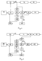
- Fig.1 to Fig.5 purely optical embodiments are shown in which the following Reference numerals are used to identify elements of the purely schematic representations of the device components. Only the homodyne variant is shown. But there are also heterodyne variants and devices in the non-optical spectral range, such as in the radar or microwave range, according to the invention realized. For the heterodyne variant, a further signal generator or a further signal output is required, which generates the second signal required for mixing.
- Fig. 1 shows the schematic representation of a first embodiment according to the invention with a mixer MI, in which the electrical signal s (t) of the signal generator SG and the echo signal e (t) of the detector DE are coupled.
- the signal s (t) of the signal generator SG is also used to impose frequency modulation on the radiation generated by the driver and laser TL.
- This optical radiation in the visible or non-visible spectral range is emitted via a transmission optical system SO and, after reflection at one or more targets or objects, is received again via a receiving optical system EO and a detector DE.
- the mixer MI uses both the signal s (t) of the signal generator SG and the signal of the beam generation of the driver and laser TL included in the received radiation.
- the result of the mixer MI is digitized via a low-pass filter TF and an analog-to-digital converter ADC and supplied to the digital signal processor DSP for signal processing.
- the total phase TP is determined by a counter ZA and also fed to the digital signal processor DSP.
- a controller ST controls the signal generator SG, so that a deviation of the signal generation can be compensated by the ideal course.
- the signal s ( t ) generated by the signal generator SG can either be varied by the controller ST in such a way that the actual emission has a linear frequency characteristic or else the error is taken into account purely algorithmically during the evaluation.
- corrections may include the deviation from the ideal behavior and their mathematical consideration can also be combined.
- Via a user interface BS the distance measuring device can be controlled.
- Fig.2 the schematic representation of a second embodiment according to the invention with a mixer MI with optically detected signal and a counter ZA for the total phase TP.
- the signal s (t) of the signal generator SG is not fed directly to the mixer MI, but it is the radiation emitted by the driver and laser TL radiation via a beam splitter SD to a second detector DE2, whose output is in turn connected to both the mixer MI and a counter ZA for determining the total phase TP connected.
- This arrangement thus uses in addition to the echo signal e ( t ) a second optically detected signal s ( t - t 0 ), which is guided over an internal path, so that influences of the driver / laser combination TL equally on both signals of the mixer MI impact.
- FIG.1 similar embodiment is in Figure 3 shown as a schematic representation of a third embodiment according to the invention with two mixers, direct electrical signal coupling and a quadrature receiver.
- the signal s ( t ) of the signal generator SG is fed to a first mixer MI1 and a second mixer MI2 with downstream low-pass filters TF and analog-to-digital converters ADC, wherein the signal of the second mixer MI2 is shifted in a 90 ° phase shifter.
- the echo signal e ( t ) of the radiation registered by the detector DE is coupled into the first mixer MI1 as well as into the second mixer MI2, so that overall a quadrature receiver results.
- Figure 4 shows the schematic representation of a second embodiment of Fig.2 similar fourth inventive embodiment with two mixers, optically detected signal s ( t - t 0 ) and a quadrature receiver.
- This fourth embodiment combines the quadrature receiver of the third embodiment of FIG Figure 3 with the optical detection of the signal s ( t - t 0 ) of the second embodiment of the Fig.2 .
- the signal s ( t ) of the signal generator SG is not supplied directly to the quadrature receiver, but the radiation emitted by the driver and laser TL radiation is passed via a beam splitter SD to a second detector DE2, which in turn is connected to the quadrature receiver.
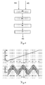
- the Fig.9-11 show numerical examples of the heterodyne case.
- the simulations were also calculated using Matlab, using the same values as in the homodyne case.
- Figure 10 shows how the interference according to equation (9) of the ideal chirp in the heterodyne case. Shown again are the frequency response (top) and mixed and sampled receive signal (bottom).
- the embodiments of the devices can be configured in a heterodyne or homodyne design, with mixers of different types, such as Gilbert cells or scanning mixers, or with replacement of one or more mixers by the sequence of superposition and non-linearity.
Landscapes
- Engineering & Computer Science (AREA)
- Physics & Mathematics (AREA)
- Computer Networks & Wireless Communication (AREA)
- General Physics & Mathematics (AREA)
- Radar, Positioning & Navigation (AREA)
- Remote Sensing (AREA)
- Electromagnetism (AREA)
- Optical Radar Systems And Details Thereof (AREA)
- Radar Systems Or Details Thereof (AREA)
Description
Die Erfindung betrifft ein elektrooptisches Distanzmessverfahren nach dem Oberbegriff des Anspruchs 1, eine elektrooptische Distanzmessvorrichtung nach dem Oberbegriff des Anspruchs 9 und ein Computerprogrammprodukt.The invention relates to an electro-optical distance measuring method according to the preamble of
Im Bereich der elektronischen bzw. elektrooptischen Distanzmessung sind verschiedene Prinzipien und Verfahren bekannt. Der Ansatz besteht darin, frequenzmodulierte elektromagnetische Strahlung, wie z.B. sichtbares oder nicht-sichtbares Laserlicht, auf das zu vermessende Ziel auszusenden und nachfolgend ein oder mehrere Echos von rückstreuenden Objekten, idealerweise ausschliesslich vom zu vermessenden Ziel, zu empfangen. Nach dem Empfang wird das ggf. überlagerte Echosignal mit einem Mischsignal überlagert und dadurch die zu analysierende Frequenz des Signals vermindert, so dass vorrichtungsseitig nur ein geringerer Aufwand notwendig ist. Das Mischen kann dabei entweder als homodynes Verfahren mit dem gesendeten Signal oder als heterodynes Verfahren mit einem periodischen, insbesondere harmonischen, Signal bekannter Periode erfolgen. Somit unterscheiden sich die Verfahren darin, dass mit dem Sendesignal selbst oder mit einem harmonischen Signal mit einer eigenen Frequenz gemischt wird. Die Mischung dient dazu, das empfangene Signal zu tieferen Frequenzen zu transformieren. Nachfolgend werden aus dem resultierenden Signal die Laufzeiten und damit - bei bekannter Ausbreitungsgeschwindigkeit der verwendeten Strahlung - die Distanzen zu den zu vermessenden Zielen bestimmt.In the field of electronic or electro-optical distance measurement, various principles and methods are known. The approach is to emit frequency-modulated electromagnetic radiation, such as visible or non-visible laser light, to the target to be measured and subsequently to receive one or more echoes from backscattering objects, ideally exclusively from the target to be measured. After receiving the superimposed echo signal is superimposed with a mixed signal and thereby reduces the frequency of the signal to be analyzed, so that the device side only a lesser effort is necessary. The mixing can take place either as a homodyne method with the transmitted signal or as a heterodyne method with a periodic, in particular harmonic, signal known period. Thus, the methods differ in that they are mixed with the transmission signal itself or with a harmonic signal having its own frequency. The mixture is used to transform the received signal to lower frequencies. Subsequently, from the resulting signal the transit times and thus - at known propagation speed of the radiation used - the distances to the targets to be measured determined.
Die zur Umsetzung dieser Verfahren verwendeten Vorrichtungen nutzen üblicherweise einen Signalgenerator als Chirp-Generator, der einer modulierbaren Strahlungsquelle ein Signal aufprägt. Im optischen Bereich werden als Strahlungsquellen zumeist Laser eingesetzt. Zur Emission und zum Empfang kommen im optischen Bereich Sende- und Empfangsoptiken zum Einsatz, denen ein Detektor bzw. Empfänger mit nachfolgendem Mischer, A/D-Wandler und digitalem Signal-Prozessor nachgeschaltet ist.The devices used to implement these methods usually use a signal generator as a chirp generator, which imparts a signal to a modulatable radiation source. In the optical field, lasers are mostly used as radiation sources. For emission and reception optical and transmission optics are used, which is followed by a detector or receiver with subsequent mixer, A / D converter and digital signal processor.
Üblicherweise wird vom Signalgenerator als Signal s(t) ein linear frequenzmodulierter Chirp erzeugt: ![]()
![]()
![]()
![]()
![]()
![]()
Im Fall von n Zielen mit relativen Amplituden Ak und Laufzeiten tk (k = 1, ..., n) kann das rauschfreie Echosignal e(t) wie folgt geschrieben werden: ![]()
![]()
Dieses Echosignal e(t) wird detektiert und mit dem Signal m(t) gemischt: 
Durch das Mischen mit m(t) entsteht das Signal ![]()
![]()
Für einen idealen Tiefpass lässt sich die Tiefpassfilterung in (5) gemäss dem Stand der Technik in sehr guter Approximation explizit ausführen, im homodynen Fall zum Beispiel folgt aus der ersten Gleichung in (1) und den Gleichungen (3) bis (5) nach Weglassen der hochfrequenten Terme ![]()
![]()
![]()
![]()
Das gemischte Signal d(t) wird auf dem endlichen Messintervall -T/2≤t≤T/2 digitalisiert und abgespeichert. Aus der Frequenz- und ggf. der Phaseninformation dieses Signals werden die Laufzeiten tk bestimmt, wobei normalerweise n als klein und eventuell auch als bekannt vorausgesetzt werden kann. Eines der Echos, z.B. das n-te, kann auch von einem fixen und bekannten Referenzziel stammen und die Zieldistanzen der restlichen Ziele werden aus den Laufzeitdifferenzen tk - tn und der bekannten Distanz des Referenzziels berechnet. Im homodynen Fall kann das Mischsignal m(t) - s(t - t 0) selber als Referenz dienen, t 0 entspricht dann der Referenzdistanz.The mixed signal d (t) is digitized on the finite measurement interval -T / 2≤ t ≤ T / 2 and stored. From the frequency and possibly the phase information of this signal, the transit times t k are determined, where normally n can be assumed to be small and possibly also known. One of the echoes, eg the nth , can also come from a fixed and known reference target and become the target distances of the remaining targets calculated from the transit time differences t k - t n and the known distance of the reference target. In the homodyne case, the mixed signal m ( t ) - s ( t - t 0 ) itself can serve as a reference, t 0 then corresponds to the reference distance.
Im Fall eines linearen Chirps gemäss Gleichung (1) trägt das k-te Echo die momentane Frequenz 
Im Stand der Technik werden solche oder ähnliche Verfahren beispielsweise in den folgenden Druckschriften beschrieben.In the prior art, such or similar methods are described, for example, in the following publications.
Aus der
In beiden Druckschriften - wie auch in anderen Lösungen des Stands der Technik - wird für die Auswertung ein bekannter, von der Gerätealterung unabhängiger und zeitlich linearer Verlauf der Modulationsfrequenz f(t) vorausgesetzt. Sowohl die Bedingung der Bekanntheit als auch der Alterungsunabhängigkeit und der Linearität sind vorrichtungsseitig nicht oder nur unter grossem Aufwand in der erforderlichen Genauigkeit zu realisieren.In both documents - as well as in other solutions of the prior art - a known, independent of the device aging and temporally linear course of the modulation frequency f ( t ) is assumed for the evaluation. Both the condition of awareness as well as the aging independence and the linearity can not be realized device-side or only with great effort in the required accuracy.
So beschreibt beispielsweise die Offenlegungsschrift
Einen Chirp mit vorgegebenem Frequenzverlauf (z.B. linear) zu erzeugen, ist somit technisch aufwendig und grundsätzlich auch nicht beliebig exakt und stabil möglich. Die auftretenden Abweichungen des Sendesignals vom idealen Verhalten verursachen systematische Messfehler.To produce a chirp with a given frequency profile (for example, linear) is thus technically complex and, in principle, not arbitrary exactly and stably possible. The occurring deviations of the transmission signal from the ideal behavior cause systematic measurement errors.
Die
Eine Aufgabe der Erfindung besteht darin, eine Lösung bereitzustellen, die eine verbesserte Identifizierung und Kenntnis des Frequenzverlaufs und/oder eine Verringerung bzw. Vermeidung der Fehler oder deren Auswirkungen erlaubt, wobei das (reelle) Empfangssignal direkt zur Auswertung genutzt werden soll.An object of the invention is to provide a solution which allows an improved identification and knowledge of the frequency response and / or a reduction or avoidance of the errors or their effects, wherein the (real) received signal is to be used directly for the evaluation.
Eine weitere Aufgabe der vorliegenden Erfindung ist es, bei gleichbleibender Leistung die Anforderungen an die verwendeten Komponenten zu verringern bzw. bei gleichbleibenden Komponenten die Leistung zu erhöhen.Another object of the present invention is to reduce the requirements for the components used while maintaining the same performance or to increase the performance with the same components.
Diese Aufgaben werden durch die Gegenstände des Anspruchs 1 bzw. 9 oder der abhängigen Ansprüche gelöst bzw. die Lösungen weitergebildet.These objects are achieved by the subject-matter of
Die Erfindung beruht darauf, die Phasenfunktion Φ(t) durch endlich viele, auch nichtlineare, Parameter zu modellieren. Dies kann durch eine allgemeine Darstellung mit beliebigen Parametern c1 ,...,cm gemäss ![]()
![]()
![]()
![]()
Die zusätzlichen Parameter cj oder zumindest ein Teil der Parameter cj werden durch Messungen bestimmt, z.B. bei jeder Messung mitbestimmt, wobei diese Bestimmung auch zusammen mit allen anderen relevanten Systemparametern sowie den Laufzeiten tk erfolgen kann. Die Bestimmung aller unbekannten Parameter wird damit zu einem (statistischen) Parameterschätzproblem. Ein Beispiel für ein konkretes Bestimmungsverfahren ist das bekannte Maximum-Likelihood-Verfahren, siehe zum Beispiel §35 in
Im Fall von unkorreliertem normalverteiltem Rauschen, zum Beispiel, entspricht das einer (nichtlinearen) Ausgleichung nach der Methode der kleinsten Quadrate. Damit ist die Bestimmung der Parameter und der Laufzeiten tk - und damit der gesuchten Zieldistanzen - auch im allgemeinen Fall von korreliertem Rauschen auf ein nichtlineares Optimierungsproblem zurückgeführt, für dessen Lösung im Stand der Technik viele, meist iterative, Methoden bekannt sind - zum Beispiel
Die Gewinnung von approximativen Startwerten für die iterative Optimierung kann auch basierend auf Gleichung (6) mit bekannten Methoden erfolgen, wenn die Abweichung des Chirpsignals vom linearen Fall relativ klein ist, was als häufiger Fall anzusehen ist.Obtaining approximate starting values for the iterative optimization can also be based on equation (6) with known methods, if the deviation of the chirp signal from the linear case is relatively small, which is to be regarded as a frequent case.
Zur Verbesserung der Konditionierung des Schätzproblems, d.h. zur Erhöhung der numerischen Stabilität, wird auch die totale Phasenänderung im Sendesignal während eines bekannten Zeitintervalls ta≤t≤tb - z.B. während des Messintervalls, ta =-T/2,tb =T/2 - gemäss Φ tot =Φ(tb )-Φ(ta ) gemessen. Im Fall von Gleichung (7') führt dies auf eine lineare Nebenbedingung ![]()
![]()
![]()
![]()
Die Messung von Φ tot kann zum Beispiel einfach durch Zählen der Nulldurchgänge des Sendesignals realisiert werden; der Messfehler beträgt dann höchstens ½, was für die meisten Zwecke gegenüber der grossen Phasendifferenz Φ tot vernachlässigbar ist. Zum Beispiel ist im Fall der
Ein weiterer Vorteil dieses Ansatzes ist auch, dass kein Quadraturempfänger benötigt wird, wie er beispielsweise in
Die Kenntnis des tatsächlichen Verlaufs des vom Signalgenerator erzeugten Signals bzw. der von der Strahlungsquelle emittierten frequenzmodulierten Strahlung erlaubt grundsätzlich zwei Ansätze. Zum einen kann der nichtlineare Anteil im Signal bereits bei der Signalerzeugung antizipiert werden, indem der Signalgenerator entsprechend angesteuert wird. Die Signalerzeugung wird somit - beispielsweise in Echtzeit - an den tatsächlich erfolgenden Signalverlauf angepasst. Zum anderen erlaubt die Kenntnis des aktuellen Fehlers auch dessen Kompensation bei der Signalverarbeitung und Distanzberechnung. Beide Ansätze können auch miteinander kombiniert werden, z.B. indem der Signalgenerator bis zu einer gewissen Schwelle an Nichtlinearität nachgeregelt wird, während die verbleibende Abweichung in Kauf genommen und rechnerseitig berücksichtigt wird.The knowledge of the actual course of the signal generated by the signal generator or the frequency-modulated radiation emitted by the radiation source basically allows two approaches. On the one hand, the non-linear component in the signal can already be anticipated in the signal generation by the signal generator being driven accordingly. The Signal generation is thus - for example, in real time - adapted to the actual waveform. On the other hand, the knowledge of the current error also allows its compensation in the signal processing and distance calculation. Both approaches can also be combined with each other, for example by the signal generator is readjusted to non-linearity up to a certain threshold, while the remaining deviation is accepted and taken into account on the computer side.
Die erfindungsgemässe Distanzmessvorrichtung bzw. das Distanzmessverfahren wird nachfolgend anhand von in der Zeichnung schematisch dargestellten Ausführungsbeispielen rein beispielhaft näher beschrieben oder erläutert. Im einzelnen zeigen
- Fig.1
- die schematische Darstellung eines ersten erfindungsgemässen Ausführungsbeispiels mit elektrischem Signal als Mischsignal und einem Zähler für die totale Phase;
- Fig.2
- die schematische Darstellung eines zweiten erfindungsgemässen Ausführungsbeispiels mit optisch detektiertem Signal als Mischsignal und einem Zähler für die totale Phase;
- Fig.3
- die schematische Darstellung eines dritten erfindungsgemässen Ausführungsbeispiels mit elektrischem Signal als Mischsignal und einem Quadraturempfänger;
- Fig.4
- die schematische Darstellung eines vierten erfindungsgemässen Ausführungsbeispiels mit optisch detektiertem Signal als Mischsignal und einem Quadraturempfänger;
- Fig.5
- die schematische Darstellung der Erzeugung eines Mischterms durch die Abfolge von Überlagerung und Nichtlinearität;
- Fig.6
- die Darstellung des Frequenzverlaufs und des Empfangssignals für einen perfekten linearen Chirp im homodynen Fall;
- Fig.7
- die Darstellung einer Störung des idealen Chirps mit einem zusätzlichen Term vierter Ordnung im homodynen Fall;
- Fig.8
- die Darstellung von Differenzen von emittierter Frequenz und empfangenem Signal zwischen gestörtem und idealem Chirp im homodynen Fall;
- Fig.9
- die Darstellung des Frequenzverlaufs und des Empfangssignals für den linearen Chirp im heterodynen Fall;
- Fig.10
- die Darstellung einer Störung des idealen Chirps mit einem zusätzlichen Term vierter Ordnung im heterodynen Fall und
- Fig.11
- die Darstellung von Differenzen von emittierter Frequenz und empfangenem Signal zwischen gestörtem und idealem Chirp im heterodynen Fall.
- Fig.1
- the schematic representation of a first embodiment according to the invention with electrical signal as a mixed signal and a counter for the total phase;
- Fig.2
- the schematic representation of a second embodiment according to the invention with optically detected signal as a mixed signal and a counter for the total phase;
- Figure 3
- the schematic representation of a third embodiment according to the invention with electrical signal as a composite signal and a quadrature receiver;
- Figure 4
- the schematic representation of a fourth inventive embodiment with optically detected signal as a composite signal and a quadrature receiver;
- Figure 5
- the schematic representation of the generation of a mixed term by the sequence of superposition and nonlinearity;
- Figure 6
- the representation of the frequency response and the received signal for a perfect linear chirp in the homodyne case;
- Figure 7
- the representation of a perturbation of the ideal chirp with an additional fourth-order term in the homodyne case;
- Figure 8
- the representation of differences of emitted frequency and received signal between disturbed and ideal chirp in the homodyne case;
- Figure 9
- the representation of the frequency response and the received signal for the linear chirp in the heterodyne case;
- Figure 10
- the representation of a disorder of the ideal chirp with an additional fourth order term in the heterodyne case and
- Figure 11
- the representation of differences of emitted frequency and received signal between disturbed and ideal chirp in the heterodyne case.
In den
- ADCADC
- Analog-Digital-WandlerAnalog to digital converter
- BSBS
- BenutzerschnittstelleUser interface
- DEDE
- Detektordetector
- DE1DE1
- Erster DetektorFirst detector
- DE2DE2
- Zweiter DetektorSecond detector
- DSPDSP
- digitaler Signal-Prozessordigital signal processor
- EOEO
- Empfangsoptikreceiving optics
- MIMI
- Mischermixer
- MI1MI1
- Erster MischerFirst mixer
- MI2MI2
- Zweiter MischerSecond mixer
- MSMS
- Mischsignalmixed signal
- NLNL
- Nichtlinearitätnonlinearity
- SDSD
- Strahlteilerbeamsplitter
- SGSG
- Signalgeneratorsignal generator
- SOSO
- Sendeoptiktransmission optics
- STST
- Steuerungcontrol
- TFTF
- Tiefpaßfilterlow pass filter
- TLTL
- Treiber und LaserDrivers and lasers
- UEUE
- Überlagerungoverlay
- ZAZA
- Zählercounter
- 90°90 °
- 90°-Phasenschieber90 ° phase shifter
In
Ein zu
In
In den folgenden
Die
- fs = 10 MHz Abtastfrequenz
- T = 1 ms Chirpdauer
- m = 9980 Anzahl Abtastpunkte
- f 0 = 600 MHz Mittenfrequenz
- B = 100 MHz Chirp-Bandbreite
- d 0 = 0 Signal-Offset
- f s = 10 MHz sampling frequency
- T = 1 ms chirp duration
- m = 9980 number of sampling points
- f 0 = 600 MHz center frequency
- B = 100 MHz chirp bandwidth
- d 0 = 0 signal offset
Für zwei gleich starke Ziele in den Distanzen 4,5 m und 45 m zeigt
In ![]()
![]()
Dargestellt sind in
Die Darstellung von Differenzen von emittierter Frequenz und empfangenem Signal zwischen gestörtem und idealem Chirp im homodynen Fall erfolgt in
Die
In
In
Es versteht sich für den Fachmann, dass die verschiedenen Anordnungen von Komponenten oder Prinzipien miteinander in alternativer oder ergänzender Weise kombiniert werden können. Auch können die Ausführungsbeispiele der Vorrichtungen - wie bereits erwähnt - in heterodyner oder homodyner Bauweise, mit Mischern verschiedener Bauart, wie beispielsweise Gilbert-Zellen oder abtastenden Mischern, oder mit Ersetzung eines oder mehrerer Mischer durch die Abfolge von Überlagerung und Nichtlinearität ausgestaltet werden.It will be understood by those skilled in the art that the various arrangements of components or principles may be combined with each other in an alternative or complementary manner. Also, as already mentioned, the embodiments of the devices can be configured in a heterodyne or homodyne design, with mixers of different types, such as Gilbert cells or scanning mixers, or with replacement of one or more mixers by the sequence of superposition and non-linearity.
Claims (13)
- Electro-optical distance-measuring method comprising the steps• transmission of frequency-modulated optical electromagnetic radiation to n≥1 targets to be surveyed, a chirp as a frequency superposed on the radiation being described by
 • reception of the radiation scattered back by the n≥1 targets,• conversion of the received radiation into at least one received signal with homodyne or heterodyne mixing,• determination of at least one distance to the n≥1 targets from the received signal, characterized in that
at least some of the parameters cj are determined from the received signal, wherein• a total phase change Φ tot = Φ(tb ) - Φ(ta ) in the transmitted signal during a known time interval, in particular the measuring interval, is measured, in particular by counting the passages of the transmitted signal through zero, and• in the signal evaluation for the coefficients c1... , cmo a general secondary condition Φ(tb ;c 1 ,...,cm )-Φ(ta ;c 1 ,...,cm )=Φ tot oro a linear secondary conditionis taken into account.
- Distance-measuring method according to Claim 1, characterized in that at least some of the parameters cj are determined by means of a maximum likelihood method, in particular together with the further system parameters and a transit time tk coordinated with at least one distance.
- Distance-measuring method according to either of the preceding Claims, characterized in that frequency-modulated optical electromagnetic radiation is transmitted to a plurality of targets to be surveyed and, on determination, the distances to the targets to be surveyed are derived from the received signal.
- Distance-measuring method according to any one of the preceding Claims, characterized in that the parameters cj are determined in each measurement, in particular together with further system parameters and/or a transit time tk coordinated with at least one distance.
- Distance-measuring method according to any one of the preceding Claims, characterized in that the phase function according to
 - powers- orthogonal polynomials- wavelets or- discrete delta functions at the sampling points as base functions.
 - Distance-measuring method according to any one of Claims 1 to 5, characterized in that the phase function Φ(t)=Φ(t;c 1 ,...,cm ) is modelled with nonlinear parameters c1 ,...,cm so that the optimization problem to be solved is also nonlinear with respect to the parameters c1 ,..., cm .
- Distance-measuring method according to any one of the preceding Claims, characterized in that, particularly in the case of a small deviation of the chirp from linearity, approximate starting values for the transit times tk are calculated by means of frequency analysis and

- Computer program product with program code, which is stored on a machine-readable medium or is embodied by an electromagnetic wave, for carrying out the method according to any one of Claims 1 to 7, if the program is executed in a computer.
- Electro-optical distance-measuring apparatus for carrying out the distance-measuring method according to any one of Claims 1 to 7, comprising at least• a modulatable optical radiation source (TL) for production and for emission of optical radiation to n≥1 targets to be surveyed,• a signal generator (SG) for modulation of the radiation source (TL), a chirp as a frequency superposed on the radiation being described by
 • a detector (DE, DE1, DE2) for receiving and for converting back-scattered radiation into received signals,• a signal processor, in particular a digital signal processor (DSP), for processing the received signals,• a mixer (MI, MI1, MI2) for carrying out a homodyne or heterodyne mixing procedure, characterized in that
signal generator (SG), detector (DE, DE1, DE2) and signal processor are arranged and designed so that at least some of the parameters cj are determined from the received signal, wherein• a total phase change Φtot = Φ(tb ) - Φ(ta ) in the transmitted signal during a known time interval, in particular the measuring interval, is measured, in particular by counting the passages of the transmitted signal through zero, and• in the signal evaluation for the coefficients c1... , cmo a general secondary condition Φ(tb ;...,c 1,...,cm )-Φ(ta ;c 1,...,cm )=Φ tot oro a linear secondary condition
- Distance-measuring apparatus according to Claim 9, characterized in that signal generator (SG), detector (DE, DE1, DE2) and signal processor are arranged and designed so that the parameters cj are determined in each measurement, in particular together with further system parameters and/or a transit time tk coordinated with at least one distance.
- Distance-measuring apparatus according to either of Claims 9 and 10, characterized by an apparatus for determining the total phase (TP) of the transmitted signal, in particular a counter (ZA).
- Distance-measuring apparatus according to any one of Claims 9 to 11, characterized by a sequence of,• optical or electrical superposition (UE) of the back-scattered radiation with a mixing signal and• a nonlinearity (NL), in particular a quadratic nonlinearity,for producing a mixed term, in particular with a down-circuit low-pass filter (TF).
- Distance-measuring apparatus according to any one of Claims 9 to 12, characterized by a control (ST) which actuates the signal generator (SG) in such a way that deviations of the chirp from a linear frequency profile are compensated, in particular in real time.
Priority Applications (1)
| Application Number | Priority Date | Filing Date | Title |
|---|---|---|---|
| EP05794659.2A EP1797457B1 (en) | 2004-10-09 | 2005-09-29 | Electro-optical method for measuring distance and detecting a non-ideal chirp profile |
Applications Claiming Priority (3)
| Application Number | Priority Date | Filing Date | Title |
|---|---|---|---|
| EP04024127A EP1645890A1 (en) | 2004-10-09 | 2004-10-09 | Method for measuring distances including the determination of the non-ideal characteristics of the chirp |
| PCT/EP2005/054900 WO2006040263A1 (en) | 2004-10-09 | 2005-09-29 | Electro-optical method for measuring distance and detecting a non-ideal chirp profile |
| EP05794659.2A EP1797457B1 (en) | 2004-10-09 | 2005-09-29 | Electro-optical method for measuring distance and detecting a non-ideal chirp profile |
Publications (2)
| Publication Number | Publication Date |
|---|---|
| EP1797457A1 EP1797457A1 (en) | 2007-06-20 |
| EP1797457B1 true EP1797457B1 (en) | 2016-08-24 |
Family
ID=34926928
Family Applications (2)
| Application Number | Title | Priority Date | Filing Date |
|---|---|---|---|
| EP04024127A Withdrawn EP1645890A1 (en) | 2004-10-09 | 2004-10-09 | Method for measuring distances including the determination of the non-ideal characteristics of the chirp |
| EP05794659.2A Active EP1797457B1 (en) | 2004-10-09 | 2005-09-29 | Electro-optical method for measuring distance and detecting a non-ideal chirp profile |
Family Applications Before (1)
| Application Number | Title | Priority Date | Filing Date |
|---|---|---|---|
| EP04024127A Withdrawn EP1645890A1 (en) | 2004-10-09 | 2004-10-09 | Method for measuring distances including the determination of the non-ideal characteristics of the chirp |
Country Status (7)
| Country | Link |
|---|---|
| US (1) | US7671971B2 (en) |
| EP (2) | EP1645890A1 (en) |
| JP (1) | JP4980916B2 (en) |
| CN (1) | CN101036068B (en) |
| AU (1) | AU2005293591B2 (en) |
| CA (1) | CA2583337C (en) |
| WO (1) | WO2006040263A1 (en) |
Families Citing this family (16)
| Publication number | Priority date | Publication date | Assignee | Title |
|---|---|---|---|---|
| FR2912014B1 (en) * | 2007-01-31 | 2011-05-13 | St Microelectronics Sa | ULTRA LARGE BAND PULSE GENERATOR HAVING AN INTEGRATED DIGITAL FILTER EMULATION FUNCTION, AND TRANSMISSION METHOD. |
| JP5062456B2 (en) | 2009-11-27 | 2012-10-31 | トヨタ自動車株式会社 | Radar device |
| JP5581174B2 (en) * | 2010-10-25 | 2014-08-27 | パナソニック株式会社 | Obstacle detection device |
| JP2012093143A (en) * | 2010-10-25 | 2012-05-17 | Panasonic Corp | Obstacle detector |
| KR101465370B1 (en) * | 2013-12-09 | 2014-11-26 | 한국항공우주연구원 | Apparatus and method of generating of direct digital synthesizer chirp signal using phase accumulation polynomial |
| EP3032277B1 (en) | 2014-12-12 | 2021-04-07 | Leica Geosystems AG | Laser tracker |
| CN109283498B (en) * | 2017-07-21 | 2022-07-15 | 北京遥感设备研究所 | Linear frequency modulation pulse signal phase error curve generation method |
| US10534084B2 (en) * | 2017-07-27 | 2020-01-14 | Blackmore Sensors & Analytics, Llc | Method and system for using square wave digital chirp signal for optical chirped range detection |
| DE102018201735A1 (en) * | 2018-02-05 | 2019-08-08 | Carl Zeiss Smt Gmbh | Apparatus and method for determining a distance of a moving object |
| JP7284652B2 (en) * | 2018-08-23 | 2023-05-31 | 株式会社ミツトヨ | Measuring device and method |
| DE102019211832A1 (en) * | 2018-08-23 | 2020-02-27 | Mitutoyo Corporation | MEASURING DEVICE AND MEASURING METHOD |
| JP7169642B2 (en) | 2018-11-28 | 2022-11-11 | 国立研究開発法人産業技術総合研究所 | Optical measuring device and measuring method |
| KR102196035B1 (en) * | 2018-12-26 | 2020-12-29 | (주)미래컴퍼니 | Nonlinear distance error correction method for three dimensional distance measurement camera using pulse phase shift |
| DE102019210074A1 (en) | 2019-07-09 | 2019-10-02 | Carl Zeiss Smt Gmbh | Image sensor and device for determining the position of an optical element, in particular in a microlithographic projection exposure apparatus |
| CN111562564B (en) * | 2020-05-25 | 2022-04-15 | 浙江光珀智能科技有限公司 | Frequency modulation continuous wave laser ranging nonlinear correction device and method |
| CN118377002A (en) * | 2023-01-20 | 2024-07-23 | 华为技术有限公司 | Signal processing method and related device |
Family Cites Families (6)
| Publication number | Priority date | Publication date | Assignee | Title |
|---|---|---|---|---|
| GB9103945D0 (en) * | 1991-02-26 | 1991-06-12 | Philips Electronic Associated | Linearizing a swept-frequency radar |
| DE19521771A1 (en) * | 1995-06-20 | 1997-01-02 | Jan Michael Mrosik | FMCW distance measuring method |
| US5719580A (en) * | 1996-06-06 | 1998-02-17 | Trw Inc. | Method and apparatus for digital compensation of VCO nonlinearity in a radar system |
| JP3719202B2 (en) * | 2001-11-30 | 2005-11-24 | 株式会社村田製作所 | Radar characteristic adjustment method |
| DE10315012B4 (en) * | 2003-04-02 | 2005-05-12 | Eads Deutschland Gmbh | Method for linearization of FMCW radars |
| US7126695B2 (en) * | 2003-10-10 | 2006-10-24 | The Boeing Company | Heterodyne frequency modulated signal demodulator and method of operating the same |
-
2004
- 2004-10-09 EP EP04024127A patent/EP1645890A1/en not_active Withdrawn
-
2005
- 2005-09-29 EP EP05794659.2A patent/EP1797457B1/en active Active
- 2005-09-29 AU AU2005293591A patent/AU2005293591B2/en not_active Ceased
- 2005-09-29 CN CN200580034408XA patent/CN101036068B/en active Active
- 2005-09-29 CA CA2583337A patent/CA2583337C/en not_active Expired - Fee Related
- 2005-09-29 WO PCT/EP2005/054900 patent/WO2006040263A1/en active Application Filing
- 2005-09-29 US US11/576,794 patent/US7671971B2/en active Active
- 2005-09-29 JP JP2007535141A patent/JP4980916B2/en not_active Expired - Fee Related
Also Published As
| Publication number | Publication date |
|---|---|
| EP1645890A1 (en) | 2006-04-12 |
| EP1797457A1 (en) | 2007-06-20 |
| CA2583337A1 (en) | 2006-04-20 |
| AU2005293591A2 (en) | 2006-04-20 |
| JP2008516213A (en) | 2008-05-15 |
| CA2583337C (en) | 2014-07-08 |
| WO2006040263A1 (en) | 2006-04-20 |
| CN101036068A (en) | 2007-09-12 |
| US7671971B2 (en) | 2010-03-02 |
| JP4980916B2 (en) | 2012-07-18 |
| US20090135403A1 (en) | 2009-05-28 |
| CN101036068B (en) | 2010-05-05 |
| AU2005293591A1 (en) | 2006-04-20 |
| AU2005293591B2 (en) | 2009-10-29 |
Similar Documents
| Publication | Publication Date | Title |
|---|---|---|
| EP1797457B1 (en) | Electro-optical method for measuring distance and detecting a non-ideal chirp profile | |
| EP1825293B1 (en) | Method for electronic measurement | |
| EP1825294B1 (en) | Single-channel heterodyne distance measuring method | |
| EP2406659B1 (en) | Distance measurement | |
| DE102017211558A1 (en) | RADAR SYSTEMS AND RELATED METHODS | |
| EP2044459A1 (en) | Angular resolving radar sensor | |
| EP0848829B1 (en) | Rangefinder | |
| DE102008050117A1 (en) | Calibration of a radar unit with device-specific correction curves | |
| DE19922411A1 (en) | Radar measurement of distances, relative speeds between vehicle, obstruction(s) involves computing intercepts of all lines from 2 chirps at 2 frequency positions in distance-speed diagram | |
| DE69834710T2 (en) | RADAR SYSTEM | |
| EP0965052B1 (en) | Sensor system operating method and a sensor system | |
| EP2440949B1 (en) | Method and device for measuring a change in distance | |
| DE102017113730A1 (en) | RADAR FRONTEND WITH HF OSCILLATOR MONITORING | |
| EP3581962A1 (en) | Dual beam fmcw distance measuring method with compensation of a speed-dependent distance measuring fault | |
| DE102010040890A1 (en) | Radar sensor for use in automatic cruise control or pre-crash system in motor car for measuring e.g. distance of preceding car, has evaluation circuits provided for evaluation of reaction of filter circuit to test frequency signal | |
| DE102009027368B4 (en) | Mixer monitoring | |
| DE102008050327A1 (en) | Receiving mixer for homodyne receiving branch of radar unit, has mixer unit mixing cross talk signal with oscillator signal, where cross talk signal is developed based on cross talk effects, and amplifier producing difference signal | |
| EP3418698A1 (en) | Fill level reflectometer with reference reflection | |
| EP4252026A1 (en) | Method for operating a detection device for determining temperature-adjusted distance variables, corresponding detection device, and vehicle having at least one detection device of this kind | |
| DE102023109832B3 (en) | Method for measuring a radial velocity of an object relative to a measuring location | |
| DE102023119216B3 (en) | FMCW procedure | |
| DE19851307B4 (en) | System and method for determining at least one physical quantity | |
| EP1496373B1 (en) | Optical sensor | |
| DE112021006774T5 (en) | RADAR DEVICE AND IN-VEHICLE DEVICE WITH RADAR DEVICE | |
| WO1998038523A1 (en) | Distance and speed measuring method and device |
Legal Events
| Date | Code | Title | Description |
|---|---|---|---|
| PUAI | Public reference made under article 153(3) epc to a published international application that has entered the european phase |
Free format text: ORIGINAL CODE: 0009012 |
|
| 17P | Request for examination filed |
Effective date: 20070330 |
|
| AK | Designated contracting states |
Kind code of ref document: A1 Designated state(s): AT BE BG CH CY CZ DE DK EE ES FI FR GB GR HU IE IS IT LI LT LU LV MC NL PL PT RO SE SI SK TR |
|
| DAX | Request for extension of the european patent (deleted) | ||
| 17Q | First examination report despatched |
Effective date: 20120711 |
|
| GRAP | Despatch of communication of intention to grant a patent |
Free format text: ORIGINAL CODE: EPIDOSNIGR1 |
|
| INTG | Intention to grant announced |
Effective date: 20160511 |
|
| GRAS | Grant fee paid |
Free format text: ORIGINAL CODE: EPIDOSNIGR3 |
|
| GRAA | (expected) grant |
Free format text: ORIGINAL CODE: 0009210 |
|
| AK | Designated contracting states |
Kind code of ref document: B1 Designated state(s): AT BE BG CH CY CZ DE DK EE ES FI FR GB GR HU IE IS IT LI LT LU LV MC NL PL PT RO SE SI SK TR |
|
| REG | Reference to a national code |
Ref country code: GB Ref legal event code: FG4D Free format text: NOT ENGLISH |
|
| REG | Reference to a national code |
Ref country code: CH Ref legal event code: EP |
|
| REG | Reference to a national code |
Ref country code: AT Ref legal event code: REF Ref document number: 823571 Country of ref document: AT Kind code of ref document: T Effective date: 20160915 Ref country code: CH Ref legal event code: NV Representative=s name: KAMINSKI HARMANN PATENTANWAELTE AG, LI |
|
| REG | Reference to a national code |
Ref country code: IE Ref legal event code: FG4D Free format text: LANGUAGE OF EP DOCUMENT: GERMAN Ref country code: FR Ref legal event code: PLFP Year of fee payment: 12 |
|
| REG | Reference to a national code |
Ref country code: DE Ref legal event code: R096 Ref document number: 502005015339 Country of ref document: DE |
|
| REG | Reference to a national code |
Ref country code: NL Ref legal event code: FP |
|
| REG | Reference to a national code |
Ref country code: LT Ref legal event code: MG4D |
|
| PG25 | Lapsed in a contracting state [announced via postgrant information from national office to epo] |
Ref country code: FI Free format text: LAPSE BECAUSE OF FAILURE TO SUBMIT A TRANSLATION OF THE DESCRIPTION OR TO PAY THE FEE WITHIN THE PRESCRIBED TIME-LIMIT Effective date: 20160824 Ref country code: LT Free format text: LAPSE BECAUSE OF FAILURE TO SUBMIT A TRANSLATION OF THE DESCRIPTION OR TO PAY THE FEE WITHIN THE PRESCRIBED TIME-LIMIT Effective date: 20160824 Ref country code: IT Free format text: LAPSE BECAUSE OF FAILURE TO SUBMIT A TRANSLATION OF THE DESCRIPTION OR TO PAY THE FEE WITHIN THE PRESCRIBED TIME-LIMIT Effective date: 20160824 |
|
| PG25 | Lapsed in a contracting state [announced via postgrant information from national office to epo] |
Ref country code: SE Free format text: LAPSE BECAUSE OF FAILURE TO SUBMIT A TRANSLATION OF THE DESCRIPTION OR TO PAY THE FEE WITHIN THE PRESCRIBED TIME-LIMIT Effective date: 20160824 Ref country code: PT Free format text: LAPSE BECAUSE OF FAILURE TO SUBMIT A TRANSLATION OF THE DESCRIPTION OR TO PAY THE FEE WITHIN THE PRESCRIBED TIME-LIMIT Effective date: 20161226 Ref country code: LV Free format text: LAPSE BECAUSE OF FAILURE TO SUBMIT A TRANSLATION OF THE DESCRIPTION OR TO PAY THE FEE WITHIN THE PRESCRIBED TIME-LIMIT Effective date: 20160824 Ref country code: ES Free format text: LAPSE BECAUSE OF FAILURE TO SUBMIT A TRANSLATION OF THE DESCRIPTION OR TO PAY THE FEE WITHIN THE PRESCRIBED TIME-LIMIT Effective date: 20160824 Ref country code: GR Free format text: LAPSE BECAUSE OF FAILURE TO SUBMIT A TRANSLATION OF THE DESCRIPTION OR TO PAY THE FEE WITHIN THE PRESCRIBED TIME-LIMIT Effective date: 20161125 Ref country code: BE Free format text: LAPSE BECAUSE OF NON-PAYMENT OF DUE FEES Effective date: 20160930 |
|
| PG25 | Lapsed in a contracting state [announced via postgrant information from national office to epo] |
Ref country code: EE Free format text: LAPSE BECAUSE OF FAILURE TO SUBMIT A TRANSLATION OF THE DESCRIPTION OR TO PAY THE FEE WITHIN THE PRESCRIBED TIME-LIMIT Effective date: 20160824 Ref country code: RO Free format text: LAPSE BECAUSE OF FAILURE TO SUBMIT A TRANSLATION OF THE DESCRIPTION OR TO PAY THE FEE WITHIN THE PRESCRIBED TIME-LIMIT Effective date: 20160824 |
|
| REG | Reference to a national code |
Ref country code: DE Ref legal event code: R097 Ref document number: 502005015339 Country of ref document: DE |
|
| PG25 | Lapsed in a contracting state [announced via postgrant information from national office to epo] |
Ref country code: DK Free format text: LAPSE BECAUSE OF FAILURE TO SUBMIT A TRANSLATION OF THE DESCRIPTION OR TO PAY THE FEE WITHIN THE PRESCRIBED TIME-LIMIT Effective date: 20160824 Ref country code: BG Free format text: LAPSE BECAUSE OF FAILURE TO SUBMIT A TRANSLATION OF THE DESCRIPTION OR TO PAY THE FEE WITHIN THE PRESCRIBED TIME-LIMIT Effective date: 20161124 Ref country code: CZ Free format text: LAPSE BECAUSE OF FAILURE TO SUBMIT A TRANSLATION OF THE DESCRIPTION OR TO PAY THE FEE WITHIN THE PRESCRIBED TIME-LIMIT Effective date: 20160824 Ref country code: PL Free format text: LAPSE BECAUSE OF FAILURE TO SUBMIT A TRANSLATION OF THE DESCRIPTION OR TO PAY THE FEE WITHIN THE PRESCRIBED TIME-LIMIT Effective date: 20160824 Ref country code: SK Free format text: LAPSE BECAUSE OF FAILURE TO SUBMIT A TRANSLATION OF THE DESCRIPTION OR TO PAY THE FEE WITHIN THE PRESCRIBED TIME-LIMIT Effective date: 20160824 |
|
| REG | Reference to a national code |
Ref country code: IE Ref legal event code: MM4A |
|
| PG25 | Lapsed in a contracting state [announced via postgrant information from national office to epo] |
Ref country code: MC Free format text: LAPSE BECAUSE OF FAILURE TO SUBMIT A TRANSLATION OF THE DESCRIPTION OR TO PAY THE FEE WITHIN THE PRESCRIBED TIME-LIMIT Effective date: 20160824 |
|
| PLBE | No opposition filed within time limit |
Free format text: ORIGINAL CODE: 0009261 |
|
| STAA | Information on the status of an ep patent application or granted ep patent |
Free format text: STATUS: NO OPPOSITION FILED WITHIN TIME LIMIT |
|
| PG25 | Lapsed in a contracting state [announced via postgrant information from national office to epo] |
Ref country code: IE Free format text: LAPSE BECAUSE OF NON-PAYMENT OF DUE FEES Effective date: 20160929 |
|
| 26N | No opposition filed |
Effective date: 20170526 |
|
| PG25 | Lapsed in a contracting state [announced via postgrant information from national office to epo] |
Ref country code: SI Free format text: LAPSE BECAUSE OF FAILURE TO SUBMIT A TRANSLATION OF THE DESCRIPTION OR TO PAY THE FEE WITHIN THE PRESCRIBED TIME-LIMIT Effective date: 20160824 Ref country code: LU Free format text: LAPSE BECAUSE OF NON-PAYMENT OF DUE FEES Effective date: 20160929 |
|
| REG | Reference to a national code |
Ref country code: FR Ref legal event code: PLFP Year of fee payment: 13 |
|
| REG | Reference to a national code |
Ref country code: AT Ref legal event code: MM01 Ref document number: 823571 Country of ref document: AT Kind code of ref document: T Effective date: 20160929 |
|
| REG | Reference to a national code |
Ref country code: BE Ref legal event code: MM Effective date: 20160930 |
|
| PG25 | Lapsed in a contracting state [announced via postgrant information from national office to epo] |
Ref country code: AT Free format text: LAPSE BECAUSE OF NON-PAYMENT OF DUE FEES Effective date: 20160929 |
|
| PG25 | Lapsed in a contracting state [announced via postgrant information from national office to epo] |
Ref country code: HU Free format text: LAPSE BECAUSE OF FAILURE TO SUBMIT A TRANSLATION OF THE DESCRIPTION OR TO PAY THE FEE WITHIN THE PRESCRIBED TIME-LIMIT; INVALID AB INITIO Effective date: 20050929 Ref country code: CY Free format text: LAPSE BECAUSE OF FAILURE TO SUBMIT A TRANSLATION OF THE DESCRIPTION OR TO PAY THE FEE WITHIN THE PRESCRIBED TIME-LIMIT Effective date: 20160824 |
|
| PG25 | Lapsed in a contracting state [announced via postgrant information from national office to epo] |
Ref country code: TR Free format text: LAPSE BECAUSE OF FAILURE TO SUBMIT A TRANSLATION OF THE DESCRIPTION OR TO PAY THE FEE WITHIN THE PRESCRIBED TIME-LIMIT Effective date: 20160824 Ref country code: IS Free format text: LAPSE BECAUSE OF FAILURE TO SUBMIT A TRANSLATION OF THE DESCRIPTION OR TO PAY THE FEE WITHIN THE PRESCRIBED TIME-LIMIT Effective date: 20160824 |
|
| REG | Reference to a national code |
Ref country code: FR Ref legal event code: PLFP Year of fee payment: 14 |
|
| PGFP | Annual fee paid to national office [announced via postgrant information from national office to epo] |
Ref country code: NL Payment date: 20190918 Year of fee payment: 15 |
|
| PGFP | Annual fee paid to national office [announced via postgrant information from national office to epo] |
Ref country code: GB Payment date: 20190920 Year of fee payment: 15 |
|
| PGFP | Annual fee paid to national office [announced via postgrant information from national office to epo] |
Ref country code: CH Payment date: 20190919 Year of fee payment: 15 |
|
| REG | Reference to a national code |
Ref country code: CH Ref legal event code: PL |
|
| REG | Reference to a national code |
Ref country code: NL Ref legal event code: MM Effective date: 20201001 |
|
| GBPC | Gb: european patent ceased through non-payment of renewal fee |
Effective date: 20200929 |
|
| PG25 | Lapsed in a contracting state [announced via postgrant information from national office to epo] |
Ref country code: NL Free format text: LAPSE BECAUSE OF NON-PAYMENT OF DUE FEES Effective date: 20201001 |
|
| PG25 | Lapsed in a contracting state [announced via postgrant information from national office to epo] |
Ref country code: CH Free format text: LAPSE BECAUSE OF NON-PAYMENT OF DUE FEES Effective date: 20200930 Ref country code: GB Free format text: LAPSE BECAUSE OF NON-PAYMENT OF DUE FEES Effective date: 20200929 Ref country code: LI Free format text: LAPSE BECAUSE OF NON-PAYMENT OF DUE FEES Effective date: 20200930 |
|
| PGFP | Annual fee paid to national office [announced via postgrant information from national office to epo] |
Ref country code: FR Payment date: 20230928 Year of fee payment: 19 Ref country code: DE Payment date: 20230920 Year of fee payment: 19 |