EP1796574B1 - Self-ligating orthodontic appliance with clip - Google Patents
Self-ligating orthodontic appliance with clip Download PDFInfo
- Publication number
- EP1796574B1 EP1796574B1 EP05769274A EP05769274A EP1796574B1 EP 1796574 B1 EP1796574 B1 EP 1796574B1 EP 05769274 A EP05769274 A EP 05769274A EP 05769274 A EP05769274 A EP 05769274A EP 1796574 B1 EP1796574 B1 EP 1796574B1
- Authority
- EP
- European Patent Office
- Prior art keywords
- archwire
- clip
- post
- appliance
- orthodontic appliance
- Prior art date
- Legal status (The legal status is an assumption and is not a legal conclusion. Google has not performed a legal analysis and makes no representation as to the accuracy of the status listed.)
- Not-in-force
Links
Images


Classifications
-
- A—HUMAN NECESSITIES
- A61—MEDICAL OR VETERINARY SCIENCE; HYGIENE
- A61C—DENTISTRY; APPARATUS OR METHODS FOR ORAL OR DENTAL HYGIENE
- A61C7/00—Orthodontics, i.e. obtaining or maintaining the desired position of teeth, e.g. by straightening, evening, regulating, separating, or by correcting malocclusions
- A61C7/12—Brackets; Arch wires; Combinations thereof; Accessories therefor
- A61C7/28—Securing arch wire to bracket
- A61C7/30—Securing arch wire to bracket by resilient means; Dispensers therefor
-
- A—HUMAN NECESSITIES
- A61—MEDICAL OR VETERINARY SCIENCE; HYGIENE
- A61C—DENTISTRY; APPARATUS OR METHODS FOR ORAL OR DENTAL HYGIENE
- A61C7/00—Orthodontics, i.e. obtaining or maintaining the desired position of teeth, e.g. by straightening, evening, regulating, separating, or by correcting malocclusions
- A61C7/12—Brackets; Arch wires; Combinations thereof; Accessories therefor
- A61C7/28—Securing arch wire to bracket
Definitions
- This invention broadly relates to appliances that are used in the course of orthodontic treatment. More particularly, the present invention relates to a self-ligating orthodontic appliance such as a bracket or molar appliance having a latch that releasably retains an archwire in an archwire slot of the appliance.
- a self-ligating orthodontic appliance such as a bracket or molar appliance having a latch that releasably retains an archwire in an archwire slot of the appliance.
- Orthodontic therapy is a specialized type of treatment within the field of dentistry, and involves movement of malpositioned teeth to orthodontically correct locations. Orthodontic treatment typically enhances the aesthetic appearance of the teeth, particularly in instances when the patient's front teeth are malpositioned or crooked. Orthodontic treatment can also improve the patient's occlusion so that the teeth function better with each other during mastication.
- Braces Many types of orthodontic treatment programs involve the use of a set of tiny appliances and wires that are commonly known collectively as "braces".
- small slotted appliances known as brackets are fixed to the patient's anterior, cuspid and bicuspid teeth, and an archwire is inserted into the slot of each bracket.
- the archwire forms a track to guide movement of the teeth to orthodontically correct locations.
- End sections of the archwires are typically captured in molar appliances that are fixed to the patient's molar teeth.
- a recently introduced self-ligating appliance known as "SMARTCLIP” brand appliance from 3M Unitek Corporation has a latch that comprises two resilient clips, and each clip has a generally "C"-shaped configuration.
- the clips spread open to admit an archwire into an archwire slot of the appliance.
- Each clip is connected to a body of the appliance by a post that extends through the clip, and an outwardly extending base of the appliance helps to retain the clip in place on the post.
- the present invention is directed toward a self ligating orthodontic appliance having a latch that includes at least one clip.
- Each clip is connected to remaining components of the appliance by a post that extends through a recess of the clip.
- Each clip also has at least one protrusion that extends along a side of the post for retaining the clip in place.
- the present invention is directed in one aspect to an orthodontic appliance that comprises a base, a body extending outwardly from the base and an archwire slot extending across the appliance in a generally mesial-distal direction.
- the appliance also includes a post extending outwardly from the body, and a latch for releasably retaining an archwire in the archwire slot.
- the latch comprises a clip with a region next to the archwire slot for receiving the archwire.
- the clip also includes a recess that receives the post, and the recess is in communication with the archwire- receiving region.
- the post includes a side that faces the region.
- the clip also includes at least one protrusion that extends along the side of the post between the region and the recess.
- an orthodontic appliance that comprises a base, a body extending outwardly from the base and an archwire slot extending across the appliance in a generally mesial-distal direction.
- the appliance further comprises a post extending outwardly from the body and a latch for releasably retaining an archwire in the archwire slot.
- the latch comprises a clip with a region next to the archwire slot for receiving an archwire.
- the clip also includes a recess that receives the post, and the recess is in communication with the archwire-receiving region.
- the post includes a side that faces the region.
- the clip also includes two protrusions that extend in opposite directions toward each other along the side of the post.
- the clip of the present invention enables the archwire to be inserted into the archwire-receiving region with less force than might be otherwise expected. Consequently, the practitioner is able to ligate the archwire to the appliance with less force and as a result the procedure is less painful to the patient. This feature is particularly important for patients with teeth that are somewhat mobile due to previous orthodontic therapy since those teeth are known to be more sensitive to pain caused by the pressure of external forces.
- Mesial means in a direction toward the center of the patient's curved dental arch.
- distal means in a direction away from the center of the patient's curved dental arch.
- gingival means in a direction toward the patient's gums or gingiva.
- “Buccolabial” means in a direction toward the patient's lips or cheeks.
- “Lingual” means in a direction toward the patient's tongue.
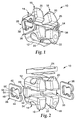
- FIG. 1-8 An orthodontic appliance constructed in accordance with one embodiment of the present invention is illustrated in Figs. 1-8 and is broadly designated by the numeral 10.
- the appliance 10 in this instance is an orthodontic bracket that is adapted to be secured to an enamel surface of a patient's tooth, such as a buccolabial tooth surface.
- the appliance could be a molar appliance, an appliance for attachment to a lingual tooth surface, or any other appliance that is adapted to receive an archwire for controlling movement of the associated tooth during the course of orthodontic therapy.
- the appliance 10 includes a base 12 for bonding the appliance 10 directly to the patient's tooth enamel by the use of an adhesive.
- the base 12 has an outwardly facing concave compound contour that matches the convex compound contour of the patient's tooth surface to which it is bonded.
- the base 12 is provided with grooves, particles, recesses, undercuts, a chemical bond enhancement material or any other material or structure, or any combination of the foregoing that facilitates bonding of the appliance 10 directly to the patient's tooth surface.
- a body 14 extends outwardly from the base 12 in a generally buccolabial direction.
- the body 14 includes a mesial body portion 16 and a distal body portion 18 that is spaced from the mesial body portion 16.
- each of the portions 16, 18 includes an occlusal tiewing 20 and a gingival tiewing 22, although one or more of the tiewings 20, 22 could be omitted if desired.
- the body 14 (including the body portions 16, 18) is integrally connected to the base 12, and the body 14 and the base 12 form a single, unitary component.
- the base and the body are made of a metallic material, the base could be manufactured separately from the body and later welded or brazed to the body during an assembly operation.
- the appliance 10 also includes an archwire slot liner 24 that is fixed to the body portions 16, 18.
- the archwire slot liner 24 defines occlusal, gingival and lingual sides of an archwire slot 26.
- the archwire slot 26 longitudinally extends in a generally mesial-distal direction across the appliance 10, including through a channel of the body portions 16, 18.
- the archwire slot liner 24 is optional and may be omitted. If the archwire slot liner 24 is omitted, the channel of the body portions 16, 18 is made smaller in order to match the cross-sectional area of the archwire and serve as an archwire slot.
- the base 12, the body 14 and the archwire slot liner 24 are preferably similar to the corresponding components of the appliances described in U.S. Patent Nos. 5,439,379 and 5,366,372 .
- the base 12 and the body 14 are made of a transparent monocrystalline ceramic material or a translucent polycrystalline ceramic material such as alumina, and the archwire slot liner 24 is made of a metallic material. Examples of suitable materials and methods for constructing the archwire slot liner 24, as well as suitable methods of attaching the archwire slot liner 24 to the body portions 16, 18 are described in U.S. Patent Nos. 5,358,402 and 5,380,196 .
- Each of the tiewings 20, 22 extends over a recess or notch for receiving a ligature (not shown).
- a ligature (not shown).
- the provision of the tiewings 20, 22 and the use of a ligature are optional and may only be needed in certain instances, such as in instances where the tooth is severely malpositioned during the initial stages of treatment.
- the tiewings 20, 22 and the ligature-receiving recesses are constructed as set out in applicant's copending U.S. Patent Application Serial No. 10/770779, filed February 3, 2004 and entitled "ORTHODONTIC BRACKET WITH REINFORCED TIEWINGS".
- the appliance 10 includes a mesial post 28 and a distal post 30 that are integrally connected to the mesial body portion 16 and the distal body portion 18 respectively.
- the posts 28, 30 extend outwardly in opposite directions away from each other and from the body 14.
- each post 28, 30 extends along a reference axis that is parallel to the longitudinal axis of the archwire slot 26.
- the posts 28, 30 are located in a lingual direction relative to the archwire slot 26.
- the mesial post 28 includes an outermost head 32 and a neck 34 that integrally interconnects the head 32 and the mesial body portion 16.
- the neck 34 has a generally rectangular cross-sectional configuration when considered in reference planes perpendicular to the reference axis along which the post 28 extends or when considered in reference planes generally perpendicular to a mesial-distal axis.
- the occlusal, gingival and lingual sides of the neck 34 in regions along the innermost or distal end of the neck 34 include curved or chamfered sections that are connected to the mesial side of the mesial body portion 16, for enhancing the strength of the connection between the mesial post 28 and the body 14.
- the head 32 of the post 28 has a generally trapezoidal configuration when viewed in a distal direction, or when viewed in reference planes that are perpendicular to the reference axis along which the post 28 extends.
- Fig. 5 also illustrates in dashed lines the cross-sectional shape of the neck 34 for purposes of comparison.
- the height of the neck 34 and the height of the head 32 are essentially the same along the lingual side of the post 28 when considered in directions along an occlusal-gingival reference axis (i.e. along a vertical axis when viewing Figs. 5-8 ).
- the height of the head 32 is greater than the height of the neck 34 when considered in directions along an occlusal-gingival reference axis.
- the head 32 extends outwardly past the neck 34 a certain distance when considered in reference planes perpendicular to a mesial-distal reference axis or when considered in reference planes perpendicular to the reference axis along which the post 28 extends.
- the head 32 extends outwardly past the neck 34 in at least one, and preferably in both directions along an occlusal-gingival reference axis, or in directions along a vertical axis when viewing Figs 5-8 .
- this certain distance is determined by adding the distance that the head 32 extends past the neck 34 in an occlusal direction to the distance that the head 32 extends past the neck 34 in a gingival direction.
- this certain distance decreases as the lingual side of the post 28 is approached and as a third section 46 of the clip 36 (as described below) is approached. This relationship is shown by the dashed lines in Fig. 5 illustrating the occlusal and gingival sides of the neck 34, in comparison to the full lines that depict the occlusal and gingival sides of the head 32. Preferably, this certain distance is zero or approximately zero in regions adjacent the third section 46.
- the archwire slot liner 24 has a rectangular mesial extension that extends over the buccolabial side of the post 28 and is connected to the same by the methods described in U.S. Patent Nos. 5,358,402 and 5,380,196 .
- the archwire slot liner 24 may have a mesial extension that is somewhat "T"-shaped, to match the generally "T"-shaped configuration presented by the neck 34 and the head 32 as depicted in Fig. 3 .
- the mesial extension of the archwire slot liner 24 may be omitted such that the mesial end of the archwire slot liner 28 is flush with the mesial side of the mesial body portion 16.
- the appliance 10 also includes a latch for releasably retaining an archwire in the archwire slot 26.
- the latch includes a mesial clip 36 that is connected to the mesial post 28, and a distal clip 38 that is connected to the distal post 30.
- the mesial clip 36 is omitted from Figs. 3, 4 and 6 for purposes of illustration.
- the mesial clip 36, the neck 34 and an exemplary archwire 40 are shown alone in Figs. 7 and 8 .
- the mesial clip 36 includes an elongated occlusal or first section 42, an elongated second or gingival section 44 and an elongated lingual or third section 46.
- the first and second sections 42, 44 extend in generally parallel directions that lie along a generally buccolabial-lingual reference axis when the clip 36 is relaxed, and the third section 46 extends in a generally occlusal-gingival direction perpendicular to the direction of extension of the sections 42, 44.
- the third section 46 also integrally connects the first and second sections 42, 44. Additionally, outer ends of the sections 42, 44 are integrally connected to arm portions 48, 50 respectively. A buccolabial edge of each arm portion 42, 44 is smoothly curved in an arc about a mesial-distal reference axis.
- each of the sections 42, 44, 46 extend along the occlusal, gingival and lingual sides of the neck 34 respectively.
- each of the sections 42, 44 includes a somewhat triangular-shaped protrusion that extends along a portion of the buccolabial side of the neck 34.
- a rear (lingual) portion of the first and second sections 42, 44, along with the third section 46 and the protrusions 52 together at least partially define a recess 54 (see Figs. 2 and 8 ) for receiving the neck 34 of the post 28.
- the clip 36 is shown in its normal, relaxed orientation in Figs. 1, 2 , 5 and 7 .
- the arm portions 48, 50 are movable away from each other in order to admit the archwire 40 into the archwire-receiving region 56 when desired.
- the first and second sections 42, 44 deflect outwardly when the clip 36 is opened and bend in respective arcs away from each other in order to enable the arm portions 48, 50 to move apart from each other.
- Fig. 8 is an exemplary illustration showing the clip 36 opened, wherein the arm portions 48, 50 have been moved apart from each other a sufficient distance to permit passage of the archwire 40 into the region 56.
- the protrusions 52 slide across the buccolabial side of the neck 34. However, the protrusions 52 extend inwardly and toward each other a distance sufficient to remain in contact with the buccolabial side of the neck 34 as the clip 36 is opened. As such, the clip 36 remains coupled to the post 28 during such opening movements.
- the region 56 is somewhat larger than the cross-section of the archwire 40 in directions along both an occlusal-gingival reference axis as well as along a buccolabial-lingual reference axis, in order to avoid firm contact between the clip 36 and the archwire 40.
- the spaces between the clip 36 and the archwire 40 provide what is often referred to as "passive" ligation.
- the clip 36 (including the first and second sections 42, 44) is sufficiently stiff to retain the archwire 40 in the archwire slot 26 during the course of treatment so long as the forces exerted by the archwire 40 on the appliance 10 are below a certain minimum value in a generally buccolabial direction (more particularly, in a direction opposite to the direction of insertion of the archwire 40 into the archwire slot 26).
- the first and second sections 42, 44 deflect outwardly and the arm portions 48, 50 move apart from each other to open the clip 36 and release the archwire 40 from the archwire slot 26. Further details regarding such forces are described in the aforementioned U.S. Patent Nos. 6,302,688 and 6,582,226 .
- the clip 36 is substantially identical to the clip 38 and the post 28 is substantially identical in mirror image to the post 30.
- the latch comprising the clips 36, 38, preferably releases the archwire 40 from the archwire slot 26 in a generally buccolabial direction whenever the archwire 40 exerts a force in the same direction on the appliance 10 that is in the range of about 0.2 lb (0.1 kg) to about 11 lb (5 kg), more preferably in the range of about 0.4 lb (0.2 kg) to about 5.5 lb (2.5 kg), and most preferably in the range of about 0.75 lb (0.34 kg) to about 3.0 lb (1.4 kg).
- the minimum value is sufficiently high to prevent the archwire from unintentionally releasing from the archwire slot 26 during the normal course of orthodontic treatment.
- the archwire 40 can exert forces on the appliance 10 sufficient to carry out the treatment program and move the associated teeth as desired.
- the minimum value for self-release (i.e., self-opening) of the latch is substantially less than the force required in the same direction to debond the appliance 10 from the associated tooth.
- the minimum value for self-release of the latch is preferably less than about one-half of the force required in the same direction to debond the appliance 10 from the associated tooth. For example, if the expected bond strength of the adhesive bond between the appliance 10 and the associated tooth is 16 lbs (7.2 kg) in a buccolabial direction, the latch is constructed to self-release the archwire 40 whenever the archwire 40 exerts a force in the same buccolabial direction on the appliance 10 that is somewhat greater than about 8 lbs (3.6 kg).
- a section of archwire is selected having an area in longitudinally transverse sections that is complemental to (i.e., substantially fills) the cross-sectional area of the archwire slot 32.
- a sling is constructed and is connected to the archwire section at locations closely adjacent, but not in contact with the heads of the posts 28, 30 including the head 32.
- the sling is welded or brazed to the archwire section.
- the sling is pulled away from the appliance 10 while the appliance 10 is held in a stationary position, taking care to ensure that the longitudinal axis of the archwire section does not tip relative to the longitudinal axis of the archwire slot 26.
- the force to release the latch may be determined by use of an Instron testing apparatus connected to the sling, using a crosshead speed of 0.5 in/min (1.3 cm/min).
- a shaker apparatus such as Model 300 from APS Dynamics of Carlsbad, California
- a force transducer such as model 208C01 from PCB of Buffalo, New York
- the distance between the opposed ends of the arm portions 48, 50 is less than the overall occlusal-gingival dimension of the smallest archwire 40 expected to be used during the course of treatment.
- the archwire 40 need not fill the archwire slot 26 and flatly engage the wall portions defining the archwire slot 26 in all instances.
- a somewhat smaller wire, and perhaps an archwire 40 having a circular cross-sectional shape may be used during a portion of the treatment program.
- the distance between the opposed ends of the arm portions 48, 50 is preferably selected so that a variety of archwires of different cross-sectional configurations may be used in connection with the appliance 10.
- the distal clip 38 is substantially identical to the mesial clip 36.
- the clips 36, 38 it is possible to construct the clips 36, 38 somewhat differently to address certain circumstances. For example, if a malpositioned tooth is initially oriented such that its mesial side is rotated in a lingual direction, it may be desirable to increase the stiffness of the mesial clip 36 so that a somewhat greater force is needed to release the archwire 40 from the archwire slot 26 in comparison to the force needed to release the archwire 40 from the distal clip 38. Other options are also possible.
- the spring clips 36, 38 are cut from a flat section of metallic stock material.
- Suitable metallic materials include shape memory alloys such as alloys of nitinol and beta-titanium.
- the clips 36, 38 may be cut from the stock material using a stamping, die cutting, chemical etching, EDM (electrical discharge machining), laser cutting or water jet cutting process.
- the clips 36, 38 could be formed and then heat-treated to set their shapes.
- the clips 36, 38 are made from flat annealed superelastic material (such as nitinol) having a pickled surface.
- Preferred nitinol materials have a nickel content of 55.97% by weight and an A f of 10° ⁇ 5°C.
- the nitinol is cold worked to 37.5% and has a thickness in the range of about 0.012 in. (0.3 mm) to about 0.016 in. (0.4 mm).
- the clips 36, 38 are first cut in a rough cutting EDM process, then cut along their edges for an additional one or more times using an EDM process in order to smooth the edges.
- a laser cutting process or chemical etching process could be used to make the clips 36, 38.
- the clips 36, 38 are constructed so that the longitudinal direction of the clip material, or the principal direction of grain flow of the clip material, is substantially parallel to the direction of extension of the first and second sections 42, 44 (i.e. a generally buccolabial direction in the illustrated embodiment ).
- the clips 36, 38 are tumbled in order to further round their edges.
- An example of a suitable tumbling machine is model LC-600-2+2 from Richwood Industries. Using a small barrel, and a machine speed of 200 rpm, the clips are tumbled for about 2 hours in 500 cc of water and tumbling media.
- An example of suitable tumbling media is a mixture of 500 cc of ceramic media (shaped ACC, type M, size 3/16 X 3/8 (4.7 mm X 9.5 mm)), 25 cc of white alumina powder no. 40, and 25 cc of soap powder compound no. 43, all from Richwood Industries.
- the tumbled clips are then polished for one-half hour in an ultrasonic screen barrel in a tank of solution.
- An example of a suitable solution is 3 liters of deionized water, 3 liters of pickling solution and 0.6 liter of hydrogen peroxide.
- a suitable pickling solution is No. TI121 Pickling Solution from Aya International of Los Angeles, California.
- the archwire slot liner 24 is affixed to the body 14 and the clips 36, 38 are then assembled to the posts 28, 30 respectively.
- the clip 36 is opened by moving the sections 42, 44 in directions away from each other a distance sufficient to clear the head 32 and enable the neck 34 to be received in the recess 54 by moving the clip 36 in a distal direction.
- pressure on the sections 42, 44 is relieved and the clip 36 springs back to its normal, relaxed configuration such as shown in Figs. 1, 2 , 5 and 7 , whereupon it is held in place by the head 32.
- the present invention provides a significant advantage, in that the protrusions 52 serve to hold the clip 36 in place on the post 28.
- the protrusions 52 help prevent the clip 36 from moving in a lingual direction and disengaging the post 28 as might occur, for example, when the archwire 40 is pressed against the arm portions 48, 50 for insertion into the archwire slot 26.
- Such construction avoids the need for a base flange or other structure located on the lingual side of the third section 46, which in turn enables the base or "footprint" of the appliance 10 to be somewhat smaller than might otherwise be expected.
- the present invention surprisingly allows the archwire 40 to be inserted into the archwire slot 26 with less force than expected, while the force needed to self-release the latch remains approximately the same.
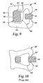
- the force needed to ligate the archwire to the appliance and the force needed to release the archwire from the appliance were determined for an appliance having a clip constructed as shown in Fig. 8 and for a prior art appliance having a clip constructed as shown in Fig. 10 .
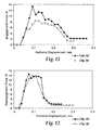
- a graph depicting the results determined for archwire ligation is set out in Fig. 11
- a graph depicting the results determined for archwire release is set out in Fig. 12 .
- the graph of Fig. 11 shows that a significantly higher force is needed for archwire ligation using the clip 36' depicted in Fig. 10 in comparison to the force needed for archwire ligation using the clip 36 depicted in Fig. 8 .
- the maximum force needed to push the archwire 40 in a lingual direction to ligate the archwire to the appliance 10' shown in Fig. 10 i.e., the maximum force needed to push the archwire 40 in a lingual direction in order to spread apart arm portions 48', 50' and move the archwire 40 into region 56'
- the maximum force needed to push the archwire 40 in a lingual direction to ligate the archwire 40 to the appliance 10 having the clip 36 was 8.3 Newtons.
- the graph set out in Fig. 12 shows that the force needed to disengage or release the archwire from the archwire slot of both appliances is approximately the same. This is an advantage in that the likelihood of unintentional release of the archwire from both appliances during the course of treatment is also approximately the same.
- a maximum force of 14.5 Newtons exerted on the archwire 40 in a buccolabial direction was needed to spread apart the arm portions 48', 50' and move the archwire 40 out of the region 56' in order to release the archwire 40 from the appliance.
- the maximum force exerted on the archwire 40 in a buccolabial direction that was needed to release the archwire 40 from the appliance 10 was 13.8 Newtons.
- both clips were made of the same material (super-elastic nitinol) and the thickness of the clips was 0.0128 inch (0.33 mm).
- the overall occlusal-gingival height and buccolabial-lingual width of the clip of the present invention were approximately 0.076 inch (1.88 mm) and 0.084 inch (2.13 mm) respectively.
- the occlusal-gingival height and buccolabial-lingual width for the clip 36' shown in Fig. 10 were approximately 0.064 inch (1.62 mm) and 0.079 inch (2.00 mm) respectively.
- the present invention facilitates insertion of the archwire 40 into the archwire slot 26 without adversely affecting the self-releasing aspects of the latch to any significant extent.
- This feature is a particular advantage in that the practitioner may ligate the archwire 40 to the appliance 10 with less force than might be otherwise possible.
- This feature is also beneficial to the patient, since less force is exerted on the patient's teeth during ligation and as a consequence any pain experienced by the patient is correspondingly reduced.
- the body and/or base may be made of a metallic (such as stainless steel) or plastic material (such as fiber-reinforced polycarbonate) instead of the ceramic materials mentioned above.
- the archwire slot liner 24 is optional and may be omitted if desired.
Abstract
Description
- This invention broadly relates to appliances that are used in the course of orthodontic treatment. More particularly, the present invention relates to a self-ligating orthodontic appliance such as a bracket or molar appliance having a latch that releasably retains an archwire in an archwire slot of the appliance.
- Orthodontic therapy is a specialized type of treatment within the field of dentistry, and involves movement of malpositioned teeth to orthodontically correct locations. Orthodontic treatment typically enhances the aesthetic appearance of the teeth, particularly in instances when the patient's front teeth are malpositioned or crooked. Orthodontic treatment can also improve the patient's occlusion so that the teeth function better with each other during mastication.
- Many types of orthodontic treatment programs involve the use of a set of tiny appliances and wires that are commonly known collectively as "braces". During such treatment programs, small slotted appliances known as brackets are fixed to the patient's anterior, cuspid and bicuspid teeth, and an archwire is inserted into the slot of each bracket. The archwire forms a track to guide movement of the teeth to orthodontically correct locations. End sections of the archwires are typically captured in molar appliances that are fixed to the patient's molar teeth.
- Recently, there has been increased interest in orthodontic appliances that have a latch for retaining the archwire in the archwire slot. Appliances of this type are widely known as self-ligating appliances and often obviate the need to use ligatures (such as wire ties or elastomeric O-rings) for retaining the archwire in the archwire slots. Improved self-ligating orthodontic appliances having a self-releasing latch are described in applicant's
U.S. Patent Nos. 6,302,688 and6,582,226 . - A recently introduced self-ligating appliance known as "SMARTCLIP" brand appliance from 3M Unitek Corporation has a latch that comprises two resilient clips, and each clip has a generally "C"-shaped configuration. The clips spread open to admit an archwire into an archwire slot of the appliance. Each clip is connected to a body of the appliance by a post that extends through the clip, and an outwardly extending base of the appliance helps to retain the clip in place on the post.
- Each of the documents
US 2004/0082826 andUS 2004/0082825 discloses an orthodontic appliance according to the preamble of claim 1. - The present invention is directed toward a self ligating orthodontic appliance having a latch that includes at least one clip. Each clip is connected to remaining components of the appliance by a post that extends through a recess of the clip. Each clip also has at least one protrusion that extends along a side of the post for retaining the clip in place.
- In more detail, the present invention is directed in one aspect to an orthodontic appliance that comprises a base, a body extending outwardly from the base and an archwire slot extending across the appliance in a generally mesial-distal direction. The appliance also includes a post extending outwardly from the body, and a latch for releasably retaining an archwire in the archwire slot. The latch comprises a clip with a region next to the archwire slot for receiving the archwire. The clip also includes a recess that receives the post, and the recess is in communication with the archwire- receiving region. The post includes a side that faces the region. The clip also includes at least one protrusion that extends along the side of the post between the region and the recess.
- Another aspect of the present invention is also directed toward an orthodontic appliance that comprises a base, a body extending outwardly from the base and an archwire slot extending across the appliance in a generally mesial-distal direction. The appliance further comprises a post extending outwardly from the body and a latch for releasably retaining an archwire in the archwire slot. The latch comprises a clip with a region next to the archwire slot for receiving an archwire. The clip also includes a recess that receives the post, and the recess is in communication with the archwire-receiving region. The post includes a side that faces the region. The clip also includes two protrusions that extend in opposite directions toward each other along the side of the post.
- Advantageously, it has been found that the clip of the present invention enables the archwire to be inserted into the archwire-receiving region with less force than might be otherwise expected. Consequently, the practitioner is able to ligate the archwire to the appliance with less force and as a result the procedure is less painful to the patient. This feature is particularly important for patients with teeth that are somewhat mobile due to previous orthodontic therapy since those teeth are known to be more sensitive to pain caused by the pressure of external forces.
- Further details of the invention are defined in the features of the claims.
-
-
Fig. 1 is a perspective view of an orthodontic appliance constructed in accordance with one embodiment of the present invention, looking at the appliance toward its mesial, buccolabial and gingival sides; -
Fig. 2 is an exploded perspective view of the appliance depicted inFig. 1 , looking at the appliance toward its mesial, buccolabial and occlusal sides; -
Fig. 3 is an assembled, front elevational view of the appliance shown inFigs. 1 and 2 , looking at the appliance toward its buccolabial side, and wherein one clip of the appliance has been omitted for purposes of illustration; -
Fig. 4 is a bottom view of the appliance illustrated inFig. 3 , looking at the appliance toward its gingival side; -
Fig. 5 is a side elevational view of the appliance shown inFigs. 1-4 , looking at the appliance toward its mesial side and illustrating the clip in place; -
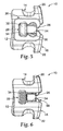
Fig. 6 is a side cross-sectional view taken along lines 6-6 ofFig. 3 , showing among other things the configuration of a neck of a post of the appliance; -
Fig. 7 is a view of the neck and clip alone, along with an exemplary archwire that is about to be received in an archwire slot of the appliance; and -
Fig. 8 is a view somewhat similar toFig. 7 except that the clip is shown in an open position as it might appear during insertion of the archwire into the archwire slot; -
Fig. 9 is a view somewhat similar toFig. 8 except that the clip is shown in an open position as it might appear during release of the archwire from the archwire slot; -
Fig. 10 is a view somewhat similar toFig. 8 except that a clip of prior art construction is illustrated for purposes of comparison; -
Fig. 11 is a graph depicting the force needed to insert an archwire into an archwire slot of an appliance having the clip shown inFig. 8 , along with the force needed to insert an archwire into an archwire slot of an appliance having the clip shown inFig. 10 ; and -
Fig. 12 is a graph somewhat similar toFig. 11 except that the forces needed to release an archwire from the archwire slot of the appliances are shown. - "Mesial" means in a direction toward the center of the patient's curved dental arch.
- "Distal" means in a direction away from the center of the patient's curved dental arch.
- "Occlusal" means in a direction toward the outer tips of the patient's teeth.
- "Gingival" means in a direction toward the patient's gums or gingiva.
- "Buccolabial" means in a direction toward the patient's lips or cheeks.
- "Lingual" means in a direction toward the patient's tongue.
- An orthodontic appliance constructed in accordance with one embodiment of the present invention is illustrated in
Figs. 1-8 and is broadly designated by thenumeral 10. Theappliance 10 in this instance is an orthodontic bracket that is adapted to be secured to an enamel surface of a patient's tooth, such as a buccolabial tooth surface. Alternatively, the appliance could be a molar appliance, an appliance for attachment to a lingual tooth surface, or any other appliance that is adapted to receive an archwire for controlling movement of the associated tooth during the course of orthodontic therapy. - The
appliance 10 includes abase 12 for bonding theappliance 10 directly to the patient's tooth enamel by the use of an adhesive. Preferably, thebase 12 has an outwardly facing concave compound contour that matches the convex compound contour of the patient's tooth surface to which it is bonded. Optionally, thebase 12 is provided with grooves, particles, recesses, undercuts, a chemical bond enhancement material or any other material or structure, or any combination of the foregoing that facilitates bonding of theappliance 10 directly to the patient's tooth surface. - A
body 14 extends outwardly from the base 12 in a generally buccolabial direction. Thebody 14 includes amesial body portion 16 and adistal body portion 18 that is spaced from themesial body portion 16. In this embodiment, each of theportions occlusal tiewing 20 and agingival tiewing 22, although one or more of thetiewings - Preferably, and as shown in
Figs. 1-3 , the body 14 (including thebody portions 16, 18) is integrally connected to thebase 12, and thebody 14 and the base 12 form a single, unitary component. However, other constructions are also possible. For example, if the base and the body are made of a metallic material, the base could be manufactured separately from the body and later welded or brazed to the body during an assembly operation. - The
appliance 10 also includes anarchwire slot liner 24 that is fixed to thebody portions archwire slot liner 24 defines occlusal, gingival and lingual sides of anarchwire slot 26. Thearchwire slot 26 longitudinally extends in a generally mesial-distal direction across theappliance 10, including through a channel of thebody portions archwire slot liner 24 is optional and may be omitted. If thearchwire slot liner 24 is omitted, the channel of thebody portions - The
base 12, thebody 14 and thearchwire slot liner 24 are preferably similar to the corresponding components of the appliances described inU.S. Patent Nos. 5,439,379 and5,366,372 . Preferably, thebase 12 and thebody 14 are made of a transparent monocrystalline ceramic material or a translucent polycrystalline ceramic material such as alumina, and thearchwire slot liner 24 is made of a metallic material. Examples of suitable materials and methods for constructing thearchwire slot liner 24, as well as suitable methods of attaching thearchwire slot liner 24 to thebody portions U.S. Patent Nos. 5,358,402 and5,380,196 . - Each of the
tiewings tiewings tiewings U.S. Patent Application Serial No. 10/770779, filed February 3, 2004 - The
appliance 10 includes amesial post 28 and adistal post 30 that are integrally connected to themesial body portion 16 and thedistal body portion 18 respectively. Theposts body 14. Preferably, eachpost archwire slot 26. As shown for example inFigs. 4-6 , theposts archwire slot 26. - The
mesial post 28 includes anoutermost head 32 and aneck 34 that integrally interconnects thehead 32 and themesial body portion 16. As depicted inFig. 6 , theneck 34 has a generally rectangular cross-sectional configuration when considered in reference planes perpendicular to the reference axis along which thepost 28 extends or when considered in reference planes generally perpendicular to a mesial-distal axis. Preferably, the occlusal, gingival and lingual sides of theneck 34 in regions along the innermost or distal end of theneck 34 include curved or chamfered sections that are connected to the mesial side of themesial body portion 16, for enhancing the strength of the connection between themesial post 28 and thebody 14. - As shown for example in
Fig. 5 , thehead 32 of thepost 28 has a generally trapezoidal configuration when viewed in a distal direction, or when viewed in reference planes that are perpendicular to the reference axis along which thepost 28 extends.Fig. 5 also illustrates in dashed lines the cross-sectional shape of theneck 34 for purposes of comparison. As illustrated, the height of theneck 34 and the height of thehead 32 are essentially the same along the lingual side of thepost 28 when considered in directions along an occlusal-gingival reference axis (i.e. along a vertical axis when viewingFigs. 5-8 ). However, along the buccolabial side of thepost 28, the height of thehead 32 is greater than the height of theneck 34 when considered in directions along an occlusal-gingival reference axis. - The
head 32 extends outwardly past the neck 34 a certain distance when considered in reference planes perpendicular to a mesial-distal reference axis or when considered in reference planes perpendicular to the reference axis along which thepost 28 extends. In the illustrated embodiment, thehead 32 extends outwardly past theneck 34 in at least one, and preferably in both directions along an occlusal-gingival reference axis, or in directions along a vertical axis when viewingFigs 5-8 . In the illustrated embodiment, this certain distance is determined by adding the distance that thehead 32 extends past theneck 34 in an occlusal direction to the distance that thehead 32 extends past theneck 34 in a gingival direction. This certain distance decreases as the lingual side of thepost 28 is approached and as athird section 46 of the clip 36 (as described below) is approached. This relationship is shown by the dashed lines inFig. 5 illustrating the occlusal and gingival sides of theneck 34, in comparison to the full lines that depict the occlusal and gingival sides of thehead 32. Preferably, this certain distance is zero or approximately zero in regions adjacent thethird section 46. - In this embodiment, the
archwire slot liner 24 has a rectangular mesial extension that extends over the buccolabial side of thepost 28 and is connected to the same by the methods described inU.S. Patent Nos. 5,358,402 and5,380,196 . However, other constructions are also possible. For example, thearchwire slot liner 24 may have a mesial extension that is somewhat "T"-shaped, to match the generally "T"-shaped configuration presented by theneck 34 and thehead 32 as depicted inFig. 3 . As yet another option, the mesial extension of thearchwire slot liner 24 may be omitted such that the mesial end of thearchwire slot liner 28 is flush with the mesial side of themesial body portion 16. - The
appliance 10 also includes a latch for releasably retaining an archwire in thearchwire slot 26. In the illustrated embodiment, the latch includes amesial clip 36 that is connected to themesial post 28, and adistal clip 38 that is connected to thedistal post 30. Themesial clip 36 is omitted fromFigs. 3, 4 and6 for purposes of illustration. - The
mesial clip 36, theneck 34 and anexemplary archwire 40 are shown alone inFigs. 7 and 8 . Themesial clip 36 includes an elongated occlusal orfirst section 42, an elongated second orgingival section 44 and an elongated lingual orthird section 46. The first andsecond sections clip 36 is relaxed, and thethird section 46 extends in a generally occlusal-gingival direction perpendicular to the direction of extension of thesections - The
third section 46 also integrally connects the first andsecond sections sections portions arm portion - The
sections neck 34 respectively. In addition, each of thesections neck 34. A rear (lingual) portion of the first andsecond sections third section 46 and theprotrusions 52 together at least partially define a recess 54 (seeFigs. 2 and8 ) for receiving theneck 34 of thepost 28. - A front (buccolabial) portion of the first and
second sections arm portions neck 34, together at least partially define aregion 56 for receiving thearchwire 40. As shown for example inFig. 5 , theregion 56 is aligned with thearchwire slot 26. Overall, theclip 36 presents a generally "C"-shaped configuration when looking in a mesial or distal direction. - The
clip 36 is shown in its normal, relaxed orientation inFigs. 1, 2 ,5 and7 . However, thearm portions archwire 40 into the archwire-receivingregion 56 when desired. To this end, the first andsecond sections clip 36 is opened and bend in respective arcs away from each other in order to enable thearm portions - The smooth, outer edge of the
arm portions clip 36 to open and admit thearchwire 40 into theregion 56 by pressing the archwire 40 against the outer curved edges of thearm portions archwire 40 on the curved edges, the first andsecond sections archwire 40 into theregion 56.Fig. 8 is an exemplary illustration showing theclip 36 opened, wherein thearm portions archwire 40 into theregion 56. - As the
clip 36 is opened, theprotrusions 52 slide across the buccolabial side of theneck 34. However, theprotrusions 52 extend inwardly and toward each other a distance sufficient to remain in contact with the buccolabial side of theneck 34 as theclip 36 is opened. As such, theclip 36 remains coupled to thepost 28 during such opening movements. - Once the
archwire 40 is received in theregion 56, the inherent resiliency of theclip 36, and particularly the resiliency of the first andsecond sections arm portions Figs. 1, 2 ,5 and7 in order to retain thearchwire 40 in thearchwire slot 26. Preferably, but not necessarily, theregion 56 is somewhat larger than the cross-section of thearchwire 40 in directions along both an occlusal-gingival reference axis as well as along a buccolabial-lingual reference axis, in order to avoid firm contact between theclip 36 and thearchwire 40. The spaces between theclip 36 and thearchwire 40 provide what is often referred to as "passive" ligation. - The clip 36 (including the first and
second sections 42, 44) is sufficiently stiff to retain thearchwire 40 in thearchwire slot 26 during the course of treatment so long as the forces exerted by thearchwire 40 on theappliance 10 are below a certain minimum value in a generally buccolabial direction (more particularly, in a direction opposite to the direction of insertion of thearchwire 40 into the archwire slot 26). However, whenever the forces exerted by thearchwire 40 on theappliance 10 in the same direction are greater than the minimum value, as might occur when unexpectedly high forces are encountered, the first andsecond sections arm portions clip 36 and release the archwire 40 from thearchwire slot 26. Further details regarding such forces are described in the aforementionedU.S. Patent Nos. 6,302,688 and6,582,226 . - Preferably, the
clip 36 is substantially identical to theclip 38 and thepost 28 is substantially identical in mirror image to thepost 30. The latch, comprising theclips archwire slot 26 in a generally buccolabial direction whenever thearchwire 40 exerts a force in the same direction on theappliance 10 that is in the range of about 0.2 lb (0.1 kg) to about 11 lb (5 kg), more preferably in the range of about 0.4 lb (0.2 kg) to about 5.5 lb (2.5 kg), and most preferably in the range of about 0.75 lb (0.34 kg) to about 3.0 lb (1.4 kg). Preferably, the minimum value is sufficiently high to prevent the archwire from unintentionally releasing from thearchwire slot 26 during the normal course of orthodontic treatment. As such, thearchwire 40 can exert forces on theappliance 10 sufficient to carry out the treatment program and move the associated teeth as desired. - Preferably, the minimum value for self-release (i.e., self-opening) of the latch is substantially less than the force required in the same direction to debond the
appliance 10 from the associated tooth. The minimum value for self-release of the latch is preferably less than about one-half of the force required in the same direction to debond theappliance 10 from the associated tooth. For example, if the expected bond strength of the adhesive bond between theappliance 10 and the associated tooth is 16 lbs (7.2 kg) in a buccolabial direction, the latch is constructed to self-release thearchwire 40 whenever thearchwire 40 exerts a force in the same buccolabial direction on theappliance 10 that is somewhat greater than about 8 lbs (3.6 kg). - To determine the force to release the latch, a section of archwire is selected having an area in longitudinally transverse sections that is complemental to (i.e., substantially fills) the cross-sectional area of the
archwire slot 32. Next, a sling is constructed and is connected to the archwire section at locations closely adjacent, but not in contact with the heads of theposts head 32. Optionally, the sling is welded or brazed to the archwire section. Next, the sling is pulled away from theappliance 10 while theappliance 10 is held in a stationary position, taking care to ensure that the longitudinal axis of the archwire section does not tip relative to the longitudinal axis of thearchwire slot 26. The force to release the latch may be determined by use of an Instron testing apparatus connected to the sling, using a crosshead speed of 0.5 in/min (1.3 cm/min). Alternatively, a shaker apparatus (such as Model 300 from APS Dynamics of Carlsbad, California) may be used along with a force transducer (such as model 208C01 from PCB of Buffalo, New York) to measure the force. - Preferably, the distance between the opposed ends of the
arm portions smallest archwire 40 expected to be used during the course of treatment. Thearchwire 40 need not fill thearchwire slot 26 and flatly engage the wall portions defining thearchwire slot 26 in all instances. For example, a somewhat smaller wire, and perhaps anarchwire 40 having a circular cross-sectional shape, may be used during a portion of the treatment program. The distance between the opposed ends of thearm portions appliance 10. - Preferably, and as mentioned above, the
distal clip 38 is substantially identical to themesial clip 36. Optionally, however, it is possible to construct theclips mesial clip 36 so that a somewhat greater force is needed to release the archwire 40 from thearchwire slot 26 in comparison to the force needed to release the archwire 40 from thedistal clip 38. Other options are also possible. - Optionally, the spring clips 36, 38 are cut from a flat section of metallic stock material. Suitable metallic materials include shape memory alloys such as alloys of nitinol and beta-titanium. The
clips clips - As presently preferred, the
clips clips clips clips second sections 42, 44 (i.e. a generally buccolabial direction in the illustrated embodiment ). - Subsequent to the EDM, laser cutting or chemical etching process, the
clips - Other optional aspects of the
clips 2004/0086825, published May 18,2004 . - During manufacture of the
appliance 10, thearchwire slot liner 24 is affixed to thebody 14 and theclips posts clip 36 to thepost 28, theclip 36 is opened by moving thesections head 32 and enable theneck 34 to be received in therecess 54 by moving theclip 36 in a distal direction. Next, pressure on thesections clip 36 springs back to its normal, relaxed configuration such as shown inFigs. 1, 2 ,5 and7 , whereupon it is held in place by thehead 32. - The present invention provides a significant advantage, in that the
protrusions 52 serve to hold theclip 36 in place on thepost 28. In particular, theprotrusions 52 help prevent theclip 36 from moving in a lingual direction and disengaging thepost 28 as might occur, for example, when thearchwire 40 is pressed against thearm portions archwire slot 26. Such construction avoids the need for a base flange or other structure located on the lingual side of thethird section 46, which in turn enables the base or "footprint" of theappliance 10 to be somewhat smaller than might otherwise be expected. - Furthermore, the present invention surprisingly allows the
archwire 40 to be inserted into thearchwire slot 26 with less force than expected, while the force needed to self-release the latch remains approximately the same. In one experimental analysis done by computer, using software "ANSYS 8.0" from ANSYS, Inc. of Canonsburg, Pennsylvania, the force needed to ligate the archwire to the appliance and the force needed to release the archwire from the appliance were determined for an appliance having a clip constructed as shown inFig. 8 and for a prior art appliance having a clip constructed as shown inFig. 10 . A graph depicting the results determined for archwire ligation is set out inFig. 11 , and a graph depicting the results determined for archwire release is set out inFig. 12 . - The graph of
Fig. 11 shows that a significantly higher force is needed for archwire ligation using the clip 36' depicted inFig. 10 in comparison to the force needed for archwire ligation using theclip 36 depicted inFig. 8 . InFig. 11 , the maximum force needed to push thearchwire 40 in a lingual direction to ligate the archwire to the appliance 10' shown inFig. 10 (i.e., the maximum force needed to push thearchwire 40 in a lingual direction in order to spread apart arm portions 48', 50' and move thearchwire 40 into region 56') was 13.3 Newtons. By contrast, the maximum force needed to push thearchwire 40 in a lingual direction to ligate thearchwire 40 to theappliance 10 having theclip 36 was 8.3 Newtons. - The graph set out in
Fig. 12 shows that the force needed to disengage or release the archwire from the archwire slot of both appliances is approximately the same. This is an advantage in that the likelihood of unintentional release of the archwire from both appliances during the course of treatment is also approximately the same. InFig. 12 , a maximum force of 14.5 Newtons exerted on thearchwire 40 in a buccolabial direction was needed to spread apart the arm portions 48', 50' and move thearchwire 40 out of the region 56' in order to release the archwire 40 from the appliance. By contrast, the maximum force exerted on thearchwire 40 in a buccolabial direction that was needed to release the archwire 40 from theappliance 10 was 13.8 Newtons. - In this experiment, both clips were made of the same material (super-elastic nitinol) and the thickness of the clips was 0.0128 inch (0.33 mm). In this experiment, the overall occlusal-gingival height and buccolabial-lingual width of the clip of the present invention were approximately 0.076 inch (1.88 mm) and 0.084 inch (2.13 mm) respectively. The occlusal-gingival height and buccolabial-lingual width for the clip 36' shown in
Fig. 10 were approximately 0.064 inch (1.62 mm) and 0.079 inch (2.00 mm) respectively. - As a result, the present invention facilitates insertion of the
archwire 40 into thearchwire slot 26 without adversely affecting the self-releasing aspects of the latch to any significant extent. This feature is a particular advantage in that the practitioner may ligate thearchwire 40 to theappliance 10 with less force than might be otherwise possible. This feature is also beneficial to the patient, since less force is exerted on the patient's teeth during ligation and as a consequence any pain experienced by the patient is correspondingly reduced. - It was also found in the computer analysis described above that the strain exerted on the
clip 36 during archwire ligation and release is reduced in comparison to the clip 36' illustrated inFig. 10 . The reduction is strain results in a higher fatigue life and reduces the possibility of fracture of theclip 36 during opening of theclip 36. - A number of other constructions are also possible. For example, the body and/or base may be made of a metallic (such as stainless steel) or plastic material (such as fiber-reinforced polycarbonate) instead of the ceramic materials mentioned above. Furthermore, the
archwire slot liner 24 is optional and may be omitted if desired. - The embodiments described in detail above and shown in the drawings are intended to exemplify the invention, and should not be deemed to limit the scope of the claims that follow.
Claims (10)
- An orthodontic appliance comprising:a base(12);a body (14) extending outwardly from the base;an archwire slot (26) extending outwardly across the appliance in a generally mesial-distal direction;a post (28) extending outwardly from the body; anda latch for releasably retaining an archwire in the archwire slot, wherein the latch comprises a clip (36) with a region next to the archwire slot for receiving an archwire, wherein the clip also includes a recess (54) that receives the post, wherein the recess (54) is in communication with the archwire-receiving region of the clip (56), wherein the post (28) includes a side that faces the archwire-receiving region of the clip, and characrerised in that the clip also includes at least one protrusion (52) that slides along the side of the post facing the archwire-receiving region as the clip is opened.
- An orthodontic appliance according to claim 1 wherein the protrusion of the clip is in contact with the post as an archwire is inserted into the archwire slot.
- An orthodontic appliance according to claim 1 wherein the clip includes two protrusions that slide along the side of the post facing the archwire-receiving region as the clip is opened and wherein the protrusions extend inwardly in opposite directions toward each other.
- An orthodontic appliance according to claim 1 wherein the clip includes a first section, a second section and a third section interconnecting the first section and the second section, and wherein the first section and the second section are movable away from each other to admit the post into the recess and are also movable away from each other to receive the archwire in the region.
- An orthodontic appliance according to claim 4 wherein the protrusion of the clip is in contact with the post as an archwire is received in the archwire-receiving region of the clip.
- An orthodontic appliance according to claim 4 wherein the clip includes two protrusions that slide along the side of the port facing the archwire-receiving region as the clip is opened, wherein the protrusions extend in opposite directions toward each other, wherein the side of the post has a certain size when considered in directions parallel to the directions of extension of the protrusions, and wherein the distance between the protrusions is smaller than the certain size.
- An orthodontic appliance according to claim 6 wherein the certain size is determined in directions along an occlusal-gingival reference axis.
- An orthodontic appliance according to claim 1 wherein the post includes a head (32) and a neck (34) interconnecting the head and the body, and wherein the side of the post is located on the neck.
- An orthodontic appliance according to claim 8 wherein the side of the post faces a buccolabial direction.
- An orthodontic appliance according to claim 1 wherein the appliance comprises two clips (36, 38).
Applications Claiming Priority (2)
| Application Number | Priority Date | Filing Date | Title |
|---|---|---|---|
| US10/900,779 US20060024634A1 (en) | 2004-07-28 | 2004-07-28 | Self-ligating orthodontic appliance with clip |
| PCT/US2005/023596 WO2006023103A1 (en) | 2004-07-28 | 2005-07-01 | Self-ligating orthodontic appliance with clip |
Publications (2)
| Publication Number | Publication Date |
|---|---|
| EP1796574A1 EP1796574A1 (en) | 2007-06-20 |
| EP1796574B1 true EP1796574B1 (en) | 2011-01-12 |
Family
ID=34982535
Family Applications (1)
| Application Number | Title | Priority Date | Filing Date |
|---|---|---|---|
| EP05769274A Not-in-force EP1796574B1 (en) | 2004-07-28 | 2005-07-01 | Self-ligating orthodontic appliance with clip |
Country Status (6)
| Country | Link |
|---|---|
| US (2) | US20060024634A1 (en) |
| EP (1) | EP1796574B1 (en) |
| JP (1) | JP4847449B2 (en) |
| AT (1) | ATE494853T1 (en) |
| DE (1) | DE602005025898D1 (en) |
| WO (1) | WO2006023103A1 (en) |
Families Citing this family (25)
| Publication number | Priority date | Publication date | Assignee | Title |
|---|---|---|---|---|
| US7621743B2 (en) * | 2002-11-26 | 2009-11-24 | Orthodontic Research And Development, S.L. | Orthodontic bracket |
| US20060051721A1 (en) * | 2002-11-26 | 2006-03-09 | Luis Carriere Lluch | Improvements to orthodontic supports applicable to teeth |
| US7377777B2 (en) * | 2005-12-23 | 2008-05-27 | 3M Innovative Properties Company | Orthodontic appliance with archwire-engaging clip |
| US7585171B2 (en) * | 2006-05-04 | 2009-09-08 | World Class Technology Corporation | Orthodontic bracket with rotary ligating cover |
| US7780443B2 (en) * | 2006-05-04 | 2010-08-24 | World Class Technology Corporation | Self-ligating bracket with rotary cover |
| US20080070182A1 (en) * | 2006-09-20 | 2008-03-20 | 3M Innovative Properties Company | Orthodontic elements and other medical devices with a fluorinated polymer, and methods |
| US20080138757A1 (en) * | 2006-12-12 | 2008-06-12 | 3M Innovative Properties Company | Orthodontic brace with reduced profile |
| US7670140B2 (en) * | 2006-12-20 | 2010-03-02 | 3M Innovative Properties Company | Orthodontic hand instrument for detaching brackets from teeth |
| DE102007008356B3 (en) * | 2007-02-20 | 2008-07-31 | Jahn, Ingolf, Dr. | Cube-shaped bracket for maxilla orthopedic treatment, has flexible element arranged in recess, where treatment wire is flexibly clampable with flexible element and end of flexible element rests against upper edge of recess |
| JP5215381B2 (en) * | 2007-04-30 | 2013-06-19 | スリーエム イノベイティブ プロパティズ カンパニー | Ceramic orthodontic bracket with improved release characteristics |
| US7963767B2 (en) * | 2007-07-23 | 2011-06-21 | Ultradent Products, Inc. | Self-ligating orthodontic bracket with sliding ligation cover |
| JP5525526B2 (en) | 2008-07-30 | 2014-06-18 | スリーエム イノベイティブ プロパティズ カンパニー | Low profile self-ligating orthodontic appliance with clip |
| MX2010008061A (en) | 2008-08-13 | 2010-11-22 | Ormco Corp | Aesthetic orthodontic bracket and method of making same. |
| AU2009238317B2 (en) | 2008-11-14 | 2011-10-06 | Ormco Corporation | Surface treated polycrystalline ceramic orthodontic bracket and method of making same |
| WO2010114692A1 (en) * | 2009-04-03 | 2010-10-07 | Ultradent Products, Inc. | Orthodontic brackets with pointed tie wings for improved ligation |
| EP2419042A1 (en) * | 2009-04-14 | 2012-02-22 | 3M Innovative Properties Company | Orthodontic connector providing controlled engagement with an orthodontic wire |
| ES2938049T3 (en) | 2009-10-16 | 2023-04-04 | Scripps Research Inst | Induction of stem cells |
| EP2506794A1 (en) * | 2009-12-02 | 2012-10-10 | 3M Innovative Properties Company | Orthodontic appliance with low profile clip |
| KR102071869B1 (en) | 2010-12-08 | 2020-01-31 | 스트라이트 인더스트리즈 리미티드 | Orthodontic gripping device |
| CN102525670B (en) * | 2012-02-23 | 2014-08-13 | 北京圣玛特科技有限公司 | Self-ligating bracket with elastic buckle |
| CN103565533A (en) * | 2013-11-08 | 2014-02-12 | 李钟昊 | Completely self-ligating bracket |
| US10085824B2 (en) | 2015-10-30 | 2018-10-02 | Ortho Organizers, Inc. | Self ligating orthodontic bracket |
| ITUB20155409A1 (en) * | 2015-11-10 | 2017-05-10 | Luigi Cursio | ORTHODONTIC SYSTEM WITH ARCHED THREAD CONNECTED TO AN ELEMENT |
| CN107174359A (en) * | 2016-03-10 | 2017-09-19 | 常州宁新医疗科技有限公司 | A kind of abnormal correction system of the prefabricated arch wire deflection of accurate conduction and preparation method thereof |
| CN109806015A (en) * | 2017-11-21 | 2019-05-28 | 哈尔滨石油学院 | A kind of tooth convenient for adjusting, which entangles, controls device |
Family Cites Families (33)
| Publication number | Priority date | Publication date | Assignee | Title |
|---|---|---|---|---|
| US1991047A (en) * | 1933-01-17 | 1935-02-12 | Boyd Charles Edward | Orthodontia band bracket |
| US3327393A (en) * | 1964-06-16 | 1967-06-27 | Allen C Brader | Orthodontic arch wire edgewise brackets |
| US3724074A (en) * | 1971-02-22 | 1973-04-03 | M Wallshein | Brackets for supporting arch wires, and adapted to function in orthodontic procedures in systems for tilting, uprighting and turning teeth |
| CH619611A5 (en) * | 1977-01-17 | 1980-10-15 | Foerster Bernhard Fa | |
| US4103423A (en) * | 1977-03-04 | 1978-08-01 | Kessel Stanley P | Orthodontic bracket |
| DE2919640C2 (en) * | 1979-05-16 | 1982-08-19 | Bernhard Förster GmbH, 7530 Pforzheim | Clamping and holding devices for orthodontic purposes |
| US4527975A (en) * | 1984-03-19 | 1985-07-09 | Joseph Ghafari | Cosmetic orthodontic device |
| US4551094A (en) * | 1985-01-31 | 1985-11-05 | Kesling Peter C | Edgewise bracket wire retaining clip |
| US4712999A (en) * | 1986-09-10 | 1987-12-15 | Farel Rosenberg | Convertible, self-ligating, archwire positioning orthodontic bracket |
| US5474444A (en) * | 1988-09-26 | 1995-12-12 | Wildman; Alexander J. | Multiwire arch system |
| US5269681A (en) * | 1992-05-15 | 1993-12-14 | Degnan Edward V | Integrated ligature and orthodontic bracket |
| US5630715A (en) * | 1993-01-21 | 1997-05-20 | Voudouris; John C. | Orthodontic bracket with an engagement mechanism for retaining an archwire |
| US5380196A (en) * | 1993-05-13 | 1995-01-10 | Minnesota Mining And Manufacturing Company | Orthodontic bracket with archwire slot liner |
| US5358402A (en) * | 1993-05-13 | 1994-10-25 | Minnesota Mining & Manufacturing Company | Ceramic orthodontic bracket with archwire slot liner |
| US5366372A (en) * | 1993-11-29 | 1994-11-22 | Minnesota Mining And Manufacturing Company | Method and apparatus for debonding ceramic orthodontic brackets |
| US5439379A (en) * | 1993-11-29 | 1995-08-08 | Minnesota Mining And Manufacturing Company | Ceramic orthodontic bracket with debonding channel |
| US5474445A (en) * | 1994-03-07 | 1995-12-12 | John Voudouris | Self-engaging twin edge-wise orthodontic bracket with pivotal latch |
| US5913680A (en) | 1994-03-07 | 1999-06-22 | Voudouris; John C. | Orthodontic bracket |
| US5857850A (en) * | 1994-03-07 | 1999-01-12 | Voudouris; John C. | Orthodontic appliance |
| US5700145A (en) * | 1995-06-05 | 1997-12-23 | Wildman; Alexander J. | Lingual bracket with hinged camming closure and releasable lock |
| EP1704890B1 (en) * | 1995-09-21 | 2009-01-21 | Covidien AG | Tapered and reinforced catheter |
| US5685711A (en) * | 1995-12-06 | 1997-11-11 | Hanson; G. Herbert | Self-ligating orthodontic brackets |
| US5711666A (en) * | 1996-10-22 | 1998-01-27 | Hanson; G. Herbert | Self-ligating orthodontic brackets |
| US6325622B1 (en) * | 1999-06-11 | 2001-12-04 | 3M Innovative Properties Company | Orthodontic bracket and latch assembly |
| US6302688B1 (en) * | 1999-09-27 | 2001-10-16 | 3M Innovative Properties Company | Orthodontic appliance with self-releasing latch |
| US6582226B2 (en) * | 1999-09-27 | 2003-06-24 | 3M Innovative Properties Company | Orthodontic appliance with self-releasing latch |
| US6554612B2 (en) * | 2001-06-25 | 2003-04-29 | 3M Innovative Properties Company | Orthodontic bracket with recessed attachment and method for making the same |
| JP2003260066A (en) * | 2002-03-07 | 2003-09-16 | Yoneo Sugano | Orthodontic bracket |
| US7014460B2 (en) * | 2002-11-04 | 2006-03-21 | 3M Innovative Properties Company | Orthodontic appliance with fatigue-resistant archwire retaining latch |
| US6957957B2 (en) * | 2002-11-04 | 2005-10-25 | 3M Innovative Properties Company | Molar appliance for orthodontic therapy |
| US7140876B2 (en) * | 2003-10-31 | 2006-11-28 | 3M Innovative Properties Company | Orthodontic appliance with latch for retaining an archwire |
| US7192274B2 (en) * | 2003-12-08 | 2007-03-20 | 3M Innovative Properties Company | Ceramic orthodontic appliance with archwire slot liner |
| US7140875B2 (en) * | 2004-02-03 | 2006-11-28 | 3M Innovative Properties Company | Orthodontic bracket with reinforced tiewings |
-
2004
- 2004-07-28 US US10/900,779 patent/US20060024634A1/en not_active Abandoned
-
2005
- 2005-07-01 EP EP05769274A patent/EP1796574B1/en not_active Not-in-force
- 2005-07-01 JP JP2007523579A patent/JP4847449B2/en not_active Expired - Fee Related
- 2005-07-01 DE DE602005025898T patent/DE602005025898D1/en active Active
- 2005-07-01 AT AT05769274T patent/ATE494853T1/en not_active IP Right Cessation
- 2005-07-01 WO PCT/US2005/023596 patent/WO2006023103A1/en active Application Filing
- 2005-12-23 US US11/317,346 patent/US7217125B2/en active Active
Also Published As
| Publication number | Publication date |
|---|---|
| EP1796574A1 (en) | 2007-06-20 |
| DE602005025898D1 (en) | 2011-02-24 |
| JP2008508026A (en) | 2008-03-21 |
| US20060024634A1 (en) | 2006-02-02 |
| ATE494853T1 (en) | 2011-01-15 |
| JP4847449B2 (en) | 2011-12-28 |
| US20060147868A1 (en) | 2006-07-06 |
| WO2006023103A1 (en) | 2006-03-02 |
| US7217125B2 (en) | 2007-05-15 |
Similar Documents
| Publication | Publication Date | Title |
|---|---|---|
| EP1796574B1 (en) | Self-ligating orthodontic appliance with clip | |
| EP1778122B1 (en) | Self-ligating orthodontic appliance with post for connection to a latch | |
| EP1558167B1 (en) | Orthodontic appliance with fatigue-resistant archwire retaining latch | |
| EP1843716B1 (en) | Pre-torqued orthodontic appliance with archwire retaining latch | |
| EP1962714B1 (en) | Orthodontic appliance with archwire-engaging clip | |
| US20170128169A1 (en) | Low profile self-ligating orthodontic appliance with clip | |
| EP1605860B1 (en) | Orthodontic brace with self-releasing appliances | |
| EP1558168B1 (en) | Molar appliance for orthodontic therapy | |
| US7140876B2 (en) | Orthodontic appliance with latch for retaining an archwire |
Legal Events
| Date | Code | Title | Description |
|---|---|---|---|
| PUAI | Public reference made under article 153(3) epc to a published international application that has entered the european phase |
Free format text: ORIGINAL CODE: 0009012 |
|
| 17P | Request for examination filed |
Effective date: 20070213 |
|
| AK | Designated contracting states |
Kind code of ref document: A1 Designated state(s): AT BE BG CH CY CZ DE DK EE ES FI FR GB GR HU IE IS IT LI LT LU LV MC NL PL PT RO SE SI SK TR |
|
| 17Q | First examination report despatched |
Effective date: 20070921 |
|
| DAX | Request for extension of the european patent (deleted) | ||
| GRAP | Despatch of communication of intention to grant a patent |
Free format text: ORIGINAL CODE: EPIDOSNIGR1 |
|
| GRAS | Grant fee paid |
Free format text: ORIGINAL CODE: EPIDOSNIGR3 |
|
| GRAA | (expected) grant |
Free format text: ORIGINAL CODE: 0009210 |
|
| AK | Designated contracting states |
Kind code of ref document: B1 Designated state(s): AT BE BG CH CY CZ DE DK EE ES FI FR GB GR HU IE IS IT LI LT LU LV MC NL PL PT RO SE SI SK TR |
|
| REG | Reference to a national code |
Ref country code: GB Ref legal event code: FG4D |
|
| REG | Reference to a national code |
Ref country code: CH Ref legal event code: EP |
|
| REG | Reference to a national code |
Ref country code: IE Ref legal event code: FG4D |
|
| REF | Corresponds to: |
Ref document number: 602005025898 Country of ref document: DE Date of ref document: 20110224 Kind code of ref document: P |
|
| REG | Reference to a national code |
Ref country code: DE Ref legal event code: R096 Ref document number: 602005025898 Country of ref document: DE Effective date: 20110224 |
|
| REG | Reference to a national code |
Ref country code: NL Ref legal event code: VDEP Effective date: 20110112 |
|
| LTIE | Lt: invalidation of european patent or patent extension |
Effective date: 20110112 |
|
| PG25 | Lapsed in a contracting state [announced via postgrant information from national office to epo] |
Ref country code: LV Free format text: LAPSE BECAUSE OF FAILURE TO SUBMIT A TRANSLATION OF THE DESCRIPTION OR TO PAY THE FEE WITHIN THE PRESCRIBED TIME-LIMIT Effective date: 20110112 Ref country code: IS Free format text: LAPSE BECAUSE OF FAILURE TO SUBMIT A TRANSLATION OF THE DESCRIPTION OR TO PAY THE FEE WITHIN THE PRESCRIBED TIME-LIMIT Effective date: 20110512 Ref country code: PT Free format text: LAPSE BECAUSE OF FAILURE TO SUBMIT A TRANSLATION OF THE DESCRIPTION OR TO PAY THE FEE WITHIN THE PRESCRIBED TIME-LIMIT Effective date: 20110512 Ref country code: LT Free format text: LAPSE BECAUSE OF FAILURE TO SUBMIT A TRANSLATION OF THE DESCRIPTION OR TO PAY THE FEE WITHIN THE PRESCRIBED TIME-LIMIT Effective date: 20110112 Ref country code: GR Free format text: LAPSE BECAUSE OF FAILURE TO SUBMIT A TRANSLATION OF THE DESCRIPTION OR TO PAY THE FEE WITHIN THE PRESCRIBED TIME-LIMIT Effective date: 20110413 Ref country code: ES Free format text: LAPSE BECAUSE OF FAILURE TO SUBMIT A TRANSLATION OF THE DESCRIPTION OR TO PAY THE FEE WITHIN THE PRESCRIBED TIME-LIMIT Effective date: 20110423 Ref country code: SE Free format text: LAPSE BECAUSE OF FAILURE TO SUBMIT A TRANSLATION OF THE DESCRIPTION OR TO PAY THE FEE WITHIN THE PRESCRIBED TIME-LIMIT Effective date: 20110112 |
|
| PG25 | Lapsed in a contracting state [announced via postgrant information from national office to epo] |
Ref country code: FI Free format text: LAPSE BECAUSE OF FAILURE TO SUBMIT A TRANSLATION OF THE DESCRIPTION OR TO PAY THE FEE WITHIN THE PRESCRIBED TIME-LIMIT Effective date: 20110112 Ref country code: BE Free format text: LAPSE BECAUSE OF FAILURE TO SUBMIT A TRANSLATION OF THE DESCRIPTION OR TO PAY THE FEE WITHIN THE PRESCRIBED TIME-LIMIT Effective date: 20110112 Ref country code: NL Free format text: LAPSE BECAUSE OF FAILURE TO SUBMIT A TRANSLATION OF THE DESCRIPTION OR TO PAY THE FEE WITHIN THE PRESCRIBED TIME-LIMIT Effective date: 20110112 Ref country code: CY Free format text: LAPSE BECAUSE OF FAILURE TO SUBMIT A TRANSLATION OF THE DESCRIPTION OR TO PAY THE FEE WITHIN THE PRESCRIBED TIME-LIMIT Effective date: 20110112 Ref country code: BG Free format text: LAPSE BECAUSE OF FAILURE TO SUBMIT A TRANSLATION OF THE DESCRIPTION OR TO PAY THE FEE WITHIN THE PRESCRIBED TIME-LIMIT Effective date: 20110412 Ref country code: SI Free format text: LAPSE BECAUSE OF FAILURE TO SUBMIT A TRANSLATION OF THE DESCRIPTION OR TO PAY THE FEE WITHIN THE PRESCRIBED TIME-LIMIT Effective date: 20110112 Ref country code: AT Free format text: LAPSE BECAUSE OF FAILURE TO SUBMIT A TRANSLATION OF THE DESCRIPTION OR TO PAY THE FEE WITHIN THE PRESCRIBED TIME-LIMIT Effective date: 20110112 Ref country code: PL Free format text: LAPSE BECAUSE OF FAILURE TO SUBMIT A TRANSLATION OF THE DESCRIPTION OR TO PAY THE FEE WITHIN THE PRESCRIBED TIME-LIMIT Effective date: 20110112 |
|
| PG25 | Lapsed in a contracting state [announced via postgrant information from national office to epo] |
Ref country code: EE Free format text: LAPSE BECAUSE OF FAILURE TO SUBMIT A TRANSLATION OF THE DESCRIPTION OR TO PAY THE FEE WITHIN THE PRESCRIBED TIME-LIMIT Effective date: 20110112 Ref country code: DK Free format text: LAPSE BECAUSE OF FAILURE TO SUBMIT A TRANSLATION OF THE DESCRIPTION OR TO PAY THE FEE WITHIN THE PRESCRIBED TIME-LIMIT Effective date: 20110112 |
|
| PLBE | No opposition filed within time limit |
Free format text: ORIGINAL CODE: 0009261 |
|
| STAA | Information on the status of an ep patent application or granted ep patent |
Free format text: STATUS: NO OPPOSITION FILED WITHIN TIME LIMIT |
|
| PG25 | Lapsed in a contracting state [announced via postgrant information from national office to epo] |
Ref country code: RO Free format text: LAPSE BECAUSE OF FAILURE TO SUBMIT A TRANSLATION OF THE DESCRIPTION OR TO PAY THE FEE WITHIN THE PRESCRIBED TIME-LIMIT Effective date: 20110112 Ref country code: SK Free format text: LAPSE BECAUSE OF FAILURE TO SUBMIT A TRANSLATION OF THE DESCRIPTION OR TO PAY THE FEE WITHIN THE PRESCRIBED TIME-LIMIT Effective date: 20110112 Ref country code: CZ Free format text: LAPSE BECAUSE OF FAILURE TO SUBMIT A TRANSLATION OF THE DESCRIPTION OR TO PAY THE FEE WITHIN THE PRESCRIBED TIME-LIMIT Effective date: 20110112 |
|
| 26N | No opposition filed |
Effective date: 20111013 |
|
| REG | Reference to a national code |
Ref country code: DE Ref legal event code: R097 Ref document number: 602005025898 Country of ref document: DE Effective date: 20111013 |
|
| PG25 | Lapsed in a contracting state [announced via postgrant information from national office to epo] |
Ref country code: MC Free format text: LAPSE BECAUSE OF NON-PAYMENT OF DUE FEES Effective date: 20110731 |
|
| REG | Reference to a national code |
Ref country code: CH Ref legal event code: PL |
|
| REG | Reference to a national code |
Ref country code: IE Ref legal event code: MM4A |
|
| PG25 | Lapsed in a contracting state [announced via postgrant information from national office to epo] |
Ref country code: CH Free format text: LAPSE BECAUSE OF NON-PAYMENT OF DUE FEES Effective date: 20110731 Ref country code: LI Free format text: LAPSE BECAUSE OF NON-PAYMENT OF DUE FEES Effective date: 20110731 |
|
| PG25 | Lapsed in a contracting state [announced via postgrant information from national office to epo] |
Ref country code: IE Free format text: LAPSE BECAUSE OF NON-PAYMENT OF DUE FEES Effective date: 20110701 |
|
| PG25 | Lapsed in a contracting state [announced via postgrant information from national office to epo] |
Ref country code: LU Free format text: LAPSE BECAUSE OF NON-PAYMENT OF DUE FEES Effective date: 20110701 |
|
| PG25 | Lapsed in a contracting state [announced via postgrant information from national office to epo] |
Ref country code: TR Free format text: LAPSE BECAUSE OF FAILURE TO SUBMIT A TRANSLATION OF THE DESCRIPTION OR TO PAY THE FEE WITHIN THE PRESCRIBED TIME-LIMIT Effective date: 20110112 |
|
| PG25 | Lapsed in a contracting state [announced via postgrant information from national office to epo] |
Ref country code: HU Free format text: LAPSE BECAUSE OF FAILURE TO SUBMIT A TRANSLATION OF THE DESCRIPTION OR TO PAY THE FEE WITHIN THE PRESCRIBED TIME-LIMIT Effective date: 20110112 |
|
| REG | Reference to a national code |
Ref country code: FR Ref legal event code: PLFP Year of fee payment: 11 |
|
| PGFP | Annual fee paid to national office [announced via postgrant information from national office to epo] |
Ref country code: IT Payment date: 20150727 Year of fee payment: 11 |
|
| REG | Reference to a national code |
Ref country code: FR Ref legal event code: PLFP Year of fee payment: 12 |
|
| REG | Reference to a national code |
Ref country code: FR Ref legal event code: PLFP Year of fee payment: 13 |
|
| PG25 | Lapsed in a contracting state [announced via postgrant information from national office to epo] |
Ref country code: IT Free format text: LAPSE BECAUSE OF NON-PAYMENT OF DUE FEES Effective date: 20160701 |
|
| REG | Reference to a national code |
Ref country code: FR Ref legal event code: PLFP Year of fee payment: 14 |
|
| PGFP | Annual fee paid to national office [announced via postgrant information from national office to epo] |
Ref country code: FR Payment date: 20190619 Year of fee payment: 15 |
|
| PGFP | Annual fee paid to national office [announced via postgrant information from national office to epo] |
Ref country code: GB Payment date: 20190626 Year of fee payment: 15 Ref country code: DE Payment date: 20190618 Year of fee payment: 15 |
|
| REG | Reference to a national code |
Ref country code: DE Ref legal event code: R119 Ref document number: 602005025898 Country of ref document: DE |
|
| GBPC | Gb: european patent ceased through non-payment of renewal fee |
Effective date: 20200701 |
|
| PG25 | Lapsed in a contracting state [announced via postgrant information from national office to epo] |
Ref country code: GB Free format text: LAPSE BECAUSE OF NON-PAYMENT OF DUE FEES Effective date: 20200701 Ref country code: FR Free format text: LAPSE BECAUSE OF NON-PAYMENT OF DUE FEES Effective date: 20200731 |
|
| PG25 | Lapsed in a contracting state [announced via postgrant information from national office to epo] |
Ref country code: DE Free format text: LAPSE BECAUSE OF NON-PAYMENT OF DUE FEES Effective date: 20210202 |