EP1796192B1 - Solid oxide fuel cell module, fuel cell system using the same and manufacturing method thereof - Google Patents
Solid oxide fuel cell module, fuel cell system using the same and manufacturing method thereof Download PDFInfo
- Publication number
- EP1796192B1 EP1796192B1 EP06256214A EP06256214A EP1796192B1 EP 1796192 B1 EP1796192 B1 EP 1796192B1 EP 06256214 A EP06256214 A EP 06256214A EP 06256214 A EP06256214 A EP 06256214A EP 1796192 B1 EP1796192 B1 EP 1796192B1
- Authority
- EP
- European Patent Office
- Prior art keywords
- fuel cell
- support
- pillars
- solid oxide
- cell module
- Prior art date
- Legal status (The legal status is an assumption and is not a legal conclusion. Google has not performed a legal analysis and makes no representation as to the accuracy of the status listed.)
- Ceased
Links
Images





Classifications
-
- H—ELECTRICITY
- H01—ELECTRIC ELEMENTS
- H01M—PROCESSES OR MEANS, e.g. BATTERIES, FOR THE DIRECT CONVERSION OF CHEMICAL ENERGY INTO ELECTRICAL ENERGY
- H01M8/00—Fuel cells; Manufacture thereof
- H01M8/02—Details
- H01M8/0202—Collectors; Separators, e.g. bipolar separators; Interconnectors
- H01M8/0247—Collectors; Separators, e.g. bipolar separators; Interconnectors characterised by the form
-
- H—ELECTRICITY
- H01—ELECTRIC ELEMENTS
- H01M—PROCESSES OR MEANS, e.g. BATTERIES, FOR THE DIRECT CONVERSION OF CHEMICAL ENERGY INTO ELECTRICAL ENERGY
- H01M8/00—Fuel cells; Manufacture thereof
- H01M8/10—Fuel cells with solid electrolytes
-
- H—ELECTRICITY
- H01—ELECTRIC ELEMENTS
- H01M—PROCESSES OR MEANS, e.g. BATTERIES, FOR THE DIRECT CONVERSION OF CHEMICAL ENERGY INTO ELECTRICAL ENERGY
- H01M4/00—Electrodes
- H01M4/86—Inert electrodes with catalytic activity, e.g. for fuel cells
- H01M4/8605—Porous electrodes
- H01M4/8621—Porous electrodes containing only metallic or ceramic material, e.g. made by sintering or sputtering
-
- H—ELECTRICITY
- H01—ELECTRIC ELEMENTS
- H01M—PROCESSES OR MEANS, e.g. BATTERIES, FOR THE DIRECT CONVERSION OF CHEMICAL ENERGY INTO ELECTRICAL ENERGY
- H01M4/00—Electrodes
- H01M4/86—Inert electrodes with catalytic activity, e.g. for fuel cells
- H01M4/8605—Porous electrodes
- H01M4/8626—Porous electrodes characterised by the form
-
- H—ELECTRICITY
- H01—ELECTRIC ELEMENTS
- H01M—PROCESSES OR MEANS, e.g. BATTERIES, FOR THE DIRECT CONVERSION OF CHEMICAL ENERGY INTO ELECTRICAL ENERGY
- H01M4/00—Electrodes
- H01M4/86—Inert electrodes with catalytic activity, e.g. for fuel cells
- H01M4/88—Processes of manufacture
- H01M4/8878—Treatment steps after deposition of the catalytic active composition or after shaping of the electrode being free-standing body
- H01M4/8882—Heat treatment, e.g. drying, baking
- H01M4/8885—Sintering or firing
-
- H—ELECTRICITY
- H01—ELECTRIC ELEMENTS
- H01M—PROCESSES OR MEANS, e.g. BATTERIES, FOR THE DIRECT CONVERSION OF CHEMICAL ENERGY INTO ELECTRICAL ENERGY
- H01M8/00—Fuel cells; Manufacture thereof
- H01M8/02—Details
-
- H—ELECTRICITY
- H01—ELECTRIC ELEMENTS
- H01M—PROCESSES OR MEANS, e.g. BATTERIES, FOR THE DIRECT CONVERSION OF CHEMICAL ENERGY INTO ELECTRICAL ENERGY
- H01M8/00—Fuel cells; Manufacture thereof
- H01M8/02—Details
- H01M8/0202—Collectors; Separators, e.g. bipolar separators; Interconnectors
- H01M8/0258—Collectors; Separators, e.g. bipolar separators; Interconnectors characterised by the configuration of channels, e.g. by the flow field of the reactant or coolant
-
- H—ELECTRICITY
- H01—ELECTRIC ELEMENTS
- H01M—PROCESSES OR MEANS, e.g. BATTERIES, FOR THE DIRECT CONVERSION OF CHEMICAL ENERGY INTO ELECTRICAL ENERGY
- H01M8/00—Fuel cells; Manufacture thereof
- H01M8/02—Details
- H01M8/0202—Collectors; Separators, e.g. bipolar separators; Interconnectors
- H01M8/0258—Collectors; Separators, e.g. bipolar separators; Interconnectors characterised by the configuration of channels, e.g. by the flow field of the reactant or coolant
- H01M8/026—Collectors; Separators, e.g. bipolar separators; Interconnectors characterised by the configuration of channels, e.g. by the flow field of the reactant or coolant characterised by grooves, e.g. their pitch or depth
-
- H—ELECTRICITY
- H01—ELECTRIC ELEMENTS
- H01M—PROCESSES OR MEANS, e.g. BATTERIES, FOR THE DIRECT CONVERSION OF CHEMICAL ENERGY INTO ELECTRICAL ENERGY
- H01M8/00—Fuel cells; Manufacture thereof
- H01M8/02—Details
- H01M8/0271—Sealing or supporting means around electrodes, matrices or membranes
-
- H—ELECTRICITY
- H01—ELECTRIC ELEMENTS
- H01M—PROCESSES OR MEANS, e.g. BATTERIES, FOR THE DIRECT CONVERSION OF CHEMICAL ENERGY INTO ELECTRICAL ENERGY
- H01M8/00—Fuel cells; Manufacture thereof
- H01M8/10—Fuel cells with solid electrolytes
- H01M8/1004—Fuel cells with solid electrolytes characterised by membrane-electrode assemblies [MEA]
-
- H—ELECTRICITY
- H01—ELECTRIC ELEMENTS
- H01M—PROCESSES OR MEANS, e.g. BATTERIES, FOR THE DIRECT CONVERSION OF CHEMICAL ENERGY INTO ELECTRICAL ENERGY
- H01M8/00—Fuel cells; Manufacture thereof
- H01M8/24—Grouping of fuel cells, e.g. stacking of fuel cells
-
- H—ELECTRICITY
- H01—ELECTRIC ELEMENTS
- H01M—PROCESSES OR MEANS, e.g. BATTERIES, FOR THE DIRECT CONVERSION OF CHEMICAL ENERGY INTO ELECTRICAL ENERGY
- H01M8/00—Fuel cells; Manufacture thereof
- H01M8/24—Grouping of fuel cells, e.g. stacking of fuel cells
- H01M8/241—Grouping of fuel cells, e.g. stacking of fuel cells with solid or matrix-supported electrolytes
- H01M8/2425—High-temperature cells with solid electrolytes
- H01M8/2432—Grouping of unit cells of planar configuration
-
- H—ELECTRICITY
- H01—ELECTRIC ELEMENTS
- H01M—PROCESSES OR MEANS, e.g. BATTERIES, FOR THE DIRECT CONVERSION OF CHEMICAL ENERGY INTO ELECTRICAL ENERGY
- H01M8/00—Fuel cells; Manufacture thereof
- H01M8/24—Grouping of fuel cells, e.g. stacking of fuel cells
- H01M8/2457—Grouping of fuel cells, e.g. stacking of fuel cells with both reactants being gaseous or vaporised
-
- Y—GENERAL TAGGING OF NEW TECHNOLOGICAL DEVELOPMENTS; GENERAL TAGGING OF CROSS-SECTIONAL TECHNOLOGIES SPANNING OVER SEVERAL SECTIONS OF THE IPC; TECHNICAL SUBJECTS COVERED BY FORMER USPC CROSS-REFERENCE ART COLLECTIONS [XRACs] AND DIGESTS
- Y02—TECHNOLOGIES OR APPLICATIONS FOR MITIGATION OR ADAPTATION AGAINST CLIMATE CHANGE
- Y02E—REDUCTION OF GREENHOUSE GAS [GHG] EMISSIONS, RELATED TO ENERGY GENERATION, TRANSMISSION OR DISTRIBUTION
- Y02E60/00—Enabling technologies; Technologies with a potential or indirect contribution to GHG emissions mitigation
- Y02E60/30—Hydrogen technology
- Y02E60/50—Fuel cells
-
- Y—GENERAL TAGGING OF NEW TECHNOLOGICAL DEVELOPMENTS; GENERAL TAGGING OF CROSS-SECTIONAL TECHNOLOGIES SPANNING OVER SEVERAL SECTIONS OF THE IPC; TECHNICAL SUBJECTS COVERED BY FORMER USPC CROSS-REFERENCE ART COLLECTIONS [XRACs] AND DIGESTS
- Y02—TECHNOLOGIES OR APPLICATIONS FOR MITIGATION OR ADAPTATION AGAINST CLIMATE CHANGE
- Y02P—CLIMATE CHANGE MITIGATION TECHNOLOGIES IN THE PRODUCTION OR PROCESSING OF GOODS
- Y02P70/00—Climate change mitigation technologies in the production process for final industrial or consumer products
- Y02P70/50—Manufacturing or production processes characterised by the final manufactured product
Definitions
- the present invention relates to a solid oxide fuel cell and a manufacturing method thereof. More particularly, the present invention relates to a solid oxide fuel cell module which has a unit fuel cell module with an electrode and gas flow passages integral with each other and a plurality of the module stacked vertically and thus is easily manufacturable, economical, easily sealable and high in current density due to no need for a separate gas flow passage layer and a plurality of current collecting boards, a fuel cell system using the same and a manufacturing method thereof.
- a solid oxide fuel cell (hereinafter, "SOFC") is highlighted as a third-generation fuel cell using a high efficiency low pollution electricity-generation method.
- the solid oxide fuel cell adopts thermo-chemically stable zirconia as an electrolyte with fuel and air electrodes attached thereto.
- the solid oxide fuel cell uses fuel gas such as hydrogen, methane or methanol without reformation and employs air or oxygen as an oxidant.
- the SOFC utilizes zirconia as an electrolyte and yttria-stabilized zirconia (hereinafter, YSZ) to stabilize its crystalline structure of the electrolyte.
- This material exhibits an oxygen ion conductivity which is characteristically governed by temperature, and a desired conductivity for the fuel cell is attainable at a temperate of 900°C to 1000°C . Therefore, the SOFC is typically operable at a temperature of 900°C to 1000°C and thus adopts ceramics for an electrode material to withstand such a high temperature.
- the fuel cell module is entirely made of ceramics.
- an ion conductivity of the YSZ electrolyte is at most 0.1S/cm even at a temperature of 1000 °C.
- a poreless and high-density thin film (10 ⁇ m to 30 ⁇ m) electrolyte layer should be coated to minimize YSZ-induced internal resistance.
- a conventional planar SOFC utilizes an electrolyte plate as a support to coat front and back sides of the plate with air electrode and fuel electrode, respectively.
- fuel and air flow passages are formed in an interconnection connecting between the air and fuel electrodes.
- Such a planar fuel cell module should demonstrate sufficient mechanical strength to ensure that the YSZ to serves as the support between the air and fuel electrodes.
- 8-YSZ zirconia having yttria added at an amount of 8 mol%) is weak in mechanical strength.
- the support, ie. the electrolyte layer, of the planar SOFC needs to be thick. This increases voltage sag caused by internal resistance from inside the electrolyte, causing deterioration of the capability of the fuel cell module. Moreover, the planar SOFC should be sealed in all edge portions thereof to prevent gas mixing in upper and lower parts of the cell.
- glass was chiefly used as a sealing material.
- the glass material starts to soften from a temperature of 600°C and thermal expansion during the subsequent temperature rise imposes strains between the respective fuel cell modules. This increases the risk of gas leakage, potentially damaging the fuel cell modules. Therefore, the glass material for sealing needs to be improved to be commercially viable.
- Such a conventional round tubular cell is slightly inferior to the planar cell structure in terms of current density of a stack itself, but remarkably superior in terms of strength and gas sealing.
- This structure has an air electrode, a solid electrolyte, a fuel electrode and a current collecting layer stacked in order on a porous support tube made of zirconia oxide, thereby forming a unit fuel cell.
- a gas sealing material is not required to be disposed between electrodes, thereby freeing the fuel cell from a problem associated with ceramic sealing which arises in the planar cell.
- the fuel cell itself is of a robust ceramic structure with respective unit cells thereof formed on the secure support. Thus, the fuel cell is superbly resistant to thermal expansion.
- a metal interconnection can be employed owing to contact between the unit cells in a reducing atmosphere.
- one of the fuel cell modules alone fails to boost capacity.
- the fuel cell modules are connected with each other in series or parallel to form a stack.
- the round tubular cell having the fuel cell modules connected with each other, as just described has a current path that is elongated to allow current generated to flow along a thin electrode surface, thereby potentially raising internal resistance of the entire fuel cell.
- the fuel cell modules when stacked, result in unnecessary space utilisation inside and outside the round tubular cell, thereby restricting current density per volume.
- the fuel cell modules feature both the planar cell structure and the round tubular cell structure, thereby solving a sealing problem of the planar cell. Furthermore, a flat tube type structure and a stack thereof are being developed to enhance current density as taught in Korean Patent Publication Application No. 10-2005-0021027 , U.S Patent No US 6416897 , and US Patent No. 6429051 .
- the flat tube type structure when stacked, also necessitates an electrical interconnection material for electrical and gas flow passages to enable flow of gases to the air or fuel electrodes.
- This increases mechanical strength of the stack and enlarges a contact area between the fuel cell modules to boost current density.
- the metal interconnection characteristically may suffer thermal stress due to difference in thermal expansion with the ceramic fuel cell module when operating at a high temperature.
- the need for using an interconnection material that has a good stability for thermal and electrical properties even during long operation at a high temperature increases the price and also volume and weight of the stack.
- the present invention has been made to solve the foregoing problems of the prior art and it is therefore an aim according to certain embodiments of the present invention is to provide a solid oxide fuel cell module which is easily manufacturable, easily sealable, and high in current density and a manufacturing method thereof.
- Another aim according to certain embodiments of the invention is to provide a solid oxide fuel cell module which obviates a need for a separate gas flow passage layer or a current collecting layer for electrical connection and thus is simple-structured, easily manufacturable, convenient and mass-producible and a manufacturing method thereof.
- Another aim according to certain embodiments of the invention is to provide a solid oxide fuel cell module which is considerably reduced in manufacturing costs and noticeably increased in current density due to small internal resistance of an electrode and can be manufactured in large size and large capacity, and a manufacturing method thereof.
- a solid oxide fuel cell module for generating electricity using fuel gas and oxygen, comprising: a support made of a first catalytic material so as to be an electrode, having a plurality of flow passages formed inside the support forming a first fluid flow part, and a plurality of pillars integrally produced from an outer surface of the support so as to form flow passages forming a second fluid flow part; an electrolyte layer coated on the outer surface of the support excluding top surfaces of the pillars; a coating layer made of a second catalytic material so as to be the other electrode and coated on a outer surface of the electrolyte layer excluding the pillars; and a current collecting layer coated on the top surfaces of the pillars.
- a method for manufacturing a solid oxide fuel cell module comprising steps of: extruding a support made of a first catalytic material so as to be an electrode, having one or more flow passage formed inside the support forming first fluid flow part and elongated protrusions on a surface of the support; forming a plurality of pillars integrally by polishing and removing the elongated protrusions on a top surface of the support so as to form flow passages forming a second fluid flow part; coating an electrolyte layer on the outer surface of the support excluding top surfaces of the pillars; forming a coating layer of a second catalytic material on an outer surface of the electrolyte layer excluding the pillars so as to be the other electrode; and coating a current collecting layer on the top surfaces of the pillars.
- the support has a plurality of partition walls therein to form a plurality of the flow passages, and the plurality of pillars on a top surface thereof, the module further comprising a plurality of the supports stacked to form the flow passages between the pillars.
- the support has an elongated rectangular cross-section.
- the support is easily prepared by extrusion molding and sintering an anode or cathode-forming catalytic material in an extrusion machine.
- the support is provided with a thin coat thereon, the thin coat including the electrolyte layer, the coating layer being made of a catalytic material having an opposite polarity to the support and a metallic material of the current collecting layer.
- a plurality of fuel cell modules are stacked inside the casing, each of the fuel cell modules including a support made of a first catalytic material, a first fluid flow part formed inside the support, a second fluid flow part formed in an exterior of the support, and including an electrolyte layer, a coating layer of a second catalytic material and a current collecting layer formed on an outer surface of the support.
- the first fluid part and the second fluid part of the stacked fuel cell modules are disposed to cross each other to enable gas flow.
- the first fluid flow part having the flow passages formed between the partition walls inside serves as a gas flow passage for air or fuel electrode.
- the second fluid flow part having flow passages formed between the pillars on a top surface of the support serves as a gas flow passage for the opposite electrode when the fuel cell modules are stacked.
- FIG. 1 is a perspective view illustrating a support for manufacturing a solid oxide fuel cell module according to the invention:
- FIG. 2 is a perspective view illustrating a support having square pillars formed on a top surface thereof to manufacture a solid oxide fuel cell module;
- FIG. 3 is a perspective view illustrating a support having elongated pillars formed on a top surface thereof to manufacture a solid oxide fuel cell module according to the invention
- FIG. 4 is a perspective view illustrating a solid oxide fuel cell module according to the invention.
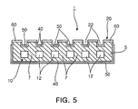
- FIG. 5 is a cross-sectional view illustrating a solid oxide fuel cell module according to the invention.
- FIG. 6 is a perspective view illustrating a stack of solid oxide fuel cell modules according to the invention.
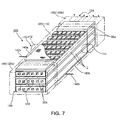
- FIG. 7 is a partially broken perspective view illustrating a solid oxide fuel cell according to the invention.
- FIG. 8 is an explanatory view illustrating operation principle of a solid oxide fuel cell according to the invention.
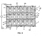
- FIG. 9 is a cross-sectional view illustrating a solid oxide fuel cell according to the invention.
- FIG. 10 is a cross-sectional view illustrating a solid oxide fuel cell according to the invention.
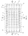
- FIG. 11 is a cross-sectional view illustrating a solid oxide fuel cell according to the invention.
- a solid oxide fuel cell module 1 of the invention includes a support 5 made of a first catalytic material. As shown in FIGs. 1 and 2 , the support 5 belongs to a structure of the fuel cell.
- the support 5 is extrusion molded with air (oxygen) electrode (cathode) or fuel electrode (anode)- forming catalytic material.
- the air (oxygen) electrode (cathode) adopts e.g., LSM (LaSrMnO 3 ) while the fuel electrode (anode) uses e.g., Ni/YSZ (cermet).
- LSM LaSrMnO 3
- Ni/YSZ cermet
- YSZ is yttria-stabilized zirconia.
- the catalytic material for the air and fuel electrodes is illustrative of but not limitative of the invention and may be varied.
- the support 5 has a plurality of partition walls 7 therein to form a plurality of flow passages 12, thereby forming a first fluid flow part 10.
- the support 5 made of the catalytic material of air electrode allows air to flow in the flow passages 12 of the first fluid flow part 10, while the support 5 made of the catalytic material of fuel electrode allows fuel gas to flow in the flow passages 12 of the first fluid flow part 10.
- the flow passages 12 of the support body 5 are honeycomb-shaped but can be modified in their shape as long as gas can flow uniformly therein.
- the gas flow passages 12 are of regular square or rectangular cross-sections.
- the gas flow passages 12 each have an inner width of 0.1 mm to 10 mm, more preferably, 1 mm to 3 mm and the partition walls 7 between the flow passage 12 each have a thickness of 0. 1 mm to 5mm, more preferably, 1 mm to 3mm.
- the flow passages 12 of the first fluid flow part 10 formed inside the support 5 have a regular square or rectangular cross-section as just described. But the invention is not limited thereto. That is, the flow passages 12 of the first fluid flow part 10 may be modified in their shape if the support 5 is long tube-shaped and has the gas flow passages 12 of the first fluid flow part 10 formed therein.
- the invention includes various configurations of the flow passages 12 of the first fluid flow part 10.
- the support 5 includes a second fluid flow part 20 having a plurality of pillars 24 protruded from an outer surface thereof and flow passages 22 formed between the pillars 24.
- a second fluid flow part 20 having a plurality of pillars 24 protruded from an outer surface thereof and flow passages 22 formed between the pillars 24.
- elongated protrusions 26 on the top surface of the support 5 can be polished and removed appropriately.
- the pillars 24 act as an electrical interconnection for electrically connecting an overlying fuel cell module 1 when a plurality of the supports 5 is stacked. Also, the pillars 24 constitute the flow passages 22 of the second fluid flow part 20 to ensure fuel is supplied to between the pillars 24.
- the support 5 has the pillars 24 intensively populated in a central portion of the top surface thereof, leaving pillarless areas 28 at opposite edges thereof.
- the pillars 24 each have a height of 0.1 mm to 10 mm and a width of 0.1 mm to 10mm, preferably 1 mm to 3mm, and 1 mm to 3mm, respectively.
- the pillars are spaced apart from each other at a distance of 0.1 mm to 10mm, preferably 1 mm to 5mm .
- the pillarless areas 28 at the opposite .edges of the top surface of the support 5 are located outside a heater of a fuel cell system 100 described later.
- the pillarless areas 28 at the opposite edges of the support 5 facilitate gas sealing and gas supply.
- additional sealing materials 30a and 30b may be disposed to seal the sides of gas flowing through the second fluid flow part 20.
- the pillars 24 of the support 5 When the unit fuel cell module 1 of the support 5 is formed and operated, the pillars 24 of the support 5 generate current electro-chemically by oxidation and reduction in a high temperature furnace, i.e., a heater.
- the pillars 24 protruded from the support 5 may be configured as a hexahedron having a square crosssection as shown in FIG. 2 .
- the pillars 24 may be altered in shape, size and height as long as the pillars 24 perform their function.
- FIG. 3 illustrates a modification of the pillars 24. That is, as shown in FIG. 2 , in place of the short pillars 24, a plurality of pillars 32 are elongated in parallel with each other on the top surface of the support 5.
- the elongated pillars 32 are provided at one side thereof an inflow hole 34 and at the opposite side thereof an exhaust hole 36.
- the inflow hole 34 and exhaust hole 36 constitute elongated flow passages 38 with the elongated pillars 32.
- the elongated flow passages 38 are formed such that a direction from the inflow hole 34 to the exhaust hole 36 is perpendicular to a flow direction of the flow passages 12 of the first fluid flow part 10.
- the elongated pillars 32 differ from the shorter pillars 24 described in FIG. 2 only in terms of shape but function identically. Now the shorter pillars 24 will be explained in greater detail. But the details described are applicable to the elongated pillars 32.
- the solid oxide fuel cell module of the invention includes an electrolyte layer 40 coated on an outer surface of the support 5 excluding top surfaces of the pillars 24.
- yttria-stabilized zirconia (YSZ) constituting the electrolyte layer 40 of the fuel cell system 100 is uniformly coated on the outer surface of the support 5, as shown in FIGs. 4 and 5 .
- the electrolyte layer 40 is thoroughly coated on the outer surface of the support 5 excluding the top surface of the pillars 24 which serves as an electrical path.
- a coating layer 50 made of a second catalytic material is formed on a top surface of the electrolyte layer 40 excluding the pillars 24.
- the coating layer 50 is made of a catalytic material having an opposite electrode polarity to the catalytic material of the support 5.
- the coating layer 50 is coated on an outer surface of the electrolyte layer 40 excluding the top surfaces and some side portions of the pillars 24.
- the coating layer 50 is made of a catalytic fuel electrode material.
- the coating layer 50 is made of a catalytic air electrode material.
- a current collecting layer 60 is coated on the top surfaces of the pillars 24.
- the current collecting layer 60 is thoroughly coated on the top surfaces of the pillars 24 as thinly as possible so that gas is not leaked.
- the current collecting layer 60 is an area for coating interconnections necessary for stacking a plurality of the fuel cell modules 1.
- the current collecting layer 60 is coated with metal particles and then thermally sintered.
- the current collecting layer 60 is coated via chemical vapor deposition (CVD) using metal compounds.
- CVD chemical vapor deposition
- the current collecting layer 60 is connected to the electrolyte layer 40 and is thoroughly coated to prevent gas from leaking between the electrolyte layer 40 and the current collecting layer 60.
- a material for the current collecting layer 60 is electrically conductive and thermally stabilizing for a long time at an operating temperature of the fuel cell system 100. Also, the material for the current collecting layer 60 is not gas permeable, thereby facilitating stacking of the plurality of fuel cell modules 1.
- the material for the current collecting layer 60 can be varied irrespective of composition thereof as long as the material assures the stacking as just described.
- the electrolyte layer 40, coating layer 50, and current collecting layer 60 each have a thickness up to 1000 ⁇ m, more preferably up to 200 ⁇ m.
- the electrolyte layer 40 and the current collecting layer 60 do not abut or overlap each other such that different types of two gases, i.e., air and fuel gas, do not mix together. Furthermore, the current collecting layer 50 and the coating layer 60, when coated, do not abut each other and therefore are electrically insulated.
- the fuel cell module 1 of the invention features a stack structure with a stack bundle to form the fuel cell.
- a plurality of the fuel cell modules 1 is arranged in parallel horizontally to form a larger-sized stack.
- Support bars 65 located between the stacked fuel cell modules 1 anchor the fuel cell modules 1 stacked vertically in a horizontal direction. Also, the support bars 65 space the stacked fuel cell modules 1 apart from each other horizontally, thereby serving as a spacer to electrically insulate the fuel cell modules 1.
- Such support bars 65 may be made of a material having no electrical conductivity and good mechanical strength at a high temperature.
- the support bars 65 may be variously configured and composed as long as they perform functions as just described.
- the solid oxide fuel cell system 100 having the fuel cell modules 1 stacked therein according to the invention generates electricity using fuel gas and air.
- the solid oxide fuel cell system 100 of the invention includes a hollow casing 105.
- the hollow casing 105 includes a first cover 110, surrounding a central portion of the stacked fuel cell modules where the pillars 24 are formed to shield the central portion from the outside, and second and third covers 120a and 120b surrounding end portions of the fuel cell modules 1 at both sides of the first cover to shield the end portions from the outside.
- the first cover 110 has both sides located at the sealing materials 30a and 30b of the fuel cell modules 1.
- the first cover 110 is provided at one side thereof with an entrance 112 to supply fuel gas or air to the second fluid flow part 20 and at an opposite side thereof with an exit 114.
- the second cover 120a and the third cover 120b are configured as a sealing structure for surrounding end portions of the fuel cell modules 1.
- one of the second and third covers 120a and 120b is provided with an entrance 122 to supply air or fuel gas to the first fluid flow part 10 of fuel cell module 1 and the other one of the second and third covers 120a and 120b is provided with an exit 124.
- Each of the fuel cell modules 1 stacked inside the casing includes a support 5 made of a first catalytic material, a first fluid flow part 10 formed inside the support 5, a second fluid flow part 20 formed in an exterior of the support 5, and includes an electrolyte layer 40, a coating layer 50 and a current collecting layer 60 formed on an outer surface of the support 5.
- the fuel cell modules 1 stacked inside the casing 105 include current collecting boards 140a and 140b disposed on top and underside surfaces of the casing to collect current from the fuel cell modules 1.
- An upper current collecting board 140a is electrically connected to the current collecting layer 60 of an uppermost one of the fuel cell modules 1.
- a lower current collecting board 140b is electrically connected to the coating layer 50 of a lowermost one of the fuel cell modules 1.
- the current collecting boards 140a and 140b extract direct current to outside through conducting lines 142a, 142b.
- the solid oxide fuel cell system 100 of the invention includes a first fluid supply part 150 having chambers connected to the fuel cell modules to supply a first fluid to the first fluid flow part 10 of the fuel cell modules 1.
- the first fluid supply part 150 includes the second and third covers 120a and 120b disposed at both sides of the stacked fuel cell modules 1.
- Such a first fluid supply part 150 is configured as a sealing structure such that the second and third covers 120a and 120b constituting a portion of the casing 105 surround end portions of the fuel cell modules 1 in which the chambers inside communicate with each other through the first fluid flow parts of the fuel cell modules 1.
- one of the second and third covers 120a and 120b is provided with an entrance 122 to supply air or fuel gas to the inside chambers and the other one of the second and third covers 120a and 120b is provided with an exit.
- the first fluid i.e., air or fuel gas flows from the entrance of the second cover 120a to the exit 124 of the third cover 120b through the first fluid flow parts 10 of the stacked fuel cell modules 1.
- the third cover 120b is provided with the entrance for the first fluid supply part 150, the first fluid, i.e., air or fuel gas flows from the third cover 120b toward the second cover 120a.
- the second fluid is fuel gas, and vice versa.
- the solid oxide fuel cell system 100 of the invention includes a second fluid supply part 170 having chambers connected to the fuel cell modules 1 for supplying the second fluid to the second fluid flow parts 20 of the fuel cell modules 1.
- the second fluid flow part 170 includes a first cover 110 which surrounds a central portion of the stacked fuel cell modules 1 where the pillars 24 are formed to shield the central portion from the outside.
- the first cover 110 of the second fluid flow part 170 constitutes a portion of the casing 105 and has both sides located at the sealing materials 30a and 30b of the fuel cell modules 1.
- the first cover 110 is provided at one side thereof with an entrance 112 to supply fuel gas or air to the second fluid flow part 20 of the stacked fuel cell modules and at an opposite side thereof with the exit 114.
- the second fluid supply part 170 as just described is configured as a sealing structure such that the first cover 110 surrounds the pillars 24 of the stacked fuel cell modules 1 in which chambers at the entrance 112 and exit 114 communicate with each other through the second fluid flow part 20 of the stacked fuel cell modules 1.
- the second fluid i.e., fuel gas or air flows toward the exit 114 through the second fluid flow part 20 of the stacked fuel cell modules 1.
- the first fluid is fuel gas, and vice versa.
- the chamber at the entrance 112 of the first fluid supply part 150 and the chambers at the entrance 112 of the second fluid supply part 170 serve as a distribution area for supplying and exhausting air or fuel gas uniformly through the first fluid flow part 10 and the second fluid flow part 20, respectively.
- the invention includes a heater 180 for heating the fuel cell modules 1 to a reaction temperature.
- the heater 180 has its heat source located on an outer periphery of the first cover 110 of the casing 105 and heats an internal space thereof to a reaction temperature of 1000°C through the first cover 110.
- a fuel cell module 1 of the invention should be manufactured.
- a support 5 made of a first catalytic material and having flow passages 12 of a first fluid flow part 10 therein is prepared.
- a plurality of partition walls 7 are formed inside an elongated rectangular flat tube to form a first fluid part 10 having the flow passages 12 shaped as a honeycomb. Then, as shown in FIG. 1 , protrusions 26 with uniform width and height are formed in parallel along a length direction on an outer surface of the support 5.
- This protuberant type of support 5 is easily manufacturable via extrusion-molding or sintering using a typical extruder.
- the protrusions 5 of the support 5 are machined to form a plurality of pillars 24 and flow passages 22 of a second fluid flow part 20 between the pillars 24.
- both side ends of the protrusions 26 are removed to a predetermined length along a length direction to form a flat portion or an area 28 where sealing materials 30a and 30b are located. Then the sealing materials 30a and 30b are attached to form a gas sealing part. Also, the protrusions 26 in a central portion of the support 5 are removed with a predetermined pattern to form the second fluid flow part 20 therebetween. A second fluid flowing through the second fluid flow part 20 is induced perpendicularly, i.e., at a right angle with respect to a first fluid flowing through the first fluid flow part 10. This fundamentally prevents the first and second fluids from being mixed together.
- an electrolyte layer 40 is coated on an outer surface of the support excluding top surfaces of the pillars 24.
- the electrolyte layer 40 is coated and sintered on the entire outer surface excluding the top surfaces of the pillars 24.
- a coating layer 50 of a second catalytic material is formed on a top surface of the electrolyte layer 40 excluding the pillars 24.
- the catalytic material of an opposite polarity to the support 5 is coated and sintered on an outer surface of the electrolyte layer 40 excluding the top surfaces and some side portions of sides of the pillars 24.
- a current collecting layer 60 is coated on the top surfaces of the pillars.
- a metal material is coated as thinly and thoroughly as possible on the top surfaces of the pillars 24, thereby completing a plurality of unit fuel cell modules 1.
- the unit fuel cell modules 1 manufactured feature a unit stack structure, in which constituents are only stacked vertically without further employing a plurality of current collecting metals or the gas flow passages 12. Also, such stacked structures can be disposed in parallel to configure a large-capacity fuel cell system 100.
- the fuel cell module 1 and the fuel cell system 100 have the first fluid supplied through the first fluid supply part 150 and the second fluid supplied through the second fluid supply part 170.
- the first fluid is supplied perpendicular to the second fluid.
- the first fluid induced through the first fluid supply part 150 is one of air and fuel gas.
- the support 5 forms an air electrode (cathode) and is made of a catalytic material for example having a formula of LSM (LaSrMnO 3 ).
- the support 5 forms a fuel electrode (anode) and is made of a catalytic material for example having a formula of Ni/YSZ (cermet).
- the second fluid fed through the second fluid supply part 170 is the other one of air and fuel gas. That is, in a case where the first fluid is air, the second fluid is fuel gas, and vice versa.
- the coating layer 50 is formed of a catalytic material of fuel electrode (anode), as exemplified by Ni/YSZ (cermet).
- the coating layer 50 is formed of a catalytic material of air electrode (cathode), as exemplified by LSM (LaSrMnO 3 ).
- the solid oxide fuel cell system 100 of the invention needs to be heated to about 1000°C through a heater 180 to generate electricity.
- the heater 180 is disposed in an outer periphery of the first cover 110 and heats inside the first cover 110.
- the first cover 110 acts as a furnace and experiences oxidation and reduction of the fuel cell system 100.
- the heater 180 may utilize an electrical resistance coil as a heat source.
- the heater may adopt a direct flame such as a burner as a heat source to heat the first cover 110 from outside.
- Such heating methods are illustrative of but not limitative of the invention.
- the first cover 10 undergoes chemical reactions therein as follows.
- Such chemical reaction allows current to flow in the current collecting layers 60 disposed in the respective fuel cell modules 1.
- electrons move along a vertical stack direction as if cells are connected in series.
- direct current can be extracted from the current collecting boards 140a and 140b disposed in upper and lower parts of the stacked fuel cell modules 1.
- the support 5 serves as air electrode and the coating layer 50 serves as fuel electrode so that the upper current collecting board 140a forms an anode and the lower current collecting board 140b forms a cathode.
- the oxygen ions. (O 2- ) released due to catalytic action of the support 5 move to the fuel electrode, and electrons 2e- released by coupling the fuel and the oxygen ion due to catalytic action of the coating layer 50 flow to the coating layer 50 of the lower fuel cell modules 1 through the coating layer 50 disposed at the electrode layer 40 of the upper fuel cell modules 1. So, the electrode flows in a clockwise direction in the outer circuit.
- the support 5 serves as fuel electrode so that the upper current collecting board 140a forms an anode and the lower current collecting board 140b forms a cathode.
- the second and third covers 120a and 120b of the second fluid supply part 170 are located at both outer sides of the first cover 110 where the heater 180 is installed.
- the second and third covers 120a and 120b can be maintained at a temperature lower than a high temperature maintained in a reaction area of the first cover 110.
- sealing is carried out by the sealing materials 30a and 30b, thereby realizing better gas sealing than a conventional planar structure.
- the first fluid supply part 150 and the second fluid supply part 170 are disposed at a right angle (cross structure) to allow gases to be fed through different sides, thereby completely and effectively blocking the gases from being mixed together.
- the first fluid supply part 150 serves as an air supply port
- the second fluid supply part 170 serves as a fuel supply port, and vice versa.
- air or fuel gas does not need to be supplied separately depending on the flow passages or the unit fuel cell module.
- gases may be collectively supplied to the first and second flow fluid parts 10 and 20 by using the first, second and third covers 110, 120a and 120b constituting the casing 105, which are configured as a simple box. This ensures the solid oxide fuel cell may be manufactured easily and allows gases to be fed uniformly to the respective fuel cell modules 1, thereby maximizing current generation.
- the first, second and third covers 110, 120a and 120b may be variously shaped if the first, second and third covers 110, 120a and 120b disposed in the first and second fluid supply parts 150 and 170 function to supply air or fuel gas collectively as just described.
- the first fluid supply part 150 serves as an air supply port
- the second fluid supply part 170 serves as a fuel supply port, and vice versa.
- a plurality of fuel cell modules is stacked such that a first fluid flow part is formed therein and a second fluid flow part is formed outside it.
- gas flow passages formed inside are shaped as a honeycomb, and thus are structurally rigid, high in current density and as advantageous as a round tubular cell.
- These fuel cell modules are stacked vertically and the stacks can be arranged in parallel. Also, the fuel cell modules can be internally configured through a casing. This ensures the fuel cell modules to be easily manufacturable, economical and easily sealable.
- current generated can be drawn out using current collecting boards disposed in upper and lower parts of the stacked fuel cell modules without employing a separate gas supply system for supplying fuel or air smoothly or a plurality of current collecting structures for electrical connection. This allows the entire fuel cell system to be simplified in its structure, easily manufactured and used conveniently.
- the invention is configured as the stacked fuel cell modules which can be mass-produced and significantly reduced in manufacturing costs, thereby achieving cost-effective production thereof.
- the invention is configured such that the fuel cell modules are stacked, and the large-sized current collecting layer and coating layer are disposed in abutment with each other. This reduces internal resistances of the electrodes, remarkably increasing current density.
- the support can be expanded in width and length and the stacks of the fuel cell modules can be disposed in parallel, thereby producing the fuel cell system in large size and large capacity without diminishing current density.
Landscapes
- Chemical & Material Sciences (AREA)
- Chemical Kinetics & Catalysis (AREA)
- General Chemical & Material Sciences (AREA)
- Electrochemistry (AREA)
- Engineering & Computer Science (AREA)
- Manufacturing & Machinery (AREA)
- Sustainable Development (AREA)
- Sustainable Energy (AREA)
- Life Sciences & Earth Sciences (AREA)
- Physics & Mathematics (AREA)
- Thermal Sciences (AREA)
- Ceramic Engineering (AREA)
- Fuel Cell (AREA)
- Inert Electrodes (AREA)
Abstract
Description
- The present invention relates to a solid oxide fuel cell and a manufacturing method thereof. More particularly, the present invention relates to a solid oxide fuel cell module which has a unit fuel cell module with an electrode and gas flow passages integral with each other and a plurality of the module stacked vertically and thus is easily manufacturable, economical, easily sealable and high in current density due to no need for a separate gas flow passage layer and a plurality of current collecting boards, a fuel cell system using the same and a manufacturing method thereof. Description of the Related Art
- A solid oxide fuel cell (hereinafter, "SOFC") is highlighted as a third-generation fuel cell using a high efficiency low pollution electricity-generation method. The solid oxide fuel cell adopts thermo-chemically stable zirconia as an electrolyte with fuel and air electrodes attached thereto. The solid oxide fuel cell uses fuel gas such as hydrogen, methane or methanol without reformation and employs air or oxygen as an oxidant.
- The SOFC utilizes zirconia as an electrolyte and yttria-stabilized zirconia (hereinafter, YSZ) to stabilize its crystalline structure of the electrolyte. This material exhibits an oxygen ion conductivity which is characteristically governed by temperature, and a desired conductivity for the fuel cell is attainable at a temperate of 900°C to 1000°C . Therefore, the SOFC is typically operable at a temperature of 900°C to 1000°C and thus adopts ceramics for an electrode material to withstand such a high temperature. Generally, the fuel cell module is entirely made of ceramics.
- However, an ion conductivity of the YSZ electrolyte is at most 0.1S/cm even at a temperature of 1000 °C. Thus, in manufacturing the fuel cell, a poreless and high-density thin film (10 µm to 30 µm) electrolyte layer should be coated to minimize YSZ-induced internal resistance.
- A conventional planar SOFC utilizes an electrolyte plate as a support to coat front and back sides of the plate with air electrode and fuel electrode, respectively. In configuring the planar fuel cell module, fuel and air flow passages are formed in an interconnection connecting between the air and fuel electrodes. Such a planar fuel cell module should demonstrate sufficient mechanical strength to ensure that the YSZ to serves as the support between the air and fuel electrodes. Notably, 8-YSZ (zirconia having yttria added at an amount of 8 mol%) is weak in mechanical strength.
- Accordingly, the support, ie. the electrolyte layer, of the planar SOFC needs to be thick. This increases voltage sag caused by internal resistance from inside the electrolyte, causing deterioration of the capability of the fuel cell module. Moreover, the planar SOFC should be sealed in all edge portions thereof to prevent gas mixing in upper and lower parts of the cell.
- Conventionally, glass was chiefly used as a sealing material. However, the glass material starts to soften from a temperature of 600°C and thermal expansion during the subsequent temperature rise imposes strains between the respective fuel cell modules. This increases the risk of gas leakage, potentially damaging the fuel cell modules. Therefore, the glass material for sealing needs to be improved to be commercially viable.
- To compensate for a lack of mechanical strength of the planar fuel cell, a round tubular cell type is taught in U.S Patent Nos.
US 6207311 B1 andUS 6248468 B1 . - Such a conventional round tubular cell is slightly inferior to the planar cell structure in terms of current density of a stack itself, but remarkably superior in terms of strength and gas sealing. This structure has an air electrode, a solid electrolyte, a fuel electrode and a current collecting layer stacked in order on a porous support tube made of zirconia oxide, thereby forming a unit fuel cell.
- Therefore, a gas sealing material is not required to be disposed between electrodes, thereby freeing the fuel cell from a problem associated with ceramic sealing which arises in the planar cell. Also, the fuel cell itself is of a robust ceramic structure with respective unit cells thereof formed on the secure support. Thus, the fuel cell is superbly resistant to thermal expansion. Moreover a metal interconnection can be employed owing to contact between the unit cells in a reducing atmosphere.
- However, one of the fuel cell modules alone fails to boost capacity. The fuel cell modules are connected with each other in series or parallel to form a stack. Yet, the round tubular cell having the fuel cell modules connected with each other, as just described, has a current path that is elongated to allow current generated to flow along a thin electrode surface, thereby potentially raising internal resistance of the entire fuel cell.
- In addition, the fuel cell modules, when stacked, result in unnecessary space utilisation inside and outside the round tubular cell, thereby restricting current density per volume.
- Recently, to overcome problems with the planar cell and round tubular cell type SOFCs, the fuel cell modules feature both the planar cell structure and the round tubular cell structure, thereby solving a sealing problem of the planar cell. Furthermore, a flat tube type structure and a stack thereof are being developed to enhance current density as taught in Korean Patent Publication Application No.
10-2005-0021027 US 6416897 , andUS Patent No. 6429051 . - But the flat tube type structure, when stacked, also necessitates an electrical interconnection material for electrical and gas flow passages to enable flow of gases to the air or fuel electrodes. This increases mechanical strength of the stack and enlarges a contact area between the fuel cell modules to boost current density. Nonetheless, the metal interconnection characteristically may suffer thermal stress due to difference in thermal expansion with the ceramic fuel cell module when operating at a high temperature. Moreover, the need for using an interconnection material that has a good stability for thermal and electrical properties even during long operation at a high temperature increases the price and also volume and weight of the stack.
- The present invention has been made to solve the foregoing problems of the prior art and it is therefore an aim according to certain embodiments of the present invention is to provide a solid oxide fuel cell module which is easily manufacturable, easily sealable, and high in current density and a manufacturing method thereof.
- Another aim according to certain embodiments of the invention is to provide a solid oxide fuel cell module which obviates a need for a separate gas flow passage layer or a current collecting layer for electrical connection and thus is simple-structured, easily manufacturable, convenient and mass-producible and a manufacturing method thereof.
- Further another aim according to certain embodiments of the invention is to provide a solid oxide fuel cell module which is considerably reduced in manufacturing costs and noticeably increased in current density due to small internal resistance of an electrode and can be manufactured in large size and large capacity, and a manufacturing method thereof.
- According to an aspect of the invention, there is provided a solid oxide fuel cell module for generating electricity using fuel gas and oxygen, comprising: a support made of a first catalytic material so as to be an electrode, having a plurality of flow passages formed inside the support forming a first fluid flow part, and a plurality of pillars integrally produced from an outer surface of the support so as to form flow passages forming a second fluid flow part; an electrolyte layer coated on the outer surface of the support excluding top surfaces of the pillars; a coating layer made of a second catalytic material so as to be the other electrode and coated on a outer surface of the electrolyte layer excluding the pillars; and a current collecting layer coated on the top surfaces of the pillars.
- According to another aspect of the invention, there is provided a method for manufacturing a solid oxide fuel cell module comprising steps of: extruding a support made of a first catalytic material so as to be an electrode, having one or more flow passage formed inside the support forming first fluid flow part and elongated protrusions on a surface of the support; forming a plurality of pillars integrally by polishing and removing the elongated protrusions on a top surface of the support so as to form flow passages forming a second fluid flow part; coating an electrolyte layer on the outer surface of the support excluding top surfaces of the pillars; forming a coating layer of a second catalytic material on an outer surface of the electrolyte layer excluding the pillars so as to be the other electrode; and coating a current collecting layer on the top surfaces of the pillars.
- In the solid oxide fuel cell module, the support has a plurality of partition walls therein to form a plurality of the flow passages, and the plurality of pillars on a top surface thereof, the module further comprising a plurality of the supports stacked to form the flow passages between the pillars. Here, the support has an elongated rectangular cross-section.
- The support is easily prepared by extrusion molding and sintering an anode or cathode-forming catalytic material in an extrusion machine.
- The support is provided with a thin coat thereon, the thin coat including the electrolyte layer, the coating layer being made of a catalytic material having an opposite polarity to the support and a metallic material of the current collecting layer.
- In the solid oxide fuel cell module, a plurality of fuel cell modules are stacked inside the casing, each of the fuel cell modules including a support made of a first catalytic material, a first fluid flow part formed inside the support, a second fluid flow part formed in an exterior of the support, and including an electrolyte layer, a coating layer of a second catalytic material and a current collecting layer formed on an outer surface of the support. Here, the first fluid part and the second fluid part of the stacked fuel cell modules are disposed to cross each other to enable gas flow.
- Also, in the solid oxide fuel cell module of the invention, the first fluid flow part having the flow passages formed between the partition walls inside serves as a gas flow passage for air or fuel electrode. Meanwhile the second fluid flow part having flow passages formed between the pillars on a top surface of the support serves as a gas flow passage for the opposite electrode when the fuel cell modules are stacked. This obviates a need for a separate gas flow passage and enables thin coating of the current collecting layer, thereby facilitating manufacture of a stack of the fuel cell modules that is less sensitive to thermal stress.
- The above and other objects, features and other advantages of the present invention will be more clearly understood from the following detailed description taken in conjunction with the accompanying drawings, in which:
-
FIG. 1 is a perspective view illustrating a support for manufacturing a solid oxide fuel cell module according to the invention: -
FIG. 2 is a perspective view illustrating a support having square pillars formed on a top surface thereof to manufacture a solid oxide fuel cell module; -
FIG. 3 is a perspective view illustrating a support having elongated pillars formed on a top surface thereof to manufacture a solid oxide fuel cell module according to the invention; -
FIG. 4 is a perspective view illustrating a solid oxide fuel cell module according to the invention; -
FIG. 5 is a cross-sectional view illustrating a solid oxide fuel cell module according to the invention; -
FIG. 6 is a perspective view illustrating a stack of solid oxide fuel cell modules according to the invention; -
FIG. 7 is a partially broken perspective view illustrating a solid oxide fuel cell according to the invention; -
FIG. 8 is an explanatory view illustrating operation principle of a solid oxide fuel cell according to the invention; -
FIG. 9 is a cross-sectional view illustrating a solid oxide fuel cell according to the invention; -
FIG. 10 is a cross-sectional view illustrating a solid oxide fuel cell according to the invention; and -
FIG. 11 is a cross-sectional view illustrating a solid oxide fuel cell according to the invention. - Preferred embodiments of the present invention will now be described in detail with reference to the accompanying drawings.
- A solid oxide
fuel cell module 1 of the invention includes asupport 5 made of a first catalytic material. As shown inFIGs. 1 and2 , thesupport 5 belongs to a structure of the fuel cell. Thesupport 5 is extrusion molded with air (oxygen) electrode (cathode) or fuel electrode (anode)- forming catalytic material. - For a catalytic material, the air (oxygen) electrode (cathode) adopts e.g., LSM (LaSrMnO3) while the fuel electrode (anode) uses e.g., Ni/YSZ (cermet). Here, YSZ is yttria-stabilized zirconia.
- The catalytic material for the air and fuel electrodes is illustrative of but not limitative of the invention and may be varied.
- The
support 5 has a plurality ofpartition walls 7 therein to form a plurality offlow passages 12, thereby forming a firstfluid flow part 10. Thesupport 5 made of the catalytic material of air electrode allows air to flow in theflow passages 12 of the firstfluid flow part 10, while thesupport 5 made of the catalytic material of fuel electrode allows fuel gas to flow in theflow passages 12 of the firstfluid flow part 10. - The
flow passages 12 of thesupport body 5 are honeycomb-shaped but can be modified in their shape as long as gas can flow uniformly therein. Preferably, thegas flow passages 12 are of regular square or rectangular cross-sections. Also, thegas flow passages 12 each have an inner width of 0.1 mm to 10 mm, more preferably, 1 mm to 3 mm and thepartition walls 7 between theflow passage 12 each have a thickness of 0. 1 mm to 5mm, more preferably, 1 mm to 3mm. - The
flow passages 12 of the firstfluid flow part 10 formed inside thesupport 5 have a regular square or rectangular cross-section as just described. But the invention is not limited thereto. That is, theflow passages 12 of the firstfluid flow part 10 may be modified in their shape if thesupport 5 is long tube-shaped and has thegas flow passages 12 of the firstfluid flow part 10 formed therein. The invention includes various configurations of theflow passages 12 of the firstfluid flow part 10. - As shown in
FIG. 2 , thesupport 5 includes a secondfluid flow part 20 having a plurality ofpillars 24 protruded from an outer surface thereof and flowpassages 22 formed between thepillars 24. To form thepillars 24 for forming the secondfluid flow part 20, as shown inFIG. 2 , elongatedprotrusions 26 on the top surface of thesupport 5 can be polished and removed appropriately. - The
pillars 24 act as an electrical interconnection for electrically connecting an overlyingfuel cell module 1 when a plurality of thesupports 5 is stacked. Also, thepillars 24 constitute theflow passages 22 of the secondfluid flow part 20 to ensure fuel is supplied to between thepillars 24. - Meanwhile, the
support 5 has thepillars 24 intensively populated in a central portion of the top surface thereof, leavingpillarless areas 28 at opposite edges thereof. - The
pillars 24 each have a height of 0.1 mm to 10 mm and a width of 0.1 mm to 10mm, preferably 1 mm to 3mm, and 1 mm to 3mm, respectively. The pillars are spaced apart from each other at a distance of 0.1 mm to 10mm, preferably 1 mm to 5mm . - As shown in
FIG.2 , thepillarless areas 28 at the opposite .edges of the top surface of thesupport 5 are located outside a heater of afuel cell system 100 described later. - The
pillarless areas 28 at the opposite edges of thesupport 5 facilitate gas sealing and gas supply. As shown inFIG. 3 ,additional sealing materials fluid flow part 20. - When the unit
fuel cell module 1 of thesupport 5 is formed and operated, thepillars 24 of thesupport 5 generate current electro-chemically by oxidation and reduction in a high temperature furnace, i.e., a heater. - The
pillars 24 protruded from thesupport 5 may be configured as a hexahedron having a square crosssection as shown inFIG. 2 . However, thepillars 24 may be altered in shape, size and height as long as thepillars 24 perform their function. -
FIG. 3 illustrates a modification of thepillars 24. That is, as shown inFIG. 2 , in place of theshort pillars 24, a plurality ofpillars 32 are elongated in parallel with each other on the top surface of thesupport 5. Theelongated pillars 32 are provided at one side thereof aninflow hole 34 and at the opposite side thereof anexhaust hole 36. Theinflow hole 34 andexhaust hole 36 constituteelongated flow passages 38 with theelongated pillars 32. - The
elongated flow passages 38 are formed such that a direction from theinflow hole 34 to theexhaust hole 36 is perpendicular to a flow direction of theflow passages 12 of the firstfluid flow part 10. - The
elongated pillars 32 differ from theshorter pillars 24 described inFIG. 2 only in terms of shape but function identically. Now theshorter pillars 24 will be explained in greater detail. But the details described are applicable to theelongated pillars 32. - The solid oxide fuel cell module of the invention includes an
electrolyte layer 40 coated on an outer surface of thesupport 5 excluding top surfaces of thepillars 24. - As described above, according to the invention, after the
support 5 is completed, yttria-stabilized zirconia (YSZ) constituting theelectrolyte layer 40 of thefuel cell system 100 is uniformly coated on the outer surface of thesupport 5, as shown inFIGs. 4 and5 . Here, theelectrolyte layer 40 is thoroughly coated on the outer surface of thesupport 5 excluding the top surface of thepillars 24 which serves as an electrical path. - Furthermore, a
coating layer 50 made of a second catalytic material is formed on a top surface of theelectrolyte layer 40 excluding thepillars 24. Thecoating layer 50 is made of a catalytic material having an opposite electrode polarity to the catalytic material of thesupport 5. Thecoating layer 50 is coated on an outer surface of theelectrolyte layer 40 excluding the top surfaces and some side portions of thepillars 24. - That is, if the
support 5 is made of a catalytic material of air electrode, thecoating layer 50 is made of a catalytic fuel electrode material. Likewise, if thesupport 5 is made of a catalytic fuel electrode material, thecoating layer 50 is made of a catalytic air electrode material. - Moreover, according to the invention, a
current collecting layer 60 is coated on the top surfaces of thepillars 24. Thecurrent collecting layer 60 is thoroughly coated on the top surfaces of thepillars 24 as thinly as possible so that gas is not leaked. Thecurrent collecting layer 60 is an area for coating interconnections necessary for stacking a plurality of thefuel cell modules 1. - Therefore, the
current collecting layer 60 is coated with metal particles and then thermally sintered. Optionally thecurrent collecting layer 60 is coated via chemical vapor deposition (CVD) using metal compounds. Here thecurrent collecting layer 60 is connected to theelectrolyte layer 40 and is thoroughly coated to prevent gas from leaking between theelectrolyte layer 40 and thecurrent collecting layer 60. - A material for the
current collecting layer 60 is electrically conductive and thermally stabilizing for a long time at an operating temperature of thefuel cell system 100. Also, the material for thecurrent collecting layer 60 is not gas permeable, thereby facilitating stacking of the plurality offuel cell modules 1. - Moreover, the material for the
current collecting layer 60 can be varied irrespective of composition thereof as long as the material assures the stacking as just described. - Also, the
electrolyte layer 40,coating layer 50, andcurrent collecting layer 60 each have a thickness up to 1000 µm, more preferably up to 200 µm. - The
electrolyte layer 40 and thecurrent collecting layer 60 do not abut or overlap each other such that different types of two gases, i.e., air and fuel gas, do not mix together. Furthermore, thecurrent collecting layer 50 and thecoating layer 60, when coated, do not abut each other and therefore are electrically insulated. - Meanwhile, the
fuel cell module 1 of the invention, as shown inFIG. 6 , features a stack structure with a stack bundle to form the fuel cell. In the structure shown inFIG. 6 , a plurality of thefuel cell modules 1 is arranged in parallel horizontally to form a larger-sized stack. - Support bars 65 located between the stacked
fuel cell modules 1 anchor thefuel cell modules 1 stacked vertically in a horizontal direction. Also, the support bars 65 space the stackedfuel cell modules 1 apart from each other horizontally, thereby serving as a spacer to electrically insulate thefuel cell modules 1. - Therefore, such support bars 65 may be made of a material having no electrical conductivity and good mechanical strength at a high temperature. The support bars 65 may be variously configured and composed as long as they perform functions as just described.
- The solid oxide
fuel cell system 100 having thefuel cell modules 1 stacked therein according to the invention generates electricity using fuel gas and air. - The solid oxide
fuel cell system 100 of the invention includes ahollow casing 105. A shown inFIG. 7 , thehollow casing 105 includes afirst cover 110, surrounding a central portion of the stacked fuel cell modules where thepillars 24 are formed to shield the central portion from the outside, and second andthird covers fuel cell modules 1 at both sides of the first cover to shield the end portions from the outside. - The
first cover 110 has both sides located at the sealingmaterials fuel cell modules 1. Thefirst cover 110 is provided at one side thereof with anentrance 112 to supply fuel gas or air to the secondfluid flow part 20 and at an opposite side thereof with anexit 114. - Also, the
second cover 120a and thethird cover 120b are configured as a sealing structure for surrounding end portions of thefuel cell modules 1. Here, one of the second andthird covers entrance 122 to supply air or fuel gas to the firstfluid flow part 10 offuel cell module 1 and the other one of the second andthird covers exit 124. - Each of the
fuel cell modules 1 stacked inside the casing includes asupport 5 made of a first catalytic material, a firstfluid flow part 10 formed inside thesupport 5, a secondfluid flow part 20 formed in an exterior of thesupport 5, and includes anelectrolyte layer 40, acoating layer 50 and acurrent collecting layer 60 formed on an outer surface of thesupport 5. - The
fuel cell modules 1 stacked inside thecasing 105 includecurrent collecting boards fuel cell modules 1. An upper current collectingboard 140a is electrically connected to thecurrent collecting layer 60 of an uppermost one of thefuel cell modules 1. Meanwhile, a lower current collectingboard 140b is electrically connected to thecoating layer 50 of a lowermost one of thefuel cell modules 1. Thecurrent collecting boards lines - Also, the solid oxide
fuel cell system 100 of the invention includes a firstfluid supply part 150 having chambers connected to the fuel cell modules to supply a first fluid to the firstfluid flow part 10 of thefuel cell modules 1. As shown inFIG. 8 , the firstfluid supply part 150 includes the second andthird covers fuel cell modules 1. - Such a first
fluid supply part 150 is configured as a sealing structure such that the second andthird covers casing 105 surround end portions of thefuel cell modules 1 in which the chambers inside communicate with each other through the first fluid flow parts of thefuel cell modules 1. - Therefore, one of the second and
third covers entrance 122 to supply air or fuel gas to the inside chambers and the other one of the second andthird covers FIG. 8 , if thesecond cover 120a is provided with theentrance 122 for the firstfluid flow part 150, the first fluid, i.e., air or fuel gas flows from the entrance of thesecond cover 120a to theexit 124 of thethird cover 120b through the firstfluid flow parts 10 of the stackedfuel cell modules 1. On the contrary, if thethird cover 120b is provided with the entrance for the firstfluid supply part 150, the first fluid, i.e., air or fuel gas flows from thethird cover 120b toward thesecond cover 120a. - Here, in a case where the first fluid is air, the second fluid is fuel gas, and vice versa.
- The solid oxide
fuel cell system 100 of the invention includes a secondfluid supply part 170 having chambers connected to thefuel cell modules 1 for supplying the second fluid to the secondfluid flow parts 20 of thefuel cell modules 1. - As shown in
FIG. 7 , the secondfluid flow part 170 includes afirst cover 110 which surrounds a central portion of the stackedfuel cell modules 1 where thepillars 24 are formed to shield the central portion from the outside. - The
first cover 110 of the secondfluid flow part 170 constitutes a portion of thecasing 105 and has both sides located at the sealingmaterials fuel cell modules 1. Thefirst cover 110 is provided at one side thereof with anentrance 112 to supply fuel gas or air to the secondfluid flow part 20 of the stacked fuel cell modules and at an opposite side thereof with theexit 114. - The second
fluid supply part 170 as just described is configured as a sealing structure such that thefirst cover 110 surrounds thepillars 24 of the stackedfuel cell modules 1 in which chambers at theentrance 112 andexit 114 communicate with each other through the secondfluid flow part 20 of the stackedfuel cell modules 1. - Therefore, if fuel gas or air is induced to the chambers at the
entrance 112, the second fluid, i.e., fuel gas or air flows toward theexit 114 through the secondfluid flow part 20 of the stackedfuel cell modules 1. - Here, in a case where the second fluid is air, the first fluid is fuel gas, and vice versa.
- In this process, the chamber at the
entrance 112 of the firstfluid supply part 150 and the chambers at theentrance 112 of the secondfluid supply part 170 serve as a distribution area for supplying and exhausting air or fuel gas uniformly through the firstfluid flow part 10 and the secondfluid flow part 20, respectively. - Furthermore, the invention includes a
heater 180 for heating thefuel cell modules 1 to a reaction temperature. Theheater 180 has its heat source located on an outer periphery of thefirst cover 110 of thecasing 105 and heats an internal space thereof to a reaction temperature of 1000°C through thefirst cover 110. - To obtain the
fuel cell system 100 of the invention configured as described above, afuel cell module 1 of the invention should be manufactured. - First, to manufacture the
fuel cell module 1 according to the invention, asupport 5 made of a first catalytic material and havingflow passages 12 of a firstfluid flow part 10 therein is prepared. - To this end, a plurality of
partition walls 7 are formed inside an elongated rectangular flat tube to form a firstfluid part 10 having theflow passages 12 shaped as a honeycomb. Then, as shown inFIG. 1 ,protrusions 26 with uniform width and height are formed in parallel along a length direction on an outer surface of thesupport 5. - This protuberant type of
support 5 is easily manufacturable via extrusion-molding or sintering using a typical extruder. - Next, according to the invention, the
protrusions 5 of thesupport 5 are machined to form a plurality ofpillars 24 and flowpassages 22 of a secondfluid flow part 20 between thepillars 24. - For this purpose, both side ends of the
protrusions 26 are removed to a predetermined length along a length direction to form a flat portion or anarea 28 where sealingmaterials materials protrusions 26 in a central portion of thesupport 5 are removed with a predetermined pattern to form the secondfluid flow part 20 therebetween. A second fluid flowing through the secondfluid flow part 20 is induced perpendicularly, i.e., at a right angle with respect to a first fluid flowing through the firstfluid flow part 10. This fundamentally prevents the first and second fluids from being mixed together. - Subsequently, an
electrolyte layer 40 is coated on an outer surface of the support excluding top surfaces of thepillars 24. Theelectrolyte layer 40 is coated and sintered on the entire outer surface excluding the top surfaces of thepillars 24. - Afterwards, a
coating layer 50 of a second catalytic material is formed on a top surface of theelectrolyte layer 40 excluding thepillars 24. In this process, the catalytic material of an opposite polarity to thesupport 5 is coated and sintered on an outer surface of theelectrolyte layer 40 excluding the top surfaces and some side portions of sides of thepillars 24. - Thereafter, a
current collecting layer 60 is coated on the top surfaces of the pillars. To form thecurrent collecting layer 60, a metal material is coated as thinly and thoroughly as possible on the top surfaces of thepillars 24, thereby completing a plurality of unitfuel cell modules 1. - The unit
fuel cell modules 1 manufactured feature a unit stack structure, in which constituents are only stacked vertically without further employing a plurality of current collecting metals or thegas flow passages 12. Also, such stacked structures can be disposed in parallel to configure a large-capacityfuel cell system 100. - As shown in
FIGs. 10 and11 , thefuel cell module 1 and thefuel cell system 100 according to the invention have the first fluid supplied through the firstfluid supply part 150 and the second fluid supplied through the secondfluid supply part 170. Here the first fluid is supplied perpendicular to the second fluid. - The first fluid induced through the first
fluid supply part 150 is one of air and fuel gas. In a case where the first fluid is air, thesupport 5 forms an air electrode (cathode) and is made of a catalytic material for example having a formula of LSM (LaSrMnO3). In a case where the first fluid is fuel gas, thesupport 5 forms a fuel electrode (anode) and is made of a catalytic material for example having a formula of Ni/YSZ (cermet). - Also, the second fluid fed through the second
fluid supply part 170 is the other one of air and fuel gas. That is, in a case where the first fluid is air, the second fluid is fuel gas, and vice versa. In a case where the second fluid is fuel gas, thecoating layer 50 is formed of a catalytic material of fuel electrode (anode), as exemplified by Ni/YSZ (cermet). Meanwhile, in a case where the second fluid is air, thecoating layer 50 is formed of a catalytic material of air electrode (cathode), as exemplified by LSM (LaSrMnO3). - The solid oxide
fuel cell system 100 of the invention needs to be heated to about 1000°C through aheater 180 to generate electricity. Theheater 180 is disposed in an outer periphery of thefirst cover 110 and heats inside thefirst cover 110. Here, thefirst cover 110 acts as a furnace and experiences oxidation and reduction of thefuel cell system 100. - The
heater 180 may utilize an electrical resistance coil as a heat source. Alternatively, the heater may adopt a direct flame such as a burner as a heat source to heat thefirst cover 110 from outside. Such heating methods are illustrative of but not limitative of the invention. - The
first cover 10 undergoes chemical reactions therein as follows. - In a case where air flows through the first
fluid flow part 10 and fuel gas flows through the secondfluid flow part 20, oxygen in the air is dissolved into an oxygen ion O2- due to catalytic action of thesupport 5, and the fuel gas releases electrons 2e- due to catalytic action of thecoating layer 50. Here, the oxygen ion alone selectively passes through theelectrolyte layer 40 to thecoating layer 50 and is transferred to hydrogen, i.e., the fuel gas of the secondfluid flow part 20, to react. The secondfluid flow part 20 exhausts vapor and some unreacted fuel gas. At the same time, electrons produced due to oxygen ion O2- flow through the upper current collecting layers 60, thereby generating current. In the secondfluid flow part 20, heat is incidentally accompanied by the vapor generating reaction. The current generated is a direct current which may be used to power a direct current motor or may be converted into an alternating current by a current converter. - Such chemical reaction allows current to flow in the current collecting layers 60 disposed in the respective
fuel cell modules 1. In the stackedfuel cell modules 1, electrons move along a vertical stack direction as if cells are connected in series. Thus, direct current can be extracted from thecurrent collecting boards fuel cell modules 1. - Here, as shown in
FIG. 9 , in a case where air (oxygen) flows through theflow passages 12 of the firstfluid supply part 150 and fuel gas flows through the secondfluid supply part 170, thesupport 5 serves as air electrode and thecoating layer 50 serves as fuel electrode so that the upper current collectingboard 140a forms an anode and the lower current collectingboard 140b forms a cathode. Thus, the oxygen ions. (O2-) released due to catalytic action of thesupport 5 move to the fuel electrode, and electrons 2e- released by coupling the fuel and the oxygen ion due to catalytic action of thecoating layer 50 flow to thecoating layer 50 of the lowerfuel cell modules 1 through thecoating layer 50 disposed at theelectrode layer 40 of the upperfuel cell modules 1. So, the electrode flows in a clockwise direction in the outer circuit. - On the contrary, in a case where fuel gas flows through the
flow passages 12 of the firstfluid supply part 150, and air flows through the secondfluid supply part 170, thesupport 5 serves as fuel electrode so that the upper current collectingboard 140a forms an anode and the lower current collectingboard 140b forms a cathode. - Meanwhile, in the solid oxide
fuel cell system 100 of the invention, as shown inFIG. 11 , when the plurality of the unitfuel cell modules 1 are stacked, the second andthird covers fluid supply part 170 are located at both outer sides of thefirst cover 110 where theheater 180 is installed. The second andthird covers first cover 110. As shown inFIG. 10 , sealing is carried out by the sealingmaterials - In the solid oxide
fuel cell system 100 of the invention, the firstfluid supply part 150 and the secondfluid supply part 170 are disposed at a right angle (cross structure) to allow gases to be fed through different sides, thereby completely and effectively blocking the gases from being mixed together. Here, in a case where the firstfluid supply part 150 serves as an air supply port, the secondfluid supply part 170 serves as a fuel supply port, and vice versa. - Furthermore, air or fuel gas does not need to be supplied separately depending on the flow passages or the unit fuel cell module. In place thereof, gases may be collectively supplied to the first and second
flow fluid parts third covers casing 105, which are configured as a simple box. This ensures the solid oxide fuel cell may be manufactured easily and allows gases to be fed uniformly to the respectivefuel cell modules 1, thereby maximizing current generation. - Meanwhile, according to the invention, the first, second and
third covers third covers fluid supply parts fluid supply part 150 serves as an air supply port, the secondfluid supply part 170 serves as a fuel supply port, and vice versa. - As set forth above, according to preferred embodiments of the invention, a plurality of fuel cell modules is stacked such that a first fluid flow part is formed therein and a second fluid flow part is formed outside it. Thus, gas flow passages formed inside are shaped as a honeycomb, and thus are structurally rigid, high in current density and as advantageous as a round tubular cell.
- These fuel cell modules are stacked vertically and the stacks can be arranged in parallel. Also, the fuel cell modules can be internally configured through a casing. This ensures the fuel cell modules to be easily manufacturable, economical and easily sealable.
- Furthermore, according to the invention, current generated can be drawn out using current collecting boards disposed in upper and lower parts of the stacked fuel cell modules without employing a separate gas supply system for supplying fuel or air smoothly or a plurality of current collecting structures for electrical connection. This allows the entire fuel cell system to be simplified in its structure, easily manufactured and used conveniently.
- The invention is configured as the stacked fuel cell modules which can be mass-produced and significantly reduced in manufacturing costs, thereby achieving cost-effective production thereof.
- In addition, the invention is configured such that the fuel cell modules are stacked, and the large-sized current collecting layer and coating layer are disposed in abutment with each other. This reduces internal resistances of the electrodes, remarkably increasing current density. Moreover, the support can be expanded in width and length and the stacks of the fuel cell modules can be disposed in parallel, thereby producing the fuel cell system in large size and large capacity without diminishing current density.
- The features, structures, method and other characteristics of the exemplary embodiments described herein may be combined in various ways to obtain additional and/or alternative exemplary embodiments.
Claims (15)
- A solid oxide fuel cell module for generating electricity using fuel gas and oxygen, comprising:a support made of a first catalytic material so as to be an electrode, having a plurality of flow passages formed inside the support forming first fluid flow part, and a plurality of pillars integrally produced from an outer surface of the support so as to form flow passages forming a second fluid flow part;an electrolyte layer coated on the outer surface of the support excluding top surfaces of the pillars;a coating layer made of a second catalytic material so as to be the other electrode and coated on a top surface of the electrolyte layer excluding the pillars; anda current collecting layer coated on the top surfaces of the pillars.
- The solid oxide fuel cell module according to claim 1, wherein the support is made of a catalytic material of oxygen electrode and the coating layer is made of the catalytic material of fuel electrode, or the support is made of a catalytic material of fuel electrode and the coating layer is made of a catalytic material of oxygen electrode.
- The solid oxide fuel cell module according to claim 2, wherein the support has sealing areas adjacent to opposite edges of a top surface thereof where no pillars are formed and a sealing material is disposed to facilitate gas sealing.
- The solid oxide fuel cell module according to claim 1, wherein the supports forming second fluid flow part are stackable and current collecting boards are disposed on the top support.
- The solid oxide fuel cell module according to claim 1, wherein the electrolyte layer, the coating layer made and the current collecting layer are provided with a thin coat.
- The solid oxide fuel cell module according to claim 1, wherein the flow passages of the support are honeycomb-shaped and each has an inner diameter ranging from 0.1 mm to 10 mm.
- The solid oxide fuel cell module according to claim 6, wherein the support has partition walls between the flow passages each having a thickness of 0.1 mm to 5mm.
- The solid oxide fuel cell module according to claim 1, wherein the pillars on the top surface of the support have a square cross-section.
- The solid oxide fuel cell module according to claim 8, wherein the pillars are spaced from each other at a distance of 0.1mm to 10mm and each have a height of 0.1 mm to 10 mm and a width of 0.1 mm to 10mm.
- The solid oxide fuel cell module according to claim 1, wherein the pillars on the top surfaces of the supports are elongated in parallel with each other to form flow passages therebetween, wherein each of the flow passages forming the second fluid flow path is provided with an inflow hole at one side and an exhaust hole at the other side so as to constitute the second fluid flow part.
- The solid oxide fuel cell module according to claim 5, wherein the electrolyte layer, the coating layer and the current collecting layer each have a thickness up to 1000µm.
- A method for manufacturing a solid oxide fuel cell module comprising steps of:extruding a support made of a first catalytic material so as to be an electrode, having a plurality of flow passages formed inside the support to form the first fluid flow part and elongated protrusions on a surface of the support;forming a plurality of pillars integrally by polishing and removing the elongated protrusions on a top surface of the support so as to form flow passages forming a second fluid flow part;coating an electrolyte layer on the outer surface of the support excluding top surfaces of the pillars;forming a coating layer of a second catalytic material on a top surface of the electrolyte layer excluding the pillars so as to be the other electrode; andcoating a current collecting layer on the top surfaces of the pillars.
- The method according to claim 12, wherein the support is sintered after extruding.
- The method according to claim 12, wherein the current collecting layer is coated with metal particles to be thermally sintered or coated via chemical vapor deposition using a metal compound.
- The method according to claim 12, wherein the support forms an air electrode or anode and is made of a catalytic material having a formula of LSM (LaSrMnO3) in a case where the first fluid induced through the first fluid supply part is air, and the support forms a fuel electrode or cathode and is made of a catalytic material having a formula of Ni/YSZ (cermet) in a case where the first fluid is fuel gas.
Applications Claiming Priority (1)
| Application Number | Priority Date | Filing Date | Title |
|---|---|---|---|
| KR1020050119378A KR100727684B1 (en) | 2005-12-08 | 2005-12-08 | Solid oxide fuel cell module, fuel cell using same and manufacturing method thereof |
Publications (2)
| Publication Number | Publication Date |
|---|---|
| EP1796192A1 EP1796192A1 (en) | 2007-06-13 |
| EP1796192B1 true EP1796192B1 (en) | 2010-10-06 |
Family
ID=37836866
Family Applications (1)
| Application Number | Title | Priority Date | Filing Date |
|---|---|---|---|
| EP06256214A Ceased EP1796192B1 (en) | 2005-12-08 | 2006-12-06 | Solid oxide fuel cell module, fuel cell system using the same and manufacturing method thereof |
Country Status (7)
| Country | Link |
|---|---|
| US (1) | US7947386B2 (en) |
| EP (1) | EP1796192B1 (en) |
| JP (1) | JP4790577B2 (en) |
| KR (1) | KR100727684B1 (en) |
| CN (1) | CN1979938B (en) |
| AT (1) | ATE484080T1 (en) |
| DE (1) | DE602006017323D1 (en) |
Families Citing this family (25)
| Publication number | Priority date | Publication date | Assignee | Title |
|---|---|---|---|---|
| WO2009017147A1 (en) * | 2007-08-02 | 2009-02-05 | Sharp Kabushiki Kaisha | Fuel cell stack and fuel cell system |
| KR101006467B1 (en) * | 2008-01-31 | 2011-01-06 | 포항공과대학교 산학협력단 | Electrode support for solid oxide fuel cell and unit cell unit and its manufacturing method |
| KR100976506B1 (en) * | 2008-03-31 | 2010-08-17 | 포항공과대학교 산학협력단 | Electrode support for solid oxide fuel cell, unit cell and stack manufacturing method using same |
| US8097384B2 (en) * | 2008-07-08 | 2012-01-17 | Siemens Energy, Inc. | Solid oxide fuel cell with transitioned cross-section for improved anode gas management at the open end |
| JP5334559B2 (en) * | 2008-12-19 | 2013-11-06 | 本田技研工業株式会社 | Fuel cell |
| KR101053227B1 (en) | 2009-04-20 | 2011-08-01 | 주식회사 포스비 | Stack for Solid Oxide Fuel Cell Using Flat Tubular Structure |
| KR101109207B1 (en) * | 2009-07-15 | 2012-01-30 | 삼성전기주식회사 | Solid oxide fuel cell |
| KR20110109104A (en) * | 2010-03-30 | 2011-10-06 | 삼성전기주식회사 | Metal oxide-yttria stabilized zirconia composite and solid oxide fuel cell comprising the same |
| KR101135367B1 (en) * | 2010-04-09 | 2012-04-16 | 포항공과대학교 산학협력단 | Large Scale Stacks of Flat Tube Type Solid Oxide Fuel Cells and their Manufacturing Methods |
| KR101237735B1 (en) * | 2010-06-14 | 2013-02-26 | 포항공과대학교 산학협력단 | Internal Reforming Tubular Type Solid Oxide Fuel Cell Stacks and their Manufacturing Methods |
| KR101210479B1 (en) * | 2010-09-28 | 2012-12-10 | 한국에너지기술연구원 | Method for producing unit cell of flat-tubular fuel-cell |
| KR101071228B1 (en) | 2010-10-19 | 2011-10-10 | 김영정 | Solid oxide fuel cell |
| KR20120097196A (en) * | 2011-02-24 | 2012-09-03 | 한국에너지기술연구원 | Mnaifold for flat-tubular solid oxide cell stack |
| KR101826821B1 (en) * | 2015-04-06 | 2018-02-12 | 한국에너지기술연구원 | Mass flat-tubular cell stack and solid-oxide fuel cell or solid-oxide water electrolysis apparatus using the same |
| CA3017847A1 (en) * | 2016-03-18 | 2017-09-21 | Osaka Gas Co., Ltd. | Electrochemical element for a solid oxide fuel cell |
| KR102111830B1 (en) | 2016-09-28 | 2020-05-15 | 주식회사 엘지화학 | Solid oxide fuel cell |
| DE102017215741A1 (en) | 2017-09-07 | 2019-03-07 | Audi Ag | Membrane electrode assembly, fuel cell stack and vehicle with such a fuel cell stack |
| CN110319700B (en) * | 2018-03-28 | 2023-09-15 | 日本碍子株式会社 | Heating furnace |
| CN110112433B (en) * | 2019-04-19 | 2022-02-18 | 天津大学 | Proton exchange membrane fuel cell cathode flow field plate |
| US11417891B2 (en) | 2019-08-23 | 2022-08-16 | Nissan North America, Inc. | Cathode including a tandem electrocatalyst and solid oxide fuel cell including the same |
| KR102601882B1 (en) | 2021-06-16 | 2023-11-15 | 한국과학기술연구원 | Manifolds for fuel cell and fuel cell comprising the same |
| KR102615283B1 (en) * | 2022-01-28 | 2023-12-19 | 재단법인차세대융합기술연구원 | Closed-loop module structure of secondary battery using sodium solution |
| WO2025048230A1 (en) * | 2023-08-25 | 2025-03-06 | 삼성전자주식회사 | Electronic device including connection structure of battery and substrate |
| FR3156454B1 (en) * | 2023-12-06 | 2025-11-28 | Commissariat Energie Atomique | Electrolysis or co-electrolysis reactor (SOEC) or fuel cell (SOFC) with stacked electrochemical cells incorporating mechanical reinforcement elements with temperature-dependent stiffness. |
| CN119009042B (en) * | 2024-08-15 | 2025-05-02 | 长春理工大学中山研究院 | Anode support type solid oxide fuel cell and preparation method thereof |
Family Cites Families (23)
| Publication number | Priority date | Publication date | Assignee | Title |
|---|---|---|---|---|
| US4874678A (en) | 1987-12-10 | 1989-10-17 | Westinghouse Electric Corp. | Elongated solid electrolyte cell configurations and flexible connections therefor |
| JP3102809B2 (en) | 1991-05-20 | 2000-10-23 | 日本電信電話株式会社 | Hollow thin plate solid electrolyte fuel cell |
| JP3166888B2 (en) * | 1993-09-21 | 2001-05-14 | 日本電信電話株式会社 | Solid oxide fuel cell stack |
| US5993989A (en) * | 1997-04-07 | 1999-11-30 | Siemens Westinghouse Power Corporation | Interfacial material for solid oxide fuel cell |
| JP2000021425A (en) | 1998-07-03 | 2000-01-21 | Taiho Kogyo Co Ltd | Current collector for fuel cells |
| US6248468B1 (en) * | 1998-12-31 | 2001-06-19 | Siemens Westinghouse Power Corporation | Fuel electrode containing pre-sintered nickel/zirconia for a solid oxide fuel cell |
| US6638654B2 (en) * | 1999-02-01 | 2003-10-28 | The Regents Of The University Of California | MEMS-based thin-film fuel cells |
| JP2002075410A (en) | 2000-06-16 | 2002-03-15 | Mitsui Eng & Shipbuild Co Ltd | Current collector of solid oxide fuel cell and solid oxide fuel cell using the same |
| US6416897B1 (en) * | 2000-09-01 | 2002-07-09 | Siemens Westinghouse Power Corporation | Tubular screen electrical connection support for solid oxide fuel cells |
| US6501166B2 (en) * | 2000-12-29 | 2002-12-31 | Intel Corporation | Stitched plane structure and process for package power delivery and dual referenced stripline I/O performance |
| US6677070B2 (en) * | 2001-04-19 | 2004-01-13 | Hewlett-Packard Development Company, L.P. | Hybrid thin film/thick film solid oxide fuel cell and method of manufacturing the same |
| JP3858261B2 (en) | 2001-05-22 | 2006-12-13 | 日産自動車株式会社 | Cell plate for fuel cell, method for producing the same, and solid oxide fuel cell |
| JP2004031158A (en) | 2002-06-26 | 2004-01-29 | Nissan Motor Co Ltd | Fuel cell and fuel cell stack using the same |
| US6972161B2 (en) * | 2002-10-10 | 2005-12-06 | Hewlett-Packard Development Company, L.P. | Fuel cell assembly and method of making the same |
| US7067215B2 (en) | 2002-10-31 | 2006-06-27 | Hewlett-Packard Development Company, L.P. | Fuel cell and method of manufacturing same using chemical/mechanical planarization |
| US20040115507A1 (en) * | 2002-12-05 | 2004-06-17 | Potter Curtis N | Monolithic fuel cell and method of manufacture |
| JP4400851B2 (en) | 2003-02-12 | 2010-01-20 | 財団法人電力中央研究所 | Flat type solid electrolyte fuel cell |
| JP4028809B2 (en) | 2003-02-20 | 2007-12-26 | 京セラ株式会社 | Fuel cell and fuel cell |
| JP4192017B2 (en) | 2003-03-12 | 2008-12-03 | 京セラ株式会社 | Cell stack and fuel cell |
| KR100538555B1 (en) | 2003-08-25 | 2005-12-23 | 한국에너지기술연구원 | Anode-supported flat-tubular solid oxide fuel cell stack and fabrication method of it |
| JP4484481B2 (en) | 2003-09-25 | 2010-06-16 | 京セラ株式会社 | Fuel cell, cell stack and fuel cell |
| JP2005129281A (en) | 2003-10-22 | 2005-05-19 | Nissan Motor Co Ltd | Solid oxide fuel cell |
| US7638226B2 (en) * | 2004-07-13 | 2009-12-29 | Ford Motor Company | Apparatus and method for controlling kinetic rates for internal reforming of fuel in solid oxide fuel cells |
-
2005
- 2005-12-08 KR KR1020050119378A patent/KR100727684B1/en not_active Expired - Fee Related
-
2006
- 2006-12-04 US US11/607,901 patent/US7947386B2/en not_active Expired - Fee Related
- 2006-12-06 AT AT06256214T patent/ATE484080T1/en not_active IP Right Cessation
- 2006-12-06 DE DE602006017323T patent/DE602006017323D1/en active Active
- 2006-12-06 EP EP06256214A patent/EP1796192B1/en not_active Ceased
- 2006-12-07 JP JP2006330950A patent/JP4790577B2/en not_active Expired - Fee Related
- 2006-12-08 CN CN2006101531323A patent/CN1979938B/en not_active Expired - Fee Related
Also Published As
| Publication number | Publication date |
|---|---|
| EP1796192A1 (en) | 2007-06-13 |
| CN1979938B (en) | 2013-10-16 |
| US7947386B2 (en) | 2011-05-24 |
| KR100727684B1 (en) | 2007-06-13 |
| DE602006017323D1 (en) | 2010-11-18 |
| CN1979938A (en) | 2007-06-13 |
| JP4790577B2 (en) | 2011-10-12 |
| JP2007157724A (en) | 2007-06-21 |
| US20070134539A1 (en) | 2007-06-14 |
| ATE484080T1 (en) | 2010-10-15 |
Similar Documents
| Publication | Publication Date | Title |
|---|---|---|
| EP1796192B1 (en) | Solid oxide fuel cell module, fuel cell system using the same and manufacturing method thereof | |
| JP5518252B2 (en) | Giant stack for flat tube type solid oxide fuel cell and method for producing the same | |
| KR100976506B1 (en) | Electrode support for solid oxide fuel cell, unit cell and stack manufacturing method using same | |
| JP5051969B2 (en) | FUEL CELL STACK, FUEL CELL, AND METHOD FOR PRODUCING THE FUEL CELL STACK | |
| WO2011159064A9 (en) | Internal reforming tubular solid oxide fuel cell stack and manufacturing method therefor | |
| US20070281194A1 (en) | Portable fuel cell assembly | |
| JP5132878B2 (en) | Fuel cell, fuel cell stack and fuel cell | |
| WO2009096624A1 (en) | Electrode supports and monolith type unit cells for solid oxide fuel cells and their manufacturing methods | |
| KR102905930B1 (en) | Solid oxide fuel cells and solid oxide electrolysis cells | |
| CN101438447A (en) | Fuel cell device components and brackets | |
| JP3516325B2 (en) | Honeycomb structure solid oxide fuel cell | |
| US8241771B2 (en) | Compact solid oxide fuel cell stack | |
| JP5409333B2 (en) | Fuel cell module and fuel cell device | |
| JP5319460B2 (en) | Cell stack device, fuel cell module and fuel cell device | |
| JP4683029B2 (en) | FUEL CELL DEVICE AND ELECTRONIC DEVICE | |
| JP2010509728A (en) | Solid oxide fuel cell | |
| US20240282997A1 (en) | Monolithic solid oxide fuel cell apparatus and method | |
| JP5388818B2 (en) | Fuel cell module and fuel cell device | |
| JP4859413B2 (en) | Cell stack and fuel cell | |
| KR101346727B1 (en) | Tube Type Solid Oxide Fuel Cell Stacks and their Manufacturing Methods | |
| WO2020022489A1 (en) | Fuel battery cell and cell stack device | |
| CN103155256B (en) | Solid oxide fuel cell | |
| JP2004288374A (en) | Solid oxide fuel cell assembly | |
| US9871265B2 (en) | Method for manufacturing a solid oxide fuel cell device |
Legal Events
| Date | Code | Title | Description |
|---|---|---|---|
| PUAI | Public reference made under article 153(3) epc to a published international application that has entered the european phase |
Free format text: ORIGINAL CODE: 0009012 |
|
| AK | Designated contracting states |
Kind code of ref document: A1 Designated state(s): AT BE BG CH CY CZ DE DK EE ES FI FR GB GR HU IE IS IT LI LT LU LV MC NL PL PT RO SE SI SK TR |
|
| AX | Request for extension of the european patent |
Extension state: AL BA HR MK YU |
|
| 17P | Request for examination filed |
Effective date: 20071213 |
|
| 17Q | First examination report despatched |
Effective date: 20080111 |
|
| AKX | Designation fees paid |
Designated state(s): AT BE BG CH CY CZ DE DK EE ES FI FR GB GR HU IE IS IT LI LT LU LV MC NL PL PT RO SE SI SK TR |
|
| GRAP | Despatch of communication of intention to grant a patent |
Free format text: ORIGINAL CODE: EPIDOSNIGR1 |
|
| GRAS | Grant fee paid |
Free format text: ORIGINAL CODE: EPIDOSNIGR3 |
|
| GRAA | (expected) grant |
Free format text: ORIGINAL CODE: 0009210 |
|
| AK | Designated contracting states |
Kind code of ref document: B1 Designated state(s): AT BE BG CH CY CZ DE DK EE ES FI FR GB GR HU IE IS IT LI LT LU LV MC NL PL PT RO SE SI SK TR |
|
| REG | Reference to a national code |
Ref country code: GB Ref legal event code: FG4D |
|
| REG | Reference to a national code |
Ref country code: CH Ref legal event code: EP |
|
| REG | Reference to a national code |
Ref country code: IE Ref legal event code: FG4D |
|
| REF | Corresponds to: |
Ref document number: 602006017323 Country of ref document: DE Date of ref document: 20101118 Kind code of ref document: P |
|
| REG | Reference to a national code |
Ref country code: CH Ref legal event code: NV Representative=s name: PESTALOZZI RECHTSANWAELTE AG |
|
| REG | Reference to a national code |
Ref country code: NL Ref legal event code: VDEP Effective date: 20101006 |
|
| PG25 | Lapsed in a contracting state [announced via postgrant information from national office to epo] |
Ref country code: SI Free format text: LAPSE BECAUSE OF FAILURE TO SUBMIT A TRANSLATION OF THE DESCRIPTION OR TO PAY THE FEE WITHIN THE PRESCRIBED TIME-LIMIT Effective date: 20101006 |
|
| LTIE | Lt: invalidation of european patent or patent extension |
Effective date: 20101006 |
|
| PG25 | Lapsed in a contracting state [announced via postgrant information from national office to epo] |
Ref country code: LT Free format text: LAPSE BECAUSE OF FAILURE TO SUBMIT A TRANSLATION OF THE DESCRIPTION OR TO PAY THE FEE WITHIN THE PRESCRIBED TIME-LIMIT Effective date: 20101006 |
|
| PG25 | Lapsed in a contracting state [announced via postgrant information from national office to epo] |
Ref country code: PT Free format text: LAPSE BECAUSE OF FAILURE TO SUBMIT A TRANSLATION OF THE DESCRIPTION OR TO PAY THE FEE WITHIN THE PRESCRIBED TIME-LIMIT Effective date: 20110207 Ref country code: BG Free format text: LAPSE BECAUSE OF FAILURE TO SUBMIT A TRANSLATION OF THE DESCRIPTION OR TO PAY THE FEE WITHIN THE PRESCRIBED TIME-LIMIT Effective date: 20110106 Ref country code: NL Free format text: LAPSE BECAUSE OF FAILURE TO SUBMIT A TRANSLATION OF THE DESCRIPTION OR TO PAY THE FEE WITHIN THE PRESCRIBED TIME-LIMIT Effective date: 20101006 Ref country code: AT Free format text: LAPSE BECAUSE OF FAILURE TO SUBMIT A TRANSLATION OF THE DESCRIPTION OR TO PAY THE FEE WITHIN THE PRESCRIBED TIME-LIMIT Effective date: 20101006 Ref country code: LV Free format text: LAPSE BECAUSE OF FAILURE TO SUBMIT A TRANSLATION OF THE DESCRIPTION OR TO PAY THE FEE WITHIN THE PRESCRIBED TIME-LIMIT Effective date: 20101006 Ref country code: SE Free format text: LAPSE BECAUSE OF FAILURE TO SUBMIT A TRANSLATION OF THE DESCRIPTION OR TO PAY THE FEE WITHIN THE PRESCRIBED TIME-LIMIT Effective date: 20101006 Ref country code: IS Free format text: LAPSE BECAUSE OF FAILURE TO SUBMIT A TRANSLATION OF THE DESCRIPTION OR TO PAY THE FEE WITHIN THE PRESCRIBED TIME-LIMIT Effective date: 20110206 Ref country code: FI Free format text: LAPSE BECAUSE OF FAILURE TO SUBMIT A TRANSLATION OF THE DESCRIPTION OR TO PAY THE FEE WITHIN THE PRESCRIBED TIME-LIMIT Effective date: 20101006 |
|
| PG25 | Lapsed in a contracting state [announced via postgrant information from national office to epo] |
Ref country code: GR Free format text: LAPSE BECAUSE OF FAILURE TO SUBMIT A TRANSLATION OF THE DESCRIPTION OR TO PAY THE FEE WITHIN THE PRESCRIBED TIME-LIMIT Effective date: 20110107 Ref country code: BE Free format text: LAPSE BECAUSE OF FAILURE TO SUBMIT A TRANSLATION OF THE DESCRIPTION OR TO PAY THE FEE WITHIN THE PRESCRIBED TIME-LIMIT Effective date: 20101006 |
|
| PG25 | Lapsed in a contracting state [announced via postgrant information from national office to epo] |
Ref country code: CZ Free format text: LAPSE BECAUSE OF FAILURE TO SUBMIT A TRANSLATION OF THE DESCRIPTION OR TO PAY THE FEE WITHIN THE PRESCRIBED TIME-LIMIT Effective date: 20101006 Ref country code: EE Free format text: LAPSE BECAUSE OF FAILURE TO SUBMIT A TRANSLATION OF THE DESCRIPTION OR TO PAY THE FEE WITHIN THE PRESCRIBED TIME-LIMIT Effective date: 20101006 Ref country code: ES Free format text: LAPSE BECAUSE OF FAILURE TO SUBMIT A TRANSLATION OF THE DESCRIPTION OR TO PAY THE FEE WITHIN THE PRESCRIBED TIME-LIMIT Effective date: 20110117 Ref country code: MC Free format text: LAPSE BECAUSE OF NON-PAYMENT OF DUE FEES Effective date: 20101231 |
|
| PLBE | No opposition filed within time limit |
Free format text: ORIGINAL CODE: 0009261 |
|
| STAA | Information on the status of an ep patent application or granted ep patent |
Free format text: STATUS: NO OPPOSITION FILED WITHIN TIME LIMIT |
|
| PG25 | Lapsed in a contracting state [announced via postgrant information from national office to epo] |
Ref country code: PL Free format text: LAPSE BECAUSE OF FAILURE TO SUBMIT A TRANSLATION OF THE DESCRIPTION OR TO PAY THE FEE WITHIN THE PRESCRIBED TIME-LIMIT Effective date: 20101006 Ref country code: RO Free format text: LAPSE BECAUSE OF FAILURE TO SUBMIT A TRANSLATION OF THE DESCRIPTION OR TO PAY THE FEE WITHIN THE PRESCRIBED TIME-LIMIT Effective date: 20101006 Ref country code: DK Free format text: LAPSE BECAUSE OF FAILURE TO SUBMIT A TRANSLATION OF THE DESCRIPTION OR TO PAY THE FEE WITHIN THE PRESCRIBED TIME-LIMIT Effective date: 20101006 Ref country code: SK Free format text: LAPSE BECAUSE OF FAILURE TO SUBMIT A TRANSLATION OF THE DESCRIPTION OR TO PAY THE FEE WITHIN THE PRESCRIBED TIME-LIMIT Effective date: 20101006 |
|
| 26N | No opposition filed |
Effective date: 20110707 |
|
| PG25 | Lapsed in a contracting state [announced via postgrant information from national office to epo] |
Ref country code: IE Free format text: LAPSE BECAUSE OF NON-PAYMENT OF DUE FEES Effective date: 20101206 |
|
| REG | Reference to a national code |
Ref country code: DE Ref legal event code: R097 Ref document number: 602006017323 Country of ref document: DE Effective date: 20110707 |
|
| PG25 | Lapsed in a contracting state [announced via postgrant information from national office to epo] |
Ref country code: CY Free format text: LAPSE BECAUSE OF FAILURE TO SUBMIT A TRANSLATION OF THE DESCRIPTION OR TO PAY THE FEE WITHIN THE PRESCRIBED TIME-LIMIT Effective date: 20101006 |
|
| PG25 | Lapsed in a contracting state [announced via postgrant information from national office to epo] |
Ref country code: LU Free format text: LAPSE BECAUSE OF NON-PAYMENT OF DUE FEES Effective date: 20101206 Ref country code: HU Free format text: LAPSE BECAUSE OF FAILURE TO SUBMIT A TRANSLATION OF THE DESCRIPTION OR TO PAY THE FEE WITHIN THE PRESCRIBED TIME-LIMIT Effective date: 20110407 |
|
| PG25 | Lapsed in a contracting state [announced via postgrant information from national office to epo] |
Ref country code: TR Free format text: LAPSE BECAUSE OF FAILURE TO SUBMIT A TRANSLATION OF THE DESCRIPTION OR TO PAY THE FEE WITHIN THE PRESCRIBED TIME-LIMIT Effective date: 20101006 |
|
| REG | Reference to a national code |
Ref country code: FR Ref legal event code: PLFP Year of fee payment: 10 |
|
| REG | Reference to a national code |
Ref country code: FR Ref legal event code: PLFP Year of fee payment: 11 |
|
| REG | Reference to a national code |
Ref country code: FR Ref legal event code: PLFP Year of fee payment: 12 |
|
| PGFP | Annual fee paid to national office [announced via postgrant information from national office to epo] |
Ref country code: FR Payment date: 20171219 Year of fee payment: 12 |
|
| PGFP | Annual fee paid to national office [announced via postgrant information from national office to epo] |
Ref country code: CH Payment date: 20171221 Year of fee payment: 12 Ref country code: GB Payment date: 20171221 Year of fee payment: 12 |
|
| PGFP | Annual fee paid to national office [announced via postgrant information from national office to epo] |
Ref country code: DE Payment date: 20171231 Year of fee payment: 12 |
|
| PGFP | Annual fee paid to national office [announced via postgrant information from national office to epo] |
Ref country code: IT Payment date: 20171222 Year of fee payment: 12 |
|
| REG | Reference to a national code |
Ref country code: DE Ref legal event code: R119 Ref document number: 602006017323 Country of ref document: DE |
|
| REG | Reference to a national code |
Ref country code: CH Ref legal event code: PL |
|
| GBPC | Gb: european patent ceased through non-payment of renewal fee |
Effective date: 20181206 |
|
| PG25 | Lapsed in a contracting state [announced via postgrant information from national office to epo] |
Ref country code: FR Free format text: LAPSE BECAUSE OF NON-PAYMENT OF DUE FEES Effective date: 20181231 Ref country code: IT Free format text: LAPSE BECAUSE OF NON-PAYMENT OF DUE FEES Effective date: 20181206 Ref country code: DE Free format text: LAPSE BECAUSE OF NON-PAYMENT OF DUE FEES Effective date: 20190702 |
|
| PG25 | Lapsed in a contracting state [announced via postgrant information from national office to epo] |
Ref country code: GB Free format text: LAPSE BECAUSE OF NON-PAYMENT OF DUE FEES Effective date: 20181206 Ref country code: CH Free format text: LAPSE BECAUSE OF NON-PAYMENT OF DUE FEES Effective date: 20181231 Ref country code: LI Free format text: LAPSE BECAUSE OF NON-PAYMENT OF DUE FEES Effective date: 20181231 |