EP1795914A1 - RF transceiver module and millimeter-wave FMCW radar sensor using the same - Google Patents
RF transceiver module and millimeter-wave FMCW radar sensor using the same Download PDFInfo
- Publication number
- EP1795914A1 EP1795914A1 EP06125482A EP06125482A EP1795914A1 EP 1795914 A1 EP1795914 A1 EP 1795914A1 EP 06125482 A EP06125482 A EP 06125482A EP 06125482 A EP06125482 A EP 06125482A EP 1795914 A1 EP1795914 A1 EP 1795914A1
- Authority
- EP
- European Patent Office
- Prior art keywords
- signal
- mixer
- transceiver module
- frequency
- amplifier
- Prior art date
- Legal status (The legal status is an assumption and is not a legal conclusion. Google has not performed a legal analysis and makes no representation as to the accuracy of the status listed.)
- Granted
Links
- 230000010355 oscillation Effects 0.000 claims abstract description 10
- 230000035945 sensitivity Effects 0.000 abstract description 10
- 230000005540 biological transmission Effects 0.000 description 5
- 238000010586 diagram Methods 0.000 description 4
- 238000001514 detection method Methods 0.000 description 3
- 230000008901 benefit Effects 0.000 description 2
- 238000006243 chemical reaction Methods 0.000 description 2
- 230000006866 deterioration Effects 0.000 description 2
- 238000005516 engineering process Methods 0.000 description 2
- 238000002955 isolation Methods 0.000 description 2
- 238000000926 separation method Methods 0.000 description 2
- 230000003044 adaptive effect Effects 0.000 description 1
- 230000035559 beat frequency Effects 0.000 description 1
- 238000004891 communication Methods 0.000 description 1
- 239000000306 component Substances 0.000 description 1
- 239000008358 core component Substances 0.000 description 1
- 230000000694 effects Effects 0.000 description 1
- 238000000034 method Methods 0.000 description 1
- 238000001228 spectrum Methods 0.000 description 1
Images
Classifications
-
- G—PHYSICS
- G01—MEASURING; TESTING
- G01S—RADIO DIRECTION-FINDING; RADIO NAVIGATION; DETERMINING DISTANCE OR VELOCITY BY USE OF RADIO WAVES; LOCATING OR PRESENCE-DETECTING BY USE OF THE REFLECTION OR RERADIATION OF RADIO WAVES; ANALOGOUS ARRANGEMENTS USING OTHER WAVES
- G01S13/00—Systems using the reflection or reradiation of radio waves, e.g. radar systems; Analogous systems using reflection or reradiation of waves whose nature or wavelength is irrelevant or unspecified
- G01S13/02—Systems using reflection of radio waves, e.g. primary radar systems; Analogous systems
- G01S13/06—Systems determining position data of a target
- G01S13/08—Systems for measuring distance only
- G01S13/32—Systems for measuring distance only using transmission of continuous waves, whether amplitude-, frequency-, or phase-modulated, or unmodulated
- G01S13/34—Systems for measuring distance only using transmission of continuous waves, whether amplitude-, frequency-, or phase-modulated, or unmodulated using transmission of continuous, frequency-modulated waves while heterodyning the received signal, or a signal derived therefrom, with a locally-generated signal related to the contemporaneously transmitted signal
- G01S13/345—Systems for measuring distance only using transmission of continuous waves, whether amplitude-, frequency-, or phase-modulated, or unmodulated using transmission of continuous, frequency-modulated waves while heterodyning the received signal, or a signal derived therefrom, with a locally-generated signal related to the contemporaneously transmitted signal using triangular modulation
-
- G—PHYSICS
- G01—MEASURING; TESTING
- G01S—RADIO DIRECTION-FINDING; RADIO NAVIGATION; DETERMINING DISTANCE OR VELOCITY BY USE OF RADIO WAVES; LOCATING OR PRESENCE-DETECTING BY USE OF THE REFLECTION OR RERADIATION OF RADIO WAVES; ANALOGOUS ARRANGEMENTS USING OTHER WAVES
- G01S13/00—Systems using the reflection or reradiation of radio waves, e.g. radar systems; Analogous systems using reflection or reradiation of waves whose nature or wavelength is irrelevant or unspecified
- G01S13/88—Radar or analogous systems specially adapted for specific applications
- G01S13/93—Radar or analogous systems specially adapted for specific applications for anti-collision purposes
- G01S13/931—Radar or analogous systems specially adapted for specific applications for anti-collision purposes of land vehicles
-
- G—PHYSICS
- G01—MEASURING; TESTING
- G01S—RADIO DIRECTION-FINDING; RADIO NAVIGATION; DETERMINING DISTANCE OR VELOCITY BY USE OF RADIO WAVES; LOCATING OR PRESENCE-DETECTING BY USE OF THE REFLECTION OR RERADIATION OF RADIO WAVES; ANALOGOUS ARRANGEMENTS USING OTHER WAVES
- G01S7/00—Details of systems according to groups G01S13/00, G01S15/00, G01S17/00
- G01S7/02—Details of systems according to groups G01S13/00, G01S15/00, G01S17/00 of systems according to group G01S13/00
- G01S7/35—Details of non-pulse systems
-
- G—PHYSICS
- G01—MEASURING; TESTING
- G01S—RADIO DIRECTION-FINDING; RADIO NAVIGATION; DETERMINING DISTANCE OR VELOCITY BY USE OF RADIO WAVES; LOCATING OR PRESENCE-DETECTING BY USE OF THE REFLECTION OR RERADIATION OF RADIO WAVES; ANALOGOUS ARRANGEMENTS USING OTHER WAVES
- G01S13/00—Systems using the reflection or reradiation of radio waves, e.g. radar systems; Analogous systems using reflection or reradiation of waves whose nature or wavelength is irrelevant or unspecified
- G01S13/88—Radar or analogous systems specially adapted for specific applications
- G01S13/93—Radar or analogous systems specially adapted for specific applications for anti-collision purposes
- G01S13/931—Radar or analogous systems specially adapted for specific applications for anti-collision purposes of land vehicles
- G01S2013/9321—Velocity regulation, e.g. cruise control
Definitions
- the present invention relates to a radio frequency (RF) transceiver module having an improved connection structure between main components and capable of improving reception sensitivity, and a millimeter-wave frequency modulated continuous wave (FMCW) radar sensor using the RF transceiver.
- RF radio frequency
- ultrasonic radar sensors are small and relatively inexpensive but have poor reception sensitivity. Thus, they are appropriate for short-range warning but not for detecting obstacles during high-speed travel as their operation is affected by the surrounding environment.
- Image sensors cannot easily detect obstacles in real time due to the complex image processing, etc. involved, and exhibit poor performance in bad weather.
- Laser sensors have been developed to detect obstacles at long range using a near-infrared laser, but exhibit poor performance in bad weather such as fog, rain, etc.
- millimeter-wave radar detectors show little difference in performance between day and night and in varying weather conditions, and thus are known to be the most appropriate technology for use in motor vehicles.
- a millimeter-wave FMCW radar sensor generally comprises an RF transceiver module, a digital signal processing (DSP) unit for signal processing, a controller area network (CAN) interface unit, a display unit and a processor.
- the RF transceiver module comprises a voltage-controlled oscillator (VCO) generating a FMCW-modulated signal, an amplifier amplifying a millimeter-wave output signal of the VCO, a transmitting antenna transmitting the amplified signal, a receiving antenna receiving a signal reflected from an object, a low-noise amplifier amplifying the received signal, a mixer detecting a beat signal carrying information on a relative velocity of the object and a distance from the object, and an intermediate frequency (IF) unit processing the beat signal.
- VCO voltage-controlled oscillator
- an RF transceiver module for a millimeter-wave radar sensor using a monolithic microwave integrated circuit (MMIC) is a core component disposed in the front part of the radar sensor and managing wireless communication.
- Reception sensitivity of the RF transceiver module is a very important factor determining the range of the radar sensor. Therefore, in order to increase the range of the RF transceiver module, reception sensitivity of the RF transceiver module must be improved.
- the present invention is directed to a structure for improving reception sensitivity and separation of a transmitted signal and a received signal without using a conventional homodyne solution to construct a radio frequency (RF) transceiver module of a vehicle radar sensor.
- the RF transceiver module used in a millimeter-wave frequency modulated continuous wave (FMCW) radar sensor basically comprises: a voltage-controlled oscillator (VCO); a transmitting unit comprising a frequency multiplier, a driver amplifier, a power amplifier and a frequency division circuit; and a receiving unit comprising a low-noise amplifier, a down frequency mixer, a filter and an intermediate frequency (IF) amplifier.
- VCO voltage-controlled oscillator
- a transmitting unit comprising a frequency multiplier, a driver amplifier, a power amplifier and a frequency division circuit
- a receiving unit comprising a low-noise amplifier, a down frequency mixer, a filter and an intermediate frequency (IF) amplifier.
- IF intermediate frequency
- the RF transceiver module uses a local oscillator (LO) generating a signal fa and a mixer balance-mixing the signal fa with a modulation output signal (fo+fm) output from the VCO of the transmitting unit, thereby inputting a first signal (fo+fm+fa) and a second signal (fo+fm-fa) output from the mixer to two frequency mixers of the receiving unit.
- LO local oscillator
- a mixer balance-mixing the signal fa with a modulation output signal (fo+fm) output from the VCO of the transmitting unit, thereby inputting a first signal (fo+fm+fa) and a second signal (fo+fm-fa) output from the mixer to two frequency mixers of the receiving unit.
- the present invention is also directed to an apparatus for a millimeter-wave FMCW radar sensor using the above-described RF transceiver module.
- One aspect of the present invention provides an RF transceiver module for a radar sensor, the RF transceiver module comprising: a transmitting unit having a power divider dividing a modulation signal (fo+fm) generated by a VCO, doubling and amplifying the modulation signal, and radiating the amplified modulation signal (2fo+2fm) through a transmitting antenna; a balanced mixer unit up/down-converting the modulation signal output from the power divider using a local oscillation signal fa output from a local oscillator and outputting a converted first signal (fo+fm+fa) and a converted second signal (fo+fm-fa); and a receiving unit down-mixing a signal (2fo+fb+2fm) received through a receiving antenna with the first signal using a down frequency mixer, mixing a down-mixed third signal (fo+fb-fa+fm) with the second signal using an IF mixer, and outputting the mixed signal fb
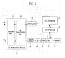
- FIG. 1 is a block diagram showing a constitution of a millimeter-wave frequency modulated continuous wave (FMCW) radar sensor employing a radio frequency (RF) transceiver module according to an exemplary embodiment of the present invention
- FMCW millimeter-wave frequency modulated continuous wave
- RF radio frequency
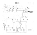
- FIG. 2 is a block diagram of an RF transceiver module according to an exemplary embodiment of the present invention.
- FIG. 1 is a block diagram showing a constitution of a millimeter-wave frequency modulated continuous wave (FMCW) radar sensor employing a radio frequency (RF) transceiver module according to an exemplary embodiment of the present invention.
- FMCW millimeter-wave frequency modulated continuous wave
- RF radio frequency
- the FMCW radar sensor comprises: an RF transceiver module 10 comprising a transceiver antenna unit 11 and an RF transceiver unit 12; an analog circuit 14 connected to an output end of the RF transceiver module 10; an analog-digital (A/D) converter 15 connected to an output end of the analog circuit 14; a fast Fourier transformer (FFT) 16 connected to an output end of the A/D converter 15; a digital signal processor (DSP) 17 connected to an output end of the FFT 16; a display 18 connected to the DSP 17 and displaying information obtained from a received signal; a controller area network (CAN) interface 19 connected between the DSP 17 and an electronic control unit (ECU) processor 20; and a modulator 13 connected to an input end of the RF transceiver module 10 and FMCW-modulating a signal according to control of the DSP 17.
- A/D analog-digital converter 15
- FFT fast Fourier transformer
- DSP digital signal processor
- DSP digital signal processor
- display 18 connected to the D
- the millimeter-wave FMCW radar sensor operates according to the following steps. First, a signal FMCW-modulated by the modulator 13 is carried on a millimeter wave and then amplified at the RF transceiver unit 12 and transmitted through the transceiver antenna unit 11. When the transmitted signal arrives at an object and is reflected back, it is received as a received signal including data of relative velocity and distance between the object and a radar system through the transceiver antenna unit 11. The received signal is converted into a beat signal including the data of relative velocity and distance at the RF transceiver unit 12 of the RF transceiver module 10 and then transferred to the analog circuit 14.
- the A/D converter 15, Fourier-transformed by the FFT 16, and then processed by the DSP 17 processes the transferred signal.
- the DSP 17 drives the modulator 13 to modulate the signal, transfers information to the display 18 to display data on a screen, and transfers the data through the CAN interface 19 to the ECU processor 20.
- the RF transceiver module used in the millimeter-wave FMCW radar sensor shows superior performance in dynamic range, overall detection range, etc. according to the structure.
- the millimeter-wave FMCW radar sensor of the present invention overcomes the drawback of a conventional vehicular FMCW radar structure using a homodyne solution that the dynamic range of a sensor module is reduced by interference between the transmitted signal and the received signal resulting in an insufficient detection range. Consequently, the millimeter-wave FMCW radar sensor of the present invention has improved reception sensitivity in all conditions such as bad weather, day and night, etc.
- the RF transceiver module according to the present invention will be described in detail below.
- FIG. 2 is a block diagram of an RF transceiver module according to an exemplary embodiment of the present invention.
- the RF transceiver module comprises a transmitting antenna 101, a power amplifier 102, a driver amplifier 103, a frequency multiplier 104, a power divider 105, a voltage-controlled oscillator (VCO) 106, a balanced frequency mixer 107, a local oscillator 108, a receiving antenna 109, a first amplifier 110, a low-noise amplifier 111, a down frequency mixer 112, a band-pass filter 113, a second amplifier 114, an IF mixer 115, and an IF amplifier 116.
- the power amplifier 102, the driver amplifier 103 and the frequency multiplier 104 constitute a transmitting unit 117.
- the VCO 106 and the power divider 105 constitute a signal source block 118.
- the local oscillator 108 and the balanced frequency mixer 107 constitute a balanced mixer unit up/down-converting a modulation signal obtained from the transmitting unit 117 and outputting the converted signals to a receiving unit 119.
- the first and second amplifiers 110 and 114, the low-noise amplifier 111, the down frequency mixer 112, the band-pass filter 113, the IF mixer 115, and the IF amplifier 116 constitute the receiving unit 119.
- the second amplifiers 114, the band-pass filter 113, the IF mixer 115, and the IF amplifier 116 constitute the IF unit 120.
- the VCO 106 includes an input modulation frequency fm in a microwave or a millimeter wave fo and outputs it.
- the VCO 106 outputs a modulation signal (fo+fm) that is the sum of the basic wave fo and the modulation frequency fm.
- a signal source having a modulation bandwidth of 100 MHz in a 38.25 GHz band and an output power of 5 dBm can be used as the VCO 106, which is preferably implemented by a monolithic microwave integrated circuit (MMIC) or a Gunn diode.
- the power divider 105 is connected to an output end of the VCO 106, divides power of the modulation signal (fo+fm) output from the VCO 106, and outputs the modulation signal to the transmitting unit 117 and the receiving unit 119.
- the frequency multiplier 104 doubles the modulation signal output from the power divider 105 of the signal source block 118 to a double harmonic and outputs a doubled harmonic signal (2fo+2fm).
- the driver amplifier 103 is connected to an output end of the frequency multiplier 104 and amplifies RF gain of the doubled signal.
- the power amplifier 102 is connected to an output end of the driver amplifier 103 and amplifies the power of the gain-amplified signal.
- the transmission modulation signal output from an output end of the power amplifier 102 is radiated through the transmitting antenna 101.
- the frequency multiplier 104 of the present invention is made of an MMIC and may have an input frequency bandwidth of 38 to 38.5 GHz and an output frequency bandwidth of 76 to 77 GHz.
- the frequency multiplier 104 has superior characteristics of an input frequency suppressing an output frequency and input/output matching.
- the doubled modulation signal is applied to the driver amplifier 103, which is made of an MMIC and operates in a band of, e.g., 76 to 77 GHz, to compensate for conversion loss of the frequency multiplier 104.
- the power amplifier 102 also made of an MMIC, is disposed at the output side of the driver amplifier 103.
- an output power of the power amplifier 102 is 13 dBm so as to satisfy a current 10 dBm standard for output power of a radar sensor.
- An output power of, e.g., 10 dBm is radiated from the transmitting antenna 101.
- a patch array antenna may be used as the transmitting antenna 101.
- the frequency multiplier 104, the driver amplifier 103 and the power amplifier 102 of the transmitting unit 117 may each be made of a separate MMIC or may all be integrated into one MMIC chip.
- the balanced frequency mixer 107 up and down-converts the modulation signal (fo+fm) output from the power divider 105 of the signal source block 118 using a local oscillation signal fa generated by the local oscillator 108, and outputs a converted first signal (fo+fm+fa) and a converted second signal (fo+fm-fa) to the two different amplifiers 110 and 114 of the receiving unit 119, respectively.
- the down frequency mixer 112 mixes a received signal (2fo+fb+2fa) with the first signal transferred through the first amplifier 110 to a local terminal, and outputs a mixed third signal (fo+fb-fa+fm) to an intermediate frequency (IF) block 120.
- IF intermediate frequency
- the received signal is received at the receiving antenna 109 and then transferred to an RF terminal of the down frequency mixer 112 through the low-noise amplifier 111.
- the IF mixer 115 mixes the third signal passed through the band-pass filter 113 to pass only a desired frequency with the second signal transferred through the second amplifier 114 to a local terminal, and outputs the mixed signal to an IF output terminal.
- the IF amplifier 116 is connected to an output end of the IF mixer 115, amplifies a beat signal fb output from the IF mixer 115, and transfers the amplified beat signal to a DSP of a radar sensor.
- the beat signal corresponds to deviation in the received signal resulting from the Doppler effect.
- the first amplifier 110, the low-noise amplifier 111 and the down frequency mixer 112 of the receiving unit 119 may each be made of a separate MMIC or integrated into one MMIC chip. And, an RF band-pass filter passing only frequencies of a desired band and fabricated in a waveguide form may be used as the band-pass filter 113 of the receiving unit 119.
- a modulation signal of the transmitting unit 117 is not directly transferred to the down frequency mixer 112 of the receiving unit 119. Instead, in order to separately use the transmission modulation signal and the local oscillation signal of the receiving unit 119, the local oscillation signal of the local oscillator 108 and the modulation signal output from the VCO 106 are up and down-converted by the balanced frequency mixer 107, and the converted first and second signals are transferred to the receiving unit 119.
- the first and second signals transferred to the receiving unit 119 are respectively passed through the two different amplifiers 110 and 114 and applied to the LO terminals of the two frequency mixers 112 and 115 of the receiving unit 119 and the IF block 120.
- a modulation signal of the transmitting unit 117 is isolated from a received signal and thus not affected by interference from the received signal in the RF transceiver module.
- a pair of frequencies generated by balance-mixing the local oscillation signal fa generated by the local oscillator 108 with a modulation signal output from the VCO 106 of the transmitting unit 117 are applied to the two frequency mixers 112 and 115 of the receiving unit 119.
- a modulation signal output from a VCO of a transmitting unit is directly used, signal interference occurs between the transmitting unit and a receiving unit. The present invention solves this problem and improves separation of transmission and reception.
- a modulation signal (fo+fm) is 38.25 GHz and a transmitted signal (2fo+2fm) is 76.5 GHz.
- fb is a beat frequency on the order of MHz corresponding to a frequency deviation obtained when a transmitted signal is reflected from an obstacle.
- a received signal of (76.5 GHz + fb) is input to the down frequency mixer, down-converted by the first signal (fo+fm+fa) into a signal of (37.25 GHz + fb), and converted by the second signal (fo+fm-fa) of 37.25 GHz at the IF mixer.
- the signal fb is amplified at the IF amplifier and transferred as the beat signal to a DSP.
- the local oscillation signal fa is 37.25 GHz
- a modulation signal (fo+fm) is 38.25 GHz
- a transmitted signal (2fo+2fm) is 76.5 GHz.
- a received signal of (76.5 GHz + fb) is input to the down frequency mixer, down-converted by the first signal (fo+fm+fa) into a signal of (1 GHz + fb), and converted by the second signal (fo+fm-fa) of 1 GHz at the IF mixer.
- the signal fb is amplified at the IF amplifier and transferred as a beat signal to the DSP.
- the present invention can solve the problem of an adjacent signal spectrum characteristic, that is, deterioration of reception sensitivity occurring because a signal transferred from a transmitting unit to a receiving unit is somewhat higher than a signal received through a receiving antenna, in a conventional RF transceiver.
- the present invention can improve isolation of an RF transceiver module.
- At least one of a parabolic antenna, a lens antenna, a microstrip patch array antenna and a horn antenna, as well as a patch array antenna may be selected and used.
- an RF transceiver module for a millimeter-wave radar sensor can solve the problem of reception sensitivity deterioration occurring in a conventional RF transceiver module using a homodyne solution.
- the present invention can improve the reception sensitivity of an RF transceiver module for a millimeter-wave radar sensor by about 20 to 30 dB.
- the RF transceiver module using an MMIC and a heterodyne solution can be easily applied to a 77 GHz-band radar sensor for preventing automobile collisions, an adaptive automatic cruise control (ACC) system using the sensor, etc., and can improve performance of a system employing it.
- ACC adaptive automatic cruise control
Landscapes
- Engineering & Computer Science (AREA)
- Radar, Positioning & Navigation (AREA)
- Remote Sensing (AREA)
- Physics & Mathematics (AREA)
- Computer Networks & Wireless Communication (AREA)
- General Physics & Mathematics (AREA)
- Signal Processing (AREA)
- Electromagnetism (AREA)
- Radar Systems Or Details Thereof (AREA)
- Transceivers (AREA)
Abstract
Description
- This application claims priority to and the benefit of
Korean Patent Application Nos. 2005-119501, filed December 7, 2005 2006-50820, filed June 7, 2006 - The present invention relates to a radio frequency (RF) transceiver module having an improved connection structure between main components and capable of improving reception sensitivity, and a millimeter-wave frequency modulated continuous wave (FMCW) radar sensor using the RF transceiver.
- In general, various types of sensors employed in motor vehicles have been devised based on technologies such as ultrasonic radar, image sensing, laser sensing, and millimeter-wave radar. Ultrasonic radar sensors are small and relatively inexpensive but have poor reception sensitivity. Thus, they are appropriate for short-range warning but not for detecting obstacles during high-speed travel as their operation is affected by the surrounding environment. Image sensors cannot easily detect obstacles in real time due to the complex image processing, etc. involved, and exhibit poor performance in bad weather. Laser sensors have been developed to detect obstacles at long range using a near-infrared laser, but exhibit poor performance in bad weather such as fog, rain, etc. On the other hand, millimeter-wave radar detectors show little difference in performance between day and night and in varying weather conditions, and thus are known to be the most appropriate technology for use in motor vehicles.
- A millimeter-wave FMCW radar sensor generally comprises an RF transceiver module, a digital signal processing (DSP) unit for signal processing, a controller area network (CAN) interface unit, a display unit and a processor. And, the RF transceiver module comprises a voltage-controlled oscillator (VCO) generating a FMCW-modulated signal, an amplifier amplifying a millimeter-wave output signal of the VCO, a transmitting antenna transmitting the amplified signal, a receiving antenna receiving a signal reflected from an object, a low-noise amplifier amplifying the received signal, a mixer detecting a beat signal carrying information on a relative velocity of the object and a distance from the object, and an intermediate frequency (IF) unit processing the beat signal.
- Meanwhile, an RF transceiver module for a millimeter-wave radar sensor using a monolithic microwave integrated circuit (MMIC) is a core component disposed in the front part of the radar sensor and managing wireless communication. Reception sensitivity of the RF transceiver module is a very important factor determining the range of the radar sensor. Therefore, in order to increase the range of the RF transceiver module, reception sensitivity of the RF transceiver module must be improved.
- However, in a conventional RF transceiver module using a homodyne solution, a transmission modulation signal affects a received signal and thus an isolation characteristic of a receiving unit deteriorates. Consequently, high-sensitivity reception in a radar sensor becomes impossible.
- The present invention is directed to a structure for improving reception sensitivity and separation of a transmitted signal and a received signal without using a conventional homodyne solution to construct a radio frequency (RF) transceiver module of a vehicle radar sensor. More specifically, the RF transceiver module used in a millimeter-wave frequency modulated continuous wave (FMCW) radar sensor basically comprises: a voltage-controlled oscillator (VCO); a transmitting unit comprising a frequency multiplier, a driver amplifier, a power amplifier and a frequency division circuit; and a receiving unit comprising a low-noise amplifier, a down frequency mixer, a filter and an intermediate frequency (IF) amplifier. The RF transceiver module uses a local oscillator (LO) generating a signal fa and a mixer balance-mixing the signal fa with a modulation output signal (fo+fm) output from the VCO of the transmitting unit, thereby inputting a first signal (fo+fm+fa) and a second signal (fo+fm-fa) output from the mixer to two frequency mixers of the receiving unit. Thus, the RF transceiver module can solve the problem of signal interference between the transmitting unit and the receiving unit caused in the conventional art when a modulation signal output from a VCO of the transmitting unit is directly used, and improve signal reception.
- The present invention is also directed to an apparatus for a millimeter-wave FMCW radar sensor using the above-described RF transceiver module.
- One aspect of the present invention provides an RF transceiver module for a radar sensor, the RF transceiver module comprising: a transmitting unit having a power divider dividing a modulation signal (fo+fm) generated by a VCO, doubling and amplifying the modulation signal, and radiating the amplified modulation signal (2fo+2fm) through a transmitting antenna; a balanced mixer unit up/down-converting the modulation signal output from the power divider using a local oscillation signal fa output from a local oscillator and outputting a converted first signal (fo+fm+fa) and a converted second signal (fo+fm-fa); and a receiving unit down-mixing a signal (2fo+fb+2fm) received through a receiving antenna with the first signal using a down frequency mixer, mixing a down-mixed third signal (fo+fb-fa+fm) with the second signal using an IF mixer, and outputting the mixed signal fb.
- The above and other objects, features and advantages of the present invention will become more apparent to those of ordinary skill in the art by describing in detail exemplary embodiments thereof with reference to the attached drawings in which:
- FIG. 1 is a block diagram showing a constitution of a millimeter-wave frequency modulated continuous wave (FMCW) radar sensor employing a radio frequency (RF) transceiver module according to an exemplary embodiment of the present invention; and
- FIG. 2 is a block diagram of an RF transceiver module according to an exemplary embodiment of the present invention.
- Hereinafter, exemplary embodiments of the present invention will be described in detail. However, the present invention is not limited to the embodiments disclosed below, but can be implemented in various forms. Those of ordinary skill in the art describe the following embodiments in order for this disclosure to be complete and enabling of practice of the invention.
- FIG. 1 is a block diagram showing a constitution of a millimeter-wave frequency modulated continuous wave (FMCW) radar sensor employing a radio frequency (RF) transceiver module according to an exemplary embodiment of the present invention.
- Referring to FIG. 1, the FMCW radar sensor according to this exemplary embodiment comprises: an
RF transceiver module 10 comprising atransceiver antenna unit 11 and anRF transceiver unit 12; ananalog circuit 14 connected to an output end of theRF transceiver module 10; an analog-digital (A/D)converter 15 connected to an output end of theanalog circuit 14; a fast Fourier transformer (FFT) 16 connected to an output end of the A/D converter 15; a digital signal processor (DSP) 17 connected to an output end of theFFT 16; adisplay 18 connected to theDSP 17 and displaying information obtained from a received signal; a controller area network (CAN)interface 19 connected between theDSP 17 and an electronic control unit (ECU)processor 20; and amodulator 13 connected to an input end of theRF transceiver module 10 and FMCW-modulating a signal according to control of theDSP 17. - The millimeter-wave FMCW radar sensor operates according to the following steps. First, a signal FMCW-modulated by the
modulator 13 is carried on a millimeter wave and then amplified at theRF transceiver unit 12 and transmitted through thetransceiver antenna unit 11. When the transmitted signal arrives at an object and is reflected back, it is received as a received signal including data of relative velocity and distance between the object and a radar system through thetransceiver antenna unit 11. The received signal is converted into a beat signal including the data of relative velocity and distance at theRF transceiver unit 12 of theRF transceiver module 10 and then transferred to theanalog circuit 14. Subsequently, the A/D converter 15, Fourier-transformed by theFFT 16, and then processed by theDSP 17 processes the transferred signal. The DSP 17 drives themodulator 13 to modulate the signal, transfers information to thedisplay 18 to display data on a screen, and transfers the data through theCAN interface 19 to theECU processor 20. - The RF transceiver module used in the millimeter-wave FMCW radar sensor shows superior performance in dynamic range, overall detection range, etc. according to the structure. Thus, the millimeter-wave FMCW radar sensor of the present invention overcomes the drawback of a conventional vehicular FMCW radar structure using a homodyne solution that the dynamic range of a sensor module is reduced by interference between the transmitted signal and the received signal resulting in an insufficient detection range. Consequently, the millimeter-wave FMCW radar sensor of the present invention has improved reception sensitivity in all conditions such as bad weather, day and night, etc. The RF transceiver module according to the present invention will be described in detail below.
- FIG. 2 is a block diagram of an RF transceiver module according to an exemplary embodiment of the present invention.
- Referring to FIG. 2, the RF transceiver module according to an exemplary embodiment of the present invention comprises a
transmitting antenna 101, apower amplifier 102, adriver amplifier 103, afrequency multiplier 104, apower divider 105, a voltage-controlled oscillator (VCO) 106, a balancedfrequency mixer 107, alocal oscillator 108, areceiving antenna 109, afirst amplifier 110, a low-noise amplifier 111, adown frequency mixer 112, a band-pass filter 113, asecond amplifier 114, anIF mixer 115, and anIF amplifier 116. Thepower amplifier 102, thedriver amplifier 103 and thefrequency multiplier 104 constitute a transmittingunit 117. The VCO 106 and thepower divider 105 constitute asignal source block 118. Thelocal oscillator 108 and thebalanced frequency mixer 107 constitute a balanced mixer unit up/down-converting a modulation signal obtained from the transmittingunit 117 and outputting the converted signals to areceiving unit 119. The first andsecond amplifiers noise amplifier 111, thedown frequency mixer 112, the band-pass filter 113, theIF mixer 115, and theIF amplifier 116 constitute thereceiving unit 119. Thesecond amplifiers 114, the band-pass filter 113, theIF mixer 115, and theIF amplifier 116 constitute theIF unit 120. - In the
signal source block 118, theVCO 106 includes an input modulation frequency fm in a microwave or a millimeter wave fo and outputs it. In other words, theVCO 106 outputs a modulation signal (fo+fm) that is the sum of the basic wave fo and the modulation frequency fm. For example, a signal source having a modulation bandwidth of 100 MHz in a 38.25 GHz band and an output power of 5 dBm can be used as the VCO 106, which is preferably implemented by a monolithic microwave integrated circuit (MMIC) or a Gunn diode. Thepower divider 105 is connected to an output end of theVCO 106, divides power of the modulation signal (fo+fm) output from theVCO 106, and outputs the modulation signal to the transmittingunit 117 and thereceiving unit 119. - In the transmitting
unit 117, thefrequency multiplier 104 doubles the modulation signal output from thepower divider 105 of thesignal source block 118 to a double harmonic and outputs a doubled harmonic signal (2fo+2fm). Thedriver amplifier 103 is connected to an output end of thefrequency multiplier 104 and amplifies RF gain of the doubled signal. Thepower amplifier 102 is connected to an output end of thedriver amplifier 103 and amplifies the power of the gain-amplified signal. The transmission modulation signal output from an output end of thepower amplifier 102 is radiated through the transmittingantenna 101. - The
frequency multiplier 104 of the present invention is made of an MMIC and may have an input frequency bandwidth of 38 to 38.5 GHz and an output frequency bandwidth of 76 to 77 GHz. Preferably, thefrequency multiplier 104 has superior characteristics of an input frequency suppressing an output frequency and input/output matching. The doubled modulation signal is applied to thedriver amplifier 103, which is made of an MMIC and operates in a band of, e.g., 76 to 77 GHz, to compensate for conversion loss of thefrequency multiplier 104. Thepower amplifier 102, also made of an MMIC, is disposed at the output side of thedriver amplifier 103. Preferably, an output power of thepower amplifier 102 is 13 dBm so as to satisfy a current 10 dBm standard for output power of a radar sensor. An output power of, e.g., 10 dBm is radiated from the transmittingantenna 101. Here, a patch array antenna may be used as the transmittingantenna 101. Thefrequency multiplier 104, thedriver amplifier 103 and thepower amplifier 102 of the transmittingunit 117 may each be made of a separate MMIC or may all be integrated into one MMIC chip. - In the balanced mixer unit, the
balanced frequency mixer 107 up and down-converts the modulation signal (fo+fm) output from thepower divider 105 of the signal source block 118 using a local oscillation signal fa generated by thelocal oscillator 108, and outputs a converted first signal (fo+fm+fa) and a converted second signal (fo+fm-fa) to the twodifferent amplifiers unit 119, respectively. - In the receiving
unit 119, thedown frequency mixer 112 mixes a received signal (2fo+fb+2fa) with the first signal transferred through thefirst amplifier 110 to a local terminal, and outputs a mixed third signal (fo+fb-fa+fm) to an intermediate frequency (IF) block 120. Here, the received signal is received at the receivingantenna 109 and then transferred to an RF terminal of thedown frequency mixer 112 through the low-noise amplifier 111. - In the
IF block 120, theIF mixer 115 mixes the third signal passed through the band-pass filter 113 to pass only a desired frequency with the second signal transferred through thesecond amplifier 114 to a local terminal, and outputs the mixed signal to an IF output terminal. TheIF amplifier 116 is connected to an output end of theIF mixer 115, amplifies a beat signal fb output from theIF mixer 115, and transfers the amplified beat signal to a DSP of a radar sensor. Here, the beat signal corresponds to deviation in the received signal resulting from the Doppler effect. - The
first amplifier 110, the low-noise amplifier 111 and thedown frequency mixer 112 of the receivingunit 119 may each be made of a separate MMIC or integrated into one MMIC chip. And, an RF band-pass filter passing only frequencies of a desired band and fabricated in a waveguide form may be used as the band-pass filter 113 of the receivingunit 119. - In the present invention, unlike a conventional transceiver using a homodyne solution, a modulation signal of the transmitting
unit 117 is not directly transferred to thedown frequency mixer 112 of the receivingunit 119. Instead, in order to separately use the transmission modulation signal and the local oscillation signal of the receivingunit 119, the local oscillation signal of thelocal oscillator 108 and the modulation signal output from theVCO 106 are up and down-converted by thebalanced frequency mixer 107, and the converted first and second signals are transferred to the receivingunit 119. Here, in order to compensate for conversion loss of thebalanced frequency mixer 107, the first and second signals transferred to the receivingunit 119 are respectively passed through the twodifferent amplifiers frequency mixers unit 119 and theIF block 120. According to this constitution, a modulation signal of the transmittingunit 117 is isolated from a received signal and thus not affected by interference from the received signal in the RF transceiver module. - In other words, in the present invention, a pair of frequencies generated by balance-mixing the local oscillation signal fa generated by the
local oscillator 108 with a modulation signal output from theVCO 106 of the transmittingunit 117 are applied to the twofrequency mixers unit 119. On the other hand, conventionally, when a modulation signal output from a VCO of a transmitting unit is directly used, signal interference occurs between the transmitting unit and a receiving unit. The present invention solves this problem and improves separation of transmission and reception. Since differences between the transmission modulation signal (2fo+2fm) of the transmittingunit 117, the first signal (fo+fm+fa) output from thebalanced frequency mixer 107, and the third signal (fo+fb-fa+fm) down-converted by the first signal are very large, interference between signals of the transmitting unit and the receiving unit is significantly reduced. Consequently, system performance can be improved by increasing the dynamic range of the receiving unit and the detection range of the radar sensor. - For example, when the local oscillation signal fa is 1 GHz, a modulation signal (fo+fm) is 38.25 GHz and a transmitted signal (2fo+2fm) is 76.5 GHz. fb is a beat frequency on the order of MHz corresponding to a frequency deviation obtained when a transmitted signal is reflected from an obstacle. In this case, a received signal of (76.5 GHz + fb) is input to the down frequency mixer, down-converted by the first signal (fo+fm+fa) into a signal of (37.25 GHz + fb), and converted by the second signal (fo+fm-fa) of 37.25 GHz at the IF mixer. Then, the signal fb is amplified at the IF amplifier and transferred as the beat signal to a DSP.
- For an additional example, it is assumed that the local oscillation signal fa is 37.25 GHz, a modulation signal (fo+fm) is 38.25 GHz and a transmitted signal (2fo+2fm) is 76.5 GHz. In this case, a received signal of (76.5 GHz + fb) is input to the down frequency mixer, down-converted by the first signal (fo+fm+fa) into a signal of (1 GHz + fb), and converted by the second signal (fo+fm-fa) of 1 GHz at the IF mixer. Then, the signal fb is amplified at the IF amplifier and transferred as a beat signal to the DSP.
- The present invention can solve the problem of an adjacent signal spectrum characteristic, that is, deterioration of reception sensitivity occurring because a signal transferred from a transmitting unit to a receiving unit is somewhat higher than a signal received through a receiving antenna, in a conventional RF transceiver. In other words, the present invention can improve isolation of an RF transceiver module.
- As the above-mentioned transmitting antenna and receiving antenna, at least one of a parabolic antenna, a lens antenna, a microstrip patch array antenna and a horn antenna, as well as a patch array antenna, may be selected and used.
- As described above, an RF transceiver module for a millimeter-wave radar sensor according to the present invention can solve the problem of reception sensitivity deterioration occurring in a conventional RF transceiver module using a homodyne solution. In other words, the present invention can improve the reception sensitivity of an RF transceiver module for a millimeter-wave radar sensor by about 20 to 30 dB. In addition, the RF transceiver module using an MMIC and a heterodyne solution can be easily applied to a 77 GHz-band radar sensor for preventing automobile collisions, an adaptive automatic cruise control (ACC) system using the sensor, etc., and can improve performance of a system employing it.
- While the invention has been shown and described with reference to certain exemplary embodiments thereof, it will be understood by those skilled in the art that various changes in form and details may be made therein without departing from the spirit and scope of the invention as defined by the appended claims.
Claims (12)
- A radio frequency (RF) transceiver module for a radar sensor, comprising:a transmitting unit having a power divider dividing a modulation signal generated by a voltage-controlled oscillator (VCO), amplifying the modulation signal, and radiating the amplified modulation signal through a transmitting antenna;a balanced mixer unit up/down-converting the modulation signal output from the power divider using a local oscillation signal output from a local oscillator, and outputting converted first and second signals; anda receiving unit down-mixing an external signal received through a receiving antenna with the first signal using a down frequency mixer, mixing a down-mixed third signal with the second signal using an intermediate frequency (IF) mixer, and outputting the mixed signal.
- The RF transceiver module of claim 1, further comprising:first and second amplifiers respectively connected between a balanced frequency mixer included in the balanced mixer unit and the down frequency mixer and between the balanced frequency mixer and the IF mixer.
- The RF transceiver module of claim 2, wherein the transmitting unit comprises:a frequency multiplier for doubling the modulation signal output from the power divider; anda driver amplifier and a power amplifier for amplifying an output signal of the frequency multiplier and transferring the amplified output signal to the transmitting antenna,wherein the frequency multiplier, the driver amplifier and the power amplifier are respectively made of monolithic microwave integrated circuits (MMICs).
- The RF transceiver module of claim 2 or 3, wherein the receiving unit comprises:a low-noise amplifier connected between the receiving antenna and the down frequency mixer,wherein the low-noise amplifier, the first and second amplifiers, and the down frequency mixer are respectively made of MMICs.
- The RF transceiver module of claim 2, wherein the transmitting unit comprises a frequency multiplier for doubling the modulation signal output from the power divider; and
a driver amplifier and a power amplifier for amplifying an output signal of the frequency multiplier and transferring the amplified output signal to the transmitting antenna,
wherein the frequency multiplier, the driver amplifier and the power amplifier are integrated into one MMIC chip. - The RF transceiver module of claim 2 or 5, wherein the receiving unit comprises:a low-noise amplifier connected between the receiving antenna and the down frequency mixer,wherein the low-noise amplifier, the first and second amplifiers, and the down frequency mixer are integrated into one MMIC chip.
- The RF transceiver module of one of claims 1 to 6, further comprising:a band-pass filter connected between the down frequency mixer and the IF mixer.
- The RF transceiver module of one of claims 1 to 7, further comprising:an IF amplifier for amplifying a signal output from the IF mixer and outputting the amplified signal as a beat signal.
- A millimeter-wave frequency modulated continuous wave (FMCW) radar sensor comprising an RF transceiver module, wherein the RF transceiver module comprises:a transmitting unit having a power divider dividing a modulation signal generated by a voltage-controlled oscillator (VCO), amplifying the modulation signal, and radiating the amplified modulation signal through a transmitting antenna;a balanced mixer unit up/down-converting the modulation signal output from the power divider using a local oscillation signal output from a local oscillator and outputting converted first and second signals; anda receiving unit down-mixing an external signal received through a receiving antenna with the first signal using a down frequency mixer, mixing a down-mixed third signal with the second signal using an intermediate frequency (IF) mixer, and outputting the mixed signal.
- The millimeter-wave FMCW radar sensor of claim 9, wherein the RF transceiver module further comprises:first and second amplifiers respectively connected between a balanced frequency mixer included in the balanced mixer unit and the down frequency mixer and between the balanced frequency mixer and the IF mixer.
- The millimeter-wave FMCW radar sensor of claim 9, wherein the RF transceiver module further comprises:a band-pass filter connected between the down frequency mixer and the IF mixer.
- The millimeter-wave FMCW radar sensor of claim 9, wherein the RF transceiver module further comprises:an IF amplifier for amplifying a signal output from the IF mixer and outputting the amplified signal as a beat signal.
Applications Claiming Priority (2)
| Application Number | Priority Date | Filing Date | Title |
|---|---|---|---|
| KR20050119051 | 2005-12-07 | ||
| KR1020060050820A KR100751065B1 (en) | 2005-12-07 | 2006-06-07 | RF transceiver module and millimeterwave FMCW radar sensor using the same |
Publications (2)
| Publication Number | Publication Date |
|---|---|
| EP1795914A1 true EP1795914A1 (en) | 2007-06-13 |
| EP1795914B1 EP1795914B1 (en) | 2008-09-24 |
Family
ID=37769838
Family Applications (1)
| Application Number | Title | Priority Date | Filing Date |
|---|---|---|---|
| EP06125482A Not-in-force EP1795914B1 (en) | 2005-12-07 | 2006-12-06 | RF transceiver module and millimeter-wave FMCW radar sensor using the same |
Country Status (4)
| Country | Link |
|---|---|
| EP (1) | EP1795914B1 (en) |
| JP (1) | JP4677396B2 (en) |
| AT (1) | ATE409318T1 (en) |
| DE (1) | DE602006002865D1 (en) |
Cited By (13)
| Publication number | Priority date | Publication date | Assignee | Title |
|---|---|---|---|---|
| CN102752010A (en) * | 2011-04-21 | 2012-10-24 | 沈阳中科微电子有限公司 | Transceiving module used for communication base stations |
| US9285461B2 (en) | 2013-03-12 | 2016-03-15 | Nokia Technologies Oy | Steerable transmit, steerable receive frequency modulated continuous wave radar transceiver |
| CN105824020A (en) * | 2016-03-12 | 2016-08-03 | 浙江大学 | Subcarrier-modulation-based continuous wave Doppler radar sensor and motion demodulation method |
| WO2018023823A1 (en) * | 2016-08-03 | 2018-02-08 | 华讯方舟科技有限公司 | Millimeter wave imaging apparatus |
| CN108631795A (en) * | 2018-05-16 | 2018-10-09 | 广州天空概念通信科技有限公司 | A kind of unmanned plane counter system of frequency dividing cooperation |
| US10359496B2 (en) | 2015-08-10 | 2019-07-23 | Viasat, Inc. | Satellite antenna with sensor for line-of-sight detection |
| CN110824475A (en) * | 2019-12-25 | 2020-02-21 | 舟山千眼传感技术有限公司 | A Radar for Monitoring Vehicle Queuing Status at Intersections |
| CN110934585A (en) * | 2019-11-29 | 2020-03-31 | 维沃移动通信有限公司 | A monitoring method and electronic device |
| CN112019232A (en) * | 2020-02-28 | 2020-12-01 | 加特兰微电子科技(上海)有限公司 | Signal transmitting and receiving device, electronic device and equipment |
| CN115396996A (en) * | 2022-10-25 | 2022-11-25 | 深圳芯盛思技术有限公司 | Radio frequency intermittent working chopping power-saving system, method and chip |
| CN117741639A (en) * | 2023-12-20 | 2024-03-22 | 湖南众天云科技有限公司 | Millimeter wave radar device with automatic zooming function and control method |
| CN118157699A (en) * | 2024-05-09 | 2024-06-07 | 成都安普利电子有限责任公司 | 4-Channel broadband variable-frequency receiving module |
| CN118868799A (en) * | 2024-09-23 | 2024-10-29 | 成都安普利电子有限责任公司 | A 2GHz bandwidth receiving frequency conversion module |
Families Citing this family (2)
| Publication number | Priority date | Publication date | Assignee | Title |
|---|---|---|---|---|
| US8509335B2 (en) | 2009-03-10 | 2013-08-13 | Kabushiki Kaisha Toshiba | Array antenna apparatus and micro wave transceiver module |
| KR20240043368A (en) * | 2022-09-27 | 2024-04-03 | 엘지전자 주식회사 | Frequency-Modulated Continuous Wave radar and electronic device including the same |
Citations (4)
| Publication number | Priority date | Publication date | Assignee | Title |
|---|---|---|---|---|
| US3197773A (en) * | 1962-04-19 | 1965-07-27 | Sperry Rand Corp | Frequency modulated continuous wave navigation radar |
| US20020180632A1 (en) * | 2000-09-26 | 2002-12-05 | Osamu Isaji | Fm-cw radar system |
| US20040012517A1 (en) * | 2002-07-17 | 2004-01-22 | Ramzi Abou-Jaoude | Integrated multiple-up/down conversion radar test system |
| US20040150548A1 (en) * | 2003-02-03 | 2004-08-05 | Walmsley Prescott A. | Linear frequency modulation superimposed on double sideband diplex radar |
Family Cites Families (4)
| Publication number | Priority date | Publication date | Assignee | Title |
|---|---|---|---|---|
| JPS52124172U (en) * | 1976-03-17 | 1977-09-21 | ||
| JPS62179681A (en) * | 1986-02-01 | 1987-08-06 | Tech Res & Dev Inst Of Japan Def Agency | Phase synchronous tracking radar |
| JP3205847B2 (en) * | 1993-06-16 | 2001-09-04 | 日本無線株式会社 | Radar system using spread spectrum system |
| JPH0972959A (en) * | 1995-09-05 | 1997-03-18 | Mitsubishi Electric Corp | FM-CW radar |
-
2006
- 2006-12-06 DE DE602006002865T patent/DE602006002865D1/en active Active
- 2006-12-06 EP EP06125482A patent/EP1795914B1/en not_active Not-in-force
- 2006-12-06 AT AT06125482T patent/ATE409318T1/en not_active IP Right Cessation
- 2006-12-07 JP JP2006330714A patent/JP4677396B2/en not_active Expired - Fee Related
Patent Citations (4)
| Publication number | Priority date | Publication date | Assignee | Title |
|---|---|---|---|---|
| US3197773A (en) * | 1962-04-19 | 1965-07-27 | Sperry Rand Corp | Frequency modulated continuous wave navigation radar |
| US20020180632A1 (en) * | 2000-09-26 | 2002-12-05 | Osamu Isaji | Fm-cw radar system |
| US20040012517A1 (en) * | 2002-07-17 | 2004-01-22 | Ramzi Abou-Jaoude | Integrated multiple-up/down conversion radar test system |
| US20040150548A1 (en) * | 2003-02-03 | 2004-08-05 | Walmsley Prescott A. | Linear frequency modulation superimposed on double sideband diplex radar |
Cited By (18)
| Publication number | Priority date | Publication date | Assignee | Title |
|---|---|---|---|---|
| CN102752010B (en) * | 2011-04-21 | 2016-06-15 | 沈阳中科微电子有限公司 | A kind of transceiver module for the base station that communicates |
| CN102752010A (en) * | 2011-04-21 | 2012-10-24 | 沈阳中科微电子有限公司 | Transceiving module used for communication base stations |
| US9285461B2 (en) | 2013-03-12 | 2016-03-15 | Nokia Technologies Oy | Steerable transmit, steerable receive frequency modulated continuous wave radar transceiver |
| US10359496B2 (en) | 2015-08-10 | 2019-07-23 | Viasat, Inc. | Satellite antenna with sensor for line-of-sight detection |
| CN105824020A (en) * | 2016-03-12 | 2016-08-03 | 浙江大学 | Subcarrier-modulation-based continuous wave Doppler radar sensor and motion demodulation method |
| CN105824020B (en) * | 2016-03-12 | 2018-06-12 | 浙江大学 | The continuous wave Doppler radar sensor of subcarrier modulation and movement demodulation method |
| US11156710B2 (en) | 2016-08-03 | 2021-10-26 | China Communication Technology Co., Ltd. | Millimeter wave imaging apparatus |
| WO2018023823A1 (en) * | 2016-08-03 | 2018-02-08 | 华讯方舟科技有限公司 | Millimeter wave imaging apparatus |
| CN108631795A (en) * | 2018-05-16 | 2018-10-09 | 广州天空概念通信科技有限公司 | A kind of unmanned plane counter system of frequency dividing cooperation |
| CN110934585A (en) * | 2019-11-29 | 2020-03-31 | 维沃移动通信有限公司 | A monitoring method and electronic device |
| CN110824475A (en) * | 2019-12-25 | 2020-02-21 | 舟山千眼传感技术有限公司 | A Radar for Monitoring Vehicle Queuing Status at Intersections |
| CN112019232A (en) * | 2020-02-28 | 2020-12-01 | 加特兰微电子科技(上海)有限公司 | Signal transmitting and receiving device, electronic device and equipment |
| CN115396996A (en) * | 2022-10-25 | 2022-11-25 | 深圳芯盛思技术有限公司 | Radio frequency intermittent working chopping power-saving system, method and chip |
| CN115396996B (en) * | 2022-10-25 | 2023-02-14 | 深圳芯盛思技术有限公司 | Chopped wave power-saving system and method for intermittent work of radio frequency |
| CN117741639A (en) * | 2023-12-20 | 2024-03-22 | 湖南众天云科技有限公司 | Millimeter wave radar device with automatic zooming function and control method |
| CN117741639B (en) * | 2023-12-20 | 2024-11-05 | 湖南众天云科技有限公司 | Millimeter wave radar device with automatic zooming function and control method |
| CN118157699A (en) * | 2024-05-09 | 2024-06-07 | 成都安普利电子有限责任公司 | 4-Channel broadband variable-frequency receiving module |
| CN118868799A (en) * | 2024-09-23 | 2024-10-29 | 成都安普利电子有限责任公司 | A 2GHz bandwidth receiving frequency conversion module |
Also Published As
| Publication number | Publication date |
|---|---|
| EP1795914B1 (en) | 2008-09-24 |
| ATE409318T1 (en) | 2008-10-15 |
| JP4677396B2 (en) | 2011-04-27 |
| JP2007155741A (en) | 2007-06-21 |
| DE602006002865D1 (en) | 2008-11-06 |
Similar Documents
| Publication | Publication Date | Title |
|---|---|---|
| JP3154829B2 (en) | Compact and versatile integrated millimeter-wave radar sensor | |
| JP2981312B2 (en) | FM-CW radar device | |
| US5495255A (en) | FM radar system | |
| CN102866387B (en) | Millimeter wave frequency modulated continuous wave (FMCW) two-unit phased array distance and velocity measurement monolithic radar transceiver | |
| EP1795914B1 (en) | RF transceiver module and millimeter-wave FMCW radar sensor using the same | |
| US20080297400A1 (en) | Monostatic Planar Multi-Beam Radar Sensor | |
| JPH03505636A (en) | Short range radar transceiver using FET oscillator | |
| CN119154895B (en) | Signal transmission links and methods, transceiver links, integrated circuits and electromagnetic wave devices | |
| KR101167906B1 (en) | Radar system for vehicle and method for detecting targets using radar sysem | |
| JP2021021576A (en) | Radar device | |
| KR100751065B1 (en) | RF transceiver module and millimeterwave FMCW radar sensor using the same | |
| US20080117099A1 (en) | Radar System Including a Heterodyne Mixer for the Improved Detection of Short-Range Signals | |
| Yamano et al. | 76GHz millimeter wave automobile radar using single chip MMIC | |
| Almorox-Gonzalez et al. | Millimeter-wave sensor with FMICW capabilities for medium-range high-resolution radars | |
| EP1184678A2 (en) | Radar transceiver | |
| JP2004245647A (en) | Short-range radar device and vehicle equipped with short-range radar device | |
| JPH0933643A (en) | Aperture antenna, antenna drive circuit, and radar device | |
| JP7821863B2 (en) | electronic equipment | |
| JPH11183600A (en) | Radar equipment | |
| JPH08304531A (en) | FM-CW radar | |
| US20250231274A1 (en) | Extended Virtual Array In An Automotive MIMO Radar | |
| Girma | Concepts for Short Range Millimeter-wave Miniaturized Radar Systems with Built-in Self-Test | |
| JPH07311261A (en) | Time division multiplexing multi-channel radar system | |
| KR20250062300A (en) | Baseband system for long-range detection radar and method of operation thereof | |
| JP2001074829A (en) | Transceiver for FM pulse Doppler radar |
Legal Events
| Date | Code | Title | Description |
|---|---|---|---|
| PUAI | Public reference made under article 153(3) epc to a published international application that has entered the european phase |
Free format text: ORIGINAL CODE: 0009012 |
|
| AK | Designated contracting states |
Kind code of ref document: A1 Designated state(s): AT BE BG CH CY CZ DE DK EE ES FI FR GB GR HU IE IS IT LI LT LU LV MC NL PL PT RO SE SI SK TR |
|
| AX | Request for extension of the european patent |
Extension state: AL BA HR MK YU |
|
| 17P | Request for examination filed |
Effective date: 20070723 |
|
| AKX | Designation fees paid |
Designated state(s): AT BE BG CH CY CZ DE DK EE ES FI FR GB GR HU IE IS IT LI LT LU LV MC NL PL PT RO SE SI SK TR |
|
| GRAP | Despatch of communication of intention to grant a patent |
Free format text: ORIGINAL CODE: EPIDOSNIGR1 |
|
| GRAS | Grant fee paid |
Free format text: ORIGINAL CODE: EPIDOSNIGR3 |
|
| GRAA | (expected) grant |
Free format text: ORIGINAL CODE: 0009210 |
|
| AK | Designated contracting states |
Kind code of ref document: B1 Designated state(s): AT BE BG CH CY CZ DE DK EE ES FI FR GB GR HU IE IS IT LI LT LU LV MC NL PL PT RO SE SI SK TR |
|
| REG | Reference to a national code |
Ref country code: GB Ref legal event code: FG4D |
|
| REG | Reference to a national code |
Ref country code: CH Ref legal event code: EP |
|
| REG | Reference to a national code |
Ref country code: IE Ref legal event code: FG4D |
|
| REF | Corresponds to: |
Ref document number: 602006002865 Country of ref document: DE Date of ref document: 20081106 Kind code of ref document: P |
|
| PG25 | Lapsed in a contracting state [announced via postgrant information from national office to epo] |
Ref country code: LT Free format text: LAPSE BECAUSE OF FAILURE TO SUBMIT A TRANSLATION OF THE DESCRIPTION OR TO PAY THE FEE WITHIN THE PRESCRIBED TIME-LIMIT Effective date: 20080924 |
|
| PG25 | Lapsed in a contracting state [announced via postgrant information from national office to epo] |
Ref country code: AT Free format text: LAPSE BECAUSE OF FAILURE TO SUBMIT A TRANSLATION OF THE DESCRIPTION OR TO PAY THE FEE WITHIN THE PRESCRIBED TIME-LIMIT Effective date: 20080924 Ref country code: FI Free format text: LAPSE BECAUSE OF FAILURE TO SUBMIT A TRANSLATION OF THE DESCRIPTION OR TO PAY THE FEE WITHIN THE PRESCRIBED TIME-LIMIT Effective date: 20080924 Ref country code: LV Free format text: LAPSE BECAUSE OF FAILURE TO SUBMIT A TRANSLATION OF THE DESCRIPTION OR TO PAY THE FEE WITHIN THE PRESCRIBED TIME-LIMIT Effective date: 20080924 Ref country code: SI Free format text: LAPSE BECAUSE OF FAILURE TO SUBMIT A TRANSLATION OF THE DESCRIPTION OR TO PAY THE FEE WITHIN THE PRESCRIBED TIME-LIMIT Effective date: 20080924 |
|
| NLV1 | Nl: lapsed or annulled due to failure to fulfill the requirements of art. 29p and 29m of the patents act | ||
| PG25 | Lapsed in a contracting state [announced via postgrant information from national office to epo] |
Ref country code: BE Free format text: LAPSE BECAUSE OF FAILURE TO SUBMIT A TRANSLATION OF THE DESCRIPTION OR TO PAY THE FEE WITHIN THE PRESCRIBED TIME-LIMIT Effective date: 20080924 |
|
| PG25 | Lapsed in a contracting state [announced via postgrant information from national office to epo] |
Ref country code: BG Free format text: LAPSE BECAUSE OF FAILURE TO SUBMIT A TRANSLATION OF THE DESCRIPTION OR TO PAY THE FEE WITHIN THE PRESCRIBED TIME-LIMIT Effective date: 20081224 Ref country code: ES Free format text: LAPSE BECAUSE OF FAILURE TO SUBMIT A TRANSLATION OF THE DESCRIPTION OR TO PAY THE FEE WITHIN THE PRESCRIBED TIME-LIMIT Effective date: 20090104 |
|
| PG25 | Lapsed in a contracting state [announced via postgrant information from national office to epo] |
Ref country code: RO Free format text: LAPSE BECAUSE OF FAILURE TO SUBMIT A TRANSLATION OF THE DESCRIPTION OR TO PAY THE FEE WITHIN THE PRESCRIBED TIME-LIMIT Effective date: 20080924 Ref country code: SK Free format text: LAPSE BECAUSE OF FAILURE TO SUBMIT A TRANSLATION OF THE DESCRIPTION OR TO PAY THE FEE WITHIN THE PRESCRIBED TIME-LIMIT Effective date: 20080924 Ref country code: NL Free format text: LAPSE BECAUSE OF FAILURE TO SUBMIT A TRANSLATION OF THE DESCRIPTION OR TO PAY THE FEE WITHIN THE PRESCRIBED TIME-LIMIT Effective date: 20080924 Ref country code: PT Free format text: LAPSE BECAUSE OF FAILURE TO SUBMIT A TRANSLATION OF THE DESCRIPTION OR TO PAY THE FEE WITHIN THE PRESCRIBED TIME-LIMIT Effective date: 20090224 Ref country code: CZ Free format text: LAPSE BECAUSE OF FAILURE TO SUBMIT A TRANSLATION OF THE DESCRIPTION OR TO PAY THE FEE WITHIN THE PRESCRIBED TIME-LIMIT Effective date: 20080924 Ref country code: IS Free format text: LAPSE BECAUSE OF FAILURE TO SUBMIT A TRANSLATION OF THE DESCRIPTION OR TO PAY THE FEE WITHIN THE PRESCRIBED TIME-LIMIT Effective date: 20090124 |
|
| PG25 | Lapsed in a contracting state [announced via postgrant information from national office to epo] |
Ref country code: DK Free format text: LAPSE BECAUSE OF FAILURE TO SUBMIT A TRANSLATION OF THE DESCRIPTION OR TO PAY THE FEE WITHIN THE PRESCRIBED TIME-LIMIT Effective date: 20080924 Ref country code: MC Free format text: LAPSE BECAUSE OF NON-PAYMENT OF DUE FEES Effective date: 20081231 Ref country code: EE Free format text: LAPSE BECAUSE OF FAILURE TO SUBMIT A TRANSLATION OF THE DESCRIPTION OR TO PAY THE FEE WITHIN THE PRESCRIBED TIME-LIMIT Effective date: 20080924 |
|
| PLBE | No opposition filed within time limit |
Free format text: ORIGINAL CODE: 0009261 |
|
| STAA | Information on the status of an ep patent application or granted ep patent |
Free format text: STATUS: NO OPPOSITION FILED WITHIN TIME LIMIT |
|
| PG25 | Lapsed in a contracting state [announced via postgrant information from national office to epo] |
Ref country code: IT Free format text: LAPSE BECAUSE OF FAILURE TO SUBMIT A TRANSLATION OF THE DESCRIPTION OR TO PAY THE FEE WITHIN THE PRESCRIBED TIME-LIMIT Effective date: 20080924 |
|
| 26N | No opposition filed |
Effective date: 20090625 |
|
| REG | Reference to a national code |
Ref country code: IE Ref legal event code: MM4A |
|
| PG25 | Lapsed in a contracting state [announced via postgrant information from national office to epo] |
Ref country code: IE Free format text: LAPSE BECAUSE OF NON-PAYMENT OF DUE FEES Effective date: 20081206 |
|
| PG25 | Lapsed in a contracting state [announced via postgrant information from national office to epo] |
Ref country code: SE Free format text: LAPSE BECAUSE OF FAILURE TO SUBMIT A TRANSLATION OF THE DESCRIPTION OR TO PAY THE FEE WITHIN THE PRESCRIBED TIME-LIMIT Effective date: 20081224 |
|
| PG25 | Lapsed in a contracting state [announced via postgrant information from national office to epo] |
Ref country code: PL Free format text: LAPSE BECAUSE OF FAILURE TO SUBMIT A TRANSLATION OF THE DESCRIPTION OR TO PAY THE FEE WITHIN THE PRESCRIBED TIME-LIMIT Effective date: 20080924 |
|
| PG25 | Lapsed in a contracting state [announced via postgrant information from national office to epo] |
Ref country code: HU Free format text: LAPSE BECAUSE OF FAILURE TO SUBMIT A TRANSLATION OF THE DESCRIPTION OR TO PAY THE FEE WITHIN THE PRESCRIBED TIME-LIMIT Effective date: 20090325 Ref country code: CY Free format text: LAPSE BECAUSE OF FAILURE TO SUBMIT A TRANSLATION OF THE DESCRIPTION OR TO PAY THE FEE WITHIN THE PRESCRIBED TIME-LIMIT Effective date: 20080924 Ref country code: LU Free format text: LAPSE BECAUSE OF NON-PAYMENT OF DUE FEES Effective date: 20081206 |
|
| PG25 | Lapsed in a contracting state [announced via postgrant information from national office to epo] |
Ref country code: TR Free format text: LAPSE BECAUSE OF FAILURE TO SUBMIT A TRANSLATION OF THE DESCRIPTION OR TO PAY THE FEE WITHIN THE PRESCRIBED TIME-LIMIT Effective date: 20080924 |
|
| PG25 | Lapsed in a contracting state [announced via postgrant information from national office to epo] |
Ref country code: GR Free format text: LAPSE BECAUSE OF FAILURE TO SUBMIT A TRANSLATION OF THE DESCRIPTION OR TO PAY THE FEE WITHIN THE PRESCRIBED TIME-LIMIT Effective date: 20081225 |
|
| REG | Reference to a national code |
Ref country code: CH Ref legal event code: PL |
|
| GBPC | Gb: european patent ceased through non-payment of renewal fee |
Effective date: 20101206 |
|
| PG25 | Lapsed in a contracting state [announced via postgrant information from national office to epo] |
Ref country code: CH Free format text: LAPSE BECAUSE OF NON-PAYMENT OF DUE FEES Effective date: 20101231 Ref country code: LI Free format text: LAPSE BECAUSE OF NON-PAYMENT OF DUE FEES Effective date: 20101231 |
|
| PG25 | Lapsed in a contracting state [announced via postgrant information from national office to epo] |
Ref country code: GB Free format text: LAPSE BECAUSE OF NON-PAYMENT OF DUE FEES Effective date: 20101206 |
|
| PGFP | Annual fee paid to national office [announced via postgrant information from national office to epo] |
Ref country code: DE Payment date: 20131121 Year of fee payment: 8 Ref country code: FR Payment date: 20131121 Year of fee payment: 8 |
|
| REG | Reference to a national code |
Ref country code: DE Ref legal event code: R119 Ref document number: 602006002865 Country of ref document: DE |
|
| REG | Reference to a national code |
Ref country code: FR Ref legal event code: ST Effective date: 20150831 |
|
| PG25 | Lapsed in a contracting state [announced via postgrant information from national office to epo] |
Ref country code: DE Free format text: LAPSE BECAUSE OF NON-PAYMENT OF DUE FEES Effective date: 20150701 |
|
| PG25 | Lapsed in a contracting state [announced via postgrant information from national office to epo] |
Ref country code: FR Free format text: LAPSE BECAUSE OF NON-PAYMENT OF DUE FEES Effective date: 20141231 |