EP1795849A1 - Louver fin and corrugate cutter - Google Patents
Louver fin and corrugate cutter Download PDFInfo
- Publication number
- EP1795849A1 EP1795849A1 EP05785742A EP05785742A EP1795849A1 EP 1795849 A1 EP1795849 A1 EP 1795849A1 EP 05785742 A EP05785742 A EP 05785742A EP 05785742 A EP05785742 A EP 05785742A EP 1795849 A1 EP1795849 A1 EP 1795849A1
- Authority
- EP
- European Patent Office
- Prior art keywords
- cutting
- portions
- bending
- edge
- cutter
- Prior art date
- Legal status (The legal status is an assumption and is not a legal conclusion. Google has not performed a legal analysis and makes no representation as to the accuracy of the status listed.)
- Withdrawn
Links
Images








Classifications
-
- B—PERFORMING OPERATIONS; TRANSPORTING
- B21—MECHANICAL METAL-WORKING WITHOUT ESSENTIALLY REMOVING MATERIAL; PUNCHING METAL
- B21D—WORKING OR PROCESSING OF SHEET METAL OR METAL TUBES, RODS OR PROFILES WITHOUT ESSENTIALLY REMOVING MATERIAL; PUNCHING METAL
- B21D13/00—Corrugating sheet metal, rods or profiles; Bending sheet metal, rods or profiles into wave form
- B21D13/04—Corrugating sheet metal, rods or profiles; Bending sheet metal, rods or profiles into wave form by rolling
-
- B—PERFORMING OPERATIONS; TRANSPORTING
- B21—MECHANICAL METAL-WORKING WITHOUT ESSENTIALLY REMOVING MATERIAL; PUNCHING METAL
- B21D—WORKING OR PROCESSING OF SHEET METAL OR METAL TUBES, RODS OR PROFILES WITHOUT ESSENTIALLY REMOVING MATERIAL; PUNCHING METAL
- B21D31/00—Other methods for working sheet metal, metal tubes, metal profiles
- B21D31/04—Expanding other than provided for in groups B21D1/00 - B21D28/00, e.g. for making expanded metal
- B21D31/046—Expanding other than provided for in groups B21D1/00 - B21D28/00, e.g. for making expanded metal making use of rotating cutters
-
- F—MECHANICAL ENGINEERING; LIGHTING; HEATING; WEAPONS; BLASTING
- F28—HEAT EXCHANGE IN GENERAL
- F28F—DETAILS OF HEAT-EXCHANGE AND HEAT-TRANSFER APPARATUS, OF GENERAL APPLICATION
- F28F1/00—Tubular elements; Assemblies of tubular elements
- F28F1/10—Tubular elements and assemblies thereof with means for increasing heat-transfer area, e.g. with fins, with projections, with recesses
- F28F1/12—Tubular elements and assemblies thereof with means for increasing heat-transfer area, e.g. with fins, with projections, with recesses the means being only outside the tubular element
- F28F1/126—Tubular elements and assemblies thereof with means for increasing heat-transfer area, e.g. with fins, with projections, with recesses the means being only outside the tubular element consisting of zig-zag shaped fins
- F28F1/128—Fins with openings, e.g. louvered fins
Definitions
- the present invention relates to a radiating louver fin used in a heat exchanger, and a corrugation cutter for forming this louver fin.
- heat exchangers such as radiators, heater cores, condensers, and evaporators are used. These heat exchangers are configured to exchange with air via a corrugated fin that is formed in a corrugated shape.
- a corrugated fin with louvers hereinafter referred to as a louver fin
- a plurality of louvers that are obliquely open in flat portions (sections between bent portions) of the fin are formed.
- Fig. 1 is a perspective view showing the appearance of a typical louver fin.
- a strip thin sheet 3 is formed in a corrugated shape so that bent portions 3a and flat portions 3b are alternately continued, and that a plurality of louvers 5 having oblique opening directions are formed in each flat portion 3b along the width direction.
- the louver fins 1 are classified into bidirectional louver fins and unidirectional louver fins according to the arrangement of the louvers 5 of the flat portions 3b.
- the louver arrangement of a bidirectional louver fin is shown in Fig. 2.
- Fig. 2 is a cross-sectional view of the bidirectional louver fin shown in Fig. 1, when is cut in the width direction.
- the louvers 5 (5a and 5b) formed in one flat portion 3b are formed to be symmetrical to each other so that the opening directions (bending directions) thereof become opposite on the opposite sides of a central portion C1.
- the louver arrangement of a unidirectional louver fin is shown in Fig. 3.
- FIG. 3 is a cross-sectional view of an unillustrated unidirectional louver fin, when is cut in the width direction.
- a unidirectional louver fin 1B all the opening directions of the louvers 5 are formed to be in the same direction over the entire area of one flat portion 3b.
- This unidirectional louver fin 1B has advantages such as higher heat dissipation performance and lower air-flow resistance than those of the bidirectional louver fin 1A.
- the material is stretched inward and outward in bottom portions of the louvers, and distortion caused at this time is accumulated around side end portions of the bent portions 3a.
- the distortion of the louvers 5 which is caused by cutting and bending is distributed in the same direction over the entire side portions. Accordingly, as shown in Fig. 4, a twist occurs in the entire fin due to the distortion, and this causes the fin to curl. If the fin curls in this way after corrugation forming, it becomes impossible to automate the attachment thereof to a heat exchanger core.
- the fin since distortion caused when the louvers are cut and bent is brought into balance in the central portion C1, the fin does not curl after corrugation forming.
- a corrugated fin is known in which peripheral portions of a strip metal sheet are bent to increase rigidity and to prevent the fin from curling after shaping ( JPA 2003-83691 ).
- louver fin having such a shape in which the fin does not curl after corrugation forming, and a corrugation cutter for forming such a louver fin without increasing the number of processes, and without decreasing material yields.
- An object of the present invention is to provide a louver fin which does not curl after corrugation forming, and a corrugation cutter.
- louver fins and corrugation cutters according to embodiments of the present invention will be described with reference to drawings.
- Fig. 5 is a perspective view showing part (corrugated shape for one crest) of a louver fin according to a first embodiment
- Fig. 6 is a cross-sectional view taken along line 6-6 of Fig. 5.
- a louver fin 11 described in this embodiment has a continuous corrugated shape obtained by alternately forming bent portions 15 and flat portions 17 in a strip thin sheet 13 made of, for example, an aluminum member.
- a plurality of louvers 18 or 19 cut and bent along the longitudinal direction Y of the strip thin sheet 13 are arranged parallel to each other along the width direction X of the strip thin sheet 13.
- louvers 18 and 19 are formed so that the respective bending directions thereof are aligned with one direction. Further, the bending directions of the louvers 18 and 19 are approximately the same angle ⁇ along the longitudinal direction Y of the strip thin sheet 13.
- FIG. 7 is an overall constitution diagram showing the process for manufacturing the louver fin.
- the strip thin sheet 13 unwound from a roll 13A passes between a pair of corrugation cutters 21A and 21B (corrugation cutter 21) placed upper and lower positions in the traveling direction, the formation of the bent portions 15 by corrugation forming and the cutting and bending of the louvers 18 and 19 in the flat portions 17 by louver forming are performed at almost the same time. Thereafter, a resistance is applied to the feeding of a corrugated portion by pitch adjusting rolls 23A and 23B, thus reducing the length and adjusting the pitch of the adjacent bent portions 15.
- the strip thin sheet 13 is fed to a next cutting blade 25 to be cut to a predetermined length.
- the louver fin 11 having a length corresponding to the dimensions of a heat exchanger core on which the louver fin 11 is to be mounted is completed.
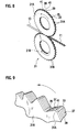
- Fig. 8 is a perspective view showing the arrangement of the corrugation cutter 21 shown in Fig. 7.
- the corrugation cutter 21 including the pair of (first and second) corrugation cutters 21A and 21B, one cutter as a male cutter and the other as a female cutter are placed so as to mesh with each other, and are rotationally driven in the directions of arrows by an unillustrated driving mechanism.
- the structure will be described below primarily by taking the corrugation cutter 21A as an example.
- a plurality of tooth portions 31A are formed radially at a predetermined pitch along the circumferential direction, and apex portions 33 and bottom portions 35 of the tooth portions 31A are alternately formed on the perimeter.
- a plurality of cutting and bending edges 39 are formed on one side surface 37
- a plurality of cutting and bending edges 41 are formed on other side surface 37.
- the bent portions 15 are consecutively formed in the strip thin sheet 13 at a predetermined pitch by the apex portions 33 and the bottom portions 35 of the tooth portions 31A, and the plurality of louvers 18 and 19 such as shown in Fig. 5 are cut and bent out of the flat portions 17 of the strip thin sheet 13 by the cutting and bending edges 39 and 41 formed on the side surfaces 37 of the tooth portions 31A.
- Fig. 10 is an exploded perspective view of the corrugation cutter 21A.
- the corrugation cutter 21A has a structure in which a predetermined number of thin-plate blades 29 each having a plurality of tooth portions 31A formed radially along the circumferential direction are stacked. In each blade 29, cutting and bending edges 39 and 41 are alternately formed at a predetermined pitch along the circumferential direction. It should be noted that the corrugation cutter 21A may be one formed monolithically.
- a plurality of tooth portions 31B are formed radially at a predetermined pitch along the circumferential direction, a plurality of cutting and bending edges are formed on one side surface of each tooth portion 31B, and a plurality of cutting and bending edges are formed on other side surface thereof (reference numerals are not shown).
- the corrugation cutter 21A configured as described above and the corrugation cutter 21B pairing up therewith are placed so that the respective tooth portions 31A and 31B thereof mesh with each other.
- the bent portions 15 and the flat portions 17 are alternately formed in the strip thin sheet 13.
- the cutting and bending edges 39 (41) of one cutter meshing with the cutting and bending edges 41 (39) of the other cutter the louvers 18 and 19 are cut and bent.
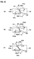
- Fig. 11 is an enlarged side view of the tooth portion 31B (for one blade), and Figs. 12A to 12C are cross-sectional views taken along lines 12A-12A, 12B-12B, and 12C-12C of Fig. 11.
- the edge angles of the cutting and bending edges 39 and 41 are changed so that the angles become smaller in cutting start portions of the louvers 18 and 19 and that the angles become larger in cutting finish portions.
- the louvers 18 and 19 are cut and bent in the order from a heavy lined arrow ab to a heavy lined arrow cd.
- the louvers 18 and 19 are cut and bent in the order from a heavy lined arrow ab to a heavy lined arrow cd.
- let 19a and 19b be cut and bent portions in opposite end portions of the louver 19, and similarly let 18c and 18d be cut and bent portions in opposite end portions of the louver 18.
- the cut and bent portion 19a is the cutting start portion of the louver 19
- the cut and bent portion 19b is the cutting finish portion.
- the cut and bent portion 18c is the cutting start portion of the louver 18, and the cut and bent portion 18d is the cutting finish portion.
- the edge angle of the cutting and bending edge 41 for cutting and bending the louver 19 is gradually increased so that the edge angle becomes an edge angle of ⁇ h in an edge portion 41h for shaping the cut and bent portion 19a, an edge angle of ⁇ hi in an intermediate portion, and an edge angle of ⁇ i in an edge portion 41i for shaping the cut and bent portion 19b.
- these edge angles have the relationship ⁇ i> ⁇ hi> ⁇ h, and the edge angle is steplessly changed between edge angles of ⁇ h and ⁇ i.
- edge angle of the cutting and bending edge 39 for cutting and bending the louver 18 is gradually increased so that the edge angle becomes an edge angle of ⁇ j in an edge portion 39j for shaping the cut and bent portion 18c, an edge angle of ⁇ jk in an intermediate portion, and an edge angle of ⁇ k in an edge portion 39k for shaping the cut and bent portion 18d.
- these edge angles have the relationship ⁇ k> ⁇ jk> ⁇ j, and the edge angle is steplessly changed between edge angles of ⁇ k and ⁇ j .
- cutting surfaces of the edges are formed to face opposite directions on the side surfaces 37 positioned on opposite sides of the apex portion 33 of one tooth portion 31B.
- the corrugation cutter 21A pairing up with the corrugation cutter 21B is also formed in about the same shape.
- the edge angles of the cutting and bending edges are changed so that the angles become smaller in cutting start portions of the louvers 18 and 19 and that the angles become larger in cutting finish portions.
- Fig. 13 is a partial cross-sectional view showing the meshing portion between the corrugation cutters 21A and 21B.
- Each cutting and bending edge of the corrugation cutter 21B is paired with the cutting and bending edge 39 (41) of the corrugation cutter 21A so that the directions and angles of the edges become mirror symmetric when they are meshed with each other.
- the edge angles ⁇ of the cutting and bending edges 39 and 41 determine the bending angles of the louvers 18 and 19. That is, the bending angles become larger in portions in which the edge angles ⁇ are large, and the bending angles become smaller in portions in which the edge angles ⁇ are small.
- cutting and bending are neatly performed in a portion (cutting start portion) cut and bent first. However, in a portion (cutting finish portion) cut and bent later, cutting and bending are not neatly performed. Accordingly, bending angles differ between cut and bent portions at opposite ends of one louver, and distortion occurs in the louver.
- the edge angles of the cutting and bending edges 39 and 41 become smaller in cutting start portions of louvers, and become larger in cutting finish portions. Accordingly, in the cutting start portions neatly cut and bent, shaping is performed so that the bending angles do not become larger; and, in the cutting finish portions not neatly cut and bent, shaping is performed so that the bending angles become larger. Accordingly, as shown in Fig. 5, shaping can be performed so that the bending angles in the cut and bent portions 18c, 18d, 19a, and 19b at both ends of the louvers 18 and 19 become approximately equal.
- edge angles of the cutting and bending edges 39 and 41 optimum values are individually found according to the shape and material of the fin. These values can be determined by performing an experiment or a simulation.
- a method is known in which an inclined edge surface of a cutter is ground at an angle so as to match the grinding surface of a grinding stone (see JPA 1-2833 ) .
- JPA 1-2833 since an inclined edge can be machined only at a constant edge angle, it is technically difficult to manufacture a corrugation cutter (gradual-change corrugation cutter) according to the aforementioned first embodiment in which an edge angle gradually changes.
- a gradual-change corrugation cutter can be machined by machining an inclined edge by means other than a grinding process using a grinding stone, such as a cutting process or a discharge process.
- fin shaping may be adversely affected.
- a discharge process takes more machining time than a grinding process, and therefore causes an increase in cost.
- a corrugation cutter which has functions equivalent to those of the corrugation cutter that can form the louver fin according to the first embodiment and that have edge angles gradually changing, and which can be manufactured by a grinding process.
- Fig. 16 is a perspective view showing the arrangement of the corrugation cutter.
- Fig. 17 is an enlarged partial view of tooth portions.
- Fig. 18 is an exploded perspective view of the corrugation cutter.
- Fig. 19 is a perspective view showing part (corrugated shape for one crest) of a louver fin.
- a corrugation cutter 121 includes a pair of (first and second) corrugation cutters 121A and 121B.
- the corrugation cutters 121A and 121B are placed so that one as a male cutter and the other as a female cutter mesh with each other, and are rotationally driven in the directions of arrows by an unillustrated driving mechanism.
- the following description will be given by taking the corrugation cutter 121A as an example.
- a plurality of tooth portions 131A are formed radially at a predetermined pitch along the circumferential direction, and apex portions 133 and bottom portions 135 of the tooth portions 131A are alternately formed on the perimeter.
- a plurality of cutting and bending edges (shapes of the edges are not shown) 139 are formed on one side surface 137a, and a plurality of cutting and bending edges (shapes of the edges are not shown) 141 are formed on other side surface 137b.
- the corrugation cutter 121A has a structure in which a predetermined number of thin-plate blades 129 each having a plurality of tooth portions 131A formed radially along the circumferential direction are stacked. In each blade 129, cutting and bending edges 139 and 141 are alternately formed at a predetermined pitch along the circumferential direction. It should be noted, however, that the corrugation cutter is not limited to a structure in which a plurality of members are stacked, and may be one formed monolithically.
- a plurality of tooth portions 131B are formed radially at a predetermined pitch along the circumferential direction, a plurality of cutting and bending edges are formed on one side surface of each tooth portion 131B, and a plurality of cutting and bending edges are formed on other side surface thereof (reference numerals are not shown).
- louvers 118 and 119 are cut and bent out of the flat portions 117 of the strip thin sheet 113, thus obtaining a louver fin 111.
- Fig. 14 is an enlarged partial view showing the shapes of side surfaces of adjacent tooth portions 131B.
- Figs. 15A to 15C are cross-sectional views taken along lines 15A-15A, 15B-15B, and 15C-15C of Fig. 14, showing the mesh of cutting and bending edges, and showing a virtual cross section at the time when the corrugation cutters 121A and 121B mesh with each other.
- the cutting and bending edge 139 provided on one side surface 137a of the tooth portion 131B is shaped (ground down) so that an edge height h1 becomes smallest in an apex-side edge portion 139a for machining the cutting start portion of the louver 118, that an edge height h2 becomes largest in a bottom-side edge portion 139a for machining the cutting finish portion of the louver 118, and that the edge height continuously increases from the apex-side edge portion 139a toward the bottom-side edge portion 139b.
- a louver 118 is cut and bent in the direction of an arrow from a cutting start portion 118a toward a cutting finish portion 118b
- a louver 119 is cut and bent in the direction of an arrow from a cutting start portion 119c toward a cutting finish portion 119d (the direction of shaping the fin is assumed to be the direction of an arrow a).
- the edge heights h1 and h2 are represented as heights from a chain line showing the shape of an original gear. It should be noted that a two-dot chain line indicates an edge height before the edge heights h1 and h2 are provided in this embodiment. That is, the two-dot chain line indicates a shape obtained by attaching an edge to the shape of the original gear.
- the cross sections of the cutting and bending edge 139 are the same from the apex-side edge portion 139a to the bottom-side edge portion 139b.
- the thickness t (land width) of the cutting and bending edge 139 in the width direction thereof gradually decreases from the apex-side edge portion 139a toward the bottom-side edge portion 139b.
- an inclined edge 140 is shaped at the same edge angle ⁇ from the apex-side edge portion 139a to the bottom-side edge portion 139b.
- the two-dot chain line shown in Fig. 14 indicates a line for the case where shaping is performed at the edge angle ⁇ from the apex-side edge portion 139a to the bottom-side edge portion 139b.
- the range outside the solid line of the cutting and bending edge 139 indicates a region in which the inclined edge 140 is not actually machined.
- a cutting and bending edge 141 provided on the other side surface 137b of the tooth portion 131B is shaped (ground down) so that the edge height h1 is smallest in a bottom-side edge portion 141a for machining the cutting start portion 119c of the louver 119 shown in Fig. 19, that the edge height h2 is largest in an apex-side edge portion 141b for machining the cutting finish portion 119d of the louver 119, and that the edge height continuously increases from the apex-side edge portion 141a toward the bottom-side edge portion 141b.
- the cross section of the cutting and bending edge 141 is the same from the bottom-side edge portion 141a to the apex-side edge portion 141b.
- the thickness t (land width) of the cutting and bending edge 141 in the width direction thereof gradually decreases from the bottom-side edge portion 141a toward the apex-side edge portion 141b.
- an inclined edge 142 is shaped at the same edge angle ⁇ from the bottom-side edge portion 141a to the apex-side edge portion 141b.
- the two-dot chain line shown in Fig. 14 indicates a line for the case where shaping is performed at the edge angle ⁇ from the bottom-side edge portion 141a to the apex-side edge portion 141b.
- the edge height is continuously cut down from the bottom-side edge portion 141a toward the apex-side edge portion 141b, the range outside the solid line of the cutting and bending edge 141 indicates a region in which the inclined edge 142 is not actually machined.
- the cutting and bending edges 139 provided on the side surfaces 137a of the tooth portions 131B of the corrugation cutter 121B face the cutting and bending edges 139A provided on the side surfaces 137a of the tooth portions 131A of the corrugation cutter 121A
- the cutting and bending edges 141 provided on the side surfaces 137b of the tooth portions 131B of the corrugation cutter 121B face the cutting and bending edges 141A provided on the side surfaces 137b of the tooth portions 131A of the corrugation cutter 121A.
- each cutting and bending edge 139 (141) of the corrugation cutter 121B is paired with the cutting and bending edge 139A (141A) of the corrugation cutter 121A so that the directions and angles of the edges become mirror symmetric when they are meshed with each other.
- Fig. 15A which is a cross section taken along line 15A-15A of Fig. 14
- the flat portion 117 of the strip thin sheet 113 is cut and bent between the bottom-side edge portion 141a of the cutting and bending edge 141 of the corrugation cutter 121B and the apex-side edge portion 141b of the cutting and bending edge 141A of the corrugation cutter 121A.
- the flat portion 117 is cut and bent at a bending angle of ⁇ a along the line connecting a corner portion 142b of the inclined edge (hereinafter referred to as an upper inclined edge) 142 of the corrugation cutter 121A and a corner portion 142a of the inclined edge (hereinafter referred to as a lower inclined edge) 142 of the corrugation cutter 121B.
- Fig. 15B which is a cross section taken along line 15B-15B of Fig. 14
- the flat portion 117 of the strip thin sheet 113 is cut and bent between an intermediate edge portion 141ab of the cutting and bending edge 141 of the corrugation cutter 121B and an intermediate edge portion 141a of the corrugation cutter 121A.
- the flat portion 117 is cut and bent at a bending angle of ⁇ b along the line connecting a corner portion 142ab of the upper inclined edge 142 and a corner portion 142ab of the lower inclined edge 142.
- Fig. 15C which is a cross section taken along line 15C-15C of Fig. 14
- the flat portion 117 of the strip thin sheet 113 is cut and bent between the apex-side edge portion 141b of the cutting and bending edge 141 of the corrugation cutter 121B and the bottom-side edge portion 141a of the cutting and bending edge 141A of the corrugation cutter 121A.
- the flat portion 117 is cut and bent at a bending angle of ⁇ c along the line connecting a corner portion 141a of the upper inclined edge 142 and a corner portion 142b of the lower inclined edge 142.
- the louvers formed in the strip thin sheet 113 are shaped so that the bending angles ⁇ become smaller ( ⁇ a) in cutting start portions and that the bending angles ⁇ become larger ( ⁇ c) in cutting finish portions.
- the edge angles ⁇ of the cutting and bending edges 139 and 141 determine the bending angles of louvers. That is, the bending angles ⁇ become larger when machining is performed using portions in which the edge angles ⁇ are large, and the bending angles ⁇ become smaller when machining is performed using portions in which the edge angles ⁇ are small.
- cutting and bending are neatly performed in a portion (cutting start portion) cut and bent first. However, in a portion (cutting finish portion) cut and bent later, cutting and bending are not neatly performed. Accordingly, bending angles differ between opposite ends of one louver, and distortion occurs in the louver.
- the bending angle ⁇ becomes smaller ( ⁇ a) in the cutting start portion of a louver and becomes larger ( ⁇ c) in the cutting finish portion. Accordingly, as in the case where shaping is performed using a gradual-change corrugation cutter, in the cutting start portion neatly cut and bent originally, shaping is performed so that the bending angle does not become larger; and, in the cutting finish portion not neatly cut and bent, shaping is performed so that the bending angle becomes larger. Accordingly, as shown in Fig.
- the bending angles ⁇ in the cutting start portion 118a and the cutting finish portion 118b of the louver 118 and those in the cutting start portion 119c and the cutting finish portion 119d of the louver 119 can be made approximately equal after shaping.
- the bending angles in opposite end portions of the louvers 118 and 119 shaped in one direction are made approximately equal, there is no distortion in the louvers, and a twist of the entire fin due to distortion can be prevented. Therefore, a warp in the louver fin 111 after shaping can be prevented.
- the corrugation cutters 121A and 121B of this embodiment since the edge angles ⁇ can be made constant, a corrugation cutter can be manufactured which has functions equivalent to those of the gradual-change corrugation cutter according to the aforementioned first embodiment.
- the inclined edges 140 and 142 are machined by not a cutting process but a grinding process, the surface roughness of machined surfaces can be made equivalent to that of current ones, and adverse affects on fin shaping can be avoided. Further, unlike a discharge process, a long machining time is not required. Therefore, an increase in cost can be avoided.
- edge heights and edge angles of the cutting and bending edges 139 and 141 optimum values are individually found according to the shape and material of the fin. These values can be determined by performing an experiment or a simulation.
- a corrugation cutter (gradual-change corrugation cutter) according to the aforementioned first embodiment in which an edge angle gradually changes.
- a gradual-change corrugation cutter can be machined by machining an inclined edge by means other than a grinding process using a grinding stone, such as a cutting process or a discharge process.
- a cutting process is inferior in the surface roughness of a machined surface to a grinding process, fin shaping may be adversely affected.
- a discharge process takes more machining time than a grinding process, and therefore causes an increase in cost.
- a corrugation cutter which has functions equivalent to those of the corrugation cutter according to the aforementioned first embodiment having edge angles gradually changing, and which can be manufactured by a grinding process.
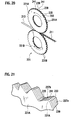
- Fig. 20 is a perspective view showing the arrangement of the corrugation cutter.
- Fig. 21 is an enlarged partial view of tooth portions.
- Fig. 22 is an exploded perspective view of the corrugation cutter.
- Fig. 23 is a perspective view showing part (corrugated shape for one crest) of a louver fin.
- a corrugation cutter 221 includes a pair of (first and second) corrugation cutters 221A and 221B.
- the corrugation cutters 221A and 221B are placed so that one as a male cutter and the other as a female cutter mesh with each other, and are rotationally driven in the directions of arrows by an unillustrated driving mechanism.
- the following description will be given by taking the corrugation cutter 221A as an example.
- a plurality of tooth portions 231A are formed radially at a predetermined pitch along the circumferential direction, and apex portions 233 and bottom portions 235 of the tooth portions 231A are alternately formed on the perimeter.
- a plurality of cutting and bending edges (shapes of the edges are not shown) 239 are formed on one side surface 237a, and a plurality of cutting and bending edges (shapes of the edges are not shown) 241 are formed on other side surface 237b.
- the corrugation cutter 221A has a structure in which a predetermined number of thin-plate blades 229 each having a plurality of tooth portions 231A formed radially along the circumferential direction are stacked. In each blade 229, cutting and bending edges 239 and 241 are alternately formed at a predetermined pitch along the circumferential direction. It should be noted, however, that the corrugation cutter is not limited to a structure in which a plurality of members are stacked, and may be one formed monolithically.
- a plurality of tooth portions 231B are formed radially at a predetermined pitch along the circumferential direction, a plurality of cutting and bending edges are formed on one side surface of each tooth portion 231B, and a plurality of cutting and bending edges are formed on other side surface thereof (reference numerals are not shown).
- louvers 218 and 219 are cut and bent out of the flat portions 217 of the strip thin sheet 213, thus obtaining a louver fin 211.
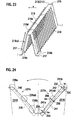
- Fig. 24 is an enlarged partial view showing the shapes of side surfaces of adjacent tooth portions 231B.
- Figs. 25A to 25C are cross-sectional views taken along lines 25A-25A, 25B-25B, and 25C-25C of Fig. 24, showing the mesh of cutting and bending edges, and showing a virtual cross section at the time when the corrugation cutters 221A and 221B mesh with each other.
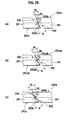
- Fig. 26A shows a state in which cutting and bending edges start cutting the louver 219, and a cross section of the mesh thereof corresponds to Fig. 25A.
- Fig. 26B shows a state in which the cutting and bending edges are cutting an intermediate portion 219cd of the louver 219, and a cross section of the mesh thereof corresponds to Fig. 25B.
- Fig. 26C shows a state in which the cutting and bending edges are cutting a cutting and bending finish portion 219d of the louver 219, and a cross section of the mesh thereof corresponds to Fig. 25C.
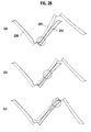
- Figs. 27A to 27C are views showing the states of the flat portion 217 actually cut and bent by the corrugation cutters 221A and 221B at mesh positions corresponding to Figs. 25A to 25C, respectively.
- the cutting and bending edge 239 provided on one side surface 237a of the tooth portion 231B is set so that the thickness (land width) of the edge in the width direction thereof becomes equal between an apex-side edge portion 239a for machining a cutting start portion 218a of the louver 218 shown in Fig. 23 and a bottom-side edge portion 239b for machining the cutting finish portion 218b of the louver 218.
- the thickness (land width) of the edge in the width direction thereof becomes equal between an apex-side edge portion 239a for machining a cutting start portion 218a of the louver 218 shown in Fig. 23 and a bottom-side edge portion 239b for machining the cutting finish portion 218b of the louver 218.
- the cutting and bending edges 239 and 241 are formed so that the angles and land widths of inclined edges are made constant from the apex-side edge portions to the bottom-side edge portions, and the lengths (portions denoted by ha, hb, and hc) vary by which the inclined edges protrude from the portions indicated by chain lines.
- the louver 218 is cut and bent in the direction of an arrow from the cutting start portion 218a toward the cutting finish portion 218b, and the louver 219 is cut and bent in the direction of an arrow from the cutting start portion 219c toward the cutting finish portion 219d (the direction of shaping the fin is assumed to be the direction of an arrow a).
- inclined edges 240 and 242 are formed so that the edge angles of the cutting and bending edges 239 and 241 of the corresponding tooth portions 231A and 231B of the corrugation cutters 221A and 221B are the same angle ⁇ over the longitudinal directions of the edges.
- These inclined edges 240 and 242 are formed by being ground down. Further, the edges denoted by the same reference numeral of the inclined edges 240 and 242 of the cutting and bending edges 239 and 241 are set so as to be parallel to each other with a predetermined clearance c provided therebetween in a state in which they mesh with each other.
- This clearance c is set so that the distance between the inclined edges 240 becomes a large clearance c1 as shown in Fig. 25A at a position (see Fig. 26A) 241a at which the louver 219 starts being cut.
- the flat portion 217 to be cut and bent is cut and bent at a bending angle of ⁇ a along the line connecting a corner portion 242a of the inclined edge (hereinafter referred to as an upper inclined edge) 242 of the corrugation cutter 221A and a corner portion 242a of the inclined edge (hereinafter referred to as a lower inclined edge) 242 of the corrugation cutter 221B.
- Fig. 25B which is a cross-sectional view taken along line 25B-25B at a position 241ab of Fig. 24, an intermediate-level clearance c2 is set.
- the flat portion 217 of the strip thin sheet 213 is cut and bent between an intermediate edge portion 241ab of the cutting and bending edge 241 of the corrugation cutter 221B and an intermediate edge portion 241ab of the corrugation cutter 221A.
- the flat portion 217 is cut and bent at a bending angle of ⁇ b along the line connecting a corner portion 242ab of the upper inclined edge 242 and a corner portion 242ab of the lower inclined edge 242.
- Fig. 25 which is a cross-sectional view taken along line 25C-25C at a position 241b of Fig. 24, a small clearance c3 is set. Further, as shown in Fig. 25C, the flat portion 217 of the strip thin sheet 213 is cut and bent between an end-point-side edge portion 241b of the cutting and bending edge 241 of the corrugation cutter 221B and an edge portion 241a of the corrugation cutter 221A.
- the flat portion 217 is cut and bent at a bending angle of ⁇ c along the line connecting a corner portion 242a of the upper inclined edge 242 and a corner portion 242b of the lower inclined edge 242.
- the clearances cl, c2, and c3 are determined by the protruding quantities (ha, hb, and hc) of the inclined edges.
- Fig. 25A which is a cross section taken along line 25A-25A of Fig. 24
- the flat portion 217 of the strip thin sheet 213 is cut and bent between the bottom-side edge portion 241a of the cutting and bending edge 241 of the corrugation cutter 221B and the edge portion 241b of the corrugation cutter 221A.
- the flat portion 217 of the strip thin sheet 213 is cut and bent at a bending angle of ⁇ a with the clearance c1 along the line connecting the corner portion 242b of the upper inclined edge 242 and the corner portion 242a of the lower inclined edge 242.
- Fig. 25B which is a cross section taken along line 25B-25B of Fig. 24
- the flat portion 217 of the strip thin sheet 213 is cut and bent between the intermediate edge portion 241ab of the cutting and bending edge 241 of the corrugation cutter 221B and the intermediate edge portion 241ab of the corrugation cutter 221A.
- the flat portion 217 is cut and bent at a bending angle of ⁇ b with a clearance of c2 along the line connecting the corner portion 242ab of the upper inclined edge 242 and the corner portion 242ab of the lower inclined edge 242.
- Fig. 25C which is a cross section taken along line 25C-25C of Fig. 24
- the flat portion 217 of the strip thin sheet 213 is cut and bent between the apex-side edge portion 241b of the cutting and bending edge 241 of the corrugation cutter 221B and the edge portion 241a of the corrugation cutter 221A.
- the flat portion 217 is cut and bent at a bending angle of ⁇ c with clearance c3 along the line connecting the corner portion 242a of the upper inclined edge 242 and the corner portion 242b of the lower inclined edge 242.
- the louvers formed in the strip thin sheet 213 are shaped so that the bending angles ⁇ become smaller ( ⁇ a) in cutting start portions and that the bending angles ⁇ become larger ( ⁇ c) in cutting finish portions.
- the edge angles ⁇ of the cutting and bending edges 239 and 241 determine the bending angles of louvers. That is, the bending angles ⁇ become larger when machining is performed using portions in which the edge angles ⁇ are large, and the bending angles ⁇ become smaller when machining is performed using portions in which the edge angles ⁇ are small.
- cutting and bending are neatly performed in a portion (cutting start portion) cut and bent first. However, in a portion (cutting finish portion) cut and bent later, cutting and bending are not neatly performed. Accordingly, bending angles differ between opposite ends of one louver, and distortion occurs in the louver.
- the bending angle ⁇ becomes smaller ( ⁇ a) in the cutting start portion of a louver and becomes larger ( ⁇ c) in the cutting finish portion. Accordingly, as in the case where shaping is performed using a gradual-change corrugation cutter, in the cutting start portion neatly cut and bent performed originally, shaping is performed so that the bending angle does not become larger; and, in the cutting finish portion not neatly cut and bent, shaping is performed so that the bending angle becomes larger. Accordingly, as shown in Fig.
- the bending angles in the cutting start portion 218a and the cutting finish portion 218b of the louver 218 and those in the cutting start portion 219c and the cutting finish portion 219d of the louver 219 can be made approximately equal after shaping.
- the bending angles in opposite end portions of the louvers 218 and 219 shaped in one direction are made approximately equal, there is no distortion in the louvers, and a twist of the entire fin due to distortion can be prevented. Therefore, a warp in the louver fin 211 after shaping can be prevented.
- the edge angles ⁇ can be made constant, a corrugation cutter can be easily manufactured which has functions equivalent to those of the corrugation cutter according to the aforementioned first embodiment.
- the inclined edges 240 and 242 are machined by not a cutting process but a grinding process, the surface roughness of machined surfaces can be made equivalent to that of current ones, and adverse affects on fin shaping can be avoided. Further, unlike a discharge process, a long machining time is not required. Therefore, an increase in cost can be avoided.
- edge heights and edge angles of the cutting and bending edges 239 and 241 optimum values are individually found according to the shape and material of the fin. These values can be determined by performing an experiment or a simulation.
- Corrugation cutters according to the present invention can be applied to heat exchangers including a radiator mounted on a vehicle such as an automobile, and a heater core, a condenser, an evaporator, and the like used in an air conditioner, and are useful particularly in manufacturing a unidirectional louver fin suitable for these heat exchangers.
Landscapes
- Engineering & Computer Science (AREA)
- Mechanical Engineering (AREA)
- Physics & Mathematics (AREA)
- Geometry (AREA)
- Thermal Sciences (AREA)
- General Engineering & Computer Science (AREA)
- Specific Sealing Or Ventilating Devices For Doors And Windows (AREA)
- Punching Or Piercing (AREA)
Abstract
Description
- The present invention relates to a radiating louver fin used in a heat exchanger, and a corrugation cutter for forming this louver fin.
- In cooling devices and air conditioners mounted on vehicles such as automobiles, heat exchangers such as radiators, heater cores, condensers, and evaporators are used. These heat exchangers are configured to exchange with air via a corrugated fin that is formed in a corrugated shape. In recent years, in order to improve heat dissipation performance, a corrugated fin with louvers (hereinafter referred to as a louver fin) has been developed, in which a plurality of louvers that are obliquely open in flat portions (sections between bent portions) of the fin are formed.
- Fig. 1 is a perspective view showing the appearance of a typical louver fin. In a
louver fin 1, a stripthin sheet 3 is formed in a corrugated shape so thatbent portions 3a andflat portions 3b are alternately continued, and that a plurality oflouvers 5 having oblique opening directions are formed in eachflat portion 3b along the width direction. - The
louver fins 1 are classified into bidirectional louver fins and unidirectional louver fins according to the arrangement of thelouvers 5 of theflat portions 3b. The louver arrangement of a bidirectional louver fin is shown in Fig. 2. Fig. 2 is a cross-sectional view of the bidirectional louver fin shown in Fig. 1, when is cut in the width direction. In abidirectional louver fin 1A, the louvers 5 (5a and 5b) formed in oneflat portion 3b are formed to be symmetrical to each other so that the opening directions (bending directions) thereof become opposite on the opposite sides of a central portion C1. Further, the louver arrangement of a unidirectional louver fin is shown in Fig. 3. Fig. 3 is a cross-sectional view of an unillustrated unidirectional louver fin, when is cut in the width direction. In aunidirectional louver fin 1B, all the opening directions of thelouvers 5 are formed to be in the same direction over the entire area of oneflat portion 3b. Thisunidirectional louver fin 1B has advantages such as higher heat dissipation performance and lower air-flow resistance than those of thebidirectional louver fin 1A. - When the
louvers 5 are cut and bent, the material is stretched inward and outward in bottom portions of the louvers, and distortion caused at this time is accumulated around side end portions of thebent portions 3a. In theunidirectional louver fin 1B, the distortion of thelouvers 5 which is caused by cutting and bending is distributed in the same direction over the entire side portions. Accordingly, as shown in Fig. 4, a twist occurs in the entire fin due to the distortion, and this causes the fin to curl. If the fin curls in this way after corrugation forming, it becomes impossible to automate the attachment thereof to a heat exchanger core. - Incidentally, in the
bidirectional louver fin 1A, since distortion caused when the louvers are cut and bent is brought into balance in the central portion C1, the fin does not curl after corrugation forming. - As a conventional technology for preventing such a unidirectional louver fin from curling after corrugation forming, a corrugated fin is known in which peripheral portions of a strip metal sheet are bent to increase rigidity and to prevent the fin from curling after shaping (
JPA 2003-83691 - However, in a corrugated fin described as the conventional technology, the process of bending peripheral portions of a strip metal sheet is needed, and the fin width needs to be increased by a quantity corresponding to the bending. For this reason, there has been the problem that material yields are decreased.
- To solve the above-described problem, it is desired to develop a louver fin having such a shape in which the fin does not curl after corrugation forming, and a corrugation cutter for forming such a louver fin without increasing the number of processes, and without decreasing material yields.
- An object of the present invention is to provide a louver fin which does not curl after corrugation forming, and a corrugation cutter.
-
- [Fig. 1] Fig. 1 is a perspective view showing the appearance of a typical louver fin.
- [Fig. 2] Fig. 2 is a cross-sectional view of a bidirectional louver fin, when is cut in the width direction.
- [Fig. 3] Fig. 3 is a cross-sectional view of a unidirectional louver fin, when is cut in the width direction.
- [Fig. 4] Fig. 4 is a perspective view showing the curling state of a unidirectional louver fin.
- [Fig. 5] Fig. 5 is a perspective view showing part of a louver fin according to a first embodiment of the present invention.
- [Fig. 6] Fig. 6 is a cross-sectional view taken along line 6-6 of Fig. 5.
- [Fig. 7] Fig. 7 is an overall constitution diagram showing a process for manufacturing the louver fin.
- [Fig. 8] Fig. 8 is a perspective view showing the arrangement of a corrugation cutter according to the first embodiment.
- [Fig. 9] Fig. 9 is an enlarged partial view showing a plurality of tooth portions shown in Fig. 8.
- [Fig. 10] Fig. 10 is an exploded perspective view of a corrugation cutter according to the first embodiment of the present invention.
- [Fig. 11] Fig. 11 is an enlarged side view of a tooth portion (for one blade) of the corrugation cutter according to the first embodiment of the present invention.
- [Fig. 12] Figs. 12A to 12C are cross-sectional views taken along
lines 12A-12A, 12B-12B, and 12C-12C of Fig. 11. - [Fig. 13] Fig. 13 is a partial cross-sectional view showing a meshing portion of the corrugation cutter according to the first embodiment of the present invention.
- [Fig. 14] Fig. 14 is an enlarged side view showing a tooth portion (for one blade) of a corrugation cutter according to a second embodiment of the present invention.
- [Fig. 15] Figs. 15A to 15C are cross-sectional views taken along
lines 15A-15A, 15B-15B, and 15C-15C of Fig. 14. - [Fig. 16] Fig. 16 is a perspective view showing the arrangement of the corrugation cutter according to the second embodiment of the present invention.
- [Fig. 17] Fig. 17 is an enlarged partial view showing a plurality of tooth portions shown in Fig. 16.
- [Fig. 18] Fig. 18 is an exploded perspective view of the corrugation cutter according to the second embodiment of the present invention.
- [Fig. 19] Fig. 19 is a perspective view showing part of a louver fin according to the second embodiment of the present invention. [Fig. 20] Fig. 20 is a perspective view showing the arrangement of a corrugation cutter according to a third embodiment of the present invention.
- [Fig. 21] Fig. 21 is an enlarged partial view of a plurality of tooth portions shown in Fig. 20.
- [Fig. 22] Fig. 22 is an exploded perspective view of the corrugation cutter according to the third embodiment of the present invention.
- [Fig. 23] Fig. 23 is a perspective view showing part of a louver fin according to the third embodiment of the present invention. [Fig. 24] Fig. 24 is an enlarged side view of a tooth portion (for one blade) of the corrugation cutter according to the third embodiment of the present invention.
- [Fig. 25] Figs. 25A to 25C are cross-sectional views taken along
lines 25A-25A, 25B-25B, and 25C-25C of Fig. 24. - [Fig. 26] Fig. 26A is an explanatory diagram showing the arrangement of upper and lower cutters, corresponding to Fig. 25A; Fig. 26B is an explanatory diagram showing the arrangement of the upper and lower cutters, corresponding to Fig. 25B; and
- Fig. 26C is an explanatory diagram showing the arrangement of the upper and lower cutters, corresponding to Fig. 25C.
- [Fig. 27] Fig. 27A is an explanatory cross-sectional view showing a state in which the upper and lower cutters are cutting and bending louvers, corresponding to Fig. 25A; Fig. 27B is an explanatory cross-sectional view showing a state in which the upper and lower cutters are cutting and bending the louvers, corresponding to Fig. 25B; and Fig. 27C is an explanatory cross-sectional view showing a state in which the upper and lower cutters are cutting and bending the louvers, corresponding to Fig. 25C.
- Hereinafter, details of louver fins and corrugation cutters according to embodiments of the present invention will be described with reference to drawings.
- Fig. 5 is a perspective view showing part (corrugated shape for one crest) of a louver fin according to a first embodiment, and Fig. 6 is a cross-sectional view taken along line 6-6 of Fig. 5.
- A
louver fin 11 described in this embodiment has a continuous corrugated shape obtained by alternately formingbent portions 15 andflat portions 17 in a stripthin sheet 13 made of, for example, an aluminum member. In eachflat portion 17, a plurality oflouvers thin sheet 13 are arranged parallel to each other along the width direction X of the stripthin sheet 13. - As shown in Fig. 6, these
louvers louvers thin sheet 13. - Here, a process for manufacturing the
louver fin 11 will be briefly described. Fig. 7 is an overall constitution diagram showing the process for manufacturing the louver fin. When the stripthin sheet 13 unwound from aroll 13A passes between a pair ofcorrugation cutters bent portions 15 by corrugation forming and the cutting and bending of thelouvers flat portions 17 by louver forming are performed at almost the same time. Thereafter, a resistance is applied to the feeding of a corrugated portion by pitch adjusting rolls 23A and 23B, thus reducing the length and adjusting the pitch of the adjacentbent portions 15. Then, the stripthin sheet 13 is fed to anext cutting blade 25 to be cut to a predetermined length. Thus, thelouver fin 11 having a length corresponding to the dimensions of a heat exchanger core on which thelouver fin 11 is to be mounted is completed. - Next, the structure of a
corrugation cutter 21 for shaping thelouver fin 11 such as shown in Fig. 5 will be described. - Fig. 8 is a perspective view showing the arrangement of the
corrugation cutter 21 shown in Fig. 7. In thecorrugation cutter 21 including the pair of (first and second)corrugation cutters corrugation cutter 21A as an example. - In the
corrugation cutter 21A, a plurality oftooth portions 31A are formed radially at a predetermined pitch along the circumferential direction, andapex portions 33 andbottom portions 35 of thetooth portions 31A are alternately formed on the perimeter. As shown in an enlarged partial view of Fig. 9, in eachtooth portion 31A, a plurality of cutting and bendingedges 39 are formed on oneside surface 37, and a plurality of cutting and bendingedges 41 are formed onother side surface 37. Thus, thebent portions 15 are consecutively formed in the stripthin sheet 13 at a predetermined pitch by theapex portions 33 and thebottom portions 35 of thetooth portions 31A, and the plurality oflouvers flat portions 17 of the stripthin sheet 13 by the cutting and bendingedges tooth portions 31A. - Fig. 10 is an exploded perspective view of the
corrugation cutter 21A. Thecorrugation cutter 21A has a structure in which a predetermined number of thin-plate blades 29 each having a plurality oftooth portions 31A formed radially along the circumferential direction are stacked. In eachblade 29, cutting and bendingedges corrugation cutter 21A may be one formed monolithically. - Similarly in the corrugation cutter 21B., a plurality of
tooth portions 31B are formed radially at a predetermined pitch along the circumferential direction, a plurality of cutting and bending edges are formed on one side surface of eachtooth portion 31B, and a plurality of cutting and bending edges are formed on other side surface thereof (reference numerals are not shown). - The
corrugation cutter 21A configured as described above and thecorrugation cutter 21B pairing up therewith are placed so that therespective tooth portions apex portions 33 of one of thecorrugation cutters bottom portions 35 of the other cutter, thebent portions 15 and theflat portions 17 are alternately formed in the stripthin sheet 13. At the same time, by the cutting and bending edges 39 (41) of one cutter meshing with the cutting and bending edges 41 (39) of the other cutter, thelouvers - Next, the shapes of the cutting and bending
edges tooth portions 31B will be described. Fig. 11 is an enlarged side view of thetooth portion 31B (for one blade), and Figs. 12A to 12C are cross-sectional views taken alonglines 12A-12A, 12B-12B, and 12C-12C of Fig. 11. - In the
corrugation cutter 21B of this embodiment, the edge angles of the cutting and bendingedges louvers - For example, if the direction of shaping the fin is assumed to be the direction of an arrow Z as shown in Fig. 5, the
louvers louver 19, and similarly let 18c and 18d be cut and bent portions in opposite end portions of thelouver 18. The cut andbent portion 19a is the cutting start portion of thelouver 19, and the cut andbent portion 19b is the cutting finish portion. Moreover, the cut andbent portion 18c is the cutting start portion of thelouver 18, and the cut andbent portion 18d is the cutting finish portion. - On the other hand, in the
corrugation cutter 21B, as shown in Figs. 11 to 12C, the edge angle of the cutting and bendingedge 41 for cutting and bending thelouver 19 is gradually increased so that the edge angle becomes an edge angle of ϕh in anedge portion 41h for shaping the cut andbent portion 19a, an edge angle of ϕhi in an intermediate portion, and an edge angle of ϕi in anedge portion 41i for shaping the cut andbent portion 19b. Here, these edge angles have the relationship ϕi>ϕhi>ϕh, and the edge angle is steplessly changed between edge angles of ϕh and ϕi. - Further, the edge angle of the cutting and bending
edge 39 for cutting and bending thelouver 18 is gradually increased so that the edge angle becomes an edge angle of ϕj in anedge portion 39j for shaping the cut andbent portion 18c, an edge angle of ϕjk in an intermediate portion, and an edge angle of ϕk in anedge portion 39k for shaping the cut andbent portion 18d. Here, these edge angles have the relationship ϕk>ϕjk>ϕj, and the edge angle is steplessly changed between edge angles of ϕk and ϕj . - It should be noted that, with regard to the directions of forming the cutting and bending
edges apex portion 33 of onetooth portion 31B. - On the other hand, the
corrugation cutter 21A pairing up with thecorrugation cutter 21B is also formed in about the same shape. The edge angles of the cutting and bending edges are changed so that the angles become smaller in cutting start portions of thelouvers corrugation cutters corrugation cutter 21B is paired with the cutting and bending edge 39 (41) of thecorrugation cutter 21A so that the directions and angles of the edges become mirror symmetric when they are meshed with each other. - Generally, in louver forming using corrugation cutters, the edge angles ϕ of the cutting and bending
edges louvers - On the other hand, in the
corrugation cutter 21A (21B) of this embodiment, the edge angles of the cutting and bendingedges bent portions louvers louver fin 11 after shaping can be prevented. - Accordingly, in the
corrugation cutter 21 described in this embodiment, there is no need for the process of bending peripheral portions of the stripthin sheet 13 in order to prevent a twist, and there is also no need for increasing the fin width by a quantity corresponding to the bending. Thus, a unidirectional louver fin which does not warp after corrugation forming can be obtained without increasing the number of manufacturing processes and decreasing material utilization. - It should be noted that for the edge angles of the cutting and bending
edges - Next, a corrugation cutter according to a second embodiment of the present invention will be described.
- As a technology relating to the machining of a corrugation cutter such as shown in the aforementioned first embodiment, a method is known in which an inclined edge surface of a cutter is ground at an angle so as to match the grinding surface of a grinding stone (see
JPA 1-2833 JPA 1-2833 - In view of this, in the second embodiment, a corrugation cutter is provided which has functions equivalent to those of the corrugation cutter that can form the louver fin according to the first embodiment and that have edge angles gradually changing, and which can be manufactured by a grinding process.
- First, the basic structure of the corrugation cutter according to the second embodiment will be described using Figs. 16 to 18. Fig. 16 is a perspective view showing the arrangement of the corrugation cutter. Fig. 17 is an enlarged partial view of tooth portions. Fig. 18 is an exploded perspective view of the corrugation cutter. Fig. 19 is a perspective view showing part (corrugated shape for one crest) of a louver fin.
- As shown in Fig. 16, a
corrugation cutter 121 includes a pair of (first and second)corrugation cutters corrugation cutters corrugation cutter 121A as an example. - In the
corrugation cutter 121A, a plurality oftooth portions 131A are formed radially at a predetermined pitch along the circumferential direction, andapex portions 133 andbottom portions 135 of thetooth portions 131A are alternately formed on the perimeter. As shown in Fig. 17, in eachtooth portion 131A, a plurality of cutting and bending edges (shapes of the edges are not shown) 139 are formed on oneside surface 137a, and a plurality of cutting and bending edges (shapes of the edges are not shown) 141 are formed onother side surface 137b. - As shown in Fig. 18, the
corrugation cutter 121A has a structure in which a predetermined number of thin-plate blades 129 each having a plurality oftooth portions 131A formed radially along the circumferential direction are stacked. In eachblade 129, cutting and bendingedges - Similarly, in the
corrugation cutter 121B, a plurality oftooth portions 131B are formed radially at a predetermined pitch along the circumferential direction, a plurality of cutting and bending edges are formed on one side surface of eachtooth portion 131B, and a plurality of cutting and bending edges are formed on other side surface thereof (reference numerals are not shown). - As shown in Fig. 16, when the
corrugation cutter 121A having the above-described cutting and bendingedges corrugation cutter 121B having cutting and bending edges formed therein which have the same structures are meshed with each other and rotationally driven, and a stripthin sheet 113 is supplied between these cutters, theapex portions 133 of one corrugation cutter mesh with thebottom portions 135 of the other corrugation cutter, andbent portions 115 andflat portions 117 are alternately formed in the stripthin sheet 113 such as shown in Fig. 19. At the same time, by the cutting and bending edges 139 (141) of one corrugation cutter meshing with the cutting and bending edges 139 (141) of the other corrugation cutter, a plurality oflouvers flat portions 117 of the stripthin sheet 113, thus obtaining alouver fin 111. - Next, the shapes of the cutting and bending
edges side surfaces tooth portions 131A (131B) will be described. Fig. 14 is an enlarged partial view showing the shapes of side surfaces ofadjacent tooth portions 131B. Figs. 15A to 15C are cross-sectional views taken alonglines 15A-15A, 15B-15B, and 15C-15C of Fig. 14, showing the mesh of cutting and bending edges, and showing a virtual cross section at the time when thecorrugation cutters - In the
corrugation cutter 121B of this embodiment, as shown in Fig. 14, the cutting and bendingedge 139 provided on oneside surface 137a of thetooth portion 131B is shaped (ground down) so that an edge height h1 becomes smallest in an apex-side edge portion 139a for machining the cutting start portion of thelouver 118, that an edge height h2 becomes largest in a bottom-side edge portion 139a for machining the cutting finish portion of thelouver 118, and that the edge height continuously increases from the apex-side edge portion 139a toward the bottom-side edge portion 139b. - Here, as shown in Fig. 19, a
louver 118 is cut and bent in the direction of an arrow from a cuttingstart portion 118a toward a cuttingfinish portion 118b, and alouver 119 is cut and bent in the direction of an arrow from a cuttingstart portion 119c toward a cuttingfinish portion 119d (the direction of shaping the fin is assumed to be the direction of an arrow a). The edge heights h1 and h2 are represented as heights from a chain line showing the shape of an original gear. It should be noted that a two-dot chain line indicates an edge height before the edge heights h1 and h2 are provided in this embodiment. That is, the two-dot chain line indicates a shape obtained by attaching an edge to the shape of the original gear. - Accordingly, the cross sections of the cutting and bending
edge 139 are the same from the apex-side edge portion 139a to the bottom-side edge portion 139b. However, in this embodiment, by continuously cutting down the edge height of the cutting and bendingedge 139 from the position of the two-dot chain line, the thickness t (land width) of the cutting and bendingedge 139 in the width direction thereof gradually decreases from the apex-side edge portion 139a toward the bottom-side edge portion 139b. - Further, an
inclined edge 140 is shaped at the same edge angle θ from the apex-side edge portion 139a to the bottom-side edge portion 139b. The two-dot chain line shown in Fig. 14 indicates a line for the case where shaping is performed at the edge angle θ from the apex-side edge portion 139a to the bottom-side edge portion 139b. In this embodiment, since the edge height is continuously cut down from the apex-side edge portion 139a toward the bottom-side edge portion 139b, the range outside the solid line of the cutting and bendingedge 139 indicates a region in which theinclined edge 140 is not actually machined. - Moreover, a cutting and bending
edge 141 provided on theother side surface 137b of thetooth portion 131B is shaped (ground down) so that the edge height h1 is smallest in a bottom-side edge portion 141a for machining the cuttingstart portion 119c of thelouver 119 shown in Fig. 19, that the edge height h2 is largest in an apex-side edge portion 141b for machining the cuttingfinish portion 119d of thelouver 119, and that the edge height continuously increases from the apex-side edge portion 141a toward the bottom-side edge portion 141b. - Accordingly, the cross section of the cutting and bending
edge 141 is the same from the bottom-side edge portion 141a to the apex-side edge portion 141b. However, in this embodiment, by continuously cutting down the edge height of the cutting and bendingedge 141 from the position of the two-dot chain line, the thickness t (land width) of the cutting and bendingedge 141 in the width direction thereof gradually decreases from the bottom-side edge portion 141a toward the apex-side edge portion 141b. - Further, an
inclined edge 142 is shaped at the same edge angle θ from the bottom-side edge portion 141a to the apex-side edge portion 141b. The two-dot chain line shown in Fig. 14 indicates a line for the case where shaping is performed at the edge angle θ from the bottom-side edge portion 141a to the apex-side edge portion 141b. In this embodiment, since the edge height is continuously cut down from the bottom-side edge portion 141a toward the apex-side edge portion 141b, the range outside the solid line of the cutting and bendingedge 141 indicates a region in which theinclined edge 142 is not actually machined. - In the
tooth portions 131A of thecorrugation cutter 121A pairing up with the above-describedcorrugation cutter 121B, cutting and bending edges (hereinafter denoted by 139A and 141A) similar to those of thetooth portions 131B are formed. Further, when thecorrugation cutters edges 139 provided on the side surfaces 137a of thetooth portions 131B of thecorrugation cutter 121B face the cutting and bending edges 139A provided on the side surfaces 137a of thetooth portions 131A of thecorrugation cutter 121A, and the cutting and bendingedges 141 provided on the side surfaces 137b of thetooth portions 131B of thecorrugation cutter 121B face the cutting and bendingedges 141A provided on the side surfaces 137b of thetooth portions 131A of thecorrugation cutter 121A. Thus, each cutting and bending edge 139 (141) of thecorrugation cutter 121B is paired with the cutting and bending edge 139A (141A) of thecorrugation cutter 121A so that the directions and angles of the edges become mirror symmetric when they are meshed with each other. - Next, the action of the
corrugation cutter 121 according to this embodiment will be described. Here, a description will be given for the case where thelouver 119 is cut and bent in the direction of an arrow from the cuttingstart portion 119c toward the cuttingfinish portion 119d in Fig. 19. - In the machining of the cutting
start portion 119c of thelouver 119, as shown in Fig. 15A which is a cross section taken alongline 15A-15A of Fig. 14, theflat portion 117 of the stripthin sheet 113 is cut and bent between the bottom-side edge portion 141a of the cutting and bendingedge 141 of thecorrugation cutter 121B and the apex-side edge portion 141b of the cutting and bendingedge 141A of thecorrugation cutter 121A. At this time, theflat portion 117 is cut and bent at a bending angle of ϕa along the line connecting acorner portion 142b of the inclined edge (hereinafter referred to as an upper inclined edge) 142 of thecorrugation cutter 121A and acorner portion 142a of the inclined edge (hereinafter referred to as a lower inclined edge) 142 of thecorrugation cutter 121B. - In the machining of an intermediate cut and bent portion 119cd of the
louver 119, as shown in Fig. 15B which is a cross section taken alongline 15B-15B of Fig. 14, theflat portion 117 of the stripthin sheet 113 is cut and bent between an intermediate edge portion 141ab of the cutting and bendingedge 141 of thecorrugation cutter 121B and anintermediate edge portion 141a of thecorrugation cutter 121A. At this time, theflat portion 117 is cut and bent at a bending angle of ϕb along the line connecting a corner portion 142ab of the upperinclined edge 142 and a corner portion 142ab of the lowerinclined edge 142. - In the machining of a cutting
finish portion 119d of thelouver 119, as shown in Fig. 15C which is a cross section taken alongline 15C-15C of Fig. 14, theflat portion 117 of the stripthin sheet 113 is cut and bent between the apex-side edge portion 141b of the cutting and bendingedge 141 of thecorrugation cutter 121B and the bottom-side edge portion 141a of the cutting and bendingedge 141A of thecorrugation cutter 121A. At this time, theflat portion 117 is cut and bent at a bending angle of ϕc along the line connecting acorner portion 141a of the upperinclined edge 142 and acorner portion 142b of the lowerinclined edge 142. - As described above, in the
corrugation cutters edges inclined edges thin sheet 113 are shaped so that the bending angles ϕ become smaller (ϕa) in cutting start portions and that the bending angles ϕ become larger (ϕc) in cutting finish portions. - Generally, in louver forming using corrugation cutters, the edge angles ϕ of the cutting and bending
edges - On the other hand, with the
corrugation cutters 121A (121B) of this embodiment, the bending angle ϕ becomes smaller (ϕa) in the cutting start portion of a louver and becomes larger (ϕc) in the cutting finish portion. Accordingly, as in the case where shaping is performed using a gradual-change corrugation cutter, in the cutting start portion neatly cut and bent originally, shaping is performed so that the bending angle does not become larger; and, in the cutting finish portion not neatly cut and bent, shaping is performed so that the bending angle becomes larger. Accordingly, as shown in Fig. 19, the bending angles ϕ in the cuttingstart portion 118a and the cuttingfinish portion 118b of thelouver 118 and those in the cuttingstart portion 119c and the cuttingfinish portion 119d of thelouver 119 can be made approximately equal after shaping. Thus, since the bending angles in opposite end portions of thelouvers louver fin 111 after shaping can be prevented. - Moreover, in the
corrugation cutters inclined edges - It should be noted that for the edge heights and edge angles of the cutting and bending
edges - Next, a corrugation cutter according to a third embodiment of the present invention will be described.
- In the machining method described in the aforementioned
JPA 1-2833 - In view of this, in the third embodiment, a corrugation cutter is provided which has functions equivalent to those of the corrugation cutter according to the aforementioned first embodiment having edge angles gradually changing, and which can be manufactured by a grinding process.
- First, the basic structure of the corrugation cutter according to the third embodiment will be described using Figs. 20 to 23. Fig. 20 is a perspective view showing the arrangement of the corrugation cutter. Fig. 21 is an enlarged partial view of tooth portions. Fig. 22 is an exploded perspective view of the corrugation cutter. Fig. 23 is a perspective view showing part (corrugated shape for one crest) of a louver fin.
- As shown in Fig. 20, a
corrugation cutter 221 includes a pair of (first and second)corrugation cutters corrugation cutters corrugation cutter 221A as an example. - In the
corrugation cutter 221A, a plurality oftooth portions 231A are formed radially at a predetermined pitch along the circumferential direction, andapex portions 233 andbottom portions 235 of thetooth portions 231A are alternately formed on the perimeter. As shown in Fig. 21, in eachtooth portion 231A, a plurality of cutting and bending edges (shapes of the edges are not shown) 239 are formed on oneside surface 237a, and a plurality of cutting and bending edges (shapes of the edges are not shown) 241 are formed onother side surface 237b. - As shown in Fig. 22, the
corrugation cutter 221A has a structure in which a predetermined number of thin-plate blades 229 each having a plurality oftooth portions 231A formed radially along the circumferential direction are stacked. In eachblade 229, cutting and bendingedges - Similarly, in the
corrugation cutter 221B, a plurality oftooth portions 231B are formed radially at a predetermined pitch along the circumferential direction, a plurality of cutting and bending edges are formed on one side surface of eachtooth portion 231B, and a plurality of cutting and bending edges are formed on other side surface thereof (reference numerals are not shown). - When the
corrugation cutter 221A having the above-described cutting and bendingedges corrugation cutter 221B having cutting and bending edges formed therein which have the same structures are meshed with each other and rotationally driven, and a stripthin sheet 213 is supplied between these cutters as shown in Fig. 20, theapex portions 233 of one corrugation cutter mesh with thebottom portions 235 of the other corrugation cutter, andbent portions 215 andflat portions 217 such as shown in Fig. 23 are alternately formed in the stripthin sheet 213. At the same time, by the cutting and bending edges 239 (241) of one corrugation cutter meshing with the cutting and bending edges 239 (241) of the other corrugation cutter, a plurality oflouvers flat portions 217 of the stripthin sheet 213, thus obtaining alouver fin 211. - Next, the shapes of the cutting and bending
edges side surfaces tooth portion 231A (231B) will be described. Fig. 24 is an enlarged partial view showing the shapes of side surfaces ofadjacent tooth portions 231B. Figs. 25A to 25C are cross-sectional views taken alonglines 25A-25A, 25B-25B, and 25C-25C of Fig. 24, showing the mesh of cutting and bending edges, and showing a virtual cross section at the time when thecorrugation cutters - It should be noted that Fig. 26A shows a state in which cutting and bending edges start cutting the
louver 219, and a cross section of the mesh thereof corresponds to Fig. 25A. Fig. 26B shows a state in which the cutting and bending edges are cutting an intermediate portion 219cd of thelouver 219, and a cross section of the mesh thereof corresponds to Fig. 25B. Fig. 26C shows a state in which the cutting and bending edges are cutting a cutting and bendingfinish portion 219d of thelouver 219, and a cross section of the mesh thereof corresponds to Fig. 25C. Moreover, Figs. 27A to 27C are views showing the states of theflat portion 217 actually cut and bent by thecorrugation cutters - In the
corrugation cutter 221B of this embodiment, as shown in Fig. 24, the cutting and bendingedge 239 provided on oneside surface 237a of thetooth portion 231B is set so that the thickness (land width) of the edge in the width direction thereof becomes equal between an apex-side edge portion 239a for machining a cuttingstart portion 218a of thelouver 218 shown in Fig. 23 and a bottom-side edge portion 239b for machining the cuttingfinish portion 218b of thelouver 218. As shown in Fig. 24, the cutting and bendingedges - Here, as shown in Fig. 23, the
louver 218 is cut and bent in the direction of an arrow from the cuttingstart portion 218a toward the cuttingfinish portion 218b, and thelouver 219 is cut and bent in the direction of an arrow from the cuttingstart portion 219c toward the cuttingfinish portion 219d (the direction of shaping the fin is assumed to be the direction of an arrow a). - In this embodiment, as shown in Figs. 25A to 25C, inclined
edges edges corresponding tooth portions corrugation cutters inclined edges inclined edges edges - Hereinafter, the clearance c will be described with reference to Figs. 24 to 27C.
- This clearance c is set so that the distance between the
inclined edges 240 becomes a large clearance c1 as shown in Fig. 25A at a position (see Fig. 26A) 241a at which thelouver 219 starts being cut. Theflat portion 217 to be cut and bent is cut and bent at a bending angle of ϕa along the line connecting acorner portion 242a of the inclined edge (hereinafter referred to as an upper inclined edge) 242 of thecorrugation cutter 221A and acorner portion 242a of the inclined edge (hereinafter referred to as a lower inclined edge) 242 of thecorrugation cutter 221B. - Next, in the machining of the intermediate cut and bent portion 219cd of the
louver 219, as shown in Fig. 25B which is a cross-sectional view taken alongline 25B-25B at a position 241ab of Fig. 24, an intermediate-level clearance c2 is set. Further, theflat portion 217 of the stripthin sheet 213 is cut and bent between an intermediate edge portion 241ab of the cutting and bendingedge 241 of thecorrugation cutter 221B and an intermediate edge portion 241ab of thecorrugation cutter 221A. At this time, theflat portion 217 is cut and bent at a bending angle of ϕb along the line connecting a corner portion 242ab of the upperinclined edge 242 and a corner portion 242ab of the lowerinclined edge 242. - Next, in the machining of the cutting and bending
end point position 219d of thelouver 219, as shown in Fig. 25 which is a cross-sectional view taken alongline 25C-25C at aposition 241b of Fig. 24, a small clearance c3 is set. Further, as shown in Fig. 25C, theflat portion 217 of the stripthin sheet 213 is cut and bent between an end-point-side edge portion 241b of the cutting and bendingedge 241 of thecorrugation cutter 221B and anedge portion 241a of thecorrugation cutter 221A. At this time, theflat portion 217 is cut and bent at a bending angle of ϕc along the line connecting acorner portion 242a of the upperinclined edge 242 and acorner portion 242b of the lowerinclined edge 242. In this way, in the cutting and bending edges of the corrugation cutter of this embodiment, the clearances cl, c2, and c3 are determined by the protruding quantities (ha, hb, and hc) of the inclined edges. - Next, the action of the
corrugation cutter 221 according to this embodiment will be described. Here, a description will be given for the case where thelouver 219 is cut and bent in the direction of an arrow from the cuttingstart portion 219c toward the cuttingfinish portion 219d in Fig. 23. - In the machining of the cutting
start portion 219c of thelouver 219, as shown in Fig. 25A which is a cross section taken alongline 25A-25A of Fig. 24, theflat portion 217 of the stripthin sheet 213 is cut and bent between the bottom-side edge portion 241a of the cutting and bendingedge 241 of thecorrugation cutter 221B and theedge portion 241b of thecorrugation cutter 221A. At this time, theflat portion 217 of the stripthin sheet 213 is cut and bent at a bending angle of ϕa with the clearance c1 along the line connecting thecorner portion 242b of the upperinclined edge 242 and thecorner portion 242a of the lowerinclined edge 242. - In the machining of the intermediate cut and bent portion 219cd of the
louver 219 shown in Fig. 23, as shown in Fig. 25B which is a cross section taken alongline 25B-25B of Fig. 24, theflat portion 217 of the stripthin sheet 213 is cut and bent between the intermediate edge portion 241ab of the cutting and bendingedge 241 of thecorrugation cutter 221B and the intermediate edge portion 241ab of thecorrugation cutter 221A. At this time, theflat portion 217 is cut and bent at a bending angle of ϕb with a clearance of c2 along the line connecting the corner portion 242ab of the upperinclined edge 242 and the corner portion 242ab of the lowerinclined edge 242. - In the machining of the cutting
finish portion 219d of thelouver 219, as shown in Fig. 25C which is a cross section taken alongline 25C-25C of Fig. 24, theflat portion 217 of the stripthin sheet 213 is cut and bent between the apex-side edge portion 241b of the cutting and bendingedge 241 of thecorrugation cutter 221B and theedge portion 241a of thecorrugation cutter 221A. At this time, theflat portion 217 is cut and bent at a bending angle of ϕc with clearance c3 along the line connecting thecorner portion 242a of the upperinclined edge 242 and thecorner portion 242b of the lowerinclined edge 242. - As described above, in the
corrugation cutters edges inclined edges thin sheet 213 are shaped so that the bending angles ϕ become smaller (ϕa) in cutting start portions and that the bending angles ϕ become larger (ϕc) in cutting finish portions. - Generally, in louver forming using corrugation cutters, the edge angles θ of the cutting and bending
edges - On the other hand, with the
corrugation cutters 221A (221B) of this embodiment, the bending angle ϕ becomes smaller (ϕa) in the cutting start portion of a louver and becomes larger (ϕc) in the cutting finish portion. Accordingly, as in the case where shaping is performed using a gradual-change corrugation cutter, in the cutting start portion neatly cut and bent performed originally, shaping is performed so that the bending angle does not become larger; and, in the cutting finish portion not neatly cut and bent, shaping is performed so that the bending angle becomes larger. Accordingly, as shown in Fig. 23, the bending angles in the cuttingstart portion 218a and the cuttingfinish portion 218b of thelouver 218 and those in the cuttingstart portion 219c and the cuttingfinish portion 219d of thelouver 219 can be made approximately equal after shaping. Thus, since the bending angles in opposite end portions of thelouvers louver fin 211 after shaping can be prevented. - Moreover, in the
corrugation cutters inclined edges - It should be noted that for the edge heights and edge angles of the cutting and bending
edges - Corrugation cutters according to the present invention can be applied to heat exchangers including a radiator mounted on a vehicle such as an automobile, and a heater core, a condenser, an evaporator, and the like used in an air conditioner, and are useful particularly in manufacturing a unidirectional louver fin suitable for these heat exchangers.
Claims (6)
- A louver fin characterized by comprising:a plurality of flat portions which are made of a strip thin sheet, and in each of which a plurality of louvers are cut and bent along a longitudinal direction of the strip thin sheet, are arranged parallel to each other along a width direction of the strip thin sheet, and are formed so that bending angles of the louvers become approximately the same with respect to the longitudinal direction of the strip thin sheet; anda bent portion serving as a boundary between the flat portions and being a portion for coupling the flat portions so that the plurality of flat portions form a corrugated shape.
- A corrugation cutter characterized by comprising: a pair of cutters in each of which a plurality of tooth portions are formed along a circumferential direction, and which are combined to mesh with each other; and
characterized in that:a corrugated fin with louvers is formed by forming alternately bent portions and flat portions in a strip thin sheet, which is supplied between the pair of cutters, at a predetermined pitch by using apex portions and bottom portions of the tooth portions facing each other, and by cutting and bending a plurality of louvers out of the flat portions of the strip thin sheet by using a plurality of cutting and bending edges provided on side surfaces of the tooth portions; and thatan edge angle of the cutting and bending edge provided on a side surface of each of the tooth portions changes along a longitudinal direction of the strip thin sheet so that the angle becomes smaller in a cutting start portion of one of the louvers and that the angle becomes larger in a cutting,finish portion thereof. - A corrugation cutter characterized by comprising:a first cutter in which a plurality of first tooth portions having triangular shapes are formed along a circumferential direction, in which a plurality of first cutting and bending edges for cutting and bending louvers in a strip thin sheet are provided on side surfaces in the circumferential direction of each of the first tooth portions, and in which an edge angle of each of the first cutting and bending edges gradually changes along longitudinal directions of the first cutting and bending edges so that the angle becomes smaller in a cutting start portion of one of the louvers, and that the angle becomes larger in a cutting finish portions thereof; anda second cutter which is rotationally driven in synchronization with the first cutter so as to mesh with the first cutter; in which a plurality of second tooth portions are formed along a circumferential direction; in which the second tooth portions alternately form bent portions and flat portions machine the strip thin sheet into a corrugated shape in conjunction with the first tooth portions by alternately forming bent portions and flat portions of the strip thin sheet; in which a plurality of second cutting and bending edges for cutting and bending the louvers in the strip thin sheet in conjunction with the first tooth portions are provided on the side surfaces in the circumferential direction of the second tooth portions; and in which an edge angle of each of the second cutting and bending edges gradually changes along longitudinal directions of the cutting and bending edges so that the angle becomes smaller in the cutting start portion of one of the louvers, and that the angle becomes larger in the cutting finish portion thereof.
- A corrugation cutter characterized by comprising a pair of cutters in each of which a plurality of tooth portions are radially formed, and which are placed to face each other at a predetermined distance,
characterized in that:a corrugated fin with louvers is formed by forming alternately bent portions and flat portions in a strip thin sheet, which is supplied between the pair of cutters by using apex portions and bottom portions of the tooth portions facing each other, and by cutting and bending a plurality of louvers out of the flat portions of the strip thin sheet by using a plurality of cutting and bending edges provided on side surfaces of the tooth portions;the cutting and bending edge provided on one side surface of each tooth portion is formed with an edge height which continuously increases from the apex-side edge portions toward the bottom-side edge portions, and which becomes smallest in an apex-side edge portion for machining a cutting start portion of one of the louvers, and becomes largest in a bottom-side edge portion for machining a cutting finish portion thereof, the cutting and bending edge including an inclined edge having an edge angle θ formed from the apex-side edge portions to the bottom-side edge portions; and thatthe cutting and bending edge provided on the other side surface of each tooth portion is formed with an edge height which continuously increases from the apex-side edge portions toward the bottom-side edge portions, and which becomes smallest in a bottom-side edge portion for machining the cutting start portion of the louver, and becomes largest in apex-side edge portions for machining the cutting finish portion thereof, and the cutting and bending edge including an inclined edge having an edge angle θ formed from the bottom-side edge portions to the apex-side edge portions. - A corrugation cutter characterized by comprising:a first cutter in which a plurality of first tooth portions are formed along a circumferential direction, in which a plurality of first cutting and bending edges for cutting and bending louvers in a strip thin sheet are provided on side surfaces in the circumferential direction of each of the first tooth portions, and in which an edge height of each of the first cutting and bending edges gradually changes along longitudinal directions of the first cutting and bending edges so that the height becomes smallest in a cutting start portion of one of the louvers, and become largest in a cutting finish portion thereof; anda second cutter which is rotationally driven in synchronization with the first cutter so as to mesh with the first cutter; in which a plurality of second tooth portions are formed along a circumferential direction; in which the second tooth portions machine the strip thin sheet into a corrugated shape in conjunction with the first tooth portions by alternately forming bent portions and flat portions of the strip thin sheet; in which a plurality of second cutting and bending edges for cutting and bending the louvers in the strip thin sheet in conjunction with the first tooth portions are provided on the side surfaces in the circumferential direction of the second tooth portions; and in which an edge height of each of the second cutting and bending edges gradually changes along longitudinal directions of the second cutting and bending edge so that the height becomes smallest in the cutting start portion of the louver, and becomes largest in the cutting finish portion thereof.
- A corrugation cutter characterized by comprising:a first cutter in which a plurality of first tooth portions are formed along a circumferential direction, and in which a plurality of first cutting and bending edges for cutting and bending louvers in a strip thin sheet are provided on side surfaces in the circumferential direction of the first tooth portions, and in which an edge angle θ of each of the first cutting and bending edges is constant along longitudinal directions thereof; anda second cutter which is rotationally driven in synchronization with the first cutter so as to mesh with the first cutter; in which a plurality of second tooth portions are formed along a circumferential direction; in which the second tooth portions machine the strip thin sheet into a corrugated shape in conjunction with the first tooth portions, by alternately forming bent portions and flat portions of the strip thin sheet; in which a plurality of second cutting and bending edges for cutting and bending the louvers in the strip thin sheet in conjunction with the first tooth portions are provided on side surfaces of the second tooth portions in the circumferential direction; in which an edge angle θ of each of the second cutting and bending edges is constant along longitudinal directions thereof; and in which a clearance between the first cutting and bending edge and the second cutting and bending edge gradually changes relatively to be largest in a cutting start portion of one of the louvers and to be smallest in a cutting finish portion thereof.
Applications Claiming Priority (3)
| Application Number | Priority Date | Filing Date | Title |
|---|---|---|---|
| JP2004274877 | 2004-09-22 | ||
| JP2004325485 | 2004-11-09 | ||
| PCT/JP2005/017455 WO2006033382A1 (en) | 2004-09-22 | 2005-09-22 | Louver fin and corrugate cutter |
Publications (2)
| Publication Number | Publication Date |
|---|---|
| EP1795849A1 true EP1795849A1 (en) | 2007-06-13 |
| EP1795849A4 EP1795849A4 (en) | 2007-11-14 |
Family
ID=36090137
Family Applications (1)
| Application Number | Title | Priority Date | Filing Date |
|---|---|---|---|
| EP05785742A Withdrawn EP1795849A4 (en) | 2004-09-22 | 2005-09-22 | Louver fin and corrugate cutter |
Country Status (4)
| Country | Link |
|---|---|
| US (1) | US20080179048A1 (en) |
| EP (1) | EP1795849A4 (en) |
| JP (1) | JPWO2006033382A1 (en) |
| WO (1) | WO2006033382A1 (en) |
Cited By (3)
| Publication number | Priority date | Publication date | Assignee | Title |
|---|---|---|---|---|
| WO2013177942A1 (en) * | 2012-05-15 | 2013-12-05 | Zhao Wenzhi | Air conditioner and automatic control technology |
| CN103537519A (en) * | 2013-11-06 | 2014-01-29 | 株洲南方航鑫机械装备有限责任公司 | Rolling forming die for two-way corrugated fins |
| WO2023163607A1 (en) * | 2022-02-24 | 2023-08-31 | Błażej Kubiak Loscar | A metal rotary heat transfer assembly for a rotary air heat exchanger |
Families Citing this family (8)
| Publication number | Priority date | Publication date | Assignee | Title |
|---|---|---|---|---|
| JP5226463B2 (en) * | 2008-10-27 | 2013-07-03 | 古河スカイ株式会社 | Heat sink with louver and method of assembling the same |
| JP2010118497A (en) * | 2008-11-13 | 2010-05-27 | Furukawa-Sky Aluminum Corp | Heat exchanger equipped with fin with louvers |
| JP5499957B2 (en) * | 2009-07-24 | 2014-05-21 | 株式会社デンソー | Heat exchanger |
| US20110048688A1 (en) * | 2009-09-02 | 2011-03-03 | Delphi Technologies, Inc. | Heat Exchanger Assembly |
| US20110139414A1 (en) * | 2009-12-14 | 2011-06-16 | Delphi Technologies, Inc. | Low Pressure Drop Fin with Selective Micro Surface Enhancement |
| CN103551450B (en) * | 2013-11-06 | 2016-06-15 | 中国南方航空工业(集团)有限公司 | The rolling finned mould of wave |
| JP5716820B1 (en) * | 2013-12-25 | 2015-05-13 | ダイキン工業株式会社 | Fin manufacturing equipment |
| JP6574763B2 (en) * | 2014-05-27 | 2019-09-11 | 株式会社ティラド | Heat exchanger core |
Family Cites Families (13)
| Publication number | Priority date | Publication date | Assignee | Title |
|---|---|---|---|---|
| US2063757A (en) * | 1934-12-29 | 1936-12-08 | Gen Motors Corp | Radiator core |
| US2703700A (en) * | 1950-11-22 | 1955-03-08 | Modine Mfg Co | Heat interchanger |
| US3214954A (en) * | 1963-02-19 | 1965-11-02 | Ford Motor Co | Roll die |
| JPS5022751B1 (en) * | 1970-12-27 | 1975-08-01 | ||
| US4067219A (en) * | 1977-03-23 | 1978-01-10 | Bernard J. Wallis | Heat exchanger fin roll |
| JPS56112015U (en) * | 1980-01-31 | 1981-08-29 | ||
| JPS6074807U (en) * | 1983-10-25 | 1985-05-25 | カルソニックカンセイ株式会社 | Corrugated fin forming roll |
| JPH0716741B2 (en) * | 1990-11-02 | 1995-03-01 | 日本電装株式会社 | Corrugated fin manufacturing equipment |
| US5669438A (en) * | 1996-08-30 | 1997-09-23 | General Motors Corporation | Corrugated cooling fin with louvers |
| US5787972A (en) * | 1997-08-22 | 1998-08-04 | General Motors Corporation | Compression tolerant louvered heat exchanger fin |
| JP3784735B2 (en) * | 2002-03-07 | 2006-06-14 | カルソニックカンセイ株式会社 | Louver fin |
| US6874345B2 (en) * | 2003-01-02 | 2005-04-05 | Outokumpu Livernois Engineering Llc | Serpentine fin with extended louvers for heat exchanger and roll forming tool for manufacturing same |
| US7350387B1 (en) * | 2004-01-23 | 2008-04-01 | Lisk Rodger A | Tooling assembly |
-
2005
- 2005-09-22 US US11/663,448 patent/US20080179048A1/en not_active Abandoned
- 2005-09-22 WO PCT/JP2005/017455 patent/WO2006033382A1/en not_active Ceased
- 2005-09-22 EP EP05785742A patent/EP1795849A4/en not_active Withdrawn
- 2005-09-22 JP JP2006536407A patent/JPWO2006033382A1/en not_active Withdrawn
Non-Patent Citations (2)
| Title |
|---|
| No further relevant documents disclosed * |
| See also references of WO2006033382A1 * |
Cited By (4)
| Publication number | Priority date | Publication date | Assignee | Title |
|---|---|---|---|---|
| WO2013177942A1 (en) * | 2012-05-15 | 2013-12-05 | Zhao Wenzhi | Air conditioner and automatic control technology |
| CN103537519A (en) * | 2013-11-06 | 2014-01-29 | 株洲南方航鑫机械装备有限责任公司 | Rolling forming die for two-way corrugated fins |
| CN103537519B (en) * | 2013-11-06 | 2015-12-09 | 株洲南方航鑫机械装备有限责任公司 | The finned roll forming mould of a kind of two-way wave |
| WO2023163607A1 (en) * | 2022-02-24 | 2023-08-31 | Błażej Kubiak Loscar | A metal rotary heat transfer assembly for a rotary air heat exchanger |
Also Published As
| Publication number | Publication date |
|---|---|
| EP1795849A4 (en) | 2007-11-14 |
| WO2006033382A1 (en) | 2006-03-30 |
| US20080179048A1 (en) | 2008-07-31 |
| JPWO2006033382A1 (en) | 2008-05-15 |
Similar Documents
| Publication | Publication Date | Title |
|---|---|---|
| US6968891B2 (en) | Louver fin and corrugation cutter for forming louver fin | |
| US5636685A (en) | Plate and fin oil cooler with improved efficiency | |
| JP3858324B2 (en) | Inner fin and manufacturing method thereof | |
| JP3814846B2 (en) | Corrugated fin forming roller and corrugated fin forming method | |
| CN101573581B (en) | Heat exchanger fins and manufacturing method thereof | |
| JP2002228379A (en) | Louver fin of heat exchanger, its heat exchanger, and method of assembling the louver fin | |
| US20080179048A1 (en) | Louver Fin and Corrugation Cutter | |
| US6971445B2 (en) | Heat exchanger and method of production | |
| US20050224219A1 (en) | Heat exchanger unit, in particular for a motor vehicle and method for producing said unit | |
| US5509288A (en) | Forming roller for corrugated fin | |
| JP2007278558A (en) | Refrigerant radiator | |
| JP4037241B2 (en) | Corrugated fin | |
| JPH08313183A (en) | Heat exchanger and method for manufacturing corrugated fin for heat exchanger | |
| US8732952B2 (en) | Heat exchanger fin with ribbed hem | |
| US3273227A (en) | Fabrication of heat exchange devices | |
| EP2106520B1 (en) | Heat exchanger fin | |
| JPH01305296A (en) | Corrugate fin for heat exchanger | |
| JP5568330B2 (en) | Heat exchanger | |
| CN111565861A (en) | Tubes for heat exchangers with disturbance devices | |
| JP4196857B2 (en) | Heat exchanger and heat transfer member | |
| JP3816182B2 (en) | Heat exchanger and manufacturing method thereof | |
| JP2014149137A (en) | Flat heat exchange tube and method of manufacturing the same | |
| JP4098547B2 (en) | Heat exchanger fin and heat exchanger fin manufacturing apparatus | |
| CN217210512U (en) | Heat exchanger fin and heat exchanger | |
| JP7788862B2 (en) | Method for manufacturing a heat exchanger and method for manufacturing an air conditioner |
Legal Events
| Date | Code | Title | Description |
|---|---|---|---|
| PUAI | Public reference made under article 153(3) epc to a published international application that has entered the european phase |
Free format text: ORIGINAL CODE: 0009012 |
|
| 17P | Request for examination filed |
Effective date: 20070327 |
|
| AK | Designated contracting states |
Kind code of ref document: A1 Designated state(s): DE FR GB |
|
| A4 | Supplementary search report drawn up and despatched |
Effective date: 20071016 |
|
| DAX | Request for extension of the european patent (deleted) | ||
| RBV | Designated contracting states (corrected) |
Designated state(s): DE FR GB |
|
| 17Q | First examination report despatched |
Effective date: 20080124 |
|
| RTI1 | Title (correction) |
Free format text: CORRUGATE CUTTER |
|
| GRAP | Despatch of communication of intention to grant a patent |
Free format text: ORIGINAL CODE: EPIDOSNIGR1 |
|
| STAA | Information on the status of an ep patent application or granted ep patent |
Free format text: STATUS: THE APPLICATION IS DEEMED TO BE WITHDRAWN |
|
| 18D | Application deemed to be withdrawn |
Effective date: 20110319 |