EP1795731A2 - Abgasrückführung bei einer Brennkraftmaschine - Google Patents
Abgasrückführung bei einer Brennkraftmaschine Download PDFInfo
- Publication number
- EP1795731A2 EP1795731A2 EP06024255A EP06024255A EP1795731A2 EP 1795731 A2 EP1795731 A2 EP 1795731A2 EP 06024255 A EP06024255 A EP 06024255A EP 06024255 A EP06024255 A EP 06024255A EP 1795731 A2 EP1795731 A2 EP 1795731A2
- Authority
- EP
- European Patent Office
- Prior art keywords
- internal combustion
- combustion engine
- line
- cylinder head
- exhaust
- Prior art date
- Legal status (The legal status is an assumption and is not a legal conclusion. Google has not performed a legal analysis and makes no representation as to the accuracy of the status listed.)
- Granted
Links
Images


Classifications
-
- F—MECHANICAL ENGINEERING; LIGHTING; HEATING; WEAPONS; BLASTING
- F02—COMBUSTION ENGINES; HOT-GAS OR COMBUSTION-PRODUCT ENGINE PLANTS
- F02M—SUPPLYING COMBUSTION ENGINES IN GENERAL WITH COMBUSTIBLE MIXTURES OR CONSTITUENTS THEREOF
- F02M26/00—Engine-pertinent apparatus for adding exhaust gases to combustion-air, main fuel or fuel-air mixture, e.g. by exhaust gas recirculation [EGR] systems
- F02M26/13—Arrangement or layout of EGR passages, e.g. in relation to specific engine parts or for incorporation of accessories
- F02M26/17—Arrangement or layout of EGR passages, e.g. in relation to specific engine parts or for incorporation of accessories in relation to the intake system
- F02M26/20—Feeding recirculated exhaust gases directly into the combustion chambers or into the intake runners
-
- F—MECHANICAL ENGINEERING; LIGHTING; HEATING; WEAPONS; BLASTING
- F02—COMBUSTION ENGINES; HOT-GAS OR COMBUSTION-PRODUCT ENGINE PLANTS
- F02M—SUPPLYING COMBUSTION ENGINES IN GENERAL WITH COMBUSTIBLE MIXTURES OR CONSTITUENTS THEREOF
- F02M26/00—Engine-pertinent apparatus for adding exhaust gases to combustion-air, main fuel or fuel-air mixture, e.g. by exhaust gas recirculation [EGR] systems
- F02M26/13—Arrangement or layout of EGR passages, e.g. in relation to specific engine parts or for incorporation of accessories
- F02M26/17—Arrangement or layout of EGR passages, e.g. in relation to specific engine parts or for incorporation of accessories in relation to the intake system
- F02M26/21—Arrangement or layout of EGR passages, e.g. in relation to specific engine parts or for incorporation of accessories in relation to the intake system with EGR valves located at or near the connection to the intake system
-
- F—MECHANICAL ENGINEERING; LIGHTING; HEATING; WEAPONS; BLASTING
- F02—COMBUSTION ENGINES; HOT-GAS OR COMBUSTION-PRODUCT ENGINE PLANTS
- F02M—SUPPLYING COMBUSTION ENGINES IN GENERAL WITH COMBUSTIBLE MIXTURES OR CONSTITUENTS THEREOF
- F02M26/00—Engine-pertinent apparatus for adding exhaust gases to combustion-air, main fuel or fuel-air mixture, e.g. by exhaust gas recirculation [EGR] systems
- F02M26/13—Arrangement or layout of EGR passages, e.g. in relation to specific engine parts or for incorporation of accessories
- F02M26/41—Arrangement or layout of EGR passages, e.g. in relation to specific engine parts or for incorporation of accessories characterised by the arrangement of the recirculation passage in relation to the engine, e.g. to cylinder heads, liners, spark plugs or manifolds; characterised by the arrangement of the recirculation passage in relation to specially adapted combustion chambers
-
- F—MECHANICAL ENGINEERING; LIGHTING; HEATING; WEAPONS; BLASTING
- F02—COMBUSTION ENGINES; HOT-GAS OR COMBUSTION-PRODUCT ENGINE PLANTS
- F02M—SUPPLYING COMBUSTION ENGINES IN GENERAL WITH COMBUSTIBLE MIXTURES OR CONSTITUENTS THEREOF
- F02M26/00—Engine-pertinent apparatus for adding exhaust gases to combustion-air, main fuel or fuel-air mixture, e.g. by exhaust gas recirculation [EGR] systems
- F02M26/13—Arrangement or layout of EGR passages, e.g. in relation to specific engine parts or for incorporation of accessories
- F02M26/42—Arrangement or layout of EGR passages, e.g. in relation to specific engine parts or for incorporation of accessories having two or more EGR passages; EGR systems specially adapted for engines having two or more cylinders
Definitions
- the invention relates to an internal combustion engine with a crankcase and a cylinder head, in each cylinder at least one exhaust duct with a Abgaskanalflansch and a fresh gas duct are admitted with a Frischgaskanalflansch, each of which an exhaust manifold and a fresh gas line are attached, which together form part of an exhaust system and a fresh gas system wherein an exhaust gas recirculation system is provided with a withdrawal line, a control valve having a control valve housing and a feed line, wherein the cylinder head has at least one branching off from the exhaust duct removal channel with a separate from the Abgasschaftflansch Ent Spotifykanalmündung, which opens into a cylinder head wall and is connected to the extraction line , And at least one in the fresh gas channel opening feed channel with a separate from the Frischgaskanalflansch Einspeisekanalmündung, which opens into a cylinder head wall and with the Einspeis e effet is connected.
- Such an internal combustion engine is from the DE 296 23 498 U1 known.
- This internal combustion engine has an exhaust gas recirculation system, which has a removal line and a feed line, which are embedded on opposite cylinder head longitudinal sides in the bearing surface of the cylinder head on the crankcase. Connected to the extraction line and the feed line via a arranged on a cylinder head end transverse channel with the involvement of a control valve.
- the invention has for its object to provide an internal combustion engine with an exhaust gas recirculation system, which can be mounted on the one hand to save space on the engine, on the other hand, the cooling system of the internal combustion engine is not adversely affected.
- This object is achieved in that the exhaust duct and the fresh gas duct open on a common cylinder head longitudinal side and the extraction line and the feed line are arranged one above the other along the cylinder head longitudinal side.
- This design has the advantage that on the one hand, the thermally highly loaded bearing surface between the crankcase and the cylinder head is relieved and on the other hand, the extraction line and the feed line are simple and straightforward and no complicated space-enlarging connection is necessary by the superimposed arrangement. In addition, by removing the extraction line and the feed line from the support surface cooling of the recirculated exhaust gas is possible.
- the extraction line and the feed line are not connected to the exhaust manifold and the fresh gas line, but are directly connected fluidly with recessed in the cylinder head channels, the exhaust manifold and the fresh gas line need not be changed.
- This is particularly advantageous when a variety of differently designed exhaust manifolds and fresh gas lines are offered for a motor series, which, for example, in terms of Distinguish connections for further exhaust pipes or intake pipes or the arrangement of an exhaust gas turbocharger.
- the cylinder head per cylinder has a removal channel mouth and a feed channel mouth.
- a single bleed channel mouth on an exhaust passage in an embodiment of the internal combustion engine as a 4-cylinder engine is taken from the exhaust gas for exhaust gas recirculation, and also provide only to a cylinder feed-in mouth.
- at least each cylinder is advantageously assigned with one intake port mouth and a plurality of (two, three or four) cylinders with an intake port mouth.
- the feed line is made of a cast material, in particular gray cast iron.
- the feed line can be additionally provided with cooling fins and / or wear fastening devices for other components.
- the extraction line is preferably arranged on the crankcase directly under the exhaust manifold.
- the exhaust gas branched off from the exhaust gas ducts is to be supplied to the withdrawal line either flow-optimized or path-optimized.
- the extraction line can also be made in one piece with the crankcase.
- the feed line is integral with the control valve housing manufacturable.
- a bypass bore connects an exhaust passage to the feed line.
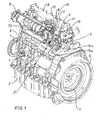
- the internal combustion engine according to FIG. 1 has a crankcase, which is closed on the outside by an oil pan 2 and is covered on the opposite side to the oil pan 2 by a cylinder head 3.
- a crankshaft is mounted, are articulated to the connecting rods, which in turn are connected to pistons which are in cylinders of the crankcase 1 during combustion be moved up and down of the air and fuel in the combustion chambers formed by the pistons, cylinders and the respective cylinder head portion and set the crankshaft in rotation.
- a flywheel 4 is mounted on an engine front side, which is arranged in an SAE housing 5.
- a toothed belt enclosed by a toothed belt housing 6 for driving a camshaft is arranged on the crankshaft, the camshaft having cams for actuating the gas exchange valves in the cylinder head 3 and cams for actuating injection pump elements inserted directly into the crankcase 1 ,
- a pulley 7 is mounted on the crankshaft, which drives a belt, not shown, for example, a blower, a fan or a generator.
- the gas exchange valves used in the cylinder head 3 control the gas exchange with the combustion chambers, wherein the respective gas exchange channels per cylinder are a fresh gas channel 8 and an exhaust duct 9, which open on a cylinder head longitudinal side 21, each with a Frischgaskanalflansch 10 and a Abgaskanalflansch 11.
- the respective gas exchange channels per cylinder are a fresh gas channel 8 and an exhaust duct 9, which open on a cylinder head longitudinal side 21, each with a Frischgaskanalflansch 10 and a Abgaskanalflansch 11.
- the synthetic gas line 12 and the exhaust manifold 13 are specially adapted for different applications of the internal combustion engine and have, for example, variously designed and arranged connections for further exhaust pipes or intake pipes or the use of an exhaust gas turbocharger.
- an exhaust-gas collecting damper can be flanged directly.
- the exhaust gas recirculation system has a branching off from the SAE housing-side exhaust gas channel 9 Extraction channel, which has a withdrawal channel mouth 14a adjacent the Abgaskanalflansch 11. Attached to this removal channel opening 14a is a removal line 15a, which, in order to achieve a desired recooling of the recirculated exhaust gas, has a predetermined length, which is realized by a U-curved course of the removal line 15a.
- the extraction line 15a opens into a control valve housing 16, which is arranged on the SAE housing-side end face of the cylinder head 3.
- control valve housing 16 the control valve is installed, which is electrically, hydraulically or mechanically operated and determines the amount of recirculated exhaust gas continuously or in the form of an "open-close" control.
- the position of a control rod which determines the amount of fuel delivered by the individual injection pump elements, used and evaluated their position to control the control valve. This evaluation can be done for example via the position of the control rod contactless receiving sensors, which then drive an electric adjusting device.
- Such a design has the advantage that the internal combustion engine, if it is designed as a mechanically controlled internal combustion engine, continues to manage without an electronic control device.
- a feed line 17 which is arranged between the fresh gas line 12 and a valve cover hood 18, is guided along the cylinder head 3.
- This feed line 17 is connected to feed channel openings 19, which open separately from the associated Frischgaskanalflansch 10 in the cylinder head wall and are flow-connected via a feed channel to the fresh gas channel 8.
- a removal channel opening 14b is arranged above at least one exhaust gas channel flange 11, to which a short removal line section 20 is fastened in a suitable manner.
- the removal line section 20 opens into a removal line 15b, which extends below the exhaust manifold 13 over at least a partial length of the exhaust manifold 13 parallel to this.
- compensators 22 may be used to compensate for misalignment and thermal stresses.
- the removal line section 20 is in each case arranged between the Frischgaskanalflansch 10 and the Abgaskanalflansch 11 a cylinder unit. In the illustrated embodiment, three Entddlingkanalmünditch 14b are provided, wherein on the belt-side cylinder unit no removal channel mouth 14b is provided.
- the removal of the recirculated exhaust gas in the region above the exhaust gas channel flanges 11 has the advantage that the design of the exhaust gas channels 9 in this area a high back pressure prevails and consequently larger amounts of exhaust gas can be removed.
- FIGS. 1 and 2 It is expressly provided and possible within the scope of the invention to combine the embodiments of FIGS. 1 and 2 with each other.
- a removal channel mouth 14a according to FIG. 1 can additionally be provided and these can be connected to the removal line 15b.
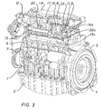
- FIG. 3 Such an embodiment is shown in FIG. 3.
- the SAE-housing-side cylinder 1, a removal channel mouth 14a is arranged, which is connected via a short, shown cutting line section 20a with the extraction line 15c.
- the further cylinders 2 and 3 are - as shown in FIG. 2 - via removal line sections 20th connected to the sampling line 15b.
- the extraction line 15a is formed as a continuous line and the short extraction line section 20a is connected via a sleeve connection with the extraction line 15b. Since the extraction line 15c forms a relatively rigid structural unit with the removal line sections 20, 20a, this line structure must be made precisely fitting for trouble-free installation on the internal combustion engine.
- one or more compensators may be provided at a suitable location in this embodiment.
- the exhaust duct 9 of the cylinder 1 is connected directly via a bypass bore 23 with the feed line 17.
- a small amount of exhaust gas which depends inter alia on the bore diameter of the bypass bore 23, returned.
- This embodiment is based on the following considerations. In order to meet future emission requirements, a high exhaust gas recirculation rate is generally required in the partial load range. In contrast, only a small amount of exhaust gas should be returned in the full load range, so as not to worsen the thermal characteristics of the internal combustion engine and the soot level in this operating condition.
- the adjustment of the necessary exhaust gas recirculation rates is consequently dependent on the power setting of the internal combustion engine.
- low power settings require a high exhaust gas recirculation rate to meet the specific emissions levels.
- the temperature and soot level of the engine is less critical, the exhaust gas recirculation compatibility so higher. This circumstance makes it possible to reduce a small amount of exhaust even at full load.
- the bypass bore 23 may also be in the control valve housing 16 in the mold be introduced that the bypass bore with closed valve disc of the control valve (wherein the valve disc is closed at full load) still releases a certain cross-section.
- the bypass bore 23 has the effect that a higher amount of exhaust gas is recirculated even in the partial load range because the cross section of the bypass bore 23 is available as an additional surface for the recirculation of exhaust gas.
- the previously explained relationships are otherwise shown in the diagram of FIG. 4.
- In the initial state that is to say when there is no bypass bore 23, no exhaust gas is recirculated in the full-load range until the time when the valve disk is opened in the control valve housing 16. This results in approximately a return of exhaust gas according to the dashed curve 1. If the bypass bore is mounted in the control valve housing 16, the result is an exhaust gas recirculation characteristic according to the dash-dotted line curve 2. If the bypass bore 23 is finally mounted in the manner shown in FIG. 3, the curve 3, which, unlike the curve 2, shows that a higher exhaust gas quantity is returned in the partial load range.
- the extraction line 15a, 15b, 15c integrally cast on the crankcase and to integrate the removal channel or the removal line section 20 in the crankcase 1 and the cylinder head 3, in which case the removal channel or the removal line section 20 opens on the crankcase side in the exhaust duct 9.
Landscapes
- Engineering & Computer Science (AREA)
- Chemical & Material Sciences (AREA)
- Combustion & Propulsion (AREA)
- Mechanical Engineering (AREA)
- General Engineering & Computer Science (AREA)
- Exhaust-Gas Circulating Devices (AREA)
- Cylinder Crankcases Of Internal Combustion Engines (AREA)
Abstract
Description
- Die Erfindung betrifft eine Brennkraftmaschine mit einem Kurbelgehäuse und einem Zylinderkopf, in den je Zylinder zumindest ein Abgaskanal mit einem Abgaskanalflansch und ein Frischgaskanal mit einem Frischgaskanalflansch eingelassen sind, an denen jeweils eine Abgassammelleitung und eine Frischgasleitung befestigt sind, die zusammen Teil eines Abgassystems und eines Frischgassystems sind, wobei ein Abgasrückführsystem mit einer Entnahmeleitung, einem ein Steuerventil aufweisenden Steuerventilgehäuse und einer Einspeiseleitung vorgesehen ist, wobei der Zylinderkopf zumindest einen von dem Abgaskanal abzweigenden Entnahmekanal mit einer von dem Abgaskanalflansch separaten Entnahmekanalmündung aufweist, die in eine Zylinderkopfwand mündet und mit der Entnahmeleitung verbunden ist, sowie zumindest einen in den Frischgaskanal einmündenden Einspeisekanal mit einer von dem Frischgaskanalflansch separaten Einspeisekanalmündung, die in eine Zylinderkopfwand mündet und mit der Einspeiseleitung verbunden ist.
- Eine derartige Brennkraftmaschine ist aus der
DE 296 23 498 U1 bekannt. Diese Brennkraftmaschine weist ein Abgasrückführsystem auf, das eine Entnahmeleitung und eine Einspeiseleitung aufweist, die auf gegenüberliegenden Zylinderkopflängsseiten in die Auflagefläche des Zylinderkopfs auf dem Kurbelgehäuse eingelassen sind. Verbunden sind die Entnahmeleitung und die Einspeiseleitung über einen an einer Zylinderkopfstirnseite angeordneten Querkanal unter Einschaltung eines Steuerventils. Dieses Abgasrückführsystem benötigt zwar wenige externe Leitungen, die Entnahmeleitung und die Einspeiseleitung sind aber in thermisch hoch belasteten Bereichen der Brennkraftmaschine angeordnet und belasten somit einerseits die beispielsweise hier angeordnete Zylinderkopfdichtung und verschlechtern andererseits die Wärmeabfuhr in diesem Bereich, da durch diese Leitungen die Kühlmittelfläche genau in dem thermisch hoch belasteten Bereich verringert wird. - Der Erfindung liegt die Aufgabe zugrunde, eine Brennkraftmaschine mit einem Abgasrückführsystem bereitzustellen, das einerseits platzsparend an der Brennkraftmaschine montierbar ist, andererseits aber das Kühlsystem der Brennkraftmaschine nicht nachteilig beeinflusst.
- Diese Aufgabe wird dadurch gelöst, dass der Abgaskanal und der Frischgaskanal auf einer gemeinsamen Zylinderkopflängsseite münden und die Entnahmeleitung und die Einspeiseleitung entlang der Zylinderkopflängsseite übereinanderliegend angeordnet sind. Diese Ausbildung hat den Vorteil, dass einerseits die thermisch hoch belastete Auflagefläche zwischen dem Kurbelgehäuse und dem Zylinderkopf entlastet wird und andererseits die Entnahmeleitung und die Einspeiseleitung einfach und unkompliziert aufgebaut sind und durch die übereinanderliegende Anordnung keine komplizierte bauraumvergrößernde Verbindung notwendig ist. Hinzu kommt, dass durch die Herausnahme der Entnahmeleitung und der Einspeiseleitung aus der Auflagefläche eine Kühlung des zurückgeführten Abgases möglich ist. Dadurch, dass die Entnahmeleitung und die Einspeiseleitung nicht mit der Abgassammelleitung und der Frischgasleitung verbunden sind, sondern direkt mit in den Zylinderkopf eingelassenen Kanälen strömungsverbunden sind, brauchen die Abgassammelleitung und die Frischgasleitung nicht geändert zu werden. Dies ist insbesondere dann vorteilhaft, wenn eine Vielzahl von unterschiedlich ausgebildeten Abgassammelleitungen und Frischgasleitungen für eine Motorenbaureihe angeboten werden, die sich beispielsweise hinsichtlich der Anschlüsse für weiterführende Abgasleitungen oder Ansaugleitungen oder der Anordnung von einem Abgasturbolader unterscheiden.
- In Weiterbildung der Erfindung weist der Zylinderkopf je Zylinder eine Entnahmekanalmündung und eine Einspeisekanalmündung auf. Grundsätzlich ist es im Rahmen der vorliegenden Erfindung möglich, bei einer Ausbildung der Brennkraftmaschine als 4-zylindrige Brennkraftmaschine eine einzige Entnahmekanalmündung an einem Abgaskanal vorzusehen, aus der Abgas für die Abgasrückführung entnommen wird, und auch nur an einen Zylinder eine Einspeisekanalmündung vorzusehen. Um aber eine möglichst unter allen Betriebsbedingungen gleichmäßige Druckverteilung in dem Abgasrückführsystem zu gewährleisten, sind vorteilhaft zumindest jedem Zylinder eine Einspeisekanalmündung und mehreren (zwei, drei oder vier) Zylindern eine Entnahmekanalmündung zugeordnet.
- In weiterer Ausgestaltung der Erfindung ist die Einspeiseleitung aus einem Gusswerkstoff, insbesondere Grauguss, hergestellt. Dabei kann die Einspeiseleitung zusätzlich mit Kühlrippen versehen sein und/oder Befestigungsvorrichtungen für andere Bauteile tragen.
- In Weiterbildung der Erfindung weist die Einspeiseleitung an beiden Stirnseiten einen Flansch zum wahlweisen Anschluss eines separaten Steuerventilgehäuses auf. Durch diese Ausbildung ist es möglich, das Ventilgehäuse je nach Platzangebot bei unterschiedlichen Einbaufällen der Brennkraftmaschine wahlweise anzuordnen.
- In weiterer Ausgestaltung der Erfindung ist die Entnahmeleitung an dem Kurbelgehäuse bevorzugt direkt unter der Abgassammelleitung angeordnet. Dabei ist das aus den Abgaskanälen abgezweigte Abgas entweder strömungs- oder wegoptimiert der Entnahmeleitung zuzuführen. Dabei kann die Entnahmeleitung auch einstückig mit dem Kurbelgehäuse gefertigt werden.
- Im Übrigen ist die Einspeiseleitung einstückig mit dem Steuerventilgehäuse fertigbar.
- In weiterer Ausgestaltung der Erfindung verbindet eine Bypassbohrung einen Abgaskanal mit der Einspeiseleitung. Dadurch wird in allen Betriebszuständen der Brennkraftmaschine, also auch bei Volllast, eine geringe Abgasmenge zurückgeführt.
- Weitere vorteilhafte Ausgestaltungen der Erfindung sind der Zeichnungsbeschreibung zu entnehmen, in der in den Zeichnungen dargestellte Ausführungsbeispiele der Erfindung näher beschrieben sind.
- Es zeigen:
- Fig. 1:
- eine perspektivische Ansicht einer Brennkraftmaschine mit einem Abgasrückführsystem, das aus einem einzigen Entnahmekanal Abgas entnimmt und
- Fig. 2:
- eine Brennkraftmaschine, bei der aus mehreren Entnahmekanälen Abgas zur Rückführung entnommen wird,
- Fig. 3:
- eine Brennkraftmaschine, bei der ebenfalls aus mehreren Entnahmekanälen Abgas zur Rückführung entnommen wird,
- Fig. 4:
- ein Diagramm mit verschiedenen Abgasrückführformen.
- Die Brennkraftmaschine gemäß Fig. 1 weist ein Kurbelgehäuse auf, das bodenseits von einer Ölwanne 2 verschlossen ist und auf der gegenüberliegenden Seite zu der Ölwanne 2 von einem Zylinderkopf 3 abgedeckt ist. In dem Kurbelgehäuse 1 ist eine Kurbelwelle gelagert, an der Pleuel angelenkt sind, die wiederum mit Kolben verbunden sind, die in Zylindern des Kurbelgehäuses 1 bei einer Verbrennung von Luft und Kraftstoff in den von den Kolben, Zylindern und dem jeweiligen Zylinderkopfabschnitt gebildeten Brennräumen auf und ab bewegt werden und die Kurbelwelle in Drehung versetzen. An der Kurbelwelle ist auf einer Brennkraftmaschinenstirnseite ein Schwungrad 4 befestigt, das in einem SAE-Gehäuse 5 angeordnet ist. Auf der gegenüberliegenden Stirnseite zu dem Schwungrad 4 ist an der Kurbelwelle ein von einem Zahnriemengehäuse 6 umschlossener Zahnriemen zum Antrieb einer Nockenwelle angeordnet, wobei die Nockenwelle Nocken zur Betätigung der Gaswechselventile in dem Zylinderkopf 3 und Nocken zur Betätigung von direkt in das Kurbelgehäuse 1 eingesetzten Einspritzpumpenelementen aufweist. Vor dem Zahnriemengehäuse 6 ist auf der Kurbelwelle ein Riemenrad 7 befestigt, das über einen nicht dargestellten Riemen beispielsweise ein Gebläse, ein Lüfterrad oder einen Generator, antreibt.
- Die in dem Zylinderkopf 3 eingesetzten Gaswechselventile steuern den Gaswechsel mit den Brennräumen, wobei die entsprechenden Gaswechselkanäle je Zylinder ein Frischgaskanal 8 und ein Abgaskanal 9 sind, die auf einer Zylinderkopflängsseite 21 mit jeweils einem Frischgaskanalflansch 10 und einem Abgaskanalflansch 11 münden. An den Frischgaskanalflanschen 10 ist eine Frischgasleitung 12 und an den Abgaskanalflanschen 11 ist eine Abgassammelleitung 13 befestigt. Sowohl die Frischgasleitung 12 als auch die Abgassammelleitung 13 sind für unterschiedliche Anwendungen der Brennkraftmaschine speziell angepasst und weisen beispielsweise verschiedenartig ausgebildete und angeordnete Anschlüsse für weiterführende Abgasleitungen oder Ansaugleitungen oder den Einsatz eines Abgasturboladers auf. Ebenso kann als Ausführungsvariante an den Abgaskanalflanschen 11 ein Abgassammeldämpfer direkt angeflanscht werden.
- Das Abgasrückführsystem weist bei dem Ausführungsbeispiel gemäß Fig. 1 einen von dem SAE-gehäuseseitigen Abgaskanal 9 abzweigenden Entnahmekanal auf, der eine Entnahmekanalmündung 14a neben dem Abgaskanalflansch 11 aufweist. An diese Entnahmekanalmündung 14a ist eine Entnahmeleitung 15a befestigt, die zur Erreichung einer gewünschten Rückkühlung des zurückgeführten Abgases eine vorgegebene Länge aufweist, die durch einen U-bogenförmigen Verlauf der Entnahmeleitung 15a realisiert ist. Die Entnahmeleitung 15a mündet in ein Steuerventilgehäuse 16, das auf der SAE-gehäuseseitigen Stirnseite des Zylinderkopfs 3 angeordnet ist. In dem Steuerventilgehäuse 16 ist das Steuerventil eingebaut, das elektrisch, hydraulisch oder mechanisch betätigt wird und die Menge des rückgeführten Abgases stufenlos oder in Form einer "Auf - Zu" -Steuerung festlegt. Dazu wird beispielsweise die Stellung einer Regelstange, die die von den Einzeleinspritzpumpenelementen geförderte Kraftstoffmenge bestimmt, herangezogen und deren Stellung zur Steuerung des Steuerventils ausgewertet. Diese Auswertung kann beispielsweise über die Stellung der Regelstange kontaktlos aufnehmende Sensoren erfolgen, die dann eine elektrische Verstellvorrichtung ansteuern. Eine solche Ausbildung hat den Vorteil, das die Brennkraftmaschine, sofern diese als mechanisch gesteuerte Brennkraftmaschine ausgebildet ist, auch weiterhin ohne eine elektronische Steuereinrichtung auskommt.
- Von dem Steuerventilgehäuse 16 ausgehend ist eine Einspeiseleitung 17, die zwischen der Frischgasleitung 12 und einer Ventildeckelhaube 18 angeordnet ist, entlang des Zylinderkopfs 3 geführt. Diese Einspeiseleitung 17 ist mit Einspeisekanalmündungen 19 verbunden, die separat von dem zugehörigen Frischgaskanalflansch 10 in die Zylinderkopfwand münden und über einen Einspeisekanal mit dem Frischgaskanal 8 strömungsverbunden sind.
- Im Unterschied zu dem Ausführungsbeispiel gemäß Fig. 1 ist bei der Brennkraftmaschine gemäß Fig. 2 die Entnahme des zurückzuführenden Abgases aus den Abgaskanälen 9 konstruktiv anders ausgebildet. Hier ist oberhalb zumindest eines Abgaskanalflansches 11 eine Entnahmekanalmündung 14b angeordnet, an der in geeigneter Weise ein kurzer Entnahmeleitungsabschnitt 20 befestigt ist. Der Entnahmeleitungsabschnitt 20 mündet in eine Entnahmeleitung 15b, die sich unterhalb der Abgassammelleitung 13 über zumindest eine Teillänge der Abgassammelleitung 13 parallel zu dieser erstreckt. In die Entnahmeleitung 15b können Kompensatoren 22 zum Ausgleich von Fluchtungsfehlern und Wärmespannungen eingesetzt sein. Der Entnahmeleitungsabschnitt 20 ist jeweils zwischen dem Frischgaskanalflansch 10 und dem Abgaskanalflansch 11 einer Zylindereinheit angeordnet. Bei dem dargestellten Ausführungsbeispiel sind drei Entnahmekanalmündungen 14b vorgesehen, wobei an der riemenseitigen Zylindereinheit keine Entnahmekanalmündung 14b vorgesehen ist.
- Die Entnahme des zurückzuführenden Abgases im Bereich oberhalb der Abgaskanalflansche 11 hat den Vorteil, dass durch die Ausgestaltung der Abgaskanäle 9 in diesem Bereich ein hoher Staudruck herrscht und demzufolge größere Abgasmengen entnommen werden können.
- Es ist im Rahmen der Erfindung ausdrücklich auch vorgesehen und möglich, die Ausführungsbeispiele der Fig. 1 und 2 miteinander zu kombinieren. Das heißt also konkret bei dem Ausführungsbeispiel gemäß Fig. 2 kann zusätzlich auch eine Entnahmekanalmündung 14a gemäß Fig. 1 vorgesehen sein und diese mit der Entnahmeleitung 15b verbunden sein.
- Eine solche Ausgestaltung ist in der Fig. 3 dargestellt. Bei diesem Ausführungsbeispiel ist dem SAE-gehäuseseitigen Zylinder 1 eine Entnahmekanalmündung 14a angeordnet, die über einen kurzen, geschnitten dargestellten Entnahmeleitungsabschnitt 20a mit der Entnahmeleitung 15c verbunden ist. Die weiteren Zylinder 2 und 3 sind - wie bei der Fig. 2 dargestellt - über Entnahmeleitungsabschnitte 20 mit der Entnahmeleitung 15b verbunden. In diesem Ausführungsbeispiel ist die Entnahmeleitung 15a als durchgehende Leitung ausgebildet und der kurze Entnahmeleitungsabschnitt 20a ist über eine Muffenverbindung mit der Entnahmeleitung 15b verbunden. Da die Entnahmeleitung 15c mit den Entnahmeleitungsabschnitten 20, 20a eine relativ steife Baueinheit bildet, muss dieses Leitungsgebilde passgenau für eine problemlose Montage an der Brennkraftmaschine gefertigt sein. Selbstverständlich können aber bei dieser Ausgestaltung an geeigneter Stelle ein oder mehrere Kompensatoren vorgesehen sein.
- Weiterhin ist bei diesem Ausführungsbeispiel der Abgaskanal 9 des Zylinders 1 direkt über eine Bypassbohrung 23 mit der Einspeiseleitung 17 verbunden. Über diese Bypassbohrung wird in allen Betriebszuständen der Brennkraftmaschine eine geringe Abgasmenge, die unter anderem von dem Bohrungsdurchmesser der Bypassbohrung 23 abhängt, zurückgeführt. Dieser Ausgestaltung liegen die folgenden Überlegungen zugrunde. Um künftige Emissionsanforderungen zu erfüllen, ist im Teillastbereich generell eine hohe Abgasrückführrate notwendig. Dagegen soll im Volllastbereich nur eine geringe Menge Abgas zurückgeführt werden, um die Thermik der Brennkraftmaschine und das Rußniveau in diesem Betriebszustand nicht zu verschlechtern.
- Die Einstellung der notwendigen Abgasrückführraten ist folglich abhängig von der Leistungseinstellung der Brennkraftmaschine. Insbesondere niedrige Nennleistungseinstellungen erfordern eine hohe Abgasrückführrate zur Erfüllung der spezifischen Emissionswerte. Gleichzeitig ist bei geringer Leistungseinstellung im Volllastbereich das Temperatur- und Rußniveau der Brennkraftmaschine weniger kritisch, die Abgasrückführ-Verträglichkeit also höher. Dieser Umstand erlaubt es, auch bei Volllast eine geringe Abgasmenge zurückzuführen. Dies wird durch die Bypassbohrung 23 erreicht. Alternativ kann die Bypassbohrung auch in das Steuerventilgehäuse 16 in der Form eingebracht sein, dass die Bypassbohrung bei geschlossenem Ventilteller des Steuerventils (wobei der Ventilteller bei Volllast geschlossen ist) dennoch einen bestimmten Querschnitt freigibt. Die Bypassbohrung 23 bewirkt, dass auch im Teillastbereich eine höhere Abgasmenge zurückgeführt wird, weil der Querschnitt der Bypassbohrung 23 als zusätzliche Fläche zur Rückführung von Abgas zur Verfügung steht. Die zuvor erläuterten Zusammenhänge sind im Übrigen in dem Diagramm gemäß Fig. 4 dargestellt. Im Ausgangszustand, also bei nicht vorhandener Bypassbohrung 23, wird im Volllastbereich bis zu dem Zeitpunkt des Öffnens des Ventiltellers in dem Steuerventilgehäuse 16 kein Abgas zurückgeführt. Es ergibt sich angenähert eine Rückführung von Abgas gemäß der strichliniierten Kurve ①. Wird die Bypassbohrung in dem Steuerventilgehäuse 16 angebracht, ergibt sich eine Abgasrückführcharakteristik gemäß der strichpunktliniierten Kurve ②. Wird die Bypassbohrung 23 schließlich in der in Fig. 3 dargestellten Weise angebracht, ergibt sich die Kurve ③, die im Unterschied zu der Kurve 2 darstellt, dass im Teillastbereich eine höhere Abgasmenge zurückgeführt wird.
- Weiterhin ist es im Rahmen der Erfindung auch vorgesehen und möglich, insbesondere die Entnahmeleitung 15a, 15b, 15c einstückig an das Kurbelgehäuse anzugießen und den Entnahmekanal beziehungsweise den Entnahmeleitungsabschnitt 20 in das Kurbelgehäuse 1 beziehungsweise den Zylinderkopf 3 zu integrieren, wobei dann der Entnahmekanal beziehungsweise der Entnahmeleitungsabschnitt 20 auf der kurbelgehäuseseitigen Seite in den Abgaskanal 9 einmündet. In einer Abwandlung von dieser Ausführungsform ist es weiterhin vorgesehen, die Entnahmeleitung 15a, 15b, 15c an dem Kurbelgehäuse 1 lösbar zu befestigen und die Entnahmekanäle beziehungsweise die Entnahmeleitungsabschnitte 20 - wie zuvor ausgeführt - in das Kurbelgehäuse 1 beziehungsweise den Zylinderkopf 3 zu integrieren.
- Schließlich ist es auch vorgesehen, die Einspeiseleitung 17 gegebenenfalls zusammen mit dem Steuerventilgehäuse 16 einstückig mit der Ventildeckelhaube 18 zu fertigen.
-
- 1
- Kurbelgehäuse
- 2
- Ölwanne
- 3
- Zylinderkopf
- 4
- Schwungrad
- 5
- SAE-Gehäuse
- 6
- Zahnriemengehäuse
- 7
- Riemenrad
- 8
- Frischgaskanal
- 9
- Abgaskanal
- 10
- Frischgaskanalflansch
- 11
- Abgaskanalflansch
- 12
- Frischgasleitung
- 13
- Abgassammelleitung
- 14a, 14b
- Entnahmekanalmündung
- 15a, 15b, 15c
- Entnahmeleitung
- 16
- Steuerventilgehäuse
- 17
- Einspeiseleitung
- 18
- Ventildeckelhaube
- 19
- Einspeisekanalmündung
- 20, 20a
- Entnahmeleitungsabschnitt
- 21
- Zylinderkopflängsseite
- 22
- Kompensator
- 23
- Bypassbohrung
Claims (10)
- Brennkraftmaschine mit einem Kurbelgehäuse und einem Zylinderkopf, in den je Zylinder zumindest ein Abgaskanal mit einem Abgaskanalflansch und ein Frischgaskanal mit einem Frischgaskanalflansch eingelassen sind, an denen jeweils eine Abgassammelleitung und eine Frischgasleitung befestigt sind, die zusammen Teil eines Abgassystems und eines Frischgassystems sind, wobei ein Abgasrückführsystem mit einer Entnahmeleitung, einem ein Steuerventil aufweisenden Steuerventilgehäuse und einer Einspeiseleitung vorgesehen ist, wobei der Zylinderkopf zumindest einen von dem Abgaskanal abzweigenden Entnahmekanal mit einer von dem Abgaskanalflansch separaten Entnahmekanalmündung aufweist, die in eine Zylinderkopfwand mündet und mit der Entnahmeleitung verbunden ist, sowie zumindest einen in den Frischgaskanal einmündenden Einspeisekanal mit einer von dem Frischgaskanalflansch separaten Einspeisekanalmündung, die in eine Zylinderkopfwand mündet und mit der Einspeiseleitung verbunden ist,
dadurch gekennzeichnet, dass der Abgaskanal (9) und der Frischgaskanal (8) auf einer Zylinderkopflängsseite (21) münden und die Entnahmeleitung (15a, 15b) und die Einspeiseleitung (17) entlang der Zylinderkopflängsseite (21) übereinanderliegend angeordnet sind. - Brennkraftmaschine nach Anspruch 1,
dadurch gekennzeichnet, dass der Zylinderkopf (3) je Zylinder eine Entnahmekanalmündung (14a, 14b) und eine Einspeisekanalmündung (19) aufweist. - Brennkraftmaschine nach Anspruch 1 oder 2,
dadurch gekennzeichnet, dass die Einspeiseleitung (17) aus Gusswerkstoff, insbesondere Grauguss, hergestellt ist. - Brennkraftmaschine nach einem der vorherigen Ansprüche,
dadurch gekennzeichnet, dass die Einspeiseleitung (17) an beiden Stirnseiten einen Flansch zum wahlweisen Anschluss des Steuerventilgehäuses (16) aufweist. - Brennkraftmaschine nach einem der vorherigen Ansprüche,
dadurch gekennzeichnet, dass die Entnahmeleitung (15a, 15b) an dem Kurbelgehäuse (1) befestigt ist. - Brennkraftmaschine nach Anspruch 5,
dadurch gekennzeichnet, dass die Entnahmeleitung (15a, 15b) einstückig mit dem Kurbelgehäuse (1) gefertigt ist. - Brennkraftmaschine nach einem der vorherigen Ansprüche,
dadurch gekennzeichnet, dass die Einspeiseleitung (17) einstückig mit dem Steuerventilgehäuse (16) gefertigt ist. - Brennkraftmaschine nach einem der vorherigen Ansprüche,
dadurch gekennzeichnet, dass die Einspeiseleitung (17) einstückig mit der Ventildeckelhaube (18) gefertigt ist. - Brennkraftmaschine nach einem der vorherigen Ansprüche,
dadurch gekennzeichnet, dass die Einspeiseleitung (17) und das Steuerventilgehäuse (16) einstückig mit der Ventildeckelhaube (18) gefertigt sind. - Brennkraftmaschine nach einem der vorherigen Ansprüche,
dadurch gekennzeichnet, dass eine Bypassbohrung (23) den Abgaskanal (9) mit der Einspeiseleitung (17) verbindet.
Applications Claiming Priority (1)
| Application Number | Priority Date | Filing Date | Title |
|---|---|---|---|
| DE102005059060A DE102005059060A1 (de) | 2005-12-08 | 2005-12-08 | Abgasrückführung bei einer Brennkraftmaschine |
Publications (3)
| Publication Number | Publication Date |
|---|---|
| EP1795731A2 true EP1795731A2 (de) | 2007-06-13 |
| EP1795731A3 EP1795731A3 (de) | 2009-12-09 |
| EP1795731B1 EP1795731B1 (de) | 2016-06-22 |
Family
ID=37603460
Family Applications (1)
| Application Number | Title | Priority Date | Filing Date |
|---|---|---|---|
| EP06024255.9A Not-in-force EP1795731B1 (de) | 2005-12-08 | 2006-11-23 | Abgasrückführung bei einer Brennkraftmaschine |
Country Status (2)
| Country | Link |
|---|---|
| EP (1) | EP1795731B1 (de) |
| DE (1) | DE102005059060A1 (de) |
Family Cites Families (5)
| Publication number | Priority date | Publication date | Assignee | Title |
|---|---|---|---|---|
| JPS555718Y2 (de) * | 1975-02-10 | 1980-02-08 | ||
| GB2292975A (en) * | 1994-09-10 | 1996-03-13 | Ford Motor Co | I.c. engine cylinder head exhaust recirculation |
| DE29623498U1 (de) * | 1996-10-16 | 1998-07-30 | Daimler-Benz Aktiengesellschaft, 70567 Stuttgart | Einrichtung zur Abgasrückführung und Sekundärluftzufuhr für eine Brennkraftmaschine |
| DE10360092A1 (de) * | 2003-12-20 | 2005-07-21 | Deutz Ag | AGR-Kühler für insbesondere luftgekühlte Motoren |
| DE102004023540A1 (de) * | 2004-05-13 | 2005-12-01 | Deutz Ag | Brennkraftmaschine mit Abgasrückführung |
-
2005
- 2005-12-08 DE DE102005059060A patent/DE102005059060A1/de not_active Withdrawn
-
2006
- 2006-11-23 EP EP06024255.9A patent/EP1795731B1/de not_active Not-in-force
Also Published As
| Publication number | Publication date |
|---|---|
| EP1795731A3 (de) | 2009-12-09 |
| EP1795731B1 (de) | 2016-06-22 |
| DE102005059060A1 (de) | 2007-07-05 |
Similar Documents
| Publication | Publication Date | Title |
|---|---|---|
| EP2003320B1 (de) | Zylinderkopf für eine Brennkraftmaschine | |
| DE69915093T2 (de) | Brennkraftmaschine | |
| EP2077388B1 (de) | Kombination mit Zylinderkopf und Zylinderblock und Verwendung einer derartigen Kombination | |
| DE102007053126B4 (de) | Brennkraftmaschine mit gekühlter Abgasrückführung sowie Abgaskrümmer | |
| EP3523524B1 (de) | Brennkraftmaschine | |
| DE102013200255A1 (de) | Brennkraftmaschine mit Frischluftkühlung | |
| DE60111744T2 (de) | Brennkraftmaschine mit abgasrückführung | |
| EP2077387B1 (de) | Verfahren zur Kühlung eines rückzuführenden Abgasstroms einer Brennkraftmaschine | |
| AT512567B1 (de) | Funktionsmodul mit einem Abgasturbolader und einem Abgaskrümmer | |
| DE102017202154A1 (de) | Aufgeladene flüssigkeitsgekühlte Brennkraftmaschine | |
| DE112014000854T5 (de) | Niederdruck-Abgasrezirkulationsmodul | |
| DE202014102859U1 (de) | Kraftfahrzeug-Axialturbine mit Direkteinlass | |
| EP2503125A1 (de) | Mit zwei Abgasturboladern ausgestattete Brennkraftmaschine und Verfahren zum Betreiben einer derartigen Brennkraftmaschine | |
| EP2935827A1 (de) | Saugrohr für einen verbrennungsmotor | |
| DE102013226007A1 (de) | Motor mit einem Wastegate-Ventil und Verfahren zum Betrieb eines Turboladersystems | |
| DE102005025434A1 (de) | Schadstoffbegrenzungseinrichtung für einen Motor | |
| DE102015214107A1 (de) | Verbrennungskraftmaschine mit einem Verdichter und einem zusätzlichen Kompressor | |
| DE102005033163B4 (de) | Verfahren zum Betreiben einer Brennkraftmaschine | |
| DE102004015487A1 (de) | Brennkraftmaschine mit Abgasrückführung | |
| EP1795731B1 (de) | Abgasrückführung bei einer Brennkraftmaschine | |
| EP1957785B1 (de) | Abgasrückführung bei einer luftgekühlten brennkraftmaschine | |
| WO2020191424A1 (de) | Brennkraftmaschine | |
| EP1703115B1 (de) | Thermostatventil mit integriertem AGR-Ventil | |
| EP1825118B1 (de) | Abgasrückführsteuerung mittels lastsignal an einer reiheneinspritzpumpe | |
| DE102013215420A1 (de) | Brennkraftmaschine |
Legal Events
| Date | Code | Title | Description |
|---|---|---|---|
| PUAI | Public reference made under article 153(3) epc to a published international application that has entered the european phase |
Free format text: ORIGINAL CODE: 0009012 |
|
| AK | Designated contracting states |
Kind code of ref document: A2 Designated state(s): AT BE BG CH CY CZ DE DK EE ES FI FR GB GR HU IE IS IT LI LT LU LV MC NL PL PT RO SE SI SK TR |
|
| AX | Request for extension of the european patent |
Extension state: AL BA HR MK YU |
|
| RAP1 | Party data changed (applicant data changed or rights of an application transferred) |
Owner name: DEUTZ AKTIENGESELLSCHAFT |
|
| PUAL | Search report despatched |
Free format text: ORIGINAL CODE: 0009013 |
|
| AK | Designated contracting states |
Kind code of ref document: A3 Designated state(s): AT BE BG CH CY CZ DE DK EE ES FI FR GB GR HU IE IS IT LI LT LU LV MC NL PL PT RO SE SI SK TR |
|
| AX | Request for extension of the european patent |
Extension state: AL BA HR MK RS |
|
| 17P | Request for examination filed |
Effective date: 20100521 |
|
| 17Q | First examination report despatched |
Effective date: 20100630 |
|
| AKX | Designation fees paid |
Designated state(s): AT BE BG CH CY CZ DE DK EE ES FI FR GB GR HU IE IS IT LI LT LU LV MC NL PL PT RO SE SI SK TR |
|
| GRAP | Despatch of communication of intention to grant a patent |
Free format text: ORIGINAL CODE: EPIDOSNIGR1 |
|
| INTG | Intention to grant announced |
Effective date: 20150708 |
|
| GRAP | Despatch of communication of intention to grant a patent |
Free format text: ORIGINAL CODE: EPIDOSNIGR1 |
|
| INTG | Intention to grant announced |
Effective date: 20151006 |
|
| INTG | Intention to grant announced |
Effective date: 20151119 |
|
| GRAS | Grant fee paid |
Free format text: ORIGINAL CODE: EPIDOSNIGR3 |
|
| REG | Reference to a national code |
Ref country code: DE Ref legal event code: R079 Ref document number: 502006015004 Country of ref document: DE Free format text: PREVIOUS MAIN CLASS: F02M0025070000 Ipc: F02M0026000000 |
|
| GRAA | (expected) grant |
Free format text: ORIGINAL CODE: 0009210 |
|
| AK | Designated contracting states |
Kind code of ref document: B1 Designated state(s): AT BE BG CH CY CZ DE DK EE ES FI FR GB GR HU IE IS IT LI LT LU LV MC NL PL PT RO SE SI SK TR |
|
| REG | Reference to a national code |
Ref country code: GB Ref legal event code: FG4D Free format text: NOT ENGLISH |
|
| RIC1 | Information provided on ipc code assigned before grant |
Ipc: F02M 26/00 20160101AFI20160517BHEP |
|
| REG | Reference to a national code |
Ref country code: CH Ref legal event code: EP |
|
| REG | Reference to a national code |
Ref country code: IE Ref legal event code: FG4D Free format text: LANGUAGE OF EP DOCUMENT: GERMAN |
|
| REG | Reference to a national code |
Ref country code: AT Ref legal event code: REF Ref document number: 807812 Country of ref document: AT Kind code of ref document: T Effective date: 20160715 |
|
| REG | Reference to a national code |
Ref country code: DE Ref legal event code: R096 Ref document number: 502006015004 Country of ref document: DE |
|
| REG | Reference to a national code |
Ref country code: LT Ref legal event code: MG4D |
|
| REG | Reference to a national code |
Ref country code: NL Ref legal event code: MP Effective date: 20160622 |
|
| PG25 | Lapsed in a contracting state [announced via postgrant information from national office to epo] |
Ref country code: LT Free format text: LAPSE BECAUSE OF FAILURE TO SUBMIT A TRANSLATION OF THE DESCRIPTION OR TO PAY THE FEE WITHIN THE PRESCRIBED TIME-LIMIT Effective date: 20160622 Ref country code: FI Free format text: LAPSE BECAUSE OF FAILURE TO SUBMIT A TRANSLATION OF THE DESCRIPTION OR TO PAY THE FEE WITHIN THE PRESCRIBED TIME-LIMIT Effective date: 20160622 |
|
| PG25 | Lapsed in a contracting state [announced via postgrant information from national office to epo] |
Ref country code: NL Free format text: LAPSE BECAUSE OF FAILURE TO SUBMIT A TRANSLATION OF THE DESCRIPTION OR TO PAY THE FEE WITHIN THE PRESCRIBED TIME-LIMIT Effective date: 20160622 Ref country code: SE Free format text: LAPSE BECAUSE OF FAILURE TO SUBMIT A TRANSLATION OF THE DESCRIPTION OR TO PAY THE FEE WITHIN THE PRESCRIBED TIME-LIMIT Effective date: 20160622 Ref country code: LV Free format text: LAPSE BECAUSE OF FAILURE TO SUBMIT A TRANSLATION OF THE DESCRIPTION OR TO PAY THE FEE WITHIN THE PRESCRIBED TIME-LIMIT Effective date: 20160622 Ref country code: GR Free format text: LAPSE BECAUSE OF FAILURE TO SUBMIT A TRANSLATION OF THE DESCRIPTION OR TO PAY THE FEE WITHIN THE PRESCRIBED TIME-LIMIT Effective date: 20160923 |
|
| PG25 | Lapsed in a contracting state [announced via postgrant information from national office to epo] |
Ref country code: IT Free format text: LAPSE BECAUSE OF FAILURE TO SUBMIT A TRANSLATION OF THE DESCRIPTION OR TO PAY THE FEE WITHIN THE PRESCRIBED TIME-LIMIT Effective date: 20160622 Ref country code: SK Free format text: LAPSE BECAUSE OF FAILURE TO SUBMIT A TRANSLATION OF THE DESCRIPTION OR TO PAY THE FEE WITHIN THE PRESCRIBED TIME-LIMIT Effective date: 20160622 Ref country code: EE Free format text: LAPSE BECAUSE OF FAILURE TO SUBMIT A TRANSLATION OF THE DESCRIPTION OR TO PAY THE FEE WITHIN THE PRESCRIBED TIME-LIMIT Effective date: 20160622 Ref country code: CZ Free format text: LAPSE BECAUSE OF FAILURE TO SUBMIT A TRANSLATION OF THE DESCRIPTION OR TO PAY THE FEE WITHIN THE PRESCRIBED TIME-LIMIT Effective date: 20160622 Ref country code: IS Free format text: LAPSE BECAUSE OF FAILURE TO SUBMIT A TRANSLATION OF THE DESCRIPTION OR TO PAY THE FEE WITHIN THE PRESCRIBED TIME-LIMIT Effective date: 20161022 Ref country code: RO Free format text: LAPSE BECAUSE OF FAILURE TO SUBMIT A TRANSLATION OF THE DESCRIPTION OR TO PAY THE FEE WITHIN THE PRESCRIBED TIME-LIMIT Effective date: 20160622 |
|
| PG25 | Lapsed in a contracting state [announced via postgrant information from national office to epo] |
Ref country code: PT Free format text: LAPSE BECAUSE OF FAILURE TO SUBMIT A TRANSLATION OF THE DESCRIPTION OR TO PAY THE FEE WITHIN THE PRESCRIBED TIME-LIMIT Effective date: 20161024 Ref country code: ES Free format text: LAPSE BECAUSE OF FAILURE TO SUBMIT A TRANSLATION OF THE DESCRIPTION OR TO PAY THE FEE WITHIN THE PRESCRIBED TIME-LIMIT Effective date: 20160622 Ref country code: PL Free format text: LAPSE BECAUSE OF FAILURE TO SUBMIT A TRANSLATION OF THE DESCRIPTION OR TO PAY THE FEE WITHIN THE PRESCRIBED TIME-LIMIT Effective date: 20160622 Ref country code: BE Free format text: LAPSE BECAUSE OF NON-PAYMENT OF DUE FEES Effective date: 20161130 |
|
| REG | Reference to a national code |
Ref country code: DE Ref legal event code: R097 Ref document number: 502006015004 Country of ref document: DE |
|
| PLBE | No opposition filed within time limit |
Free format text: ORIGINAL CODE: 0009261 |
|
| STAA | Information on the status of an ep patent application or granted ep patent |
Free format text: STATUS: NO OPPOSITION FILED WITHIN TIME LIMIT |
|
| 26N | No opposition filed |
Effective date: 20170323 |
|
| PG25 | Lapsed in a contracting state [announced via postgrant information from national office to epo] |
Ref country code: DK Free format text: LAPSE BECAUSE OF FAILURE TO SUBMIT A TRANSLATION OF THE DESCRIPTION OR TO PAY THE FEE WITHIN THE PRESCRIBED TIME-LIMIT Effective date: 20160622 |
|
| REG | Reference to a national code |
Ref country code: CH Ref legal event code: PL |
|
| GBPC | Gb: european patent ceased through non-payment of renewal fee |
Effective date: 20161123 |
|
| PG25 | Lapsed in a contracting state [announced via postgrant information from national office to epo] |
Ref country code: CH Free format text: LAPSE BECAUSE OF NON-PAYMENT OF DUE FEES Effective date: 20161130 Ref country code: LI Free format text: LAPSE BECAUSE OF NON-PAYMENT OF DUE FEES Effective date: 20161130 |
|
| REG | Reference to a national code |
Ref country code: IE Ref legal event code: MM4A |
|
| REG | Reference to a national code |
Ref country code: FR Ref legal event code: ST Effective date: 20170731 |
|
| PG25 | Lapsed in a contracting state [announced via postgrant information from national office to epo] |
Ref country code: SI Free format text: LAPSE BECAUSE OF FAILURE TO SUBMIT A TRANSLATION OF THE DESCRIPTION OR TO PAY THE FEE WITHIN THE PRESCRIBED TIME-LIMIT Effective date: 20160622 |
|
| PG25 | Lapsed in a contracting state [announced via postgrant information from national office to epo] |
Ref country code: LU Free format text: LAPSE BECAUSE OF NON-PAYMENT OF DUE FEES Effective date: 20161130 |
|
| PG25 | Lapsed in a contracting state [announced via postgrant information from national office to epo] |
Ref country code: FR Free format text: LAPSE BECAUSE OF NON-PAYMENT OF DUE FEES Effective date: 20161130 |
|
| PG25 | Lapsed in a contracting state [announced via postgrant information from national office to epo] |
Ref country code: IE Free format text: LAPSE BECAUSE OF NON-PAYMENT OF DUE FEES Effective date: 20161123 Ref country code: GB Free format text: LAPSE BECAUSE OF NON-PAYMENT OF DUE FEES Effective date: 20161123 |
|
| REG | Reference to a national code |
Ref country code: AT Ref legal event code: MM01 Ref document number: 807812 Country of ref document: AT Kind code of ref document: T Effective date: 20161123 |
|
| PG25 | Lapsed in a contracting state [announced via postgrant information from national office to epo] |
Ref country code: AT Free format text: LAPSE BECAUSE OF NON-PAYMENT OF DUE FEES Effective date: 20161123 |
|
| REG | Reference to a national code |
Ref country code: BE Ref legal event code: MM Effective date: 20161130 |
|
| PG25 | Lapsed in a contracting state [announced via postgrant information from national office to epo] |
Ref country code: CY Free format text: LAPSE BECAUSE OF FAILURE TO SUBMIT A TRANSLATION OF THE DESCRIPTION OR TO PAY THE FEE WITHIN THE PRESCRIBED TIME-LIMIT Effective date: 20160622 Ref country code: HU Free format text: LAPSE BECAUSE OF FAILURE TO SUBMIT A TRANSLATION OF THE DESCRIPTION OR TO PAY THE FEE WITHIN THE PRESCRIBED TIME-LIMIT; INVALID AB INITIO Effective date: 20061123 |
|
| PG25 | Lapsed in a contracting state [announced via postgrant information from national office to epo] |
Ref country code: MC Free format text: LAPSE BECAUSE OF FAILURE TO SUBMIT A TRANSLATION OF THE DESCRIPTION OR TO PAY THE FEE WITHIN THE PRESCRIBED TIME-LIMIT Effective date: 20160622 Ref country code: TR Free format text: LAPSE BECAUSE OF FAILURE TO SUBMIT A TRANSLATION OF THE DESCRIPTION OR TO PAY THE FEE WITHIN THE PRESCRIBED TIME-LIMIT Effective date: 20160622 |
|
| PG25 | Lapsed in a contracting state [announced via postgrant information from national office to epo] |
Ref country code: BG Free format text: LAPSE BECAUSE OF FAILURE TO SUBMIT A TRANSLATION OF THE DESCRIPTION OR TO PAY THE FEE WITHIN THE PRESCRIBED TIME-LIMIT Effective date: 20160622 |
|
| PGFP | Annual fee paid to national office [announced via postgrant information from national office to epo] |
Ref country code: DE Payment date: 20211125 Year of fee payment: 16 |
|
| REG | Reference to a national code |
Ref country code: DE Ref legal event code: R119 Ref document number: 502006015004 Country of ref document: DE |
|
| PG25 | Lapsed in a contracting state [announced via postgrant information from national office to epo] |
Ref country code: DE Free format text: LAPSE BECAUSE OF NON-PAYMENT OF DUE FEES Effective date: 20230601 |