EP1795505A1 - Disk roll - Google Patents
Disk roll Download PDFInfo
- Publication number
- EP1795505A1 EP1795505A1 EP05776095A EP05776095A EP1795505A1 EP 1795505 A1 EP1795505 A1 EP 1795505A1 EP 05776095 A EP05776095 A EP 05776095A EP 05776095 A EP05776095 A EP 05776095A EP 1795505 A1 EP1795505 A1 EP 1795505A1
- Authority
- EP
- European Patent Office
- Prior art keywords
- disks
- disk roll
- disk
- roll
- parts
- Prior art date
- Legal status (The legal status is an assumption and is not a legal conclusion. Google has not performed a legal analysis and makes no representation as to the accuracy of the status listed.)
- Withdrawn
Links
Images

Classifications
-
- C—CHEMISTRY; METALLURGY
- C03—GLASS; MINERAL OR SLAG WOOL
- C03B—MANUFACTURE, SHAPING, OR SUPPLEMENTARY PROCESSES
- C03B35/00—Transporting of glass products during their manufacture, e.g. hot glass lenses, prisms
- C03B35/14—Transporting hot glass sheets or ribbons, e.g. by heat-resistant conveyor belts or bands
- C03B35/16—Transporting hot glass sheets or ribbons, e.g. by heat-resistant conveyor belts or bands by roller conveyors
- C03B35/18—Construction of the conveyor rollers ; Materials, coatings or coverings thereof
- C03B35/181—Materials, coatings, loose coverings or sleeves thereof
-
- B—PERFORMING OPERATIONS; TRANSPORTING
- B65—CONVEYING; PACKING; STORING; HANDLING THIN OR FILAMENTARY MATERIAL
- B65G—TRANSPORT OR STORAGE DEVICES, e.g. CONVEYORS FOR LOADING OR TIPPING, SHOP CONVEYOR SYSTEMS OR PNEUMATIC TUBE CONVEYORS
- B65G39/00—Rollers, e.g. drive rollers, or arrangements thereof incorporated in roller-ways or other types of mechanical conveyors
- B65G39/02—Adaptations of individual rollers and supports therefor
- B65G39/04—Adaptations of individual rollers and supports therefor the rollers comprising a number of roller forming elements mounted on a single axle
-
- C—CHEMISTRY; METALLURGY
- C03—GLASS; MINERAL OR SLAG WOOL
- C03B—MANUFACTURE, SHAPING, OR SUPPLEMENTARY PROCESSES
- C03B35/00—Transporting of glass products during their manufacture, e.g. hot glass lenses, prisms
- C03B35/14—Transporting hot glass sheets or ribbons, e.g. by heat-resistant conveyor belts or bands
- C03B35/16—Transporting hot glass sheets or ribbons, e.g. by heat-resistant conveyor belts or bands by roller conveyors
- C03B35/18—Construction of the conveyor rollers ; Materials, coatings or coverings thereof
- C03B35/185—Construction of the conveyor rollers ; Materials, coatings or coverings thereof having a discontinuous surface for contacting the sheets or ribbons other than cloth or fabric, e.g. having protrusions or depressions, spirally wound cable, projecting discs or tires
-
- C—CHEMISTRY; METALLURGY
- C03—GLASS; MINERAL OR SLAG WOOL
- C03B—MANUFACTURE, SHAPING, OR SUPPLEMENTARY PROCESSES
- C03B35/00—Transporting of glass products during their manufacture, e.g. hot glass lenses, prisms
- C03B35/14—Transporting hot glass sheets or ribbons, e.g. by heat-resistant conveyor belts or bands
- C03B35/16—Transporting hot glass sheets or ribbons, e.g. by heat-resistant conveyor belts or bands by roller conveyors
- C03B35/18—Construction of the conveyor rollers ; Materials, coatings or coverings thereof
- C03B35/189—Disc rollers
-
- F—MECHANICAL ENGINEERING; LIGHTING; HEATING; WEAPONS; BLASTING
- F16—ENGINEERING ELEMENTS AND UNITS; GENERAL MEASURES FOR PRODUCING AND MAINTAINING EFFECTIVE FUNCTIONING OF MACHINES OR INSTALLATIONS; THERMAL INSULATION IN GENERAL
- F16C—SHAFTS; FLEXIBLE SHAFTS; ELEMENTS OR CRANKSHAFT MECHANISMS; ROTARY BODIES OTHER THAN GEARING ELEMENTS; BEARINGS
- F16C13/00—Rolls, drums, discs, or the like; Bearings or mountings therefor
Definitions
- the present invention relates to a disk roll for use in conveying a member in a heated state, such as, e.g., a glass plate discharged from a melting furnace. More particularly, the invention relates to a disk roll for conveyance suitable for use in a step for producing a high-quality glass plate.
- a conveying mechanism is necessary for annealing the glass plate formed from a molten-state glass.
- This conveying mechanism is generally constituted by conveying rolls, and the disk roll is a kind of such conveying roll.
- the glass plate being conveyed is in the state of having a high temperature of about 400-800°C and has low strength.
- the disk rolls are hence required to have some degree of flexibility so as not to damage the glass plate, besides heat resistance and wearing resistance.
- the disk rolls are simultaneously required to have higher strength.
- a disk roll produced by forming doughnut-shape molded plates (disks) having a bulk density of 0.5 g/cm 3 or higher using silica-alumina fibers, an inorganic binder and an organic binder as main ingredients, passing a shaft through plural sheets of the disks to stack them, pressing the stacked disks from both ends to effect sandwich-tightening under compression and thereby form a cylindrical roll, impregnating the surface thereof with an inorganic colloidal solution, and drying the roll (see patent document 1).
- Patent Document 1 Japanese Patent No. 2568845
- the disk roll described above has the following drawback because of its constitution comprising a stack of disks.
- the individual disks shrink in the thickness direction due to the heat conducted from the glass plate in a heated state to form a gap between the disks.
- the so-called falling of powder is apt to occur in which fine fiber pieces, binder particles, etc. shed.
- the glass plates for use in these applications are required to have higher quality and the falling of powder accompanying conveyance is becoming a problem which is not negligible.
- An object of the invention is to provide a disk roll which is remarkably reduced in powder falling as compared with the conventional one and has high thermal shock resistance.
- the invention provides a disk roll for use in conveying a member in a heated state, the disk roll comprising a first disk roll part formed by stacking plural sheets of first disks which are made of a material that tends to shrink upon heating and a second disk roll part formed by stacking plural sheets of second disks which are made of a material that tends to expand upon heating, the outer diameter of the first disks being larger than the outer diameter of the second disks.
- the member being conveyed is supported by the first disk roll part, and the thickness-direction shrinkage of the first disk roll part caused by the heat transferred from the member being conveyed is compensated for by the thickness-direction expansion of the second disk roll part, whereby interlayer separation of the disks can be suppressed.
- the disk roll preferably is one in which the first disks and the second disks each are a molded article comprising inorganic fibers, an inorganic filler, an inorganic binder and an organic binder, and the first disks have a lower density and higher flexibility than the second disks.
- the shocks which the member being conveyed receives during conveyance are mitigated and the member being conveyed is prevented from being damaged.
- the second disk roll part serves to maintain strength, whereby the strength of the whole disk roll can be maintained.
- the first disk roll part should have been impregnated with lithium silicate and colloidal silica
- the second disk roll part should have been impregnated with colloidal silica.
- the first disk roll part can more highly satisfy properties required for the part coming into contact with the member to be conveyed, i.e., strength, non-occurrence of powder falling, and thermal shock resistance.
- the second disk roll part also can be prevented from causing powder falling.
- the second disk roll part does not come into contact with the member being conveyed, and hence, the heat resistance required for the second disk roll part is not so high as for the first disk roll part. Because of this, an impregnant comprising colloidal silica only suffices for the second disk roll part and a cost reduction can be attained.
- a disk roll more reduced in powder falling and having high thermal shock resistance can be provided.
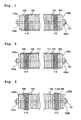
- Fig. 3 is a view showing the completed state of a disk roll.
- This disk roll as a whole is constituted of first disk roll parts each made up of first disks 110 and second disk roll parts each made up of second disks 104.
- the first disks 110 for constituting the first disk roll parts and the second disks 104 for constituting the second disk roll parts are produced.
- the first disks 110 and the second disks 104 each are a molded article comprising inorganic fibers, an inorganic filler, an inorganic binder and an organic binder.
- the compositions of the two kinds of disks are regulated so that the first disks 110 have a lower density and higher flexibility than the second disks.
- the inorganic fibers preferably are ceramic fibers.
- alumina fibers, silica fibers, silica-alumina fibers, or the like can be advantageously used.
- the inorganic filler for example, alumina particles, Kibushi clay, kaolin particles, mica particles, or the like can be advantageously used.
- the inorganic binder for example, a silica sol, alumina sol, or the like can be advantageously used.
- the organic binder for example, an emulsion of an acrylic, etc., an alpha starch paste, or the like can be advantageously used.
- the first disks 110 may be obtained in the following manner.
- An aqueous slurry is prepared which contains given amounts of the inorganic fibers, inorganic filler, inorganic binder and organic binder.
- This aqueous slurry is molded with dehydration and dried to form a platy material having a given thickness.
- a dispersant, fixing agent, coagulant, etc. may be added to the aqueous slurry according to need.
- the amount of the inorganic fibers to be incorporated into the first disks preferably is 40-60% by weight. In case where the amount thereof is smaller than 40% by weight, necessary repulsive (restoring) force is not obtained.
- the amount of the inorganic filler to be incorporated preferably is 40-60% by weight.
- the resultant roll has an increased amount of voids inside and cannot have necessary strength.
- the roll is too rigid and may exert an adverse influence, such as, e.g., giving a scratch on the glass plate as a work.
- first disks 110 disks having a given outer diameter and a given inner diameter are cut out of the platy material to obtain first disks 110.
- density of the first disks 110 varies depending on the member to be conveyed, the appropriate range thereof is, for example, about 0.8-1.7 g/cm 3 when the disks are for use in conveying general glass plates.
- the second disks 104 also may be obtained likewise by forming a platy material from an aqueous slurry having a regulated composition and cutting disks having the same shape as the first disks 110 out of the platy material.
- density of the second disks 104 varies depending on the member to be conveyed, the appropriate range thereof may be about 1.0-1.7 g/cm 3 when the disks are for use in conveying general glass plates like the first disks 110.
- the first disks 110 and second disks 104 thus obtained are introduced to a shaft 101 made of a metal (e.g., iron) as shown in Fig. 1.
- a nut 102a and a flange 103a are fitted beforehand to one end of the shaft 101.
- a given number of second disks 104 are introduced to the shaft 101, and then a given number of first disks 110 are introduced.
- a given number of second disks 104 are introduced to the shaft 101, a given number of first disks 110 are introduced, and then a given number of second disks 104 are further introduced.
- a flange 103b and a nut 102b are fitted.
- the numbers of the first disks 110 and the second disks 104 are appropriately determined according to the overall length of the disk roll, thickness of each disk, kind of the member to be conveyed, etc.
- the nuts 102a and 102b are tightened to press the disks from both sides through the two flanges 103a and 103b and thereby bring the disks into pressure contact with each other.
- the pressure is regulated so that the first disks 110 and the second disks 104 are compressed by about 20% and about 50% (each in thickness), respectively.
- the grinding amount (thickness) is appropriately determined according to the overall length of the disk roll, thickness of each disk, kind of the member to be conveyed, etc.
- the first disks 110 constitute contact parts 110a which come into contact with the member to be conveyed.
- the disk roll be subjected to an impregnation treatment for the purposes of further improving thermal shock resistance and preventing powder falling with higher certainty.
- the first disks 110 which come into contact with the member to be conveyed, are impregnated with a liquid mixture of colloidal silica and lithium silicate in order to impart thermal shock resistance thereto.
- this liquid mixture of colloidal silica and lithium silicate comes to have a molecular structure showing high bonding strength through the formation of alternate linkage of silicon atoms and oxygen atoms as shown below. As a result, high thermal shock resistance is obtained.
- the proportions of the colloidal silica and lithium silicate in the liquid mixture thereof is preferably such that the ratio of (colloidal silica):(lithium silicate) is from 90:10 to 99:1, from the standpoints of the improvement of thermal shock resistance and the degree of shrinkage.
- the amount of the liquid mixture of colloidal silica and lithium silicate with which the first disks 110 are to be impregnated is important in designing roll flexibility. Small impregnation amounts result in a flexible roll, while large impregnation amounts result in a rigid roll. In the invention, a suitable impregnation amount is 5-60% in terms of proportion by volume.
- the disks are dried, for example, at 80°C for about 12 hours to complete the impregnation treatment.
- the first disks 110 obtained through this impregnation treatment contain a colloidal silica ingredient and a lithium silicate ingredient, and the concentrations of these ingredients increase toward the disk surface. Thus, high thermal shock resistance is imparted to the first disks 110.
- the second disks 104 need not have thermal shock resistance as high as that of the first disks 110 because they do not come into contact with the member being conveyed. Consequently, the second disks 104 are impregnated with colloidal silica in an amount of 0.5-20% in terms of proportion by volume. Thus, the cost of impregnants can be reduced.
- the second disks 104 do not contain lithium silicate, the thermal shrinkage described above is inhibited and the disks in a pressure contact state show an intense repulsive force. This brings about an advantage that the thickness-direction shrinkage of the first disks 110 is compensated for by the repulsive force of the second disks 104 to thereby make the first disks 110 less apt to cause interlayer separation between these.
- the disk roll of the invention thus obtained is thermally stable and is significantly reduced in powder falling.
- the first disk roll parts which comprise first disks 110 having moderate flexibility, can be always in soft contact with a glass to prevent the glass from being damaged and enable the member being conveyed to be satisfactorily conveyed while causing no vibrations, etc.
- the second disk roll parts which comprise second disks 104, suppress the occurrence of interlayer separation of the disks due to the thermal shrinkage in the first disk roll parts. Thus, stable conveyance is maintained over a long period of time.
- first disks having an outer diameter of 200 mm, inner diameter, i.e., hole diameter, of 100 mm, and thickness of 15 mm were punched out of the platy molded article with a press.
- the first disks obtained had a density of 0.6 g/cm 3 . Although these disks were more flexible than the second disks described below, they were inferior in strength.
- Silica-alumina fibers fiber diameter, 3 ⁇ m
- Alumina particles particle diameter, 0.5-3.0 ⁇ m
- Inorganic binder sica sol: dry solid ingredient
- Organic binder acrylic emulsion
- Inorganic fixing agent 5% aqueous solution
- Polymeric coagulant 0.05% aqueous solution
- the raw materials and water shown below were mixed together to prepare an aqueous slurry.
- This slurry was molded with dehydration and dried to obtain a platy molded article having a thickness of 15 mm.
- second disks having an outer diameter of 200 mm, inner diameter, i.e., hole diameter, of 100 mm, and thickness of 15 mm were punched out of the platy molded article with a press.
- the second disks obtained had a density of 1.0 g/cm 3 , and had a higher strength than the first disks.
- a nut 102a and a flange 103a were fitted to a shaft 101 made of iron, and second disks 104 to make a thickness of 10 cm, first disks 110 to make a thickness of 20 cm, second disks 104 to make a thickness of 150 cm, first disks 110 to make a thickness 20 cm, and second disks 104 to make a thickness of 10 cm were introduced to the shaft 101 in this order.
- a flange 103b and a nut 102b were then fitted thereto. Thereafter, the nuts 102a and 102b were tightened through the flanges 103a and 103b to bring the disks into press contact with each other.
- the first disks 110 and the second disks 104 came to have densities of 0.8 g/cm 3 and 1.4 g/cm 3 , respectively.
- the second disks 104 were ground to remove a surface layer thereof having a thickness of 4 mm to form a disk roll such as that shown in Fig. 3.
- the disk roll obtained was mounted in an actual glass plate conveying mechanism and this conveying mechanism was practically used to convey a glass plate sent from a melting furnace. As a result, the glass surface suffered no scratches and, even after the lapse of 1,000 hours, no powder falling was observed. The conveyance was stably conducted.
- a disk roll having the shape shown in Fig. 4 was produced using the same first disks 110 and second disks 104 as those shown above, and the elastic deformation of the first disks 110 was measured.
- the measurement was made in the following manner. As shown in the figure, a supporting rod 20 was inserted into a shaft 101, and the supporting rod 20 was fixed on a pair of supporting tables 30 placed on the left and right sides. A compressive load F of 9 kgf/cm was imposed on one of the first disks 110 through an indentator 10 and the amount of the resultant deformation was determined. As a result, the first disk 110 showed such flexibility that it had an elastic deformation of 0.05 mm under a load of 9 kgf/cm.
- colloidal silica:lithium silicate 95:5
- the disk roll obtained was mounted in an actual glass plate conveying mechanism and this conveying mechanism was practically used to convey a glass plate sent from a melting furnace. As a result, the surface of the glass plate received innumerable scratches and this glass was unable to be used as a product. Furthermore, elastic deformation was measured in the same manner as in Example 1. As a result, the elastic deformation of the disks was 0.01 mm or smaller and was unable to be determined.
- the disk roll obtained was mounted in an actual glass plate conveying mechanism and this conveying mechanism was practically used to convey a glass plate sent from a melting furnace. As a result, a relatively wide gap was formed between the disks in an early stage.
- a disk roll which is more reduced in powder falling and has high thermal shock resistance can be provided.
Landscapes
- Engineering & Computer Science (AREA)
- Chemical & Material Sciences (AREA)
- Materials Engineering (AREA)
- Organic Chemistry (AREA)
- Mechanical Engineering (AREA)
- General Engineering & Computer Science (AREA)
- Re-Forming, After-Treatment, Cutting And Transporting Of Glass Products (AREA)
- Rollers For Roller Conveyors For Transfer (AREA)
- Glass Compositions (AREA)
- Heat Treatment Of Strip Materials And Filament Materials (AREA)
- Heat Treatments In General, Especially Conveying And Cooling (AREA)
Abstract
Description
- The present invention relates to a disk roll for use in conveying a member in a heated state, such as, e.g., a glass plate discharged from a melting furnace. More particularly, the invention relates to a disk roll for conveyance suitable for use in a step for producing a high-quality glass plate.
- In a process for glass plate production, a conveying mechanism is necessary for annealing the glass plate formed from a molten-state glass. This conveying mechanism is generally constituted by conveying rolls, and the disk roll is a kind of such conveying roll.
- The glass plate being conveyed is in the state of having a high temperature of about 400-800°C and has low strength. The disk rolls are hence required to have some degree of flexibility so as not to damage the glass plate, besides heat resistance and wearing resistance. In addition, since there is a trend of enlargement in size of glass plates to be produced and the load imposed on the disk rolls tend to become larger accordingly, the disk rolls are simultaneously required to have higher strength.
- With respect to these requirements, there is known, for example, a disk roll produced by forming doughnut-shape molded plates (disks) having a bulk density of 0.5 g/cm3 or higher using silica-alumina fibers, an inorganic binder and an organic binder as main ingredients, passing a shaft through plural sheets of the disks to stack them, pressing the stacked disks from both ends to effect sandwich-tightening under compression and thereby form a cylindrical roll, impregnating the surface thereof with an inorganic colloidal solution, and drying the roll (see patent document 1).
Patent Document 1:Japanese Patent No. 2568845 - However, the disk roll described above has the following drawback because of its constitution comprising a stack of disks. The individual disks shrink in the thickness direction due to the heat conducted from the glass plate in a heated state to form a gap between the disks. As a result, the so-called falling of powder is apt to occur in which fine fiber pieces, binder particles, etc. shed. At present, there is a trend toward size increase in television receiver screens, and plasma displays and liquid-crystal displays are also coming to spread. The glass plates for use in these applications are required to have higher quality and the falling of powder accompanying conveyance is becoming a problem which is not negligible.
- The invention has been achieved under these circumstances. An object of the invention is to provide a disk roll which is remarkably reduced in powder falling as compared with the conventional one and has high thermal shock resistance.
- In order to accomplish the object, the invention provides a disk roll for use in conveying a member in a heated state, the disk roll comprising a first disk roll part formed by stacking plural sheets of first disks which are made of a material that tends to shrink upon heating and a second disk roll part formed by stacking plural sheets of second disks which are made of a material that tends to expand upon heating, the outer diameter of the first disks being larger than the outer diameter of the second disks.
- According to the constitution described above, the member being conveyed is supported by the first disk roll part, and the thickness-direction shrinkage of the first disk roll part caused by the heat transferred from the member being conveyed is compensated for by the thickness-direction expansion of the second disk roll part, whereby interlayer separation of the disks can be suppressed.
- In the invention, the disk roll preferably is one in which the first disks and the second disks each are a molded article comprising inorganic fibers, an inorganic filler, an inorganic binder and an organic binder, and the first disks have a lower density and higher flexibility than the second disks. In this constitution, the shocks which the member being conveyed receives during conveyance are mitigated and the member being conveyed is prevented from being damaged. In addition, the second disk roll part serves to maintain strength, whereby the strength of the whole disk roll can be maintained.
- Further, it is preferred in the disk roll of the invention that the first disk roll part should have been impregnated with lithium silicate and colloidal silica, and the second disk roll part should have been impregnated with colloidal silica. In this constitution, the first disk roll part can more highly satisfy properties required for the part coming into contact with the member to be conveyed, i.e., strength, non-occurrence of powder falling, and thermal shock resistance. In addition, the second disk roll part also can be prevented from causing powder falling. Incidentally, the second disk roll part does not come into contact with the member being conveyed, and hence, the heat resistance required for the second disk roll part is not so high as for the first disk roll part. Because of this, an impregnant comprising colloidal silica only suffices for the second disk roll part and a cost reduction can be attained.
- According to the invention, a disk roll more reduced in powder falling and having high thermal shock resistance can be provided.
-
- [Fig. 1] Fig. 1 is a side view illustrating part of steps for producing a disk roll according to the invention.
- [Fig. 2] Fig. 2 is a side view illustrating part of the steps for producing the disk roll according to the invention.
- [Fig. 3] Fig. 3 is a side view illustrating the disk roll according to the invention.
- [Fig. 4] Fig. 4 is a diagrammatic view illustrating the method of measuring elastic deformation used in the Example and Comparative Examples.
-
- 101: shaft
- 102a, 102b: nut
- 103a, 103b: flange
- 104: first disk
- 110: second disk
- 111: processing line
- An embodiment of the disk roll according to the invention will be explained in detail by reference to Fig. 1 to Fig. 3 (each being a side view) illustrating steps for the production thereof. Fig. 3 is a view showing the completed state of a disk roll. This disk roll as a whole is constituted of first disk roll parts each made up of
first disks 110 and second disk roll parts each made up ofsecond disks 104. - First, the
first disks 110 for constituting the first disk roll parts and thesecond disks 104 for constituting the second disk roll parts are produced. Thefirst disks 110 and thesecond disks 104 each are a molded article comprising inorganic fibers, an inorganic filler, an inorganic binder and an organic binder. However, the compositions of the two kinds of disks are regulated so that thefirst disks 110 have a lower density and higher flexibility than the second disks. - The inorganic fibers preferably are ceramic fibers. For example, alumina fibers, silica fibers, silica-alumina fibers, or the like can be advantageously used. As the inorganic filler, for example, alumina particles, Kibushi clay, kaolin particles, mica particles, or the like can be advantageously used. As the inorganic binder, for example, a silica sol, alumina sol, or the like can be advantageously used. As the organic binder, for example, an emulsion of an acrylic, etc., an alpha starch paste, or the like can be advantageously used.
- The
first disks 110 may be obtained in the following manner. An aqueous slurry is prepared which contains given amounts of the inorganic fibers, inorganic filler, inorganic binder and organic binder. This aqueous slurry is molded with dehydration and dried to form a platy material having a given thickness. A dispersant, fixing agent, coagulant, etc. may be added to the aqueous slurry according to need. The amount of the inorganic fibers to be incorporated into the first disks preferably is 40-60% by weight. In case where the amount thereof is smaller than 40% by weight, necessary repulsive (restoring) force is not obtained. In case where the amount thereof exceeds 60% by weight, not only the raw disk plate has a reduced density and this makes it impossible to obtain high repulsive force, but also such high proportions of the inorganic fibers exert a considerable adverse influence on productivity. On the other hand, the amount of the inorganic filler to be incorporated preferably is 40-60% by weight. In case where the amount thereof is smaller than 40% by weight, the resultant roll has an increased amount of voids inside and cannot have necessary strength. In case where the amount thereof exceeds 60% by weight, the roll is too rigid and may exert an adverse influence, such as, e.g., giving a scratch on the glass plate as a work. Subsequently, disks having a given outer diameter and a given inner diameter are cut out of the platy material to obtainfirst disks 110. Although the density of thefirst disks 110 varies depending on the member to be conveyed, the appropriate range thereof is, for example, about 0.8-1.7 g/cm3 when the disks are for use in conveying general glass plates. - The
second disks 104 also may be obtained likewise by forming a platy material from an aqueous slurry having a regulated composition and cutting disks having the same shape as thefirst disks 110 out of the platy material. Although the density of thesecond disks 104 varies depending on the member to be conveyed, the appropriate range thereof may be about 1.0-1.7 g/cm3 when the disks are for use in conveying general glass plates like thefirst disks 110. - Subsequently, the
first disks 110 andsecond disks 104 thus obtained are introduced to ashaft 101 made of a metal (e.g., iron) as shown in Fig. 1. In this operation, anut 102a and aflange 103a are fitted beforehand to one end of theshaft 101. First, a given number ofsecond disks 104 are introduced to theshaft 101, and then a given number offirst disks 110 are introduced. Thereafter, a given number ofsecond disks 104 are introduced to theshaft 101, a given number offirst disks 110 are introduced, and then a given number ofsecond disks 104 are further introduced. Finally, aflange 103b and anut 102b are fitted. The numbers of thefirst disks 110 and thesecond disks 104 are appropriately determined according to the overall length of the disk roll, thickness of each disk, kind of the member to be conveyed, etc. - Subsequently, the nuts 102a and 102b are tightened to press the disks from both sides through the two
flanges first disks 110 and thesecond disks 104 are compressed by about 20% and about 50% (each in thickness), respectively. Thus, the state shown in Fig. 1 is obtained. - Grinding is then conducted, for example, to the processing line shown by the dotted
line 111 in Fig. 2 to thereby obtain thefirst disks 110 having a larger diameter than thesecond disks 104. The grinding amount (thickness) is appropriately determined according to the overall length of the disk roll, thickness of each disk, kind of the member to be conveyed, etc. - As a result of this grinding, a disk roll having a side shape such as that shown in Fig. 3 is obtained. The
first disks 110 constitutecontact parts 110a which come into contact with the member to be conveyed. - It is preferred that the disk roll be subjected to an impregnation treatment for the purposes of further improving thermal shock resistance and preventing powder falling with higher certainty. In this impregnation treatment, the
first disks 110, which come into contact with the member to be conveyed, are impregnated with a liquid mixture of colloidal silica and lithium silicate in order to impart thermal shock resistance thereto. Upon drying, this liquid mixture of colloidal silica and lithium silicate comes to have a molecular structure showing high bonding strength through the formation of alternate linkage of silicon atoms and oxygen atoms as shown below. As a result, high thermal shock resistance is obtained. -

-

- It should, however, be noted that impregnation with lithium silicate tends to cause the
first disks 110 to shrink upon heating. In the case where, for example, a glass plate is conveyed, since the glass plate is in the state of being heated at 400-800°C, the individualfirst disks 110 shrink in the thickness direction due to the heat thereof to cause interlayer separation between the disks, making it impossible to use the disk roll. Consequently, the proportions of the colloidal silica and lithium silicate in the liquid mixture thereof is preferably such that the ratio of (colloidal silica):(lithium silicate) is from 90:10 to 99:1, from the standpoints of the improvement of thermal shock resistance and the degree of shrinkage. - The amount of the liquid mixture of colloidal silica and lithium silicate with which the
first disks 110 are to be impregnated is important in designing roll flexibility. Small impregnation amounts result in a flexible roll, while large impregnation amounts result in a rigid roll. In the invention, a suitable impregnation amount is 5-60% in terms of proportion by volume. - After the impregnation, the disks are dried, for example, at 80°C for about 12 hours to complete the impregnation treatment. The
first disks 110 obtained through this impregnation treatment contain a colloidal silica ingredient and a lithium silicate ingredient, and the concentrations of these ingredients increase toward the disk surface. Thus, high thermal shock resistance is imparted to thefirst disks 110. - On the other hand, the
second disks 104 need not have thermal shock resistance as high as that of thefirst disks 110 because they do not come into contact with the member being conveyed. Consequently, thesecond disks 104 are impregnated with colloidal silica in an amount of 0.5-20% in terms of proportion by volume. Thus, the cost of impregnants can be reduced. - Furthermore, since the
second disks 104 do not contain lithium silicate, the thermal shrinkage described above is inhibited and the disks in a pressure contact state show an intense repulsive force. This brings about an advantage that the thickness-direction shrinkage of thefirst disks 110 is compensated for by the repulsive force of thesecond disks 104 to thereby make thefirst disks 110 less apt to cause interlayer separation between these. - The disk roll of the invention thus obtained is thermally stable and is significantly reduced in powder falling. In addition, the first disk roll parts, which comprise
first disks 110 having moderate flexibility, can be always in soft contact with a glass to prevent the glass from being damaged and enable the member being conveyed to be satisfactorily conveyed while causing no vibrations, etc. On the other hand, the second disk roll parts, which comprisesecond disks 104, suppress the occurrence of interlayer separation of the disks due to the thermal shrinkage in the first disk roll parts. Thus, stable conveyance is maintained over a long period of time. - The invention will be illustrated in greater detail by reference to the following Example, but the invention should not be construed as being limited thereto.
- The raw materials and water shown below were mixed together to prepare an aqueous slurry. This slurry was molded with dehydration and dried to obtain a platy molded article having a thickness of 15 mm. Subsequently, first disks having an outer diameter of 200 mm, inner diameter, i.e., hole diameter, of 100 mm, and thickness of 15 mm were punched out of the platy molded article with a press. The first disks obtained had a density of 0.6 g/cm3. Although these disks were more flexible than the second disks described below, they were inferior in strength.
-
Water incorporated 3,000 parts by weight Silica-alumina fibers (fiber diameter, 3 µm) 40 parts by weight Alumina particles (particle diameter, 0.5-3.0 µm) 60 parts by weight Inorganic binder (silica sol: dry solid ingredient) 5 parts by weight Organic binder (acrylic emulsion) 5 parts by weight Inorganic fixing agent (5% aqueous solution) 3 parts by weight Polymeric coagulant (0.05% aqueous solution) 6 parts by weight - The raw materials and water shown below were mixed together to prepare an aqueous slurry. This slurry was molded with dehydration and dried to obtain a platy molded article having a thickness of 15 mm. Subsequently, second disks having an outer diameter of 200 mm, inner diameter, i.e., hole diameter, of 100 mm, and thickness of 15 mm were punched out of the platy molded article with a press. The second disks obtained had a density of 1.0 g/cm3, and had a higher strength than the first disks.
-
Water incorporated 3,000 parts by weight Silica-alumina fibers (fiber diameter, 3 µm) 10 parts by weight Kibushi clay (particle diameter, 3.0 µm) 40 parts by weight Mica particles (particle diameter, 100-300 µm) 40 parts by weight Organic binder (alpha starch paste) 5 parts by weight Inorganic fixing agent (5% aqueous solution) 3 parts by weight Polymeric coagulant 6 parts by weight - As shown in Fig. 1, a
nut 102a and aflange 103a were fitted to ashaft 101 made of iron, andsecond disks 104 to make a thickness of 10 cm,first disks 110 to make a thickness of 20 cm,second disks 104 to make a thickness of 150 cm,first disks 110 to make athickness 20 cm, andsecond disks 104 to make a thickness of 10 cm were introduced to theshaft 101 in this order. Aflange 103b and anut 102b were then fitted thereto. Thereafter, the nuts 102a and 102b were tightened through theflanges first disks 110 and thesecond disks 104 came to have densities of 0.8 g/cm3 and 1.4 g/cm3, respectively. - Subsequently, as shown in Fig. 2, the
second disks 104 were ground to remove a surface layer thereof having a thickness of 4 mm to form a disk roll such as that shown in Fig. 3. - Subsequently, a liquid mixture of colloidal silica and lithium silicate (colloidal silica:lithium silicate = 95:5) was applied to the first disk roll parts composed of
first disks 110, in an amount of 50% in terms of proportion by volume. Furthermore, colloidal silica was applied to the second disk roll parts composed ofsecond disks 104, in an amount of 5% in terms of proportion by volume. All these disk roll parts were dried at 80°C for 12 hours to obtain a disk roll. - The disk roll obtained was mounted in an actual glass plate conveying mechanism and this conveying mechanism was practically used to convey a glass plate sent from a melting furnace. As a result, the glass surface suffered no scratches and, even after the lapse of 1,000 hours, no powder falling was observed. The conveyance was stably conducted.
- A disk roll having the shape shown in Fig. 4 was produced using the same
first disks 110 andsecond disks 104 as those shown above, and the elastic deformation of thefirst disks 110 was measured. The measurement was made in the following manner. As shown in the figure, a supportingrod 20 was inserted into ashaft 101, and the supportingrod 20 was fixed on a pair of supporting tables 30 placed on the left and right sides. A compressive load F of 9 kgf/cm was imposed on one of thefirst disks 110 through anindentator 10 and the amount of the resultant deformation was determined. As a result, thefirst disk 110 showed such flexibility that it had an elastic deformation of 0.05 mm under a load of 9 kgf/cm. - The
second disks 104 in Example 1 only were used to fabricate a disk roll having the same shape as in Example 1. Furthermore, a liquid mixture of colloidal silica and lithium silicate (colloidal silica:lithium silicate = 95:5) was applied thereto in an amount of 50% in terms of proportion by volume. All the disks were dried at 80°C for 12 hours to obtain a disk roll. - The disk roll obtained was mounted in an actual glass plate conveying mechanism and this conveying mechanism was practically used to convey a glass plate sent from a melting furnace. As a result, the surface of the glass plate received innumerable scratches and this glass was unable to be used as a product. Furthermore, elastic deformation was measured in the same manner as in Example 1. As a result, the elastic deformation of the disks was 0.01 mm or smaller and was unable to be determined.
- The
first disks 104 in Example 1 only were used to fabricate a disk roll having the same shape as in Example 1. Furthermore, a liquid mixture of colloidal silica and lithium silicate (colloidal silica:lithium silicate = 95:5) was applied thereto in an amount of 50% in terms of proportion by volume. All the disks were dried at 80°C for 12 hours to obtain a disk roll. - The disk roll obtained was mounted in an actual glass plate conveying mechanism and this conveying mechanism was practically used to convey a glass plate sent from a melting furnace. As a result, a relatively wide gap was formed between the disks in an early stage.
While the invention has been described in detail and with reference to specific embodiments thereof, it will be apparent to one skilled in the art that various changes and modifications can be made therein without departing from the spirit and scope thereof. - This application is based on
Japanese Patent Application No. 2004-253152 filed on August 31, 2004 - According to the invention, a disk roll which is more reduced in powder falling and has high thermal shock resistance can be provided.
Claims (4)
- A disk roll for use in conveying a member in a heated state, the disk roll comprising: a first disk roll part formed by stacking plural sheets of first disks which are made of a material that tends to shrink upon heating; and a second disk roll part formed by stacking plural sheets of second disks which are made of a material that tends to expand upon heating, the outer diameter of the first disks being larger than the outer diameter of the second disks.
- The disk roll of claim 1, wherein the first disks and the second disks each are a molded article comprising inorganic fibers, an inorganic filler and a binder, and wherein the first disks have a lower density and higher flexibility than the second disks.
- The disk roll of claim 1 or 2, wherein the first disks are molded articles comprising 40-60 parts by weight of inorganic fibers and 40-60 parts by weight of an inorganic filler.
- The disk roll of any one of claims 1 to 3, wherein the first disk roll part has been impregnated with lithium silicate and colloidal silica, and the second disk roll part has been impregnated with colloidal silica.
Applications Claiming Priority (2)
| Application Number | Priority Date | Filing Date | Title |
|---|---|---|---|
| JP2004253152A JP4651998B2 (en) | 2004-08-31 | 2004-08-31 | Disc roll |
| PCT/JP2005/015789 WO2006025402A1 (en) | 2004-08-31 | 2005-08-30 | Disk roll |
Publications (2)
| Publication Number | Publication Date |
|---|---|
| EP1795505A1 true EP1795505A1 (en) | 2007-06-13 |
| EP1795505A4 EP1795505A4 (en) | 2012-08-08 |
Family
ID=36000052
Family Applications (1)
| Application Number | Title | Priority Date | Filing Date |
|---|---|---|---|
| EP05776095A Withdrawn EP1795505A4 (en) | 2004-08-31 | 2005-08-30 | DISC ROLL |
Country Status (6)
| Country | Link |
|---|---|
| EP (1) | EP1795505A4 (en) |
| JP (1) | JP4651998B2 (en) |
| KR (1) | KR20070052768A (en) |
| CN (1) | CN101010262B (en) |
| TW (1) | TW200619158A (en) |
| WO (1) | WO2006025402A1 (en) |
Cited By (5)
| Publication number | Priority date | Publication date | Assignee | Title |
|---|---|---|---|---|
| US9388008B2 (en) | 2008-11-06 | 2016-07-12 | Nichias Corporation | Base material for disk, process for producing the same, and disk roll |
| US9604865B2 (en) | 2008-11-06 | 2017-03-28 | Nichias Corporation | Base material for disk process for producing the same, and disk roll |
| US9604867B2 (en) | 2008-09-17 | 2017-03-28 | Nichias Corporation | Heat-resistant roll, production method thereof, and method of producing sheet glass using heat-resistant roll |
| US9637413B2 (en) | 2012-08-13 | 2017-05-02 | Nichias Corporation | Disk roll and substrate therefor |
| WO2018022435A1 (en) * | 2016-07-26 | 2018-02-01 | Corning Incorporated | Method of making high quality heat-resistant rolls |
Families Citing this family (7)
| Publication number | Priority date | Publication date | Assignee | Title |
|---|---|---|---|---|
| US20070042883A1 (en) * | 2003-10-20 | 2007-02-22 | Vesuvius Crucible Company | Non-dusting roll for tft glass |
| WO2009113638A1 (en) * | 2008-03-13 | 2009-09-17 | 旭硝子株式会社 | Roll for glass conveyance, process for producing the same, and process for producing flat glass using the same |
| US20090272151A1 (en) * | 2008-04-30 | 2009-11-05 | Maurice Lacasse | Pulling roll material for manufacture of sheet glass |
| US8549753B2 (en) | 2009-05-14 | 2013-10-08 | Corning Incorporated | Methods of manufacturing a modular pulling roll |
| CN103502184B (en) * | 2011-05-02 | 2015-01-28 | 霓佳斯株式会社 | Disc roller and its substrate |
| TW201300336A (en) * | 2011-05-25 | 2013-01-01 | Corning Inc | Pull-rolls for use in glass manufacturing processes and methods for making the same |
| JPWO2013187179A1 (en) * | 2012-06-15 | 2016-02-04 | 旭硝子株式会社 | Sheet glass manufacturing apparatus and sheet glass manufacturing method |
Family Cites Families (15)
| Publication number | Priority date | Publication date | Assignee | Title |
|---|---|---|---|---|
| US2495578A (en) * | 1946-11-29 | 1950-01-24 | Fallon John | Furnace conveyer |
| US4352230A (en) * | 1980-01-11 | 1982-10-05 | New Hudson Corporation | Fiber covered roller for high temperature applications |
| JPS63111118A (en) * | 1986-10-30 | 1988-05-16 | Ibiden Co Ltd | Wear resistant roll having high heat resistance |
| JPH01201417A (en) * | 1988-02-05 | 1989-08-14 | Ask Corp | Carrying roll for roller hearth type heating furnace |
| JPH01290712A (en) * | 1988-05-17 | 1989-11-22 | Ibiden Co Ltd | Roll for transporting stainless steel |
| JP2528729Y2 (en) * | 1990-12-28 | 1997-03-12 | ニチアス株式会社 | Disc roll |
| JP2515421Y2 (en) * | 1991-06-04 | 1996-10-30 | ニチアス株式会社 | Disc roll |
| JPH06287024A (en) * | 1992-03-06 | 1994-10-11 | Nichias Corp | Disc roll |
| JPH06279834A (en) * | 1993-03-24 | 1994-10-04 | Nichias Corp | Disk roll for glass |
| JP3895477B2 (en) * | 1998-09-18 | 2007-03-22 | ニチアス株式会社 | Disc roll manufacturing method |
| JP2000128557A (en) * | 1998-10-21 | 2000-05-09 | Nichias Corp | Disc roll |
| JP3909188B2 (en) * | 2000-04-07 | 2007-04-25 | ニチアス株式会社 | Disc roll and manufacturing method thereof |
| KR20040102050A (en) * | 2002-03-22 | 2004-12-03 | 코닝 인코포레이티드 | Pulling rolls for use in manufacturing sheet glass |
| JP4107642B2 (en) * | 2002-07-11 | 2008-06-25 | ニチアス株式会社 | Disc roll |
| US20070042883A1 (en) * | 2003-10-20 | 2007-02-22 | Vesuvius Crucible Company | Non-dusting roll for tft glass |
-
2004
- 2004-08-31 JP JP2004253152A patent/JP4651998B2/en not_active Expired - Fee Related
-
2005
- 2005-08-30 CN CN2005800291504A patent/CN101010262B/en not_active Expired - Fee Related
- 2005-08-30 WO PCT/JP2005/015789 patent/WO2006025402A1/en not_active Ceased
- 2005-08-30 KR KR1020077004670A patent/KR20070052768A/en not_active Ceased
- 2005-08-30 EP EP05776095A patent/EP1795505A4/en not_active Withdrawn
- 2005-08-31 TW TW094130038A patent/TW200619158A/en not_active IP Right Cessation
Cited By (7)
| Publication number | Priority date | Publication date | Assignee | Title |
|---|---|---|---|---|
| US9604867B2 (en) | 2008-09-17 | 2017-03-28 | Nichias Corporation | Heat-resistant roll, production method thereof, and method of producing sheet glass using heat-resistant roll |
| US9388008B2 (en) | 2008-11-06 | 2016-07-12 | Nichias Corporation | Base material for disk, process for producing the same, and disk roll |
| US9604865B2 (en) | 2008-11-06 | 2017-03-28 | Nichias Corporation | Base material for disk process for producing the same, and disk roll |
| US9637413B2 (en) | 2012-08-13 | 2017-05-02 | Nichias Corporation | Disk roll and substrate therefor |
| WO2018022435A1 (en) * | 2016-07-26 | 2018-02-01 | Corning Incorporated | Method of making high quality heat-resistant rolls |
| KR20190034561A (en) * | 2016-07-26 | 2019-04-02 | 코닝 인코포레이티드 | Method for manufacturing high-quality heat-resistant rolls |
| US11613493B2 (en) | 2016-07-26 | 2023-03-28 | Corning Incorporated | Method of making high quality heat-resistant rolls |
Also Published As
| Publication number | Publication date |
|---|---|
| CN101010262B (en) | 2010-09-01 |
| TWI353347B (en) | 2011-12-01 |
| JP2006069825A (en) | 2006-03-16 |
| JP4651998B2 (en) | 2011-03-16 |
| KR20070052768A (en) | 2007-05-22 |
| TW200619158A (en) | 2006-06-16 |
| CN101010262A (en) | 2007-08-01 |
| WO2006025402A1 (en) | 2006-03-09 |
| EP1795505A4 (en) | 2012-08-08 |
Similar Documents
| Publication | Publication Date | Title |
|---|---|---|
| KR100741334B1 (en) | Disc roll, method for producing the same, and disc member base material | |
| DE69120613T2 (en) | Insulating roll cover | |
| CN103466932B (en) | The manufacture method of the plate glass of heat-resistant roll and the use heat-resistant roll | |
| CN102898159B (en) | Disk shaped roll and the base mateiral for disk shaped roll | |
| CN101010262B (en) | Disk roll | |
| CN111501417A (en) | Preparation method of mica paperboard | |
| CN110256035B (en) | Preparation method of high-strength nanometer thermal insulation board and high-strength nanometer thermal insulation board | |
| CN100368327C (en) | Disc roll, manufacturing method thereof, and disc member base material | |
| Young | Macro-defect-free cement: A review | |
| TWI633071B (en) | Heat-resistant roller, manufacturing method thereof, and manufacturing method of plate glass using the same | |
| KR101130184B1 (en) | Continuous Manufacturing Process for the Core of Vacuum Heat Insulator | |
| JPH0629664A (en) | Multilayered ceramic wiring board | |
| WO2008015952A1 (en) | Mold release sheet | |
| KR20100080462A (en) | Method for producing pulling rolls for use in manufacturing sheet glass | |
| US5462616A (en) | Process for producing a composite material comprising of at least two layers | |
| JP2003113565A (en) | Formed glassfiber article and forming method therefor | |
| JP2001048659A (en) | Hot press device and production of silicon carbide sintered body using the same | |
| JP2000095536A (en) | Disc roll manufacturing method | |
| JPH059393B2 (en) | ||
| JP4245942B2 (en) | Disc roll for metal plate, method for producing the same, and base material for disc roll | |
| JPH10226582A (en) | Multi-layer heat insulating material and its manufacturing method | |
| KR20140031860A (en) | Disk roll and substrate thereof | |
| EP1261566A1 (en) | High temperature resistant composite material | |
| KR20140043335A (en) | Disc rolls and their base materials | |
| KR101643168B1 (en) | Disk roll having improved service life and method for manufacturing the disk roll |
Legal Events
| Date | Code | Title | Description |
|---|---|---|---|
| PUAI | Public reference made under article 153(3) epc to a published international application that has entered the european phase |
Free format text: ORIGINAL CODE: 0009012 |
|
| 17P | Request for examination filed |
Effective date: 20070227 |
|
| AK | Designated contracting states |
Kind code of ref document: A1 Designated state(s): DE FR |
|
| DAX | Request for extension of the european patent (deleted) | ||
| RBV | Designated contracting states (corrected) |
Designated state(s): DE FR |
|
| A4 | Supplementary search report drawn up and despatched |
Effective date: 20120711 |
|
| RIC1 | Information provided on ipc code assigned before grant |
Ipc: B65G 39/04 20060101ALI20120704BHEP Ipc: C03B 35/18 20060101AFI20120704BHEP Ipc: F16C 13/00 20060101ALI20120704BHEP |
|
| STAA | Information on the status of an ep patent application or granted ep patent |
Free format text: STATUS: THE APPLICATION HAS BEEN WITHDRAWN |
|
| 18W | Application withdrawn |
Effective date: 20130206 |