EP1795477A1 - Winder - Google Patents
Winder Download PDFInfo
- Publication number
- EP1795477A1 EP1795477A1 EP06124374A EP06124374A EP1795477A1 EP 1795477 A1 EP1795477 A1 EP 1795477A1 EP 06124374 A EP06124374 A EP 06124374A EP 06124374 A EP06124374 A EP 06124374A EP 1795477 A1 EP1795477 A1 EP 1795477A1
- Authority
- EP
- European Patent Office
- Prior art keywords
- yarn
- speed
- drum
- winding
- package
- Prior art date
- Legal status (The legal status is an assumption and is not a legal conclusion. Google has not performed a legal analysis and makes no representation as to the accuracy of the status listed.)
- Granted
Links
- 230000002093 peripheral effect Effects 0.000 claims description 55
- 238000004804 winding Methods 0.000 abstract description 161
- 238000001514 detection method Methods 0.000 abstract description 5
- 230000007547 defect Effects 0.000 description 17
- 230000007246 mechanism Effects 0.000 description 13
- 206010052428 Wound Diseases 0.000 description 10
- 208000027418 Wounds and injury Diseases 0.000 description 10
- 238000005520 cutting process Methods 0.000 description 6
- 230000000694 effects Effects 0.000 description 4
- 238000003860 storage Methods 0.000 description 4
- 238000012935 Averaging Methods 0.000 description 3
- 238000010586 diagram Methods 0.000 description 3
- 238000006073 displacement reaction Methods 0.000 description 3
- 230000005484 gravity Effects 0.000 description 3
- 230000007423 decrease Effects 0.000 description 2
- 230000003287 optical effect Effects 0.000 description 2
- 230000004044 response Effects 0.000 description 2
- 238000005452 bending Methods 0.000 description 1
- 230000008901 benefit Effects 0.000 description 1
- 230000005540 biological transmission Effects 0.000 description 1
- 230000008859 change Effects 0.000 description 1
- 235000013351 cheese Nutrition 0.000 description 1
- 239000000835 fiber Substances 0.000 description 1
- 238000012423 maintenance Methods 0.000 description 1
- 238000004519 manufacturing process Methods 0.000 description 1
- 238000009987 spinning Methods 0.000 description 1
Images

Classifications
-
- B—PERFORMING OPERATIONS; TRANSPORTING
- B65—CONVEYING; PACKING; STORING; HANDLING THIN OR FILAMENTARY MATERIAL
- B65H—HANDLING THIN OR FILAMENTARY MATERIAL, e.g. SHEETS, WEBS, CABLES
- B65H54/00—Winding, coiling, or depositing filamentary material
- B65H54/02—Winding and traversing material on to reels, bobbins, tubes, or like package cores or formers
- B65H54/40—Arrangements for rotating packages
- B65H54/42—Arrangements for rotating packages in which the package, core, or former is rotated by frictional contact of its periphery with a driving surface
-
- B—PERFORMING OPERATIONS; TRANSPORTING
- B65—CONVEYING; PACKING; STORING; HANDLING THIN OR FILAMENTARY MATERIAL
- B65H—HANDLING THIN OR FILAMENTARY MATERIAL, e.g. SHEETS, WEBS, CABLES
- B65H61/00—Applications of devices for metering predetermined lengths of running material
- B65H61/005—Applications of devices for metering predetermined lengths of running material for measuring speed of running yarns
-
- B—PERFORMING OPERATIONS; TRANSPORTING
- B65—CONVEYING; PACKING; STORING; HANDLING THIN OR FILAMENTARY MATERIAL
- B65H—HANDLING THIN OR FILAMENTARY MATERIAL, e.g. SHEETS, WEBS, CABLES
- B65H2701/00—Handled material; Storage means
- B65H2701/30—Handled filamentary material
- B65H2701/31—Textiles threads or artificial strands of filaments
Definitions
- the present invention relates to a winder comprising a drum that rotates in contact with a package to concurrently rotate the package, and a drum driver that rotationally drives the drum.
- a winder of a contact drum type which winds a yarn on a bobbin to form a package.
- means for rotationally driving the package is a drum that rotates in contact with a package to concurrently rotate the package (the Unexamined Japanese Patent Application Publication (Tokkai-Hei) No. 5-246619 ).
- Figure 4 shows a drum 10 and a cone winding package 4 which are provided in a contact drum type winder.
- the cone winding means that a bobbin 13 is shaped like a cone (cylinder shaped similarly to a truncated cone) so that a package 4 formed on the bobbin 13 is shaped like a cylinder similar to a truncated cone.
- the package 4 is rotated by contacting with the drum to receive a rotational driving force from the drum 10.
- the package 4 substantially contacts with the drum 10 at a driving point P that is a point in an axial direction, to receive a rotational driving force from the drum 10 at the driving point P.
- the package 4 since the package 4 is conical, its diameter varies in the axial direction.
- the outer peripheral length of the package 4 varies depending on an axial position on the package 4. Thus, it is impossible that the package 4 receives the rotational driving force from the drum 10 at two different axial points.
- the package always receives the rotational driving force only at the driving point P which is a point in the axial direction.
- the position of the driving point P varies depending on the center of gravity of the package.
- an increase in the diameter of the package 4 and thus in its weight moves the position of the driving point P toward a larger diameter side of the package 4 in the axial direction.
- Figure 2 shows how the traveling speed of a yarn (hereinafter referred to as a yarn speed) being wound into a cone winding package varies with the winding diameter of the package.
- the drum rotates at a fixed rotation speed and has a fixed peripheral speed Vd.
- the yarn speed is higher than the peripheral speed Vd while the package has a smaller winding diameter (winding start side), and the yarn speed is lower than a drum speed Vd while the package has a larger winding diameter (winding end side).
- a conventional idea is such that the yarn speed is in proportion to the rotation speed of the drum and such that detecting the rotation speed of the drum enables the yarn speed to be calculated.
- the actual yarn speed is not in proportion to the rotation speed of the drum.
- the yarn speed itself is not controlled.
- the actual yarn speed may reach an unexpected value.
- yarn quality itself may be affected; a winding tension of an unexpected magnitude may occur.
- a problem to be solved by the present invention is that with a contact drum type winder, even when the rotation speed of the drum is controlled on the basis of detection of the drum rotation speed in order to control the yarn speed, the actual yarn speed may reach an unexpected value.
- a winder according to claim 1 comprises:
- the package may be shaped like cheese instead of a cone.
- the yarn speed detecting means may be of a contact type or of a non-contact type.
- the above configuration has the following functions.
- the yarn speed is kept equal to its target value.
- a winder according to claim 2 is the winder set forth in claim 1, wherein the target value of the yarn speed is a predetermined fixed value.
- This configuration has the following advantage.
- the yarn speed is kept equal to the predetermined fixed value.
- a winder according to claim 3 is the winder set forth in claim 1 or claim 2, wherein the drum is a traverse drum having an outer peripheral surface in which a traverse groove is formed.
- the present invention exerts the following effects.
- Claim 1 enables the yarn speed to be appropriately controlled.
- Claim 2 produces not only the effect of claim 1 but also the effect described below.
- the fixed yarn speed allows the yarn to be wound into a package without varying tension applied to the yarn being wound into the package. This results in an appropriate package shape to offer a uniform unwinding speed during unwinding, thus improving yarn quality. Moreover, the yarn speed does not vary and can thus always be set at the maximum value that can be achieved by the winder. This improves production efficiency.
- Claim 3 not only produces the effect of claim 1 or claim 2 but also eliminates the need to provide a separate traverse device for traversing. This simplifies the device configuration.
- the automatic winder rewinds a yarn from a supplying package 2 produced by a spinning machine or the like to form a winding package 4 of a predetermined shape.
- the automatic winder comprises a large number of winding units 1 each of which rewinds a single package.
- the supplying package 2 is placed at the bottom of the winding unit 1, whereas the winding package 4 is placed at the top of the winding unit 1.
- An unwinding assisting device 5, a variable tension device 6, a yarn splicing device 9, a yarn speed sensor 7, a yarn defect detecting device 8, and a traverse drum 10 are arranged in the winding unit 1 along a route for a yarn 3 extending from the supplying package 2 to the winding package 4.
- the winding unit 1 also comprises a drum driver 11 that rotationally drives the traverse drum 10 and a sequencer 12 that instructs the drum driver 11 to control the rotational driving of the traverse drum 10.
- the unwinding assisting device 5 controls an unwinding balloon that is generated while the yarn 3 is being unwound from the supplying package 2 in its axial direction.
- the unwinding assisting device 5 comprises an umbrella-shaped cylindrical member 51 that covers a bobbin 21 for the supplying package 2, and a driving mechanism 52 that lowers the cylindrical member 51 while maintaining a substantially fixed gap f ⁇ between the cylindrical member 51 and a chess portion of the supplying package 2.
- the cylindrical member 51 is controlled so that it has a substantially fixed balloon diameter during unwinding.
- variable tension device 6 applies a variable winding tension to the yarn 3 being unwound from the supplying package 2.
- the variable tension device 6 comprises fixed comb teeth 61 and movable comb teeth 62 alternately arranged opposite one another across the route for the yarn 3, and a driving mechanism 63 such as a solenoid which increases or reduces the amount of engagement between the comb teeth 61 and the comb teeth 62.
- variable tension device 6 controls the amount by which the movable comb teeth 62 engage with the fixed comb teeth 61, that is, the degree of zigzag bending of the yarn route.
- the variable tension device 6 can thus sequentially control the winding tension applied to the yarn 3.
- the yarn speed sensor 7 is a device that detects the traveling speed of the yarn 3 (yarn speed) in a non-contact manner.
- the yarn speed sensor 7 comprises a plurality of optical yarn thickness detecting devices along a yarn traveling direction, and the yarn speed sensor 7 utilizes a space filter system to detect the traveling speed of the yarn 3 on the basis of output signals from the yarn detecting means located at different position in the yarn traveling direction.
- the optical yarn thickness detecting device comprises a light receiving element and a light source.
- the quantity of light received by the light receiving element varies depending on the thickness of the yarn 3 passing at the detection position of the yarn detecting means.
- the yarn thickness detecting device thus outputs an electric signal corresponding to the yarn thickness.
- the yarn defect detecting device 8 Upon detecting a yarn defect such as a slab on the yarn 3, the yarn defect detecting device 8 cuts the yarn 3.
- the yarn defect detecting device 8 comprises a yarn thickness detecting device 81 that detects the thickness of the passing yarn 3, a yarn detect determining device 82 that determines whether or not the yarn thickness corresponds to a yarn defect, and a yarn cutting device 83 that cuts the yarn 3 when it is determined to have a defect.
- the thickness of the yarn 3 passing by the yarn thickness detecting device 81 is input to the yarn defect determining device 82 as an electric signal.
- the yarn defect determining device 82 arithmetically compares the electric signal for the yarn thickness with a reference value. When the electric signal exceeds a tolerance, the yarn defect determining device 82 determines that a yarn defect has passed by and immediately outputs a yarn cut instruction signal to the yarn cutting device 83.
- the yarn cutting device 83 is then actuated to forcibly cut the yarn.
- a yarn traveling signal from the yarn cutting device 81 is turned off.
- the yarn defect determining device 82 senses the yarn breakage and transmits a stop signal for the traverse drum 10 to the drum driver 11 via the sequencer 12. This stops rotating the traverse drum 10.
- the yarn thickness detecting device 81 provided in the yarn defect detecting device 8, also comprises a light receiving element and a light source.
- the yarn thickness detecting device outputs an electric signal for the yarn thickness.
- the yarn splicing device 9 splices a lower yarn of the supplying package 2 side and an upper yarn of the winding package 4 side.
- the yarn 3 is separated into an upper yarn and a lower yarn.
- the yarn splicing device 9 carries out splicing to resume rewinding the yarn around the winding package 4.
- the yarn defect determining device 82 transmits a yarn splicing instruction signal to the yarn splicing device 9 via the sequencer 12 in order to actuate the yarn splicing device 9.
- the yarn splicing device 9 comprises an air nozzle device 91 that uses an air current to entangle fibers of the upper and lower yarns with one another for splicing, a lower yarn sucking device 92 that sucks, catches, and guides the lower yarn to the air nozzle device 91, and an upper yarn sucking device 93 that sucks, catches, and guides the upper yarn to the air nozzle device 91.
- the lower yarn sucking device 92 comprises a main body composed of a suction pipe that sucks and catches the yarn 3, and a suction port 92a at the leading end of the suction pipe is pivotable around an axis 92b at the trailing end of the suction pipe.
- Vertical pivoting of the suction pipe moves the suction port 92a between the air nozzle device 91 and a position above the unwinding assisting device 5.
- the upper yarn sucking device 93 is similarly configured.
- the upper yarn sucking device 93 comprises a main body composed of a suction pipe that sucks and catches the yarn 3.
- a suction port 93a at the leading end of the suction pipe is pivotable around an axis 93b at the trailing end of the suction pipe.
- Vertical pivoting of the suction pipe moves the suction port 93a between the air nozzle device 91 and a peripheral surface of the winding package 4.
- the yarn defect detecting device 8 When the yarn defect detecting device 8 forcibly cuts the yarn on the basis of detection of a yarn defect by the yarn defect detecting device 8, the upper yarn is wound around the winding package 4, and on the basis of the yarn splicing instruction signal, the lower yarn is caught by the lower yarn sucking device 92 having the suction port 92a standing by above the unwinding assisting device 5.
- the upper yarn is caught by the upper yarn sucking device 93 having the suction port 93a standing by over the peripheral surface of the winding package 4.
- the lower yarn sucking device 92 subsequently moves the suction port 92a upward to guide the lower yarn to the air nozzle device 91, and the upper yarn sucking device 93 moves the suction port 93a downward to guide the upper yarn to the air nozzle device 91.
- the air nozzle device 91 splices the upper yarn and lower yarn together.
- the traverse drum 10 is a device that transversely wounds the yarn 3 into the winding package 4.
- the traverse drum 10 has a function (traverse means) for swinging the yarn 3 in the axial direction of the winding package 4 and a function (winding means) for rotating the winding package 4 to wind the yarn 3 on the winding package 4.
- the function serving as winding means is implemented by forming the traverse drum 10 into a cylindrical rotating member.
- the traverse drum 10 is placed so that its outer peripheral surface contacts with the outer peripheral surface of the winding package 4. In this state, rotation of the traverse drum 10 rotates the winding package 4 in conjunction with the traverse drum 10.
- the function serving as traverse means is implemented by a groove (traverse groove) 10a which is formed in the outer peripheral surface of the traverse drum 10 and through which the yarn 3 is guided.
- This groove is formed so as to be displaced in the axial direction of the traverse drum 10 along its circumferential direction.
- the yarn 3 guided through the groove 10a is swung in the axial direction of the traverse drum 10 in conjunction with rotation of the traverse drum 10.
- the device that transversely wounds the yarn 3 into the winding package 4 is not limited to the traverse drum 10 integrally comprising the traverse means and winding means.
- the device serving as the traverse means may be separated from the device serving as the winding means.
- the traverse means may be a device that swings the yarn guide in the axial direction of the winding package 4, whereas the winding means may be a simple cylindrical rotating member (drum) without any yarn guide groove.
- the winding package 4 is formed by cone winding.
- the bobbin 13 for the winding package 4 is shaped like a cone (cylinder shaped like a truncated cone).
- the yarn 3 is wound around the outer peripheral surface of the bobbin 13 while being traversed. Consequently, a winding diameter of the yarn 3 is uniform in the axial direction of the bobbin 13.
- the winding package 4 formed by winding the yarn 3 on the bobbin 13 is conically wound.
- the bobbin 13 is supported by a cradle arm (not shown in the drawings) so that the outer peripheral surface of the winding package 4 (bobbin 13) is always in contact with the outer peripheral surface of the traverse drum 10.
- the cradle arm has a supporting position of the bobbin 13 which is varied with an increase in the winding diameter of the winding package 4, formed on the bobbin 13.
- the bobbin 13 is supported by the cradle arm so that the lower end of outer peripheral surface of the winding package 4 (bobbin 13) is parallel to the upper end of outer peripheral surface of the traverse drum 10. This allows the entire lower end of outer peripheral surface of the winding package 4 (bobbin 13) to be kept in contact with the entire upper end of outer peripheral surface of the traverse drum 10. The bobbin 13 is thus placed over the traverse drum 10.
- the driving point P (substantial contact point between the winding package 4 and the traverse drum 10) will be described.
- the outer peripheral surfaces of the winding package 4 and traverse drum 10 are substantially in point contact with each other at one point.
- the position of the point contact corresponds to the driving point P. That is, the winding package 4 (bobbin 13) is provided with the rotating force of the traverse drum 10 only at the driving point P.
- the winding package 4 (bobbin 13) is provided with the rotating force only at the driving point P for the following reason.
- the winding package 4 (bobbin 13) Since the winding package 4 (bobbin 13) is conical, its outer peripheral length varies in its axial direction. On the other hand, the peripheral speed provided by the traverse drum 10 is the same regardless of the axial position on the winding package 4 (bobbin 13). When the winding package 4 (bobbin 13) is provided with the same peripheral speed at its different axial positions, this means that the winding package 4 (bobbin 13) is provided with different rotation speeds owing to its varying outer peripheral length. Where the winding package 4 (bobbin 13) has a stable shape, it is impossible that the rotation speed of the winding package 4 varies at different axial positions. Consequently, the rotating force of the traverse drum 10 is substantially transmitted to the winding package 4 (bobbin 13) only at one axial point (driving point P) on the winding package 4 (bobbin 13).
- the driving point P serves as a balancing center position of the winding package 4 (bobbin 13) in contact with the traverse drum 10.
- This balancing center position is determined by a position of the center of gravity of the winding package 4 (bobbin 13) and the magnitude of the supporting force exerted by the cradle arm that exerts to support the opposite axial ends of the bobbin 13.
- the position of the center of gravity of the winding package 4 (bobbin 13) is displaced toward a larger diameter side in response to an increase in winding diameter resulting from the progress of winding of the yarn 3.
- the driving point P moves toward the larger diameter side of the winding package 4 as the winding diameter of the winding package 4 increases, as shown by arrow A ( Figure 1).
- the rotation speed of the traverse drum 10 which is set at a fixed value regardless of the varying winding diameter of the winding package 4.
- the fixed rotation speed of the traverse drum 10 disadvantageously prevents the yarn speed from being fixed.
- the winding unit 1 includes a yarn speed control mechanism 15 that is able to control the yarn speed at the fixed yarn speed.
- the yarn speed control mechanism 15 will be described later.
- a line (a) in Figure 2 shows the relationship between the peripheral speed and winding diameter of the traverse drum 10.
- the peripheral speed Vd is shown by a thick solid line.
- the peripheral speed Vd has a fixed value.
- a line (b) in Figure 2 shows the relationship between the traveling speed (yarn speed) of the yarn 3 and the winding diameter.
- the average value of the yarn speed (traverse average value described later) is shown by a thick broken line. Thin broken lines are used to show the upper limit and lower limit of yarn speed instantaneous value, which varies across the average value.
- the yarn speed sensor 7 detects the yarn speed instantaneous value.
- the axis of abscissa in Figure 2 is a magnitude axis indicating the winding diameter of the winding package 4.
- the axis of ordinate in the figure 2 is a speed axis indicating the yarn speed or peripheral speed.
- the line (a) in Figure 2 does not show the rotation speed of the traverse drum 10 but its peripheral speed because the yarn speed does not correspond to the rotation speed of the traverse drum 10 but to its peripheral speed. This will be described later in detail.
- the peripheral speed of the traverse drum 10 is determined by the rotation speed of the traverse drum 10 and its diameter.
- the winding diameter of the winding package 4 increases as the time elapses. Accordingly, the axis of abscissa in Figure 2 is generally a time axis.
- the yarn speed is higher than the fixed peripheral speed of the traverse drum 10.
- the yarn speed is lower than the peripheral speed of the traverse drum 10.
- the yarn speed varies with the winding diameter of the winding package 4.
- the yarn 3 is formed into the winding package 4 with a varying tension. This may degrade the package shape and yarn unwinding ability.
- the allowable speeds of the devices (unwinding assisting device 5, variable tension device 6, and the like) arranged on the yarn route are limited. That is, the devices arranged on the yarn route need to be configured to withstand speeds higher than the average yarn speed from winding start to winding end. This is the problem resulting from an unfixed yarn speed.
- the yarn speed is generally in proportion to the rotation speed of the winding package 4.
- the yarn 3 is pulled to travel on the yarn route in the winding unit 1.
- the only driving means for allowing the yarn 3 to travel is the traverse drum 10, which rotates the winding package 4.
- the rotation speed of the traverse drum 10 is the fixed rotation speed
- the rotation speed of the winding package 4 varies by the displacement of the driving point P as described above.
- the rotation speed of the winding package 4 decreases as the driving point P is displaced toward the larger diameter side in response to an increase in winding diameter. The reason is as follows.
- the peripheral speed of the traverse drum 10 is the fixed peripheral speed. Further, the traverse drum 10 is substantially in contact with the winding package 4 only at the driving point P.
- the winding package 4 is provided with the fixed peripheral speed by the traverse drum 10 at the driving point P.
- the driving point P moves toward the larger diameter side with the peripheral speed of the traverse drum 10 fixed
- the outer peripheral length of the winding package 4 at the driving point P increases. This in turn increases the time required to cause the winding package 4 to make one rotation.
- the displacement of the driving point P toward the larger diameter side reduces the rotation speed of the winding package 4.
- the increase in winding diameter itself generally increases the outer peripheral length of the winding package 4.
- the yarn speed instantaneous value is generally equal to the peripheral speed of the winding package 4 at the actual winding position of the yarn 3.
- the peripheral speed of the winding package 4 varies depending on the axial position on the winding package 4. Further, since the yarn 3 is transversely wound into the winding package 4, the position where the yarn 3 is wound on the winding package 4 varies from moment to moment.
- the yarn 3 is swung in the axial direction of the winding package 4. This varies the length of the route for the yarn 3, extending from the traverse drum 10 to the winding package 4, to expand or contract the yarn 3. This in turn causes the yarn speed instantaneous value to deviate from the peripheral speed of the winding package 4 at the winding position.
- the above variation in yarn speed caused by traverse winding is negligibly small compared to a variation in yarn speed caused by the displaced driving point P.
- the traverse average value of the yarn speed obtained by averaging instantaneous values over the traverse winding period may be considered a target to be affected by the varying winding diameter of the winding package 4.
- the yarn speed means the traverse average value of the yarn speed, unless otherwise specified.
- the yarn speed control mechanism 15 controls the yarn speed so that it follows a target value.
- setting a fixed yarn speed target value enables the yarn speed to be controlled to the fixed value, regardless of the varying winding diameter in order to prevent a variation in yarn speed resulting from the varying winding diameter.
- the yarn speed control mechanism 15 comprises the traverse drum 10, which allows the yarn 3 to travel, the drum driver 11, which rotationally drives the traverse drum 10, the sequencer 12 as a control device that controls the rotation speed of the traverse drum 10, and the yarn speed sensor 7, which detects the yarn speed instantaneous value.
- the sequencer 12 calculates the traverse average value of the yarn speed from the yarn speed instantaneous value detected by the yarn speed sensor 7, and the sequencer 12 controls the rotational driving of the traverse drum 10 via the drum driver 11 so that the traverse average value is equal to a predetermined target value.
- the drum driver 11 comprises a driving motor 11 a that rotationally drives the traverse drum 10 and an inverter 11 b that varies an output from the driving motor 11 a.
- the sequencer 12 will be described in further detail.
- the sequencer 12 is a computer apparatus comprising an arithmetic device 12a that executes data processing on the basis of programs and a storage device 12b in which data and the programs are stored.
- the sequencer 12 is connected to the yarn speed sensor 7 and drum driver 11 so that it can transmit signals to and from the yarn speed sensor 7 and drum driver 11 via an input/output device provided in the sequencer 12.
- An output signal from the yarn speed sensor 7 corresponds to the yarn speed instantaneous value. Accordingly, the sequencer 12 calculates the traverse average value of the yarn speed.
- Information on the rotation speed of the traverse drum 10, which also functions as traverse means, is stored in the storage device 12b of the sequencer 12 in a time series manner.
- the arithmetic device 12a calculates the current traverse period from the rotation speed information.
- the arithmetic device 12a then averages, over the traverse period, yarn speed instantaneous values transmitted by the yarn speed sensor 7 to calculate the traverse average value of the yarn speed.
- the yarn speed sensor 7 and the sequencer 12 constitute yarn speed (traverse average value) detecting means.
- the yarn speed sequencer 7 constitutes means for detecting the yarn speed instantaneous value.
- the sequencer 12 constitutes speed averaging means for averaging yarn speed instantaneous values over the traverse period to calculate the traverse average value of the yarn speed.
- the time width over which yarn speed instantaneous values are averaged is not limited to one traverse period (present embodiment).
- the time width may be a constant multiple of the traverse period.
- the yarn speed sensor 7 cannot be used to determine the yarn speed instantaneous value. This is because the time width required to detect the yarn speed varies depending on the yarn speed.
- the magnitude of frequency, from which the yarn speed is determined varies depending on the yarn speed, and this varies the time required to detect the yarn speed.
- the intervals of pulse transmissions, from which the yarn speed is determined varies depending on the yarn speed, and this varies the time required to detect the yarn speed.
- the time width required to detect the yarn speed corresponds to the amount of time until a specified point on the yarn 3 passes by the yarn speed sensor 7. This time is thus much smaller than the traverse period. Accordingly, in connection with the traverse period, the yarn speed detected by the yarn speed sensor 7 can be considered to be its instantaneous value.
- the sequencer 12 compares the yarn speed detected value with the yarn speed target value stored in the storage device 12b.
- the yarn speed target value set at a specified value, is stored in the storage device 12b.
- the target value can be changed via an input device for the sequencer 12.
- the sequencer 12 controls the rotation speed of the traverse drum 10 so that the yarn speed detected value is equal to the yarn speed target value.
- This rotation speed control is performed by changing or maintaining an instruction value for the rotation speed of the traverse drum 10 with respect to the last instruction value.
- the sequencer 12 sets the instruction value for the rotation speed of the traverse drum 10 to be smaller than the last one so as to lower the rotation speed of the traverse drum 10. In contrast, when the yarn speed detected value is smaller than the yarn speed target value, the sequencer 12 sets the instruction value for the rotation speed of the traverse drum 10 to be larger than the last one so as to raise the rotation speed of the traverse drum 10. When the yarn speed detected value is equal to the yarn speed target value, the sequencer 12 sets the instruction value for the rotation speed of the traverse drum 10 to be the same as the last one so as to maintain the rotation speed of the traverse drum 10.
- An encoder 16 that is a rotation speed detecting device is provided in the winding unit 1 to serve as means for obtaining the detected value of rotation speed of the traverse drum 10.
- the detected value (detected value of rotation speed of the traverse drum 10) obtained by the encoder 16 is transmitted to the sequencer 12.
- the sequencer 12 determines whether or not the detected value of rotation speed of the traverse drum 10 is equal to the instruction value for the rotation speed of the traverse drum 10 to monitor whether or not the drum driver 11 operates improperly.
- the detected value itself of rotation speed of the traverse drum 10 is not utilized for the sequencer 12 to control the yarn speed so that it follows the target value.
- a line (a) in Figure 3 shows the relationship between the peripheral speed of the traverse drum 10 and the winding diameter.
- the peripheral speed is shown by a thick solid line.
- the peripheral speed is controlled to increase consistently with the winding diameter.
- a line (b) in Figure 3 shows the relationship between the yarn speed and the winding diameter.
- the average value V (traverse average value) of the yarn speed is shown by a thick broken line. Thin broken lines are used to show the upper limit and lower limit of yarn speed instantaneous value, which varies across the average value.
- the yarn speed sensor 7 detects the yarn speed instantaneous value.
- the axis of abscissa in Figure 3 is a magnitude axis indicating the winding diameter of the winding package 4.
- the axis of ordinate in the figure 3 is a speed axis indicating the yarn speed or peripheral speed.
- the peripheral speed is lower than the fixed yarn speed.
- the peripheral speed is higher than the yarn speed.
- a line (c) in Figure 3 shows a partial enlarged view of the line (a) in Figure 3.
- the peripheral speed of the traverse drum 10 generally increases gradually as the line (a) in Figure 3 while forming a step-like waveform as the line (c) in Figure 3.
- the sequencer 12 in the yarn speed control mechanism 15 changes the instruction value for the rotation speed of the traverse drum 10 at every traverse period T.
- the setting (change or maintenance) of the instruction value for the rotation speed is based on the traverse average value of the yarn speed.
- the setting follows timings for the calculation of the traverse average value of the yarn speed.
- the yarn speed control mechanism 15 controls the yarn speed so that its actual value is equal to the fixed target value.
- the yarn speed target value may be set to vary with the winding diameter (time elapse).
- the yarn speed control mechanism 15 may be used to adjust the yarn speed in accordance with the winding diameter.
Landscapes
- Engineering & Computer Science (AREA)
- Textile Engineering (AREA)
- Winding Filamentary Materials (AREA)
Abstract
Description
- The present invention relates to a winder comprising a drum that rotates in contact with a package to concurrently rotate the package, and a drum driver that rotationally drives the drum.
- A winder of a contact drum type is conventionally known which winds a yarn on a bobbin to form a package. In this winder, means for rotationally driving the package is a drum that rotates in contact with a package to concurrently rotate the package (the Unexamined Japanese Patent Application Publication (Tokkai-Hei)
No. 5-246619 - Figure 4 shows a
drum 10 and acone winding package 4 which are provided in a contact drum type winder. Here, the cone winding means that abobbin 13 is shaped like a cone (cylinder shaped similarly to a truncated cone) so that apackage 4 formed on thebobbin 13 is shaped like a cylinder similar to a truncated cone. - The
package 4 is rotated by contacting with the drum to receive a rotational driving force from thedrum 10. Thepackage 4 substantially contacts with thedrum 10 at a driving point P that is a point in an axial direction, to receive a rotational driving force from thedrum 10 at the driving point P. Further, since thepackage 4 is conical, its diameter varies in the axial direction. The outer peripheral length of thepackage 4 varies depending on an axial position on thepackage 4. Thus, it is impossible that thepackage 4 receives the rotational driving force from thedrum 10 at two different axial points. The package always receives the rotational driving force only at the driving point P which is a point in the axial direction. - The position of the driving point P varies depending on the center of gravity of the package. Thus, an increase in the diameter of the
package 4 and thus in its weight moves the position of the driving point P toward a larger diameter side of thepackage 4 in the axial direction. This gradually increases the outer peripheral length of thepackage 4 at the driving point P to gradually reduce the rotation speed of thepackage 4 in spite of the fixed rotation speed of the drum. - Figure 2 shows how the traveling speed of a yarn (hereinafter referred to as a yarn speed) being wound into a cone winding package varies with the winding diameter of the package.
- As a line (a) in Figure 2, the drum rotates at a fixed rotation speed and has a fixed peripheral speed Vd. In contrast, as a line (b) in Figure 2, the yarn speed is higher than the peripheral speed Vd while the package has a smaller winding diameter (winding start side), and the yarn speed is lower than a drum speed Vd while the package has a larger winding diameter (winding end side).
- A conventional idea is such that the yarn speed is in proportion to the rotation speed of the drum and such that detecting the rotation speed of the drum enables the yarn speed to be calculated. However, as shown in Figure 2, the actual yarn speed is not in proportion to the rotation speed of the drum.
- Thus, even when the rotation speed of the drum is controlled on the basis of detection of the drum rotation speed so that it is maintained at a fixed value or within a predetermined range, the yarn speed itself is not controlled. The actual yarn speed may reach an unexpected value. When the yarn speed reaches an unexpected value, yarn quality itself may be affected; a winding tension of an unexpected magnitude may occur.
- A problem to be solved by the present invention is that with a contact drum type winder, even when the rotation speed of the drum is controlled on the basis of detection of the drum rotation speed in order to control the yarn speed, the actual yarn speed may reach an unexpected value.
- A description has been given of the problem to be solved by the present invention. Now, a description will be given of means for solving the problems.
- A winder according to claim 1 comprises:
- a drum that rotates in contact with a package to concurrently rotate the package; and a drum driver that rotationally drives the drum,
- and further comprises:
- yarn speed detecting means for detecting a yarn speed that is a traveling speed of a yarn being wound into a package; and
- a control device that controls the drum driver by setting an instruction value for a rotation speed of the drum so that a detected value of the yarn speed is equal to a target value of the yarn speed.
- The package may be shaped like cheese instead of a cone.
- The yarn speed detecting means may be of a contact type or of a non-contact type.
- The above configuration has the following functions.
- The yarn speed is kept equal to its target value.
- A winder according to
claim 2 is the winder set forth in claim 1, wherein the target value of the yarn speed is a predetermined fixed value. - This configuration has the following advantage.
- The yarn speed is kept equal to the predetermined fixed value.
- A winder according to
claim 3 is the winder set forth in claim 1 orclaim 2, wherein the drum is a traverse drum having an outer peripheral surface in which a traverse groove is formed. - The present invention exerts the following effects.
- Claim 1 enables the yarn speed to be appropriately controlled.
-
Claim 2 produces not only the effect of claim 1 but also the effect described below. - The fixed yarn speed allows the yarn to be wound into a package without varying tension applied to the yarn being wound into the package. This results in an appropriate package shape to offer a uniform unwinding speed during unwinding, thus improving yarn quality. Moreover, the yarn speed does not vary and can thus always be set at the maximum value that can be achieved by the winder. This improves production efficiency.
-
Claim 3 not only produces the effect of claim 1 or claim 2 but also eliminates the need to provide a separate traverse device for traversing. This simplifies the device configuration. -
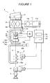
- Figure 1 is a diagram showing the configuration of a winder.
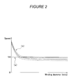
- Figure 2 is a diagram showing the relationship between yarn speed and winding diameter observed where the rotation speed of a drum is controlled to a fixed value.
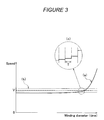
- Figure 3 is a diagram showing the relationship between the peripheral speed of the drum and the winding diameter observed where the yarn speed is controlled to a fixed value.
- Figure 4 is a cone winding package and a drum.
- An embodiment of the present invention will be described.
- An automatic winder will be described with reference to Figure 1.
- The automatic winder rewinds a yarn from a supplying
package 2 produced by a spinning machine or the like to form awinding package 4 of a predetermined shape. The automatic winder comprises a large number of winding units 1 each of which rewinds a single package. - As shown in Figure 1, the
supplying package 2 is placed at the bottom of the winding unit 1, whereas thewinding package 4 is placed at the top of the winding unit 1. An unwinding assistingdevice 5, a variable tension device 6, ayarn splicing device 9, ayarn speed sensor 7, a yarndefect detecting device 8, and atraverse drum 10 are arranged in the winding unit 1 along a route for ayarn 3 extending from the supplyingpackage 2 to thewinding package 4. - The winding unit 1 also comprises a
drum driver 11 that rotationally drives thetraverse drum 10 and asequencer 12 that instructs thedrum driver 11 to control the rotational driving of thetraverse drum 10. - The unwinding assisting
device 5 controls an unwinding balloon that is generated while theyarn 3 is being unwound from the supplyingpackage 2 in its axial direction. - The unwinding assisting
device 5 comprises an umbrella-shapedcylindrical member 51 that covers abobbin 21 for the supplyingpackage 2, and adriving mechanism 52 that lowers thecylindrical member 51 while maintaining a substantially fixed gapf between thecylindrical member 51 and a chess portion of thesupplying package 2. Thecylindrical member 51 is controlled so that it has a substantially fixed balloon diameter during unwinding. - The variable tension device 6 applies a variable winding tension to the
yarn 3 being unwound from the supplyingpackage 2. - The variable tension device 6 comprises fixed
comb teeth 61 andmovable comb teeth 62 alternately arranged opposite one another across the route for theyarn 3, and adriving mechanism 63 such as a solenoid which increases or reduces the amount of engagement between thecomb teeth 61 and thecomb teeth 62. - In accordance with a control signal from the
sequencer 12, the variable tension device 6 controls the amount by which themovable comb teeth 62 engage with the fixedcomb teeth 61, that is, the degree of zigzag bending of the yarn route. The variable tension device 6 can thus sequentially control the winding tension applied to theyarn 3. - The
yarn speed sensor 7 is a device that detects the traveling speed of the yarn 3 (yarn speed) in a non-contact manner. - The
yarn speed sensor 7 comprises a plurality of optical yarn thickness detecting devices along a yarn traveling direction, and theyarn speed sensor 7 utilizes a space filter system to detect the traveling speed of theyarn 3 on the basis of output signals from the yarn detecting means located at different position in the yarn traveling direction. - The optical yarn thickness detecting device comprises a light receiving element and a light source. The quantity of light received by the light receiving element varies depending on the thickness of the
yarn 3 passing at the detection position of the yarn detecting means. The yarn thickness detecting device thus outputs an electric signal corresponding to the yarn thickness. - Upon detecting a yarn defect such as a slab on the
yarn 3, the yarndefect detecting device 8 cuts theyarn 3. - The yarn
defect detecting device 8 comprises a yarnthickness detecting device 81 that detects the thickness of the passingyarn 3, a yarn detect determiningdevice 82 that determines whether or not the yarn thickness corresponds to a yarn defect, and ayarn cutting device 83 that cuts theyarn 3 when it is determined to have a defect. During winding, the thickness of theyarn 3 passing by the yarnthickness detecting device 81 is input to the yarndefect determining device 82 as an electric signal. The yarndefect determining device 82 arithmetically compares the electric signal for the yarn thickness with a reference value. When the electric signal exceeds a tolerance, the yarndefect determining device 82 determines that a yarn defect has passed by and immediately outputs a yarn cut instruction signal to theyarn cutting device 83. Theyarn cutting device 83 is then actuated to forcibly cut the yarn. - Simultaneously with the yarn cutting, a yarn traveling signal from the
yarn cutting device 81 is turned off. The yarndefect determining device 82 senses the yarn breakage and transmits a stop signal for thetraverse drum 10 to thedrum driver 11 via thesequencer 12. This stops rotating thetraverse drum 10. - The yarn
thickness detecting device 81, provided in the yarndefect detecting device 8, also comprises a light receiving element and a light source. The yarn thickness detecting device outputs an electric signal for the yarn thickness. - The
yarn splicing device 9 splices a lower yarn of the supplyingpackage 2 side and an upper yarn of the windingpackage 4 side. When a yarn breakage results from yarn cutting or the like carried out by yarndefect detecting device 8, theyarn 3 is separated into an upper yarn and a lower yarn. Thus, theyarn splicing device 9 carries out splicing to resume rewinding the yarn around the windingpackage 4. When the yarn traveling signal from the yarnthickness detecting device 81 is turned off, the yarndefect determining device 82 transmits a yarn splicing instruction signal to theyarn splicing device 9 via thesequencer 12 in order to actuate theyarn splicing device 9. - The
yarn splicing device 9 comprises anair nozzle device 91 that uses an air current to entangle fibers of the upper and lower yarns with one another for splicing, a loweryarn sucking device 92 that sucks, catches, and guides the lower yarn to theair nozzle device 91, and an upperyarn sucking device 93 that sucks, catches, and guides the upper yarn to theair nozzle device 91. - The lower
yarn sucking device 92 comprises a main body composed of a suction pipe that sucks and catches theyarn 3, and asuction port 92a at the leading end of the suction pipe is pivotable around anaxis 92b at the trailing end of the suction pipe. Vertical pivoting of the suction pipe moves thesuction port 92a between theair nozzle device 91 and a position above the unwinding assistingdevice 5. The upperyarn sucking device 93 is similarly configured. The upperyarn sucking device 93 comprises a main body composed of a suction pipe that sucks and catches theyarn 3. Asuction port 93a at the leading end of the suction pipe is pivotable around anaxis 93b at the trailing end of the suction pipe. Vertical pivoting of the suction pipe moves thesuction port 93a between theair nozzle device 91 and a peripheral surface of the windingpackage 4. - When the yarn
defect detecting device 8 forcibly cuts the yarn on the basis of detection of a yarn defect by the yarndefect detecting device 8, the upper yarn is wound around the windingpackage 4, and on the basis of the yarn splicing instruction signal, the lower yarn is caught by the loweryarn sucking device 92 having thesuction port 92a standing by above the unwinding assistingdevice 5. - Then, on the basis of the yarn splicing instruction signal, the upper yarn is caught by the upper
yarn sucking device 93 having thesuction port 93a standing by over the peripheral surface of the windingpackage 4. - The lower
yarn sucking device 92 subsequently moves thesuction port 92a upward to guide the lower yarn to theair nozzle device 91, and the upperyarn sucking device 93 moves thesuction port 93a downward to guide the upper yarn to theair nozzle device 91. Theair nozzle device 91 splices the upper yarn and lower yarn together. - After the yarn splicing operation, the rotational driving of the
traverse drum 10 is resumed in accordance with an instruction from thesequencer 12. Winding is then carried out again. - The
traverse drum 10 is a device that transversely wounds theyarn 3 into the windingpackage 4. - More specifically, the
traverse drum 10 has a function (traverse means) for swinging theyarn 3 in the axial direction of the windingpackage 4 and a function (winding means) for rotating the windingpackage 4 to wind theyarn 3 on the windingpackage 4. - The function serving as winding means is implemented by forming the
traverse drum 10 into a cylindrical rotating member. Thetraverse drum 10 is placed so that its outer peripheral surface contacts with the outer peripheral surface of the windingpackage 4. In this state, rotation of thetraverse drum 10 rotates the windingpackage 4 in conjunction with thetraverse drum 10. - The function serving as traverse means is implemented by a groove (traverse groove) 10a which is formed in the outer peripheral surface of the
traverse drum 10 and through which theyarn 3 is guided. This groove is formed so as to be displaced in the axial direction of thetraverse drum 10 along its circumferential direction. Theyarn 3 guided through thegroove 10a is swung in the axial direction of thetraverse drum 10 in conjunction with rotation of thetraverse drum 10. - The device that transversely wounds the
yarn 3 into the windingpackage 4 is not limited to thetraverse drum 10 integrally comprising the traverse means and winding means. The device serving as the traverse means may be separated from the device serving as the winding means. For example, the traverse means may be a device that swings the yarn guide in the axial direction of the windingpackage 4, whereas the winding means may be a simple cylindrical rotating member (drum) without any yarn guide groove. - The winding
package 4 is formed by cone winding. - The
bobbin 13 for the windingpackage 4 is shaped like a cone (cylinder shaped like a truncated cone). Theyarn 3 is wound around the outer peripheral surface of thebobbin 13 while being traversed. Consequently, a winding diameter of theyarn 3 is uniform in the axial direction of thebobbin 13. Thus, the windingpackage 4 formed by winding theyarn 3 on thebobbin 13 is conically wound. - The
bobbin 13 is supported by a cradle arm (not shown in the drawings) so that the outer peripheral surface of the winding package 4 (bobbin 13) is always in contact with the outer peripheral surface of thetraverse drum 10. The cradle arm has a supporting position of thebobbin 13 which is varied with an increase in the winding diameter of the windingpackage 4, formed on thebobbin 13. - Since the winding
package 4 andbobbin 13 are cones, thebobbin 13 is supported by the cradle arm so that the lower end of outer peripheral surface of the winding package 4 (bobbin 13) is parallel to the upper end of outer peripheral surface of thetraverse drum 10. This allows the entire lower end of outer peripheral surface of the winding package 4 (bobbin 13) to be kept in contact with the entire upper end of outer peripheral surface of thetraverse drum 10. Thebobbin 13 is thus placed over thetraverse drum 10. - The driving point P (substantial contact point between the winding
package 4 and the traverse drum 10) will be described. - While the
traverse drum 10 is stationary, the entire lower end of outer peripheral surface of the winding package 4 (bobbin 13) is in contact with the entire upper end of outer peripheral surface of thetraverse drum 10. In other words, the outer peripheral surfaces of the windingpackage 4 and traversedrum 10 are in line contact with each other. - In contrast, while the
traverse drum 10 is being rotationally driven, the outer peripheral surfaces of the windingpackage 4 and traversedrum 10 are substantially in point contact with each other at one point. The position of the point contact corresponds to the driving point P. That is, the winding package 4 (bobbin 13) is provided with the rotating force of thetraverse drum 10 only at the driving point P. - The winding package 4 (bobbin 13) is provided with the rotating force only at the driving point P for the following reason.
- Since the winding package 4 (bobbin 13) is conical, its outer peripheral length varies in its axial direction. On the other hand, the peripheral speed provided by the
traverse drum 10 is the same regardless of the axial position on the winding package 4 (bobbin 13). When the winding package 4 (bobbin 13) is provided with the same peripheral speed at its different axial positions, this means that the winding package 4 (bobbin 13) is provided with different rotation speeds owing to its varying outer peripheral length. Where the winding package 4 (bobbin 13) has a stable shape, it is impossible that the rotation speed of the windingpackage 4 varies at different axial positions. Consequently, the rotating force of thetraverse drum 10 is substantially transmitted to the winding package 4 (bobbin 13) only at one axial point (driving point P) on the winding package 4 (bobbin 13). - The driving point P serves as a balancing center position of the winding package 4 (bobbin 13) in contact with the
traverse drum 10. This balancing center position is determined by a position of the center of gravity of the winding package 4 (bobbin 13) and the magnitude of the supporting force exerted by the cradle arm that exerts to support the opposite axial ends of thebobbin 13. - The position of the center of gravity of the winding package 4 (bobbin 13) is displaced toward a larger diameter side in response to an increase in winding diameter resulting from the progress of winding of the
yarn 3. - Thus, the driving point P moves toward the larger diameter side of the winding
package 4 as the winding diameter of the windingpackage 4 increases, as shown by arrow A (Figure 1). - With reference to Figure 2, an explanation will be given of problems with the fixed rotation speed of the
traverse drum 10. - For reference, a description will be given of the rotation speed of the
traverse drum 10 which is set at a fixed value regardless of the varying winding diameter of the windingpackage 4. The fixed rotation speed of thetraverse drum 10 disadvantageously prevents the yarn speed from being fixed. - To prevent this problem, the winding unit 1 includes a yarn speed control mechanism 15 that is able to control the yarn speed at the fixed yarn speed. The yarn speed control mechanism 15 will be described later.
- A line (a) in Figure 2 shows the relationship between the peripheral speed and winding diameter of the
traverse drum 10. The peripheral speed Vd is shown by a thick solid line. The peripheral speed Vd has a fixed value. - A line (b) in Figure 2 shows the relationship between the traveling speed (yarn speed) of the
yarn 3 and the winding diameter. The average value of the yarn speed (traverse average value described later) is shown by a thick broken line. Thin broken lines are used to show the upper limit and lower limit of yarn speed instantaneous value, which varies across the average value. Theyarn speed sensor 7 detects the yarn speed instantaneous value. - The axis of abscissa in Figure 2 is a magnitude axis indicating the winding diameter of the winding
package 4. The axis of ordinate in the figure 2 is a speed axis indicating the yarn speed or peripheral speed. - The line (a) in Figure 2 does not show the rotation speed of the
traverse drum 10 but its peripheral speed because the yarn speed does not correspond to the rotation speed of thetraverse drum 10 but to its peripheral speed. This will be described later in detail. The peripheral speed of thetraverse drum 10 is determined by the rotation speed of thetraverse drum 10 and its diameter. - The winding diameter of the winding
package 4 increases as the time elapses. Accordingly, the axis of abscissa in Figure 2 is generally a time axis. - Where the peripheral speed (rotation speed) of the
traverse drum 10 is fixed as the line (a) in Figure 2, the yarn speed gradually decreases as the line (b) in Figure 2 with increasing winding diameter of the windingpackage 4. - In the present embodiment, at the winding start stage of the winding package 4 (while the winding diameter is smaller), the yarn speed is higher than the fixed peripheral speed of the
traverse drum 10. At the winding end stage of the winding package 4 (while the winding diameter is larger), the yarn speed is lower than the peripheral speed of thetraverse drum 10. - That is, the yarn speed varies with the winding diameter of the winding
package 4. - As described above, where the yarn speed varies with the winding diameter of the winding
package 4, theyarn 3 is formed into the windingpackage 4 with a varying tension. This may degrade the package shape and yarn unwinding ability. Further, where the yarn speed varies over a wide range, the allowable speeds of the devices (unwinding assistingdevice 5, variable tension device 6, and the like) arranged on the yarn route are limited. That is, the devices arranged on the yarn route need to be configured to withstand speeds higher than the average yarn speed from winding start to winding end. This is the problem resulting from an unfixed yarn speed. - Factors determining the yarn speed will be explained.
- The yarn speed is generally in proportion to the rotation speed of the winding
package 4. - This is because when wound into the winding
package 4, theyarn 3 is pulled to travel on the yarn route in the winding unit 1. In the winding unit 1, the only driving means for allowing theyarn 3 to travel is thetraverse drum 10, which rotates the windingpackage 4. - Where the rotation speed of the
traverse drum 10 is the fixed rotation speed, the rotation speed of the windingpackage 4 varies by the displacement of the driving point P as described above. - The rotation speed of the winding
package 4 decreases as the driving point P is displaced toward the larger diameter side in response to an increase in winding diameter. The reason is as follows. - Where the rotation speed of the
traverse drum 10 is the fixed rotation speed, the peripheral speed of thetraverse drum 10 is the fixed peripheral speed. Further, thetraverse drum 10 is substantially in contact with the windingpackage 4 only at the driving point P. The windingpackage 4 is provided with the fixed peripheral speed by thetraverse drum 10 at the driving point P. When the driving point P moves toward the larger diameter side with the peripheral speed of thetraverse drum 10 fixed, the outer peripheral length of the windingpackage 4 at the driving point P increases. This in turn increases the time required to cause the windingpackage 4 to make one rotation. In other words, the displacement of the driving point P toward the larger diameter side reduces the rotation speed of the windingpackage 4. Moreover, the increase in winding diameter itself generally increases the outer peripheral length of the windingpackage 4. - Thus, with an increase in the winding diameter of the winding
package 4, a combination of the displacement of the driving point P toward the larger diameter side and the increase in winding diameter itself increases the outer peripheral length. This contributes to reducing the rotation speed of the windingpackage 4. The line (b) in Figure 2 reflects this situation. - The yarn speed will be described in further detail with reference to Figure 2.
- Since the
yarn 3 is transversely wound into the windingpackage 4, the yarn speed instantaneous value varies in accordance with a traverse winding period (a traverse period). The range of variations in yarn speed is shown by the upper and lower thin broken lines (b) in Figure 2. The reason is as follows. - The yarn speed instantaneous value is generally equal to the peripheral speed of the winding
package 4 at the actual winding position of theyarn 3. For the windingpackage 4 shaped like a cone, even with the fixed rotation speed of the windingpackage 4, the peripheral speed of the windingpackage 4 varies depending on the axial position on the windingpackage 4. Further, since theyarn 3 is transversely wound into the windingpackage 4, the position where theyarn 3 is wound on the windingpackage 4 varies from moment to moment. - Furthermore, during transverse winding, the
yarn 3 is swung in the axial direction of the windingpackage 4. This varies the length of the route for theyarn 3, extending from thetraverse drum 10 to the windingpackage 4, to expand or contract theyarn 3. This in turn causes the yarn speed instantaneous value to deviate from the peripheral speed of the windingpackage 4 at the winding position. - The above variation in yarn speed caused by traverse winding is negligibly small compared to a variation in yarn speed caused by the displaced driving point P. Thus, instead of the yarn speed instantaneous value, the traverse average value of the yarn speed obtained by averaging instantaneous values over the traverse winding period (the traverse period) may be considered a target to be affected by the varying winding diameter of the winding
package 4. - With reference to Figure 1, a description will be given of the yarn speed control mechanism 15, which controls the yarn speed.
- In the description of the yarn speed control mechanism 15, the yarn speed means the traverse average value of the yarn speed, unless otherwise specified.
- The yarn speed control mechanism 15 controls the yarn speed so that it follows a target value. In the yarn speed control mechanism 15, setting a fixed yarn speed target value enables the yarn speed to be controlled to the fixed value, regardless of the varying winding diameter in order to prevent a variation in yarn speed resulting from the varying winding diameter.
- The yarn speed control mechanism 15 comprises the
traverse drum 10, which allows theyarn 3 to travel, thedrum driver 11, which rotationally drives thetraverse drum 10, thesequencer 12 as a control device that controls the rotation speed of thetraverse drum 10, and theyarn speed sensor 7, which detects the yarn speed instantaneous value. - The
sequencer 12 calculates the traverse average value of the yarn speed from the yarn speed instantaneous value detected by theyarn speed sensor 7, and thesequencer 12 controls the rotational driving of thetraverse drum 10 via thedrum driver 11 so that the traverse average value is equal to a predetermined target value. - The
drum driver 11 comprises a drivingmotor 11 a that rotationally drives thetraverse drum 10 and aninverter 11 b that varies an output from the drivingmotor 11 a. - The
sequencer 12 will be described in further detail. - The
sequencer 12 is a computer apparatus comprising anarithmetic device 12a that executes data processing on the basis of programs and astorage device 12b in which data and the programs are stored. Thesequencer 12 is connected to theyarn speed sensor 7 and drumdriver 11 so that it can transmit signals to and from theyarn speed sensor 7 and drumdriver 11 via an input/output device provided in thesequencer 12. - A description will be given of calculation of the traverse average value of the yarn speed executed by the
sequencer 12. - An output signal from the
yarn speed sensor 7 corresponds to the yarn speed instantaneous value. Accordingly, thesequencer 12 calculates the traverse average value of the yarn speed. - Information on the rotation speed of the
traverse drum 10, which also functions as traverse means, is stored in thestorage device 12b of thesequencer 12 in a time series manner. Thearithmetic device 12a calculates the current traverse period from the rotation speed information. Thearithmetic device 12a then averages, over the traverse period, yarn speed instantaneous values transmitted by theyarn speed sensor 7 to calculate the traverse average value of the yarn speed. - In the above description, the
yarn speed sensor 7 and thesequencer 12 constitute yarn speed (traverse average value) detecting means. - The
yarn speed sequencer 7 constitutes means for detecting the yarn speed instantaneous value. - The
sequencer 12 constitutes speed averaging means for averaging yarn speed instantaneous values over the traverse period to calculate the traverse average value of the yarn speed. - The time width over which yarn speed instantaneous values are averaged is not limited to one traverse period (present embodiment). The time width may be a constant multiple of the traverse period.
- Strictly speaking, the
yarn speed sensor 7 cannot be used to determine the yarn speed instantaneous value. This is because the time width required to detect the yarn speed varies depending on the yarn speed. - With the space filter system, the magnitude of frequency, from which the yarn speed is determined, varies depending on the yarn speed, and this varies the time required to detect the yarn speed. Further, with an encoder, the intervals of pulse transmissions, from which the yarn speed is determined, varies depending on the yarn speed, and this varies the time required to detect the yarn speed.
- However, the time width required to detect the yarn speed corresponds to the amount of time until a specified point on the
yarn 3 passes by theyarn speed sensor 7. This time is thus much smaller than the traverse period. Accordingly, in connection with the traverse period, the yarn speed detected by theyarn speed sensor 7 can be considered to be its instantaneous value. - The
sequencer 12 compares the yarn speed detected value with the yarn speed target value stored in thestorage device 12b. The yarn speed target value, set at a specified value, is stored in thestorage device 12b. The target value can be changed via an input device for thesequencer 12. - The
sequencer 12 controls the rotation speed of thetraverse drum 10 so that the yarn speed detected value is equal to the yarn speed target value. This rotation speed control is performed by changing or maintaining an instruction value for the rotation speed of thetraverse drum 10 with respect to the last instruction value. - Specifically, when the yarn speed detected value is larger than the yarn speed target value, the
sequencer 12 sets the instruction value for the rotation speed of thetraverse drum 10 to be smaller than the last one so as to lower the rotation speed of thetraverse drum 10. In contrast, when the yarn speed detected value is smaller than the yarn speed target value, thesequencer 12 sets the instruction value for the rotation speed of thetraverse drum 10 to be larger than the last one so as to raise the rotation speed of thetraverse drum 10. When the yarn speed detected value is equal to the yarn speed target value, thesequencer 12 sets the instruction value for the rotation speed of thetraverse drum 10 to be the same as the last one so as to maintain the rotation speed of thetraverse drum 10. - An
encoder 16 that is a rotation speed detecting device is provided in the winding unit 1 to serve as means for obtaining the detected value of rotation speed of thetraverse drum 10. The detected value (detected value of rotation speed of the traverse drum 10) obtained by theencoder 16 is transmitted to thesequencer 12. - The
sequencer 12 determines whether or not the detected value of rotation speed of thetraverse drum 10 is equal to the instruction value for the rotation speed of thetraverse drum 10 to monitor whether or not thedrum driver 11 operates improperly. The detected value itself of rotation speed of thetraverse drum 10 is not utilized for thesequencer 12 to control the yarn speed so that it follows the target value. - With reference to Figure 3, a description will be given of variations in yarn speed and in the rotation speed of the
traverse drum 10 which are observed where the yarn speed control mechanism 15 controls the yarn speed to a fixed value. - A line (a) in Figure 3 shows the relationship between the peripheral speed of the
traverse drum 10 and the winding diameter. The peripheral speed is shown by a thick solid line. The peripheral speed is controlled to increase consistently with the winding diameter. - A line (b) in Figure 3 shows the relationship between the yarn speed and the winding diameter. The average value V (traverse average value) of the yarn speed is shown by a thick broken line. Thin broken lines are used to show the upper limit and lower limit of yarn speed instantaneous value, which varies across the average value. The
yarn speed sensor 7 detects the yarn speed instantaneous value. - The axis of abscissa in Figure 3 is a magnitude axis indicating the winding diameter of the winding
package 4. The axis of ordinate in the figure 3 is a speed axis indicating the yarn speed or peripheral speed. - Where the yarn speed is controlled to a fixed value as the line (b) in Figure 3, the peripheral speed (rotation speed) of the
traverse drum 10 gradually increases as the line (a) in Figure 3. - In the present embodiment, at the winding start stage of the winding package 4 (while the winding diameter is smaller), the peripheral speed is lower than the fixed yarn speed. At the winding end stage of the winding package 4 (while the winding diameter is larger), the peripheral speed is higher than the yarn speed.
- A line (c) in Figure 3 shows a partial enlarged view of the line (a) in Figure 3.
- The peripheral speed of the
traverse drum 10 generally increases gradually as the line (a) in Figure 3 while forming a step-like waveform as the line (c) in Figure 3. - This is because the
sequencer 12 in the yarn speed control mechanism 15 changes the instruction value for the rotation speed of thetraverse drum 10 at every traverse period T. The setting (change or maintenance) of the instruction value for the rotation speed is based on the traverse average value of the yarn speed. The setting follows timings for the calculation of the traverse average value of the yarn speed.
In the above description, the yarn speed control mechanism 15 controls the yarn speed so that its actual value is equal to the fixed target value. However, the yarn speed target value may be set to vary with the winding diameter (time elapse). To vary the tension between the winding start and winding end of the package, the yarn speed control mechanism 15 may be used to adjust the yarn speed in accordance with the winding diameter.
Claims (3)
- A winder comprising:a drum that rotates in contact with a package to concurrently rotate the package; and a drum driver that rotationally drives the drum, the winder being characterized by further comprising:yarn speed detecting means for detecting a yarn speed that is a traveling speed of a yarn being wound into a package; anda control device that controls the drum driver by setting an instruction value for a rotation speed of the drum so that a detected value of the yarn speed is equal to a target value of the yarn speed.
- A winder according to Claim 1, characterized in that the target value of the yarn speed is a predetermined fixed value.
- A winder according to Claim 1 or Claim 2, characterized in that the drum is a traverse drum having an outer peripheral surface in which a traverse groove is formed.
Applications Claiming Priority (1)
| Application Number | Priority Date | Filing Date | Title |
|---|---|---|---|
| JP2005355303A JP4712549B2 (en) | 2005-12-08 | 2005-12-08 | Winder |
Publications (2)
| Publication Number | Publication Date |
|---|---|
| EP1795477A1 true EP1795477A1 (en) | 2007-06-13 |
| EP1795477B1 EP1795477B1 (en) | 2009-09-16 |
Family
ID=37846037
Family Applications (1)
| Application Number | Title | Priority Date | Filing Date |
|---|---|---|---|
| EP20060124374 Active EP1795477B1 (en) | 2005-12-08 | 2006-11-20 | Winder |
Country Status (3)
| Country | Link |
|---|---|
| EP (1) | EP1795477B1 (en) |
| JP (1) | JP4712549B2 (en) |
| DE (1) | DE602006009207D1 (en) |
Cited By (4)
| Publication number | Priority date | Publication date | Assignee | Title |
|---|---|---|---|---|
| WO2009127662A1 (en) * | 2008-04-15 | 2009-10-22 | Vienco Gmbh | Method and apparatus for highly-precise determination of the instantaneous winding speed of a moving thread |
| EP2090538A3 (en) * | 2008-02-14 | 2010-09-29 | Murata Machinery, Ltd. | Yarn quality measuring instrument and yarn winding machine |
| EP2690043A3 (en) * | 2012-07-27 | 2015-05-06 | Murata Machinery, Ltd. | Driving state detecting device, winding unit, winding machine, spinning unit, and spinning machine |
| CN111683888A (en) * | 2018-02-07 | 2020-09-18 | 村田机械株式会社 | Yarn winding machine and yarn winding method |
Citations (6)
| Publication number | Priority date | Publication date | Assignee | Title |
|---|---|---|---|---|
| US4049211A (en) * | 1975-11-05 | 1977-09-20 | Rieter Machine Works, Ltd. | Winding apparatus for textile threads |
| DE2626504A1 (en) * | 1974-01-24 | 1977-12-29 | Schlafhorst & Co W | Winding station for conical cross-wound spools - ensures uniform winding at higher speeds, without excess at package ends |
| EP0165511A2 (en) * | 1984-06-19 | 1985-12-27 | Schubert & Salzer Maschinenfabrik Aktiengesellschaft | Device for winding a yarn supplied at a constant speed on a conical spool |
| EP0343540A1 (en) * | 1988-05-25 | 1989-11-29 | ELITEX koncern textilniho strojirenstvi | Method and device for winding up a yarn to a cone, especially in a textile machine with constant yarn supply |
| EP0950627A1 (en) * | 1998-04-17 | 1999-10-20 | Schärer Schweiter Mettler AG | Method and device for winding a yarn fed with constant speed onto a bobbin |
| EP1553037A1 (en) * | 2004-01-06 | 2005-07-13 | Murata Kikai Kabushiki Kaisha | Winding device of spun yarn |
Family Cites Families (4)
| Publication number | Priority date | Publication date | Assignee | Title |
|---|---|---|---|---|
| CH675132A5 (en) * | 1987-09-01 | 1990-08-31 | Zellweger Uster Ag | |
| JPH04341463A (en) * | 1991-05-17 | 1992-11-27 | Murata Mach Ltd | Pirn winder drive method |
| JP3275189B2 (en) * | 1993-09-21 | 2002-04-15 | 株式会社神津製作所 | Method and apparatus for winding high elongation yarn |
| DE59809204D1 (en) * | 1998-02-14 | 2003-09-11 | Volkmann Gmbh | Method and device for winding yarn onto a conical bobbin |
-
2005
- 2005-12-08 JP JP2005355303A patent/JP4712549B2/en not_active Expired - Fee Related
-
2006
- 2006-11-20 DE DE200660009207 patent/DE602006009207D1/en active Active
- 2006-11-20 EP EP20060124374 patent/EP1795477B1/en active Active
Patent Citations (6)
| Publication number | Priority date | Publication date | Assignee | Title |
|---|---|---|---|---|
| DE2626504A1 (en) * | 1974-01-24 | 1977-12-29 | Schlafhorst & Co W | Winding station for conical cross-wound spools - ensures uniform winding at higher speeds, without excess at package ends |
| US4049211A (en) * | 1975-11-05 | 1977-09-20 | Rieter Machine Works, Ltd. | Winding apparatus for textile threads |
| EP0165511A2 (en) * | 1984-06-19 | 1985-12-27 | Schubert & Salzer Maschinenfabrik Aktiengesellschaft | Device for winding a yarn supplied at a constant speed on a conical spool |
| EP0343540A1 (en) * | 1988-05-25 | 1989-11-29 | ELITEX koncern textilniho strojirenstvi | Method and device for winding up a yarn to a cone, especially in a textile machine with constant yarn supply |
| EP0950627A1 (en) * | 1998-04-17 | 1999-10-20 | Schärer Schweiter Mettler AG | Method and device for winding a yarn fed with constant speed onto a bobbin |
| EP1553037A1 (en) * | 2004-01-06 | 2005-07-13 | Murata Kikai Kabushiki Kaisha | Winding device of spun yarn |
Cited By (4)
| Publication number | Priority date | Publication date | Assignee | Title |
|---|---|---|---|---|
| EP2090538A3 (en) * | 2008-02-14 | 2010-09-29 | Murata Machinery, Ltd. | Yarn quality measuring instrument and yarn winding machine |
| WO2009127662A1 (en) * | 2008-04-15 | 2009-10-22 | Vienco Gmbh | Method and apparatus for highly-precise determination of the instantaneous winding speed of a moving thread |
| EP2690043A3 (en) * | 2012-07-27 | 2015-05-06 | Murata Machinery, Ltd. | Driving state detecting device, winding unit, winding machine, spinning unit, and spinning machine |
| CN111683888A (en) * | 2018-02-07 | 2020-09-18 | 村田机械株式会社 | Yarn winding machine and yarn winding method |
Also Published As
| Publication number | Publication date |
|---|---|
| JP4712549B2 (en) | 2011-06-29 |
| JP2007153608A (en) | 2007-06-21 |
| EP1795477B1 (en) | 2009-09-16 |
| DE602006009207D1 (en) | 2009-10-29 |
Similar Documents
| Publication | Publication Date | Title |
|---|---|---|
| EP2479130B1 (en) | Yarn winding device | |
| CN104925584B (en) | Yarn winding machine and winding method | |
| EP1882663B1 (en) | Device for pulling out a yarn end from a winding package | |
| EP2159180B1 (en) | Yarn winding device and automatic winder | |
| EP2159181B1 (en) | Yarn winding device and automatic winder comprising the same | |
| EP2690046A2 (en) | Yarn defect detecting device and winding device | |
| US5595351A (en) | Method for controlling a winding station of a bobbin winding machine when a take-up bobbin is changed and winding station for performing the method | |
| JP2016013892A (en) | Yarn winder | |
| EP2105399A2 (en) | Yarn Winding Device and Yarn Winding Method | |
| EP2808283A1 (en) | Yarn winding machine | |
| JP2015000777A (en) | Yarn winding machine | |
| CN102574655B (en) | Yarn winder | |
| JP2010042904A (en) | Yarn winding machine | |
| EP2530040B1 (en) | Yarn winding device | |
| EP2402274B1 (en) | Yarn winding device | |
| JP2009208880A (en) | Yarn winding device and yarn winding method | |
| EP1795477B1 (en) | Winder | |
| JPH10114537A (en) | Optical fiber screening apparatus and optical fiber screening method | |
| US6533211B2 (en) | Method of operating a textile machine for producing cheeses | |
| EP1795478B1 (en) | Textile machine | |
| EP2690044B1 (en) | Yarn winding device | |
| CN111132918B (en) | Yarn winding machine | |
| JP2013154991A (en) | Yarn winding machine and yarn winding method | |
| CN111683888B (en) | Yarn winding machine and yarn winding method | |
| EP4197949B1 (en) | Yarn winding machine |
Legal Events
| Date | Code | Title | Description |
|---|---|---|---|
| PUAI | Public reference made under article 153(3) epc to a published international application that has entered the european phase |
Free format text: ORIGINAL CODE: 0009012 |
|
| AK | Designated contracting states |
Kind code of ref document: A1 Designated state(s): AT BE BG CH CY CZ DE DK EE ES FI FR GB GR HU IE IS IT LI LT LU LV MC NL PL PT RO SE SI SK TR |
|
| AX | Request for extension of the european patent |
Extension state: AL BA HR MK YU |
|
| 17P | Request for examination filed |
Effective date: 20071213 |
|
| 17Q | First examination report despatched |
Effective date: 20080114 |
|
| AKX | Designation fees paid |
Designated state(s): DE IT |
|
| GRAP | Despatch of communication of intention to grant a patent |
Free format text: ORIGINAL CODE: EPIDOSNIGR1 |
|
| GRAS | Grant fee paid |
Free format text: ORIGINAL CODE: EPIDOSNIGR3 |
|
| GRAA | (expected) grant |
Free format text: ORIGINAL CODE: 0009210 |
|
| AK | Designated contracting states |
Kind code of ref document: B1 Designated state(s): DE IT |
|
| REF | Corresponds to: |
Ref document number: 602006009207 Country of ref document: DE Date of ref document: 20091029 Kind code of ref document: P |
|
| PLBE | No opposition filed within time limit |
Free format text: ORIGINAL CODE: 0009261 |
|
| STAA | Information on the status of an ep patent application or granted ep patent |
Free format text: STATUS: NO OPPOSITION FILED WITHIN TIME LIMIT |
|
| 26N | No opposition filed |
Effective date: 20100617 |
|
| PGFP | Annual fee paid to national office [announced via postgrant information from national office to epo] |
Ref country code: DE Payment date: 20241022 Year of fee payment: 19 |
|
| PGFP | Annual fee paid to national office [announced via postgrant information from national office to epo] |
Ref country code: IT Payment date: 20241022 Year of fee payment: 19 |