EP1795449B1 - Flat container comprising thermoplastic resin and method for molding the same - Google Patents
Flat container comprising thermoplastic resin and method for molding the same Download PDFInfo
- Publication number
- EP1795449B1 EP1795449B1 EP05785865A EP05785865A EP1795449B1 EP 1795449 B1 EP1795449 B1 EP 1795449B1 EP 05785865 A EP05785865 A EP 05785865A EP 05785865 A EP05785865 A EP 05785865A EP 1795449 B1 EP1795449 B1 EP 1795449B1
- Authority
- EP
- European Patent Office
- Prior art keywords
- container
- flat
- wall thickness
- mold
- blow molding
- Prior art date
- Legal status (The legal status is an assumption and is not a legal conclusion. Google has not performed a legal analysis and makes no representation as to the accuracy of the status listed.)
- Active
Links
- 229920005992 thermoplastic resin Polymers 0.000 title claims description 9
- 238000000465 moulding Methods 0.000 title description 35
- 238000000034 method Methods 0.000 title description 27
- 238000000071 blow moulding Methods 0.000 claims abstract description 76
- 230000008859 change Effects 0.000 claims abstract description 27
- 229920001225 polyester resin Polymers 0.000 claims abstract description 26
- 239000004645 polyester resin Substances 0.000 claims abstract description 26
- 238000009864 tensile test Methods 0.000 claims abstract description 13
- 229920000139 polyethylene terephthalate Polymers 0.000 claims description 15
- 239000005020 polyethylene terephthalate Substances 0.000 claims description 15
- -1 polyethylene terephthalate Polymers 0.000 claims description 7
- 238000004519 manufacturing process Methods 0.000 abstract description 9
- 238000007664 blowing Methods 0.000 description 29
- 230000000052 comparative effect Effects 0.000 description 20
- 235000013361 beverage Nutrition 0.000 description 17
- 238000005259 measurement Methods 0.000 description 13
- 230000000994 depressogenic effect Effects 0.000 description 12
- 230000037303 wrinkles Effects 0.000 description 11
- 238000012360 testing method Methods 0.000 description 10
- 238000002474 experimental method Methods 0.000 description 8
- 239000000463 material Substances 0.000 description 8
- 229920005989 resin Polymers 0.000 description 8
- 239000011347 resin Substances 0.000 description 8
- LYCAIKOWRPUZTN-UHFFFAOYSA-N Ethylene glycol Chemical compound OCCO LYCAIKOWRPUZTN-UHFFFAOYSA-N 0.000 description 7
- 238000004381 surface treatment Methods 0.000 description 7
- 239000011248 coating agent Substances 0.000 description 6
- 239000000470 constituent Substances 0.000 description 6
- 230000000704 physical effect Effects 0.000 description 6
- QVGXLLKOCUKJST-UHFFFAOYSA-N atomic oxygen Chemical compound [O] QVGXLLKOCUKJST-UHFFFAOYSA-N 0.000 description 5
- 230000015572 biosynthetic process Effects 0.000 description 5
- 238000000576 coating method Methods 0.000 description 5
- 239000001301 oxygen Substances 0.000 description 5
- 229910052760 oxygen Inorganic materials 0.000 description 5
- 238000007796 conventional method Methods 0.000 description 4
- 238000001816 cooling Methods 0.000 description 4
- 150000004291 polyenes Chemical class 0.000 description 4
- DNIAPMSPPWPWGF-UHFFFAOYSA-N Propylene glycol Chemical compound CC(O)CO DNIAPMSPPWPWGF-UHFFFAOYSA-N 0.000 description 3
- 239000013078 crystal Substances 0.000 description 3
- 238000002425 crystallisation Methods 0.000 description 3
- 230000008025 crystallization Effects 0.000 description 3
- MTHSVFCYNBDYFN-UHFFFAOYSA-N diethylene glycol Chemical compound OCCOCCO MTHSVFCYNBDYFN-UHFFFAOYSA-N 0.000 description 3
- 238000010438 heat treatment Methods 0.000 description 3
- 239000004033 plastic Substances 0.000 description 3
- 229920003023 plastic Polymers 0.000 description 3
- 230000008569 process Effects 0.000 description 3
- XLYOFNOQVPJJNP-UHFFFAOYSA-N water Substances O XLYOFNOQVPJJNP-UHFFFAOYSA-N 0.000 description 3
- KKEYFWRCBNTPAC-UHFFFAOYSA-N Terephthalic acid Chemical compound OC(=O)C1=CC=C(C(O)=O)C=C1 KKEYFWRCBNTPAC-UHFFFAOYSA-N 0.000 description 2
- 239000006096 absorbing agent Substances 0.000 description 2
- 239000002253 acid Substances 0.000 description 2
- 238000004458 analytical method Methods 0.000 description 2
- 230000000903 blocking effect Effects 0.000 description 2
- WERYXYBDKMZEQL-UHFFFAOYSA-N butane-1,4-diol Chemical compound OCCCCO WERYXYBDKMZEQL-UHFFFAOYSA-N 0.000 description 2
- 230000000875 corresponding effect Effects 0.000 description 2
- 238000011156 evaluation Methods 0.000 description 2
- 239000012530 fluid Substances 0.000 description 2
- 238000000265 homogenisation Methods 0.000 description 2
- WGCNASOHLSPBMP-UHFFFAOYSA-N hydroxyacetaldehyde Natural products OCC=O WGCNASOHLSPBMP-UHFFFAOYSA-N 0.000 description 2
- 230000006872 improvement Effects 0.000 description 2
- 238000010102 injection blow moulding Methods 0.000 description 2
- QQVIHTHCMHWDBS-UHFFFAOYSA-N isophthalic acid Chemical compound OC(=O)C1=CC=CC(C(O)=O)=C1 QQVIHTHCMHWDBS-UHFFFAOYSA-N 0.000 description 2
- 229920001343 polytetrafluoroethylene Polymers 0.000 description 2
- 239000004810 polytetrafluoroethylene Substances 0.000 description 2
- 238000007788 roughening Methods 0.000 description 2
- 238000005070 sampling Methods 0.000 description 2
- 238000007493 shaping process Methods 0.000 description 2
- 230000000930 thermomechanical effect Effects 0.000 description 2
- LLLVZDVNHNWSDS-UHFFFAOYSA-N 4-methylidene-3,5-dioxabicyclo[5.2.2]undeca-1(9),7,10-triene-2,6-dione Chemical group C1(C2=CC=C(C(=O)OC(=C)O1)C=C2)=O LLLVZDVNHNWSDS-UHFFFAOYSA-N 0.000 description 1
- 239000004952 Polyamide Substances 0.000 description 1
- 239000004698 Polyethylene Substances 0.000 description 1
- 239000004743 Polypropylene Substances 0.000 description 1
- 238000010521 absorption reaction Methods 0.000 description 1
- 238000009825 accumulation Methods 0.000 description 1
- 230000009471 action Effects 0.000 description 1
- 239000000654 additive Substances 0.000 description 1
- 239000003242 anti bacterial agent Substances 0.000 description 1
- 239000003963 antioxidant agent Substances 0.000 description 1
- 230000003078 antioxidant effect Effects 0.000 description 1
- 230000008901 benefit Effects 0.000 description 1
- 125000004432 carbon atom Chemical group C* 0.000 description 1
- 238000004140 cleaning Methods 0.000 description 1
- 230000003749 cleanliness Effects 0.000 description 1
- 239000003086 colorant Substances 0.000 description 1
- 229920001577 copolymer Polymers 0.000 description 1
- 230000002596 correlated effect Effects 0.000 description 1
- 229920006038 crystalline resin Polymers 0.000 description 1
- 125000004122 cyclic group Chemical group 0.000 description 1
- VEIOBOXBGYWJIT-UHFFFAOYSA-N cyclohexane;methanol Chemical compound OC.OC.C1CCCCC1 VEIOBOXBGYWJIT-UHFFFAOYSA-N 0.000 description 1
- 238000011161 development Methods 0.000 description 1
- 238000010586 diagram Methods 0.000 description 1
- BXKDSDJJOVIHMX-UHFFFAOYSA-N edrophonium chloride Chemical compound [Cl-].CC[N+](C)(C)C1=CC=CC(O)=C1 BXKDSDJJOVIHMX-UHFFFAOYSA-N 0.000 description 1
- 230000007613 environmental effect Effects 0.000 description 1
- 238000001125 extrusion Methods 0.000 description 1
- 230000009477 glass transition Effects 0.000 description 1
- 238000001746 injection moulding Methods 0.000 description 1
- 238000010030 laminating Methods 0.000 description 1
- 239000007788 liquid Substances 0.000 description 1
- 238000000691 measurement method Methods 0.000 description 1
- 229940127554 medical product Drugs 0.000 description 1
- 239000000203 mixture Substances 0.000 description 1
- 238000010137 moulding (plastic) Methods 0.000 description 1
- KYTZHLUVELPASH-UHFFFAOYSA-N naphthalene-1,2-dicarboxylic acid Chemical compound C1=CC=CC2=C(C(O)=O)C(C(=O)O)=CC=C21 KYTZHLUVELPASH-UHFFFAOYSA-N 0.000 description 1
- 238000009928 pasteurization Methods 0.000 description 1
- 229920002647 polyamide Polymers 0.000 description 1
- 229920000515 polycarbonate Polymers 0.000 description 1
- 239000004417 polycarbonate Substances 0.000 description 1
- 229920000573 polyethylene Polymers 0.000 description 1
- 229920000642 polymer Polymers 0.000 description 1
- 229920000098 polyolefin Polymers 0.000 description 1
- 229920000379 polypropylene carbonate Polymers 0.000 description 1
- 238000005488 sandblasting Methods 0.000 description 1
- 238000007789 sealing Methods 0.000 description 1
- 229910052710 silicon Inorganic materials 0.000 description 1
- 239000010703 silicon Substances 0.000 description 1
- BFKJFAAPBSQJPD-UHFFFAOYSA-N tetrafluoroethene Chemical group FC(F)=C(F)F BFKJFAAPBSQJPD-UHFFFAOYSA-N 0.000 description 1
- 229920001169 thermoplastic Polymers 0.000 description 1
- 239000004416 thermosoftening plastic Substances 0.000 description 1
- ITRNXVSDJBHYNJ-UHFFFAOYSA-N tungsten disulfide Chemical compound S=[W]=S ITRNXVSDJBHYNJ-UHFFFAOYSA-N 0.000 description 1
- 238000012795 verification Methods 0.000 description 1
Images


Classifications
-
- B—PERFORMING OPERATIONS; TRANSPORTING
- B29—WORKING OF PLASTICS; WORKING OF SUBSTANCES IN A PLASTIC STATE IN GENERAL
- B29C—SHAPING OR JOINING OF PLASTICS; SHAPING OF MATERIAL IN A PLASTIC STATE, NOT OTHERWISE PROVIDED FOR; AFTER-TREATMENT OF THE SHAPED PRODUCTS, e.g. REPAIRING
- B29C49/00—Blow-moulding, i.e. blowing a preform or parison to a desired shape within a mould; Apparatus therefor
- B29C49/18—Blow-moulding, i.e. blowing a preform or parison to a desired shape within a mould; Apparatus therefor using several blowing steps
-
- B—PERFORMING OPERATIONS; TRANSPORTING
- B29—WORKING OF PLASTICS; WORKING OF SUBSTANCES IN A PLASTIC STATE IN GENERAL
- B29C—SHAPING OR JOINING OF PLASTICS; SHAPING OF MATERIAL IN A PLASTIC STATE, NOT OTHERWISE PROVIDED FOR; AFTER-TREATMENT OF THE SHAPED PRODUCTS, e.g. REPAIRING
- B29C37/00—Component parts, details, accessories or auxiliary operations, not covered by group B29C33/00 or B29C35/00
- B29C37/0067—Using separating agents during or after moulding; Applying separating agents on preforms or articles, e.g. to prevent sticking to each other
-
- B—PERFORMING OPERATIONS; TRANSPORTING
- B29—WORKING OF PLASTICS; WORKING OF SUBSTANCES IN A PLASTIC STATE IN GENERAL
- B29C—SHAPING OR JOINING OF PLASTICS; SHAPING OF MATERIAL IN A PLASTIC STATE, NOT OTHERWISE PROVIDED FOR; AFTER-TREATMENT OF THE SHAPED PRODUCTS, e.g. REPAIRING
- B29C49/00—Blow-moulding, i.e. blowing a preform or parison to a desired shape within a mould; Apparatus therefor
- B29C49/22—Blow-moulding, i.e. blowing a preform or parison to a desired shape within a mould; Apparatus therefor using multilayered preforms or parisons
-
- B—PERFORMING OPERATIONS; TRANSPORTING
- B29—WORKING OF PLASTICS; WORKING OF SUBSTANCES IN A PLASTIC STATE IN GENERAL
- B29C—SHAPING OR JOINING OF PLASTICS; SHAPING OF MATERIAL IN A PLASTIC STATE, NOT OTHERWISE PROVIDED FOR; AFTER-TREATMENT OF THE SHAPED PRODUCTS, e.g. REPAIRING
- B29C49/00—Blow-moulding, i.e. blowing a preform or parison to a desired shape within a mould; Apparatus therefor
- B29C49/42—Component parts, details or accessories; Auxiliary operations
- B29C49/4242—Means for deforming the parison prior to the blowing operation
-
- B—PERFORMING OPERATIONS; TRANSPORTING
- B29—WORKING OF PLASTICS; WORKING OF SUBSTANCES IN A PLASTIC STATE IN GENERAL
- B29C—SHAPING OR JOINING OF PLASTICS; SHAPING OF MATERIAL IN A PLASTIC STATE, NOT OTHERWISE PROVIDED FOR; AFTER-TREATMENT OF THE SHAPED PRODUCTS, e.g. REPAIRING
- B29C49/00—Blow-moulding, i.e. blowing a preform or parison to a desired shape within a mould; Apparatus therefor
- B29C49/42—Component parts, details or accessories; Auxiliary operations
- B29C49/48—Moulds
-
- B—PERFORMING OPERATIONS; TRANSPORTING
- B65—CONVEYING; PACKING; STORING; HANDLING THIN OR FILAMENTARY MATERIAL
- B65D—CONTAINERS FOR STORAGE OR TRANSPORT OF ARTICLES OR MATERIALS, e.g. BAGS, BARRELS, BOTTLES, BOXES, CANS, CARTONS, CRATES, DRUMS, JARS, TANKS, HOPPERS, FORWARDING CONTAINERS; ACCESSORIES, CLOSURES, OR FITTINGS THEREFOR; PACKAGING ELEMENTS; PACKAGES
- B65D1/00—Containers having bodies formed in one piece, e.g. by casting metallic material, by moulding plastics, by blowing vitreous material, by throwing ceramic material, by moulding pulped fibrous material, by deep-drawing operations performed on sheet material
- B65D1/02—Bottles or similar containers with necks or like restricted apertures, designed for pouring contents
- B65D1/0207—Bottles or similar containers with necks or like restricted apertures, designed for pouring contents characterised by material, e.g. composition, physical features
- B65D1/0215—Bottles or similar containers with necks or like restricted apertures, designed for pouring contents characterised by material, e.g. composition, physical features multilayered
-
- B—PERFORMING OPERATIONS; TRANSPORTING
- B65—CONVEYING; PACKING; STORING; HANDLING THIN OR FILAMENTARY MATERIAL
- B65D—CONTAINERS FOR STORAGE OR TRANSPORT OF ARTICLES OR MATERIALS, e.g. BAGS, BARRELS, BOTTLES, BOXES, CANS, CARTONS, CRATES, DRUMS, JARS, TANKS, HOPPERS, FORWARDING CONTAINERS; ACCESSORIES, CLOSURES, OR FITTINGS THEREFOR; PACKAGING ELEMENTS; PACKAGES
- B65D1/00—Containers having bodies formed in one piece, e.g. by casting metallic material, by moulding plastics, by blowing vitreous material, by throwing ceramic material, by moulding pulped fibrous material, by deep-drawing operations performed on sheet material
- B65D1/02—Bottles or similar containers with necks or like restricted apertures, designed for pouring contents
- B65D1/0223—Bottles or similar containers with necks or like restricted apertures, designed for pouring contents characterised by shape
-
- B—PERFORMING OPERATIONS; TRANSPORTING
- B29—WORKING OF PLASTICS; WORKING OF SUBSTANCES IN A PLASTIC STATE IN GENERAL
- B29C—SHAPING OR JOINING OF PLASTICS; SHAPING OF MATERIAL IN A PLASTIC STATE, NOT OTHERWISE PROVIDED FOR; AFTER-TREATMENT OF THE SHAPED PRODUCTS, e.g. REPAIRING
- B29C49/00—Blow-moulding, i.e. blowing a preform or parison to a desired shape within a mould; Apparatus therefor
- B29C49/42—Component parts, details or accessories; Auxiliary operations
- B29C49/48—Moulds
- B29C2049/4874—Moulds characterised by the material, e.g. having different thermal conductivities or hardness
-
- B—PERFORMING OPERATIONS; TRANSPORTING
- B29—WORKING OF PLASTICS; WORKING OF SUBSTANCES IN A PLASTIC STATE IN GENERAL
- B29C—SHAPING OR JOINING OF PLASTICS; SHAPING OF MATERIAL IN A PLASTIC STATE, NOT OTHERWISE PROVIDED FOR; AFTER-TREATMENT OF THE SHAPED PRODUCTS, e.g. REPAIRING
- B29C49/00—Blow-moulding, i.e. blowing a preform or parison to a desired shape within a mould; Apparatus therefor
- B29C49/42—Component parts, details or accessories; Auxiliary operations
- B29C49/78—Measuring, controlling or regulating
- B29C49/783—Measuring, controlling or regulating blowing pressure
- B29C2049/7831—Measuring, controlling or regulating blowing pressure characterised by pressure values or ranges
-
- B—PERFORMING OPERATIONS; TRANSPORTING
- B29—WORKING OF PLASTICS; WORKING OF SUBSTANCES IN A PLASTIC STATE IN GENERAL
- B29C—SHAPING OR JOINING OF PLASTICS; SHAPING OF MATERIAL IN A PLASTIC STATE, NOT OTHERWISE PROVIDED FOR; AFTER-TREATMENT OF THE SHAPED PRODUCTS, e.g. REPAIRING
- B29C49/00—Blow-moulding, i.e. blowing a preform or parison to a desired shape within a mould; Apparatus therefor
- B29C49/42—Component parts, details or accessories; Auxiliary operations
- B29C49/78—Measuring, controlling or regulating
- B29C2049/7879—Stretching, e.g. stretch rod
-
- B—PERFORMING OPERATIONS; TRANSPORTING
- B29—WORKING OF PLASTICS; WORKING OF SUBSTANCES IN A PLASTIC STATE IN GENERAL
- B29C—SHAPING OR JOINING OF PLASTICS; SHAPING OF MATERIAL IN A PLASTIC STATE, NOT OTHERWISE PROVIDED FOR; AFTER-TREATMENT OF THE SHAPED PRODUCTS, e.g. REPAIRING
- B29C2949/00—Indexing scheme relating to blow-moulding
- B29C2949/07—Preforms or parisons characterised by their configuration
- B29C2949/0715—Preforms or parisons characterised by their configuration the preform having one end closed
-
- B—PERFORMING OPERATIONS; TRANSPORTING
- B29—WORKING OF PLASTICS; WORKING OF SUBSTANCES IN A PLASTIC STATE IN GENERAL
- B29C—SHAPING OR JOINING OF PLASTICS; SHAPING OF MATERIAL IN A PLASTIC STATE, NOT OTHERWISE PROVIDED FOR; AFTER-TREATMENT OF THE SHAPED PRODUCTS, e.g. REPAIRING
- B29C2949/00—Indexing scheme relating to blow-moulding
- B29C2949/07—Preforms or parisons characterised by their configuration
- B29C2949/076—Preforms or parisons characterised by their configuration characterised by the shape
- B29C2949/0768—Preforms or parisons characterised by their configuration characterised by the shape characterised by the shape of specific parts of preform
- B29C2949/077—Preforms or parisons characterised by their configuration characterised by the shape characterised by the shape of specific parts of preform characterised by the neck
- B29C2949/0772—Closure retaining means
- B29C2949/0773—Threads
-
- B—PERFORMING OPERATIONS; TRANSPORTING
- B29—WORKING OF PLASTICS; WORKING OF SUBSTANCES IN A PLASTIC STATE IN GENERAL
- B29C—SHAPING OR JOINING OF PLASTICS; SHAPING OF MATERIAL IN A PLASTIC STATE, NOT OTHERWISE PROVIDED FOR; AFTER-TREATMENT OF THE SHAPED PRODUCTS, e.g. REPAIRING
- B29C2949/00—Indexing scheme relating to blow-moulding
- B29C2949/07—Preforms or parisons characterised by their configuration
- B29C2949/076—Preforms or parisons characterised by their configuration characterised by the shape
- B29C2949/0768—Preforms or parisons characterised by their configuration characterised by the shape characterised by the shape of specific parts of preform
- B29C2949/077—Preforms or parisons characterised by their configuration characterised by the shape characterised by the shape of specific parts of preform characterised by the neck
- B29C2949/0777—Tamper-evident band retaining ring
-
- B—PERFORMING OPERATIONS; TRANSPORTING
- B29—WORKING OF PLASTICS; WORKING OF SUBSTANCES IN A PLASTIC STATE IN GENERAL
- B29C—SHAPING OR JOINING OF PLASTICS; SHAPING OF MATERIAL IN A PLASTIC STATE, NOT OTHERWISE PROVIDED FOR; AFTER-TREATMENT OF THE SHAPED PRODUCTS, e.g. REPAIRING
- B29C2949/00—Indexing scheme relating to blow-moulding
- B29C2949/07—Preforms or parisons characterised by their configuration
- B29C2949/081—Specified dimensions, e.g. values or ranges
- B29C2949/0811—Wall thickness
-
- B—PERFORMING OPERATIONS; TRANSPORTING
- B29—WORKING OF PLASTICS; WORKING OF SUBSTANCES IN A PLASTIC STATE IN GENERAL
- B29C—SHAPING OR JOINING OF PLASTICS; SHAPING OF MATERIAL IN A PLASTIC STATE, NOT OTHERWISE PROVIDED FOR; AFTER-TREATMENT OF THE SHAPED PRODUCTS, e.g. REPAIRING
- B29C2949/00—Indexing scheme relating to blow-moulding
- B29C2949/07—Preforms or parisons characterised by their configuration
- B29C2949/081—Specified dimensions, e.g. values or ranges
- B29C2949/082—Diameter
-
- B—PERFORMING OPERATIONS; TRANSPORTING
- B29—WORKING OF PLASTICS; WORKING OF SUBSTANCES IN A PLASTIC STATE IN GENERAL
- B29C—SHAPING OR JOINING OF PLASTICS; SHAPING OF MATERIAL IN A PLASTIC STATE, NOT OTHERWISE PROVIDED FOR; AFTER-TREATMENT OF THE SHAPED PRODUCTS, e.g. REPAIRING
- B29C2949/00—Indexing scheme relating to blow-moulding
- B29C2949/07—Preforms or parisons characterised by their configuration
- B29C2949/081—Specified dimensions, e.g. values or ranges
- B29C2949/0829—Height, length
-
- B—PERFORMING OPERATIONS; TRANSPORTING
- B29—WORKING OF PLASTICS; WORKING OF SUBSTANCES IN A PLASTIC STATE IN GENERAL
- B29C—SHAPING OR JOINING OF PLASTICS; SHAPING OF MATERIAL IN A PLASTIC STATE, NOT OTHERWISE PROVIDED FOR; AFTER-TREATMENT OF THE SHAPED PRODUCTS, e.g. REPAIRING
- B29C2949/00—Indexing scheme relating to blow-moulding
- B29C2949/07—Preforms or parisons characterised by their configuration
- B29C2949/0861—Other specified values, e.g. values or ranges
- B29C2949/0862—Crystallinity
- B29C2949/0865—Crystallinity at the body portion
-
- B—PERFORMING OPERATIONS; TRANSPORTING
- B29—WORKING OF PLASTICS; WORKING OF SUBSTANCES IN A PLASTIC STATE IN GENERAL
- B29C—SHAPING OR JOINING OF PLASTICS; SHAPING OF MATERIAL IN A PLASTIC STATE, NOT OTHERWISE PROVIDED FOR; AFTER-TREATMENT OF THE SHAPED PRODUCTS, e.g. REPAIRING
- B29C2949/00—Indexing scheme relating to blow-moulding
- B29C2949/30—Preforms or parisons made of several components
- B29C2949/3008—Preforms or parisons made of several components at neck portion
-
- B—PERFORMING OPERATIONS; TRANSPORTING
- B29—WORKING OF PLASTICS; WORKING OF SUBSTANCES IN A PLASTIC STATE IN GENERAL
- B29C—SHAPING OR JOINING OF PLASTICS; SHAPING OF MATERIAL IN A PLASTIC STATE, NOT OTHERWISE PROVIDED FOR; AFTER-TREATMENT OF THE SHAPED PRODUCTS, e.g. REPAIRING
- B29C2949/00—Indexing scheme relating to blow-moulding
- B29C2949/30—Preforms or parisons made of several components
- B29C2949/3012—Preforms or parisons made of several components at flange portion
-
- B—PERFORMING OPERATIONS; TRANSPORTING
- B29—WORKING OF PLASTICS; WORKING OF SUBSTANCES IN A PLASTIC STATE IN GENERAL
- B29C—SHAPING OR JOINING OF PLASTICS; SHAPING OF MATERIAL IN A PLASTIC STATE, NOT OTHERWISE PROVIDED FOR; AFTER-TREATMENT OF THE SHAPED PRODUCTS, e.g. REPAIRING
- B29C2949/00—Indexing scheme relating to blow-moulding
- B29C2949/30—Preforms or parisons made of several components
- B29C2949/3016—Preforms or parisons made of several components at body portion
-
- B—PERFORMING OPERATIONS; TRANSPORTING
- B29—WORKING OF PLASTICS; WORKING OF SUBSTANCES IN A PLASTIC STATE IN GENERAL
- B29C—SHAPING OR JOINING OF PLASTICS; SHAPING OF MATERIAL IN A PLASTIC STATE, NOT OTHERWISE PROVIDED FOR; AFTER-TREATMENT OF THE SHAPED PRODUCTS, e.g. REPAIRING
- B29C2949/00—Indexing scheme relating to blow-moulding
- B29C2949/30—Preforms or parisons made of several components
- B29C2949/302—Preforms or parisons made of several components at bottom portion
-
- B—PERFORMING OPERATIONS; TRANSPORTING
- B29—WORKING OF PLASTICS; WORKING OF SUBSTANCES IN A PLASTIC STATE IN GENERAL
- B29C—SHAPING OR JOINING OF PLASTICS; SHAPING OF MATERIAL IN A PLASTIC STATE, NOT OTHERWISE PROVIDED FOR; AFTER-TREATMENT OF THE SHAPED PRODUCTS, e.g. REPAIRING
- B29C2949/00—Indexing scheme relating to blow-moulding
- B29C2949/30—Preforms or parisons made of several components
- B29C2949/3024—Preforms or parisons made of several components characterised by the number of components or by the manufacturing technique
- B29C2949/3026—Preforms or parisons made of several components characterised by the number of components or by the manufacturing technique having two or more components
- B29C2949/3028—Preforms or parisons made of several components characterised by the number of components or by the manufacturing technique having two or more components having three or more components
-
- B—PERFORMING OPERATIONS; TRANSPORTING
- B29—WORKING OF PLASTICS; WORKING OF SUBSTANCES IN A PLASTIC STATE IN GENERAL
- B29C—SHAPING OR JOINING OF PLASTICS; SHAPING OF MATERIAL IN A PLASTIC STATE, NOT OTHERWISE PROVIDED FOR; AFTER-TREATMENT OF THE SHAPED PRODUCTS, e.g. REPAIRING
- B29C2949/00—Indexing scheme relating to blow-moulding
- B29C2949/30—Preforms or parisons made of several components
- B29C2949/3032—Preforms or parisons made of several components having components being injected
- B29C2949/3034—Preforms or parisons made of several components having components being injected having two or more components being injected
- B29C2949/3036—Preforms or parisons made of several components having components being injected having two or more components being injected having three or more components being injected
-
- B—PERFORMING OPERATIONS; TRANSPORTING
- B29—WORKING OF PLASTICS; WORKING OF SUBSTANCES IN A PLASTIC STATE IN GENERAL
- B29C—SHAPING OR JOINING OF PLASTICS; SHAPING OF MATERIAL IN A PLASTIC STATE, NOT OTHERWISE PROVIDED FOR; AFTER-TREATMENT OF THE SHAPED PRODUCTS, e.g. REPAIRING
- B29C2949/00—Indexing scheme relating to blow-moulding
- B29C2949/30—Preforms or parisons made of several components
- B29C2949/3041—Preforms or parisons made of several components having components being extruded
- B29C2949/3042—Preforms or parisons made of several components having components being extruded having two or more components being extruded
- B29C2949/3044—Preforms or parisons made of several components having components being extruded having two or more components being extruded having three or more components being extruded
-
- B—PERFORMING OPERATIONS; TRANSPORTING
- B29—WORKING OF PLASTICS; WORKING OF SUBSTANCES IN A PLASTIC STATE IN GENERAL
- B29C—SHAPING OR JOINING OF PLASTICS; SHAPING OF MATERIAL IN A PLASTIC STATE, NOT OTHERWISE PROVIDED FOR; AFTER-TREATMENT OF THE SHAPED PRODUCTS, e.g. REPAIRING
- B29C49/00—Blow-moulding, i.e. blowing a preform or parison to a desired shape within a mould; Apparatus therefor
- B29C49/02—Combined blow-moulding and manufacture of the preform or the parison
- B29C49/04—Extrusion blow-moulding
-
- B—PERFORMING OPERATIONS; TRANSPORTING
- B29—WORKING OF PLASTICS; WORKING OF SUBSTANCES IN A PLASTIC STATE IN GENERAL
- B29C—SHAPING OR JOINING OF PLASTICS; SHAPING OF MATERIAL IN A PLASTIC STATE, NOT OTHERWISE PROVIDED FOR; AFTER-TREATMENT OF THE SHAPED PRODUCTS, e.g. REPAIRING
- B29C49/00—Blow-moulding, i.e. blowing a preform or parison to a desired shape within a mould; Apparatus therefor
- B29C49/02—Combined blow-moulding and manufacture of the preform or the parison
- B29C49/06—Injection blow-moulding
-
- B—PERFORMING OPERATIONS; TRANSPORTING
- B29—WORKING OF PLASTICS; WORKING OF SUBSTANCES IN A PLASTIC STATE IN GENERAL
- B29C—SHAPING OR JOINING OF PLASTICS; SHAPING OF MATERIAL IN A PLASTIC STATE, NOT OTHERWISE PROVIDED FOR; AFTER-TREATMENT OF THE SHAPED PRODUCTS, e.g. REPAIRING
- B29C49/00—Blow-moulding, i.e. blowing a preform or parison to a desired shape within a mould; Apparatus therefor
- B29C49/071—Preforms or parisons characterised by their configuration, e.g. geometry, dimensions or physical properties
-
- B—PERFORMING OPERATIONS; TRANSPORTING
- B29—WORKING OF PLASTICS; WORKING OF SUBSTANCES IN A PLASTIC STATE IN GENERAL
- B29C—SHAPING OR JOINING OF PLASTICS; SHAPING OF MATERIAL IN A PLASTIC STATE, NOT OTHERWISE PROVIDED FOR; AFTER-TREATMENT OF THE SHAPED PRODUCTS, e.g. REPAIRING
- B29C49/00—Blow-moulding, i.e. blowing a preform or parison to a desired shape within a mould; Apparatus therefor
- B29C49/08—Biaxial stretching during blow-moulding
- B29C49/087—Means for providing controlled or limited stretch ratio
-
- B—PERFORMING OPERATIONS; TRANSPORTING
- B29—WORKING OF PLASTICS; WORKING OF SUBSTANCES IN A PLASTIC STATE IN GENERAL
- B29C—SHAPING OR JOINING OF PLASTICS; SHAPING OF MATERIAL IN A PLASTIC STATE, NOT OTHERWISE PROVIDED FOR; AFTER-TREATMENT OF THE SHAPED PRODUCTS, e.g. REPAIRING
- B29C49/00—Blow-moulding, i.e. blowing a preform or parison to a desired shape within a mould; Apparatus therefor
- B29C49/42—Component parts, details or accessories; Auxiliary operations
- B29C49/4273—Auxiliary operations after the blow-moulding operation not otherwise provided for
- B29C49/4283—Deforming the finished article
- B29C49/42832—Moving or inverting sections, e.g. inverting bottom as vacuum panel
-
- B—PERFORMING OPERATIONS; TRANSPORTING
- B29—WORKING OF PLASTICS; WORKING OF SUBSTANCES IN A PLASTIC STATE IN GENERAL
- B29C—SHAPING OR JOINING OF PLASTICS; SHAPING OF MATERIAL IN A PLASTIC STATE, NOT OTHERWISE PROVIDED FOR; AFTER-TREATMENT OF THE SHAPED PRODUCTS, e.g. REPAIRING
- B29C49/00—Blow-moulding, i.e. blowing a preform or parison to a desired shape within a mould; Apparatus therefor
- B29C49/42—Component parts, details or accessories; Auxiliary operations
- B29C49/64—Heating or cooling preforms, parisons or blown articles
- B29C49/6604—Thermal conditioning of the blown article
- B29C49/6605—Heating the article, e.g. for hot fill
-
- B—PERFORMING OPERATIONS; TRANSPORTING
- B29—WORKING OF PLASTICS; WORKING OF SUBSTANCES IN A PLASTIC STATE IN GENERAL
- B29K—INDEXING SCHEME ASSOCIATED WITH SUBCLASSES B29B, B29C OR B29D, RELATING TO MOULDING MATERIALS OR TO MATERIALS FOR MOULDS, REINFORCEMENTS, FILLERS OR PREFORMED PARTS, e.g. INSERTS
- B29K2067/00—Use of polyesters or derivatives thereof, as moulding material
- B29K2067/003—PET, i.e. poylethylene terephthalate
-
- B—PERFORMING OPERATIONS; TRANSPORTING
- B29—WORKING OF PLASTICS; WORKING OF SUBSTANCES IN A PLASTIC STATE IN GENERAL
- B29K—INDEXING SCHEME ASSOCIATED WITH SUBCLASSES B29B, B29C OR B29D, RELATING TO MOULDING MATERIALS OR TO MATERIALS FOR MOULDS, REINFORCEMENTS, FILLERS OR PREFORMED PARTS, e.g. INSERTS
- B29K2995/00—Properties of moulding materials, reinforcements, fillers, preformed parts or moulds
- B29K2995/0037—Other properties
- B29K2995/0041—Crystalline
- B29K2995/0043—Crystalline non-uniform
-
- B—PERFORMING OPERATIONS; TRANSPORTING
- B29—WORKING OF PLASTICS; WORKING OF SUBSTANCES IN A PLASTIC STATE IN GENERAL
- B29K—INDEXING SCHEME ASSOCIATED WITH SUBCLASSES B29B, B29C OR B29D, RELATING TO MOULDING MATERIALS OR TO MATERIALS FOR MOULDS, REINFORCEMENTS, FILLERS OR PREFORMED PARTS, e.g. INSERTS
- B29K2995/00—Properties of moulding materials, reinforcements, fillers, preformed parts or moulds
- B29K2995/0037—Other properties
- B29K2995/0077—Yield strength; Tensile strength
-
- B—PERFORMING OPERATIONS; TRANSPORTING
- B29—WORKING OF PLASTICS; WORKING OF SUBSTANCES IN A PLASTIC STATE IN GENERAL
- B29K—INDEXING SCHEME ASSOCIATED WITH SUBCLASSES B29B, B29C OR B29D, RELATING TO MOULDING MATERIALS OR TO MATERIALS FOR MOULDS, REINFORCEMENTS, FILLERS OR PREFORMED PARTS, e.g. INSERTS
- B29K2995/00—Properties of moulding materials, reinforcements, fillers, preformed parts or moulds
- B29K2995/0037—Other properties
- B29K2995/0094—Geometrical properties
- B29K2995/0097—Thickness
-
- B—PERFORMING OPERATIONS; TRANSPORTING
- B29—WORKING OF PLASTICS; WORKING OF SUBSTANCES IN A PLASTIC STATE IN GENERAL
- B29L—INDEXING SCHEME ASSOCIATED WITH SUBCLASS B29C, RELATING TO PARTICULAR ARTICLES
- B29L2031/00—Other particular articles
- B29L2031/712—Containers; Packaging elements or accessories, Packages
- B29L2031/7158—Bottles
-
- B—PERFORMING OPERATIONS; TRANSPORTING
- B65—CONVEYING; PACKING; STORING; HANDLING THIN OR FILAMENTARY MATERIAL
- B65D—CONTAINERS FOR STORAGE OR TRANSPORT OF ARTICLES OR MATERIALS, e.g. BAGS, BARRELS, BOTTLES, BOXES, CANS, CARTONS, CRATES, DRUMS, JARS, TANKS, HOPPERS, FORWARDING CONTAINERS; ACCESSORIES, CLOSURES, OR FITTINGS THEREFOR; PACKAGING ELEMENTS; PACKAGES
- B65D2501/00—Containers having bodies formed in one piece
- B65D2501/0009—Bottles or similar containers with necks or like restricted apertures designed for pouring contents
- B65D2501/0018—Ribs
- B65D2501/0036—Hollow circonferential ribs
-
- B—PERFORMING OPERATIONS; TRANSPORTING
- B65—CONVEYING; PACKING; STORING; HANDLING THIN OR FILAMENTARY MATERIAL
- B65D—CONTAINERS FOR STORAGE OR TRANSPORT OF ARTICLES OR MATERIALS, e.g. BAGS, BARRELS, BOTTLES, BOXES, CANS, CARTONS, CRATES, DRUMS, JARS, TANKS, HOPPERS, FORWARDING CONTAINERS; ACCESSORIES, CLOSURES, OR FITTINGS THEREFOR; PACKAGING ELEMENTS; PACKAGES
- B65D2501/00—Containers having bodies formed in one piece
- B65D2501/0009—Bottles or similar containers with necks or like restricted apertures designed for pouring contents
- B65D2501/0081—Bottles of non-circular cross-section
-
- Y—GENERAL TAGGING OF NEW TECHNOLOGICAL DEVELOPMENTS; GENERAL TAGGING OF CROSS-SECTIONAL TECHNOLOGIES SPANNING OVER SEVERAL SECTIONS OF THE IPC; TECHNICAL SUBJECTS COVERED BY FORMER USPC CROSS-REFERENCE ART COLLECTIONS [XRACs] AND DIGESTS
- Y10—TECHNICAL SUBJECTS COVERED BY FORMER USPC
- Y10T—TECHNICAL SUBJECTS COVERED BY FORMER US CLASSIFICATION
- Y10T428/00—Stock material or miscellaneous articles
- Y10T428/13—Hollow or container type article [e.g., tube, vase, etc.]
- Y10T428/1303—Paper containing [e.g., paperboard, cardboard, fiberboard, etc.]
-
- Y—GENERAL TAGGING OF NEW TECHNOLOGICAL DEVELOPMENTS; GENERAL TAGGING OF CROSS-SECTIONAL TECHNOLOGIES SPANNING OVER SEVERAL SECTIONS OF THE IPC; TECHNICAL SUBJECTS COVERED BY FORMER USPC CROSS-REFERENCE ART COLLECTIONS [XRACs] AND DIGESTS
- Y10—TECHNICAL SUBJECTS COVERED BY FORMER USPC
- Y10T—TECHNICAL SUBJECTS COVERED BY FORMER US CLASSIFICATION
- Y10T428/00—Stock material or miscellaneous articles
- Y10T428/13—Hollow or container type article [e.g., tube, vase, etc.]
- Y10T428/1352—Polymer or resin containing [i.e., natural or synthetic]
- Y10T428/1355—Elemental metal containing [e.g., substrate, foil, film, coating, etc.]
- Y10T428/1359—Three or more layers [continuous layer]
-
- Y—GENERAL TAGGING OF NEW TECHNOLOGICAL DEVELOPMENTS; GENERAL TAGGING OF CROSS-SECTIONAL TECHNOLOGIES SPANNING OVER SEVERAL SECTIONS OF THE IPC; TECHNICAL SUBJECTS COVERED BY FORMER USPC CROSS-REFERENCE ART COLLECTIONS [XRACs] AND DIGESTS
- Y10—TECHNICAL SUBJECTS COVERED BY FORMER USPC
- Y10T—TECHNICAL SUBJECTS COVERED BY FORMER US CLASSIFICATION
- Y10T428/00—Stock material or miscellaneous articles
- Y10T428/13—Hollow or container type article [e.g., tube, vase, etc.]
- Y10T428/1352—Polymer or resin containing [i.e., natural or synthetic]
- Y10T428/139—Open-ended, self-supporting conduit, cylinder, or tube-type article
Definitions
- the present invention relates to a flat container made of a thermoplastic resin and, more particularly, to a flat container whose section is an ellipse or a rectangle or has other shapes, the body of which has a uniformly formed wall thickness, and which has high thermal resistance and is not deformed at high temperatures and a method for molding the flat container.
- polyester resin containers such as PET bottles
- polyester resin containers have been recognized as containers for food and drink and they have been in great demand.
- polyester resin containers have been habitually used by consumers as portable small containers for beverage use.
- the heat resistance and pressure resistance of such small containers for beverage use have been remarkably improved by the development of the two-stage blow molding process (refer to Japanese Patent Publication No. 4-56734 (claim 1 and the upper section of the left column on page 2)) and small containers have become capable of being used for high-temperature beverages and beverages requiring high-temperature pasteurization.
- they have become able to meet consumers' strong requests for portable high-temperature beverages for the winter season in daily life.
- PET bottles Furthermore, reuse systems of PET bottles have been established to meet the social requests for resource savings and environmental protection, and the cleanliness due to the transparency of containers and the sense of safety by seeing the beverages inside through containers meet consumers' cleanliness-oriented trends, with the result that the demand for polyester resin containers represented by PET bottles has been increasing further.
- Flat containers having flat shapes with rectangular, elliptical or other sections that tend to be liked by consumers and have a very strong demand are manufactured by blow molding (molding by blowing the air), with a preformed, bottomed parison (a preform) inserted into the interior of a mold having a flat section and attached thereto.
- blow molding molding by blowing the air
- a preformed, bottomed parison a preform
- the wall thickness of a container wall tends to become nonuniform due to a difference in the amount of elongation in the major axis direction and minor axis direction of the section of the container and for other reasons.
- some methods and apparatus for aiming at a uniform wall thickness in the manufacture of a flat container by blow molding have been disclosed. They are, for example, a bottomed cold parison blow molding process, which involves heating a bottomed cold parison before blow molding so that a portion stretched in the minor axis direction of a flat shape obtains a higher temperature than a portion stretched in a major axis direction or using a bottomed parison that is formed with thickness uniformity so that the wall thickness of a portion stretched in the major axis direction becomes large and the wall thickness of a portion stretched in the minor axis direction becomes small, and radiant heating the bottomed parison in its periphery while rotating the bottomed parison in the axial direction (refer to Japanese Patent Laid-Open No.
- Japanese Patent Application No. 53067279 discloses the moulding of a flat container by injection blow moulding.
- the present inventors consider that the first problem to be solved by the invention is to realize a flat container excellent in mechanical properties and heat resistance by specifying flat containers by physical properties and imparting characteristics to flat containers and improving mechanical strength, heat resistance, etc. specific to flat containers.
- the present inventors consider that the second problem to be solved by the invention is to realize a molding method for easily manufacturing a flat container with an improved uniformity of wall thickness, with improved mechanical strength, heat resistance, etc. and with a good appearance without a wrinkle.
- the present inventors investigated the specification and impartment of characteristics in flat containers in which blow molding is used, considered techniques for giving a concrete form to them from various view points of physical properties and a structure of a container, and made trials. Through these processes, the present inventors could discover that the ratio of the major axis to the minor axis (flatness ratio) of a body section of a container, which expresses flatness, the wall thickness ratio of a container body, which is an index indicative of the uniformity of the whole container body, etc.
- the above-described flatness ratio and wall thickness ratio are specified by experimentally selecting the flatness ratio and wall thickness ratio, a difference in elongation between a maximally stretched portion and a minimally stretched portion of the container body in a tensile test at 95°C is adopted as the specification of extensibility in the container body at high temperatures, a difference in TMA non-load change between a maximally stretched portion and a minimally stretched portion in the range of 75°C to 100°C is selected as the specification of a thermal no-load change of the container body at high temperatures, and these relationships are correlated with each other, whereby it has become possible to clearly give a concrete form to a flat polyester resin container excellent in mechanical properties, heat resistance, etc. and to materialize the flat polyester resin container.
- the flat container of the present invention is a container which is specified by various kinds of physical properties and to which characteristics are imparted, as will be described in detail below.
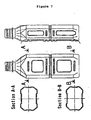
- the flat container of the present invention is a container whose section has preferably a flat shape, such as a rectangle and an ellipse, with the exception of the mouth opening. Appearance views and sectional views, such as front views, side views and views with arrows, in flat containers are shown in Figures 3(a) to 3(c) and Figures 4(a) to 4(c) .
- beverage bottles formed from the flat container of the present invention can be easily held by consumers with hand and fingers, are not slippery even when the container surfaces are wet while in use, and are beautiful thanks to complex shapes.
- the specified flat container of the present invention is manufactured by blow molding a bottomed parison preformed from a polyester resin.
- the inventors of the present application devised the inventions relating to a blow molding method of a flat container in order to manufacture a flat container which has a uniformly formed wall thickness and is excellent in mechanical strength and thermal resistance and which shape is stable even at high temperatures, and they filed applications for these inventions. Therefore, in the molding of the flat container of the present invention, in particular in the above-described inventions [1] and [2], it is possible to use the blow molding method relating to the prior inventions in manufacturing a desired flat container, in which molding is performed with a uniform wall thickness of the container wall, as the above-described invention [8].
- a preformed bottomed parison having a uniform wall thickness in transverse section and a roughly circular section is subjected to primary blow molding and stretched into a bottomed parison having a diameter larger than the minor axis of a mold for secondary blow molding (corresponding to the minor axis of a flat container), and this bottomed parison is caused to shrink in a heated condition to cause the bottomed parison to maintain a diameter which is smaller than the major axis of the cavity within the mold for secondary blow molding.
- a mold having a cavity of the sectional shape of the flat container, which is a molded article, is prepared, this bottomed, stretched parison is housed in a cavity for secondary blow molding, and mold clamping is performed, with the bottomed, stretched parison depressed into flat condition in the minor axis direction of the cavity to perform the secondary blow molding.
- the bottomed, stretched parison is housed in such a manner that the section of the bottomed, stretched parison becomes longer on the major axis side of the cavity than on the minor axis side of the cavity, and the bottomed, stretched parison is depressed and deformed in a flat condition.
- the mold In the primary blowing of the bottomed parison, the mold is used to stabilize the shape after blowing. However, from an economical aspect, free blowing in which a mold is not used may also be performed.
- the mold temperature in primary blowing is on the order of 150°C and cooling is performed by air cooling in free blowing.
- the two-stage blowing process of biaxial stretching is desirable in order to improve the physical properties of molded articles.
- the mouth opening of a container is not stretched and, therefore, strength and heat resistance are improved by separately performing crystallization under heat.
- the specified flat container of the present invention is advantageously manufactured by the blow molding of a bottomed parison preformed from a polyester resin by methods as described above. Properties such as the flatness ratio and wall thickness ratio described below are imparted to the flat container by setting molding conditions and the like and by appropriate designing as in each embodiment, which will be described later.
- the flatness ratio is the ratio of the major axis to the minor axis (both being an outside diameter) of the body section of a container, which shows flatness, and provides an index of the flatness of the body section of a container.
- the flatness ratio is expressed by the ratio of the major axis (6, 106) to the minor axis (7, 107) in the horizontal section (B-B, D-D) of the body (2, 102) of a container (1, 101).
- the reference numerals 1 and 101 denote a flat polyester resin container
- the reference numerals 2 and 102 denote a container body
- the reference numerals 3 and 103 denote a container bottom
- the reference numerals 4 and 104 denote a container neck
- the reference numerals 5 and 105 denote a container shoulder
- the reference numerals 6 and 106 denote the major axis of the container body
- the reference numerals 7 and 107 denote the minor axis of the container body
- the reference numerals 8 and 108 denote a container mouth opening
- the reference numeral 9 denotes a sampling position for the measurement of a maximally stretched portion (a column part)
- the reference numeral 10 denotes a sampling position for the measurement of a minimally stretched portion (the middle part of a panel).
- the flatness ratio along with the wall thickness ratio etc. of the container body is deeply associated with the mechanical strength, heat resistance, etc. of a flat container in association with the extensibility in the container body at high temperatures, the thermal no-load change of the container body at high temperatures, the crystallinity of the container body, etc. Therefore, from the experiment data (shown in Table 1, which will be described later) it is necessary that the flatness ratio be not less than 1.3, and this specification of the numerical value ensures that beverage bottles are easily held by consumers with hand and fingers and are beautiful because of their complex shapes.
- the wall thickness ratio of the container body is an index indicative of the uniformity of the wall thickness of the whole container body. The closer to the numerical value of 1, the more the wall thickness will be uniform as a whole, and this is desirable.
- the wall thickness ratio is expressed as the ratio of a maximum wall thickness to a minimum wall thickness of the section of the container body except the container neck and the part in contact with the ground.
- the wall thickness ratio is deeply associated with the mechanical strength, heat resistance, etc. of a flat container, in association with the extensibility in the container body at high temperatures, the thermal no-load change of the container body at high temperatures, the crystallinity of the container body, etc. Therefore, from the experiment data (shown in Table 1, which will be described later) it is necessary that the wall thickness ratio be not more than 1.6.
- the difference in elongation at high temperatures is deeply associated with the mechanical strength, heat resistance, etc. of a flat container. Therefore, concretely, a difference in elongation between a maximally stretched portion (a column part) and a minimally stretched portion (the middle part of a panel) of the container body in a tensile test at 95°C is adopted as the difference in elongation at high temperatures.
- the difference in elongation at high temperatures is illustrated as a graph in Figure 5 , and calculated by an experiment method, which will be described later. From the experiment data (shown in Table 1, which will be described later) it is necessary that the difference in elongation at high temperatures be not more than 150%.
- the shape of a container is stable even when the contents of the container are filled at temperatures of the order of 95°C, and the shape is not distorted by deformation unlike conventional flat containers.
- Crystallinity is an index (unit: %) indicative of the crystallizability of the body of a flat container. Crystallinity along with the flatness ratio etc. is deeply associated with the mechanical strength, heat resistance, etc. of a flat container. Therefore, from the.experiment data (shown in Table 1, which will be described later) it is necessary that crystallinity be not less than 30%.
- Crystallinity is a numerical value particularly indispensable for the improvement of the heat resistance of a container and calculated by an experiment calculating formula, which will be described later.
- the difference in TMA no-load change indicates the evaluation of heat resistance, in particular.
- the difference in TMA no-load change is not more than 500 ⁇ m, the shape of a container is stable even when the contents of the container are filled at temperatures of the order of 95°C, and the shape is not distorted by deformation unlike conventional flat containers.
- a maximally stretched portion and a minimally stretched portion of the container body exhibit different magnifications of elongation and amounts of secondary working and hence the column part and panel part have different heat resistance values. Therefore, when the contents are filled at high temperatures, the panel part bulges and heat resistance tends to become poor.
- the flat container of the present invention that meets this requirement has a small difference in orientation condition between a maximally stretched portion and a minimally stretched portion compared to conventional flat containers and is excellent in heat resistance and hence the panel part does not bulge even when the contents are filled at high temperatures.
- Molding resin materials for flatness containers are polyester resins. Although polylactate resin and the like can be mentioned as examples, usual polyethylene terephthalate (PET) is mainly used in consideration of mechanical strength and heat resistance.
- PET polyethylene terephthalate
- the main repetition unit is ethylene terephthalate and it is desirable to use a crystalline resin in which not less than 90 mol% of the acid constituents is terephthalic acid and not less than 90 mol% of the glycol constituents is ethylene glycol.
- Isophthalic acid, naphthalene dicarboxylic acid, etc. can be mentioned as examples of other acid constituents of this PET, and diethylene glycol, 1,4-butanediol, cyclohexane dimethanol, propylene glycol, etc. can be mentioned as examples of other glycol constituents.
- an oxygen-absorbing or oxygen- blocking functional resin with the resin constituting a container. Furthermore, according to the use, in order to impart other performance, it is possible to appropriately blend various kinds of additives, such as a usual coloring agent, ultraviolet absorbing agent, antioxidant, antibacterial agent and oxygen absorbing agent.
- the present invention also covers a flat thermoplastic resin container characterized by comprising a multilayer structure of a polyester resin layer and a functional thermoplastic resin layer.
- a laminated, bottomed parison which is a multilayer material, can be appropriately used, and the oxygen blocking properties are improved by the laminating with, for example, polyamide and EVAL.
- the oxygen absorbing properties may also be improved by providing an oxygen absorbing layer in the intermediate layer.
- a polymer induced from polyene is desirable as an oxidizable material used in the oxygen absorbing layer. Resins containing units induced from polyenes containing 4 to 20 carbon atoms or pen chain or cyclic conjugated or nonconjugated polyenes are advantageously used as such polyene.
- transverse ribs of concavities on the long-side side surface of a flat container, and particularly one or more transverse ribs of concavities that are horizontal as viewed from the height of the container.
- the mechanical strength, heat resistance, etc. are improved more by the ribs.
- the ribs can be formed by a molding process which will be described later in 3.(2).
- the flat container of the present invention can be manufactured by the following basic molding method and improved molding method as two-stage biaxial stretching blow molding.
- FIG. 2(a) to 2(d) the basic steps of the two-stage blow molding process are shown as schematic diagrams in Figures 2(a) to 2(d) .
- This is a manufacturing method of a flat container by the two-stage blow molding process comprising the steps (a) to (d): (a) subjecting a bottomed parison (a first intermediate molded article) 22 preformed from a polyester resin to primary blow molding, thereby molding the bottomed parison into a bottomed cylindrical body (a second intermediate molded article) having a diameter larger than the minor axis of a cavity within a mold for secondary blow molding, (b) causing thereafter the bottomed cylindrical body to shrink in a heated condition, thereby to cause the bottomed cylindrical body to maintain a diameter which is smaller than the major axis of the cavity within the mold for secondary blow molding and larger than the minor axis thereof, (c) attaching the bottomed cylindrical molded article (a third intermediate molded article) to the interior of the mold for secondary blow molding
- the step (a) involves subjecting a bottomed parison having a section of a roughly circular shape preformed from a thermoplastic resin to primary blow molding, thereby molding the bottomed parison into a bottomed cylindrical body having a section of a roughly circular shape and a diameter larger than the minor axis of a cavity within a mold for secondary blow molding.
- the parison is formed by usual means, such as an injection molding machine and an extrusion molding machine, and thermoplastic polyethylene terephthalate (PET) is used as the material.
- PET thermoplastic polyethylene terephthalate
- any resin such as polyethylene, polypropylene and polycarbonate may also be used.
- a bottomed parison having a section of a roughly circular shape is desirable from the standpoints of production efficiency and blow efficiency, and the size of the parison is appropriately set according to the size of a desired flat container, secondary blow efficiency, etc.
- the primary blowing of a parison a mold is used to stabilize the shape after blowing.
- the primary blowing may be performed by free blowing in which a mold is not used.
- the mold temperature in primary blowing is on the order of 150°C and cooling is performed by air cooling in free blowing.
- the step (b) involves causing the bottomed cylindrical body to shrink in a heated condition.
- the bottomed parison is molded into a bottomed cylindrical body (an intermediate molded article) having a section of a roughly circular shape and a diameter which is larger than the minor axis of the cavity within the mold for secondary blow molding
- the bottomed cylindrical body is caused to shrink under heat in an oven, whereby residual strains generated in the resin by the primary blow molding are relieved and the bottomed cylindrical body is caused to maintain a diameter which is smaller than the major axis of the cavity within the mold for secondary blow molding and larger than the minor axis thereof.
- PET heating conditions which are such that the bottle temperature behind the oven is not less than 150°C are adopted. Crystallization and thermal fixing are homogeneously and sufficiently performed by this step and the parison that has been stretched and inflated by primary blowing is caused to shrink and is reduced in diameter.
- the size of the section diameter of the intermediate molded article after thermal shrinkage is an important requirement to be considered when the intermediate molded article is housed (attached) in the mold for secondary blowing by being depressed in a flat shape.
- this size is set in such a manner that a gap for the stretching of the intermediate molded article is maintained between the intermediate molded article which has been stretched by the deformation due to depression on the major axis side and the inner surface of the mold.
- the size of the section diameter of the intermediate molded article be on the order of 1.1 to twice the minor axis of the cavity of the secondary blow mold.
- the step (c) involves attaching the intermediate molded article to the interior of the mold for secondary blow molding, and performing mold clamping, with the intermediate molded article depressed in the minor axis direction of the cavity within the mold.
- the step (d) involves feeding a pressure fluid into the bottomed cylindrical molded article, and causing the intermediate molded article to flow in a heated condition along the shape of the cavity on an inner surface of the mold, thereby to mold the flat container.
- the step corresponds to secondary blowing in the two-stage blow molding to mold by blowing the intermediate molded article to a final shape of the flat container.
- a split mold be used as the mold for secondary blow molding, and for the sake of convenience, it is preferred that heated air be used as the pressure liquid.
- the blowing air pressure is on the order of 2 to 4 MPa, which are usual values.
- the mold surface treatment examples include surface roughening treatment and coating treatment.
- surface roughening treatment for example, the mold surface may be roughened by being rubbed with sandpaper, water-resistant paper and the like, or the mold surface may be roughened by sandblasting treatment and iepco treatment (a surface treatment method which involves performing peening with ultrafine hard balls after the removal of burrs from the surface to be treated and cleaning thereof.
- coating treatment examples include coating with silicon, tungsten disulfide, fluororesin, etc.
- coating with fluororesin is desirable from the standpoints of the slipperiness between a third intermediate molded article and the mold in the blow molding of the third intermediate molded article and of the durability of a coating agent.
- a tetrafluoroethylene perfluoroalky vinyl ether copolymer (PFA) and polytetrafluoroethylene (PTFE) are preferably be used.
- the lateral width thereof be 30 to 90% of the major axis of a mold cavity surface, that the longitudinal width thereof (the width equivalent to the vertical height of a container) is 1 to 30% of the formed height of a flat product on the mold cavity surface, and that the height thereof is 2 to 40% of the minor axis of the mold cavity surface. It is because the waviness of concavities which partially occurs on the major axis side surface of an intermediate molded article is absorbed in the convexities.
- the surface area of the convexities increases and it becomes easier to absorb the waviness of the concavities in an intermediate molded article.
- the concavities on the container surface may be made deep stepwise and may also be provided in a pressure-reducing absorption panel.
- the formation of convexities on the mold surface is also illustrated as indicated by the hatched area.
- Crystallinity % ⁇ c ⁇ ⁇ - ⁇ a / ⁇ ⁇ ⁇ c - ⁇ a ⁇ 100
- a strip-like test piece having a size 5 ⁇ 40 mm is cut out in the longitudinal (height) direction each in the maximally stretched portion (a column part) 9 and a minimally stretched portion (the middle part of a panel) 10 at the same level of the.body of a flat container, and the test pieces are subjected to a tensile test in a thermoregulator at 95°C.
- a difference in a maximum elongation between the two places is regarded as the difference in elongation by stretching at 95°C.
- Figure 5 illustrates a graph that shows measurement results of a difference in elongation in the tensile test at 95°C.
- a strip-like test piece having a size 5 ⁇ 40 mm is cut out in the longitudinal (height) direction each in the maximally stretched portion (a column part) 9 and a minimally stretched portion (the middle part of a panel) 10 at the same level of the body of a flat container, and the test pieces are measured by TMA (a thermomechanical analysis) method.
- TMA thermomechanical analysis
- Hot water at 87°C was filled in a flat container, the flat container was showered with warm water at 75°C for five minutes after hermetical sealing, and the container was visually checked for deformation. ( ⁇ : without deformation, ⁇ : with deformation)
- a bottomed parison which was a first intermediate molded article having an outside diameter of 22 mm, a thickness of 3.4 mm and a height of 80 mm, was preformed from commercially available polyethylene terephthalate (PET), heated air was blown in by free blowing and the first intermediate molded article was subjected to primary blow molding to form a second intermediate molded article having an outside diameter of 90 mm.
- PET polyethylene terephthalate
- the second intermediate molded article subjected to the primary blow molding was caused to shrink and be fixed for 8 seconds in an oven at 600°C and a shrunk, molded article having an outside diameter of 60 mm, which was a third intermediate molded article, was obtained.
- a mold for second blow molding (set at 140°C) had a cavity (section: minor axis 50 m, major axis 66 mm) with the rectangular section shown in (d) of Figure 2 , and an upper portion of a body molding surface of the blow mold on the long-side side of a container was coated with a fluororesin.
- the third intermediate molded article was housed in the cavity by being depressed into the cavity in the minor axis direction.
- Air at 20°C and 3 MPa was fed into the third intermediate molded article deformed by depression and secondary blow molding was performed, whereby a flat container having a rectangular section and a flatness ratio of 1.3 was molded. No wrinkle remained in the body of this flat container.
- Table 1 shows measurement results of the crystallinity of the body of this flat container, the wall thickness ratio of a maximum wall thickness to a minimum wall thickness of the section of the container, the difference in elongation between a maximally stretched portion and a minimally stretched portion of the container body in a tensile test at 95°C, and the difference in TMA no-load change in a maximally stretched portion and a minimally stretched portion of the container body in the range from 75°C to 100°C.
- a flat container having an elliptical section and a flatness ratio of 1.5 was molded in the same way as in Embodiment 1, with the exception that primary blow molding was performed by using a mold for primary blow molding instead of performing free blow molding and that a mold which upper portion of a body molding surface thereof on the long-side side (major axis side) of a container was coated with a fluororesin and which had a cavity (section: minor axis 47 mm, major axis 70 mm) with an elliptical section was used as a second blow mold.
- a flat container having a rectangular section and a flatness ratio of 2.0 was molded in the same way as in Embodiment 1, with the exception that primary blow molding was performed by using a mold for primary blow molding instead of performing free blow molding and that a mold which upper.portion of a body molding surface thereof on the long-side side of a container was coated with a fluororesin and which had a cavity (section: minor axis 40 mm, major axis 80 mm) with a rectangular section was used as a second blow mold.
- a flat container having a rectangular section and a flatness ratio of 2.5 was molded in the same way as in Embodiment 1, with the exception that primary blow molding was performed by using a mold for primary blow molding instead of performing free blow molding and that a mold which upper portion of a body molding surface thereof on the long-side side of a container was coated with a fluororesin and which had a cavity (section: minor axis 36 mm, major axis 90 mm) with a rectangular section was used as a second blow mold.
- a flat container having a rectangular section and a flatness ratio of 2.0 was molded in the same way as in Embodiment 3, with the exception that a mold which lower portion of a body folding surface thereof on the long-side side of a container was coated with a fluororesin and which had a cavity (section: minor axis 40 mm, major axis 80 mm) with a rectangular section was used as a second blow mold.
- a flat container having a rectangular section and a flatness ratio of 2.0 was molded in the same way as in Embodiment 3, with the exception that a mold which had convexities in an upper portion of a body molding surface thereof on the long-side side of a container and had a cavity (section: minor axis 40 mm, major axis 80 mm) with a rectangular section was used as a second blow mold.
- a flat container having a rectangular section and a flatness ratio of 2.0 was molded in the same way as in Embodiment 3, with the exception that a mold which had convexities in a lower portion of a body molding surface thereof on the long-side side of a container and had a cavity (section: minor axis 40 mm, major axis 80 mm) with a rectangular section was used as a second blow mold.
- a flat container having a rectangular section and a flatness ratio of 2.0 was molded in the same way as in Embodiment 3, with the exception that a mold which had convexities in an upper portion and a lower portion of a body molding surface thereof on the long-side side of a container and in which the whole area of a container molding surface was coated with a fluororesin, and which had a cavity (section: minor axis 40 mm, major axis 80 mm) with a rectangular section was used as a second blow mold.
- the flat containers molded in Embodiments 2 to 8 were product containers having no wrinkle in the body and a good appearance.
- Table 1 shows measurement results of the crystallinity of the bodies of these flat containers, the wall thickness ratio of a maximum wall thickness to a minimum wall thickness of the sections of the containers, the difference in elongation between a maximally stretched portion and a minimally stretched portion of the container bodies in a tensile test at 95°C, and the difference in TMA no-load change in a maximally stretched portion and a minimally stretched portion of the container bodies in the range from 75°C to 100°C.
- a flat container having a rectangular section and a flatness ratio of 1.3 was molded by using the same preformed parison as used in Embodiment 1, stretching the preformed parison by use of a mold for primary blow molding, housing a shrunk, intermediate molded article in the mold with a size not depressed in the minor axis direction, using the same mold for secondary blowing molding as used in Embodiment 1, and performing blow molding under the same blowing conditions.
- a flat container having a rectangular section and a flatness ratio of 2.0 was molded by using the same preformed parison as used in Embodiment 1, stretching the preformed parison by use of a mold for primary blow molding, housing a shrunk, intermediate molded article in the mold with a size not depressed in the minor axis direction, using the same mold for secondary blowing molding as used in Embodiment 3, and performing blow molding under the same blowing conditions.
- a flat container having a rectangular section and a flatness ratio of 2.0 was molded in the same way as in Embodiment 3, with the exception that a mold in which the whole area of a container molding surface was subjected to mirror finish treatment and which had a cavity (section: minor axis 40 mm, major axis 80 mm) with a rectangular section was used as a mold for secondary blowing.
- a mold in which the whole area of a container molding surface was subjected to mirror finish treatment and which had a cavity (section: minor axis 40 mm, major axis 80 mm) with a rectangular section was used as a mold for secondary blowing.
- wrinkles remained in an upper portion and a lower portion of the body on the long-side side and the shape was poor.
- Table 1 shows measurement results of the crystallinity of the bodies of the flat containers molded in Comparative Examples 1 to 3, the wall thickness ratio of a maximum wall thickness to a minimum wall thickness of the sections of the containers, the difference in elongation between a maximally stretched portion and a minimally stretched portion of the container bodies in a tensile test at 95°C, and the difference in TMA no-load change in a maximally stretched portion and a minimally stretched portion of the container bodies in the range from 75°C to 100°C.
- a flat container in the present invention is excellent in heat resistance and mechanical strength if it meets the requirements for the flatness ratio, the wall thickness ratio, crystallinity, the difference in elongation in a tensile test at 95°C, and the TMA difference. Furthermore, it has become obvious that a poor appearance, such as wrinkles, does not occur any more by performing two-stage blow molding that involves secondary blow molding after a third intermediate molded article is depressed by use of a secondary blowing mold which is subjected to coating with a fluororesin or in which convexities are formed.
- Embodiments 1 to 8 as is apparent from the numerical figures shown in Table 1, the circumferential wall thickness ratio of the body of each container was small with high uniformity of the wall thickness and the difference in physical properties in a maximally stretched portion and a minimally stretched portion of the container body was small. Therefore, the mechanical strength was sufficient and the heat resistance was also good.
- the difference in elongation between a maximally stretched portion and a minimally stretched portion at high temperatures was small compared to the comparative examples and also the difference in TMA no-load change was also small compared to the comparative examples. Therefore, even when the contents are filled at high temperatures, the shape is stable and the shape is not distorted by deformation unlike conventional flat containers.
- Comparative Examples 1 and 2 a shrunk, intermediate molded article is housed in the mold with a size not depressed in the minor axis direction. Therefore, as is apparent from the numerical values shown in Table 1, the circumferential wall thickness ratio of the container body was large compared to each of the embodiments. Thus Comparative Examples 1 and 2 were inferior to each of the embodiments in the uniformity of the wall thickness. Also the difference in elongation between a maximally stretched portion and a minimally stretched portion at high temperatures and the difference in TMA no-load change were large compared to each of the embodiments. Thus Comparative Examples 1 and 2 were inferior to each of the embodiments in heat resistance and mechanical strength.
- Comparative Example 3 a shrunk, intermediate molded article is housed in the mold by being depressed in the minor axis direction.
- Comparative Example 3 is excellent in the circumferential wall thickness ratio of the container body, the difference in elongation in a maximally stretched portion and a minimally stretched portion at high temperatures, and the difference in TMA no-load change to the same extent as each of the embodiments.
- the shapability (moldability) of secondary blow molding is poor and the heat resistance was so poor that it could not be evaluated.
- the flat container in the present invention is excellent in mechanical strength and heat resistance, the shape of the container is stable even at high temperatures, and there is no fear that the container might be deformed because of insufficient resistance against inner pressure loads due to the expansion of beverages in the container at high temperatures and against external pressure loads due to the shrinkage of the interior during temperature drops.
- this flat container is particularly excellent as containers for high-temperature beverages and containers for high-temperature pasteurized beverages, and is also advantageously used for food in general, medical products, etc.
- the present invention enables excellent containers used in various technical fields to be developed, is useful in the industries of plastic molding and plastic containers, and has high industrial applicability.
Landscapes
- Engineering & Computer Science (AREA)
- Mechanical Engineering (AREA)
- Manufacturing & Machinery (AREA)
- Ceramic Engineering (AREA)
- Blow-Moulding Or Thermoforming Of Plastics Or The Like (AREA)
- Containers Having Bodies Formed In One Piece (AREA)
- Processing And Handling Of Plastics And Other Materials For Molding In General (AREA)
- Injection Moulding Of Plastics Or The Like (AREA)
Abstract
Description
- The present invention relates to a flat container made of a thermoplastic resin and, more particularly, to a flat container whose section is an ellipse or a rectangle or has other shapes, the body of which has a uniformly formed wall thickness, and which has high thermal resistance and is not deformed at high temperatures and a method for molding the flat container.
- Thanks to their excellent mechanical strength, moldability, transparency, recyclability of resources, etc. polyester resin containers, such as PET bottles, have been recognized as containers for food and drink and they have been in great demand. In particular, recently polyester resin containers have been habitually used by consumers as portable small containers for beverage use. The heat resistance and pressure resistance of such small containers for beverage use have been remarkably improved by the development of the two-stage blow molding process (refer to Japanese Patent Publication No.
4-56734 claim 1 and the upper section of the left column on page 2)) and small containers have become capable of being used for high-temperature beverages and beverages requiring high-temperature pasteurization. Thus, they have become able to meet consumers' strong requests for portable high-temperature beverages for the winter season in daily life. - Furthermore, reuse systems of PET bottles have been established to meet the social requests for resource savings and environmental protection, and the cleanliness due to the transparency of containers and the sense of safety by seeing the beverages inside through containers meet consumers' cleanliness-oriented trends, with the result that the demand for polyester resin containers represented by PET bottles has been increasing further.
- Recent consumers prefer beverage bottles of flat shape having a rectangular section etc. because these bottles are easy to hold and beautiful thanks to their complex shapes, whereas bottles having a circular section tend to be avoided because they are difficult to grip due to slipperiness when their surfaces become wet and because they lack aesthetic impressions due to the simple shape of a circle.
- Flat containers having flat shapes with rectangular, elliptical or other sections that tend to be liked by consumers and have a very strong demand are manufactured by blow molding (molding by blowing the air), with a preformed, bottomed parison (a preform) inserted into the interior of a mold having a flat section and attached thereto. On the occasion of molding into a flat shape, the wall thickness of a container wall tends to become nonuniform due to a difference in the amount of elongation in the major axis direction and minor axis direction of the section of the container and for other reasons.
- As a measure to prevent this, there is known, for example a method for obtaining a flat container that involves inflating a bottomed parison having a circular section in a first blow mold into an intermediate molded article, inserting this intermediate molded article into a second blow mold, flattening the intermediate molded article into an elliptical shape by mold closing, and performing thereafter blow molding (refer to Japanese Patent Publication No.
59-53861 Figure 1 )). In this method, however, the shapability by blow molding-is insufficient and wrinkles due to the waviness of concavities occurring partially on the surface of an intermediate molded article are apt to remain on the surface of a product, posing the problems of a poor appearance and insufficient strength. - In addition, some methods and apparatus for aiming at a uniform wall thickness in the manufacture of a flat container by blow molding have been disclosed. They are, for example, a bottomed cold parison blow molding process, which involves heating a bottomed cold parison before blow molding so that a portion stretched in the minor axis direction of a flat shape obtains a higher temperature than a portion stretched in a major axis direction or using a bottomed parison that is formed with thickness uniformity so that the wall thickness of a portion stretched in the major axis direction becomes large and the wall thickness of a portion stretched in the minor axis direction becomes small, and radiant heating the bottomed parison in its periphery while rotating the bottomed parison in the axial direction (refer to Japanese Patent Laid-Open No.
2000-127230 8-294958 - When the wall thickness becomes nonuniform, the mechanical strength and heat resistance of a container decrease due to thin-walled portions. When such containers are used as high-temperature beverage containers, there is a fear that the deformation of the containers may occur because they cannot withstand inner pressure loads due to the expansion of beverages in the containers at high temperatures and external pressure loads due to the shrinkage of the interior during temperature drops.
- On the other hand, in a flat container obtained by blow molding, from viewpoints different from the intension improve the blow molding process, there has scarcely been made any proposal as yet to make improvements on mechanical strength, heat resistance, etc. specific to flat containers by specifying flat containers by physical properties and imparting characteristics to flat containers and to prevent the fear that the deformation of the containers may occur because they cannot withstand inner pressure loads due to the expansion of beverages in the containers at high temperatures and external pressure loads due to the shrinkage of the interior during temperature drops, and under the present circumstance, there is only a proposal which is such that a polyolefin-based flat container obtained by injection blow molding in which only the flatness ratio (the maximum major axis of the body/the minimum minor axis of the body) and wall thickness are specified is shown (refer to Japanese Patent Laid-Open No.
11-170344 - Japanese Patent Application No.
53067279 - In view of the condition of such conventional techniques in flat thermoplastic resin containers such as polyester resin containers obtained by blow molding, which are liked by consumers as beverage plastic containers and their demand is especially increasing because they are easy to carry and beautiful thanks to complex shapes, the present inventors consider that the first problem to be solved by the invention is to realize a flat container excellent in mechanical properties and heat resistance by specifying flat containers by physical properties and imparting characteristics to flat containers and improving mechanical strength, heat resistance, etc. specific to flat containers. At the same time, in the manufacture of a plastic flat container for beverage having a flat sectional shape, such as a rectangle by blow molding, from the standpoint of a molding method of such a flat container, the present inventors consider that the second problem to be solved by the invention is to realize a molding method for easily manufacturing a flat container with an improved uniformity of wall thickness, with improved mechanical strength, heat resistance, etc. and with a good appearance without a wrinkle.
- Aiming at solving the above-described first problem in flat containers made of a thermoplastic resin in order to clearly materialize a flat container excellent in mechanical strength, heat resistance, etc. by a uniform wall thickness of the container wall and the like, the present inventors investigated the specification and impartment of characteristics in flat containers in which blow molding is used, considered techniques for giving a concrete form to them from various view points of physical properties and a structure of a container, and made trials. Through these processes, the present inventors could discover that the ratio of the major axis to the minor axis (flatness ratio) of a body section of a container, which expresses flatness, the wall thickness ratio of a container body, which is an index indicative of the uniformity of the whole container body, etc. relate to the extensibility in the container body at high temperatures, thermal no-load changes of the container body at high temperatures, the crystallinity of the container body, etc., and are deeply related to the mechanical strength, heat resistance, etc. of flat containers while having correlations to each other. And as a result of this, the present inventors finally reached the creation of a novel flat container as the first basic invention in the present application by specifying these correlations as numerical values.
- Concretely, the above-described flatness ratio and wall thickness ratio are specified by experimentally selecting the flatness ratio and wall thickness ratio, a difference in elongation between a maximally stretched portion and a minimally stretched portion of the container body in a tensile test at 95°C is adopted as the specification of extensibility in the container body at high temperatures, a difference in TMA non-load change between a maximally stretched portion and a minimally stretched portion in the range of 75°C to 100°C is selected as the specification of a thermal no-load change of the container body at high temperatures, and these relationships are correlated with each other, whereby it has become possible to clearly give a concrete form to a flat polyester resin container excellent in mechanical properties, heat resistance, etc. and to materialize the flat polyester resin container.
- Embodiments of the above-described invention will be concretely described in detail with reference to the drawings.
- The flat container of the present invention is a container which is specified by various kinds of physical properties and to which characteristics are imparted, as will be described in detail below. As shown in
Figures 3(a) to 3(c) andFigures 4(a) to 4(c) , the flat container of the present invention is a container whose section has preferably a flat shape, such as a rectangle and an ellipse, with the exception of the mouth opening. Appearance views and sectional views, such as front views, side views and views with arrows, in flat containers are shown inFigures 3(a) to 3(c) andFigures 4(a) to 4(c) . - Because of the flat shapes, beverage bottles formed from the flat container of the present invention can be easily held by consumers with hand and fingers, are not slippery even when the container surfaces are wet while in use, and are beautiful thanks to complex shapes.
- The specified flat container of the present invention is manufactured by blow molding a bottomed parison preformed from a polyester resin.
- Incidentally, as described above, prior to the creation of the present invention, the inventors of the present application devised the inventions relating to a blow molding method of a flat container in order to manufacture a flat container which has a uniformly formed wall thickness and is excellent in mechanical strength and thermal resistance and which shape is stable even at high temperatures, and they filed applications for these inventions. Therefore, in the molding of the flat container of the present invention, in particular in the above-described inventions [1] and [2], it is possible to use the blow molding method relating to the prior inventions in manufacturing a desired flat container, in which molding is performed with a uniform wall thickness of the container wall, as the above-described invention [8].
- Concretely, as shown in
Figures 2(a) to 2(d) as step drawings, a preformed bottomed parison having a uniform wall thickness in transverse section and a roughly circular section is subjected to primary blow molding and stretched into a bottomed parison having a diameter larger than the minor axis of a mold for secondary blow molding (corresponding to the minor axis of a flat container), and this bottomed parison is caused to shrink in a heated condition to cause the bottomed parison to maintain a diameter which is smaller than the major axis of the cavity within the mold for secondary blow molding. On the other hand, a mold having a cavity of the sectional shape of the flat container, which is a molded article, is prepared, this bottomed, stretched parison is housed in a cavity for secondary blow molding, and mold clamping is performed, with the bottomed, stretched parison depressed into flat condition in the minor axis direction of the cavity to perform the secondary blow molding. As a result, the bottomed, stretched parison is housed in such a manner that the section of the bottomed, stretched parison becomes longer on the major axis side of the cavity than on the minor axis side of the cavity, and the bottomed, stretched parison is depressed and deformed in a flat condition. And when secondary blow molding is performed, the wall thickness on the minor axis side and major axis side of the formed flat container becomes uniform or sufficiently uniform. As a result of this, two-stage blowing of biaxial stretching is performed and this enables the stretching and crystallization of the bottomed parison to be sufficiently carried out and yields the subsidiary action that the heat resistance and pressure resistance of a flat container are remarkably improved. - In the primary blowing of the bottomed parison, the mold is used to stabilize the shape after blowing. However, from an economical aspect, free blowing in which a mold is not used may also be performed.
- It is possible to raise the magnification of transverse elongation up to 3 to 5 times and the magnification of longitudinal elongation up to 2 to 4 times in the primary blowing and this brings about the high orientation of crystals and the homogenization of elongation. It is also possible to suppress the magnification of elongation on the minor axis side (the minor axis of the container/the center diameter of the preform) to the order of 2.5 times. In PET, the mold temperature in primary blowing is on the order of 150°C and cooling is performed by air cooling in free blowing. As the blow molding, the two-stage blowing process of biaxial stretching is desirable in order to improve the physical properties of molded articles.
- Incidentally, in general, the mouth opening of a container is not stretched and, therefore, strength and heat resistance are improved by separately performing crystallization under heat.
- The specified flat container of the present invention is advantageously manufactured by the blow molding of a bottomed parison preformed from a polyester resin by methods as described above. Properties such as the flatness ratio and wall thickness ratio described below are imparted to the flat container by setting molding conditions and the like and by appropriate designing as in each embodiment, which will be described later.
- The flatness ratio is the ratio of the major axis to the minor axis (both being an outside diameter) of the body section of a container, which shows flatness, and provides an index of the flatness of the body section of a container. Concretely, in the containers having a flat shape shown in
Figures 3(a) to 3(c) andFigures 4(a) to 4(c) , the flatness ratio is expressed by the ratio of the major axis (6, 106) to the minor axis (7, 107) in the horizontal section (B-B, D-D) of the body (2, 102) of a container (1, 101). Incidentally, inFigures 3(a) to 3(c) andFigures 4(a) to 4(c) , thereference numerals reference numerals reference numerals reference numerals reference numerals reference numerals reference numerals reference numerals reference numeral 9 denotes a sampling position for the measurement of a maximally stretched portion (a column part), and thereference numeral 10 denotes a sampling position for the measurement of a minimally stretched portion (the middle part of a panel). - In the present invention, the flatness ratio along with the wall thickness ratio etc. of the container body is deeply associated with the mechanical strength, heat resistance, etc. of a flat container in association with the extensibility in the container body at high temperatures, the thermal no-load change of the container body at high temperatures, the crystallinity of the container body, etc. Therefore, from the experiment data (shown in Table 1, which will be described later) it is necessary that the flatness ratio be not less than 1.3, and this specification of the numerical value ensures that beverage bottles are easily held by consumers with hand and fingers and are beautiful because of their complex shapes.
- The wall thickness ratio of the container body is an index indicative of the uniformity of the wall thickness of the whole container body. The closer to the numerical value of 1, the more the wall thickness will be uniform as a whole, and this is desirable. The wall thickness ratio is expressed as the ratio of a maximum wall thickness to a minimum wall thickness of the section of the container body except the container neck and the part in contact with the ground.
- As with the flatness ratio, the wall thickness ratio is deeply associated with the mechanical strength, heat resistance, etc. of a flat container, in association with the extensibility in the container body at high temperatures, the thermal no-load change of the container body at high temperatures, the crystallinity of the container body, etc. Therefore, from the experiment data (shown in Table 1, which will be described later) it is necessary that the wall thickness ratio be not more than 1.6.
- The difference in elongation at high temperatures is deeply associated with the mechanical strength, heat resistance, etc. of a flat container. Therefore, concretely, a difference in elongation between a maximally stretched portion (a column part) and a minimally stretched portion (the middle part of a panel) of the container body in a tensile test at 95°C is adopted as the difference in elongation at high temperatures. The difference in elongation at high temperatures is illustrated as a graph in
Figure 5 , and calculated by an experiment method, which will be described later. From the experiment data (shown in Table 1, which will be described later) it is necessary that the difference in elongation at high temperatures be not more than 150%. - When the difference in elongation between a maximally stretched portion and a minimally stretched portion at high temperatures is not more than 150%, the shape of a container is stable even when the contents of the container are filled at temperatures of the order of 95°C, and the shape is not distorted by deformation unlike conventional flat containers.
- Crystallinity is an index (unit: %) indicative of the crystallizability of the body of a flat container. Crystallinity along with the flatness ratio etc. is deeply associated with the mechanical strength, heat resistance, etc. of a flat container. Therefore, from the.experiment data (shown in Table 1, which will be described later) it is necessary that crystallinity be not less than 30%.
- Crystallinity is a numerical value particularly indispensable for the improvement of the heat resistance of a container and calculated by an experiment calculating formula, which will be described later.
- The difference in no-load change of a flat container along with the difference in elongation at high temperatures is deeply associated with the mechanical strength, heat resistance, etc. of a flat container. Therefore, concretely, a difference in TMA (thermomechanical analysis) no-load change between a maximally stretched portion and a minimally stretched portion of the container body in the range from 75°C to 100°C is adopted as the difference in no-load change. The difference in no-load change is illustrated as a graph in
Figure 6 , and calculated by an experiment method, which will be described later. From the experiment data (shown in Table 1, which will be described later) it is necessary that the difference in no-load change be not more than 500 µm. - The difference in TMA no-load change indicates the evaluation of heat resistance, in particular. When the difference in TMA no-load change is not more than 500 µm, the shape of a container is stable even when the contents of the container are filled at temperatures of the order of 95°C, and the shape is not distorted by deformation unlike conventional flat containers.
- In a flat container, a maximally stretched portion and a minimally stretched portion of the container body exhibit different magnifications of elongation and amounts of secondary working and hence the column part and panel part have different heat resistance values. Therefore, when the contents are filled at high temperatures, the panel part bulges and heat resistance tends to become poor. The flat container of the present invention that meets this requirement has a small difference in orientation condition between a maximally stretched portion and a minimally stretched portion compared to conventional flat containers and is excellent in heat resistance and hence the panel part does not bulge even when the contents are filled at high temperatures.
- Molding resin materials for flatness containers are polyester resins. Although polylactate resin and the like can be mentioned as examples, usual polyethylene terephthalate (PET) is mainly used in consideration of mechanical strength and heat resistance.
- In polyethylene terephthalate, the main repetition unit is ethylene terephthalate and it is desirable to use a crystalline resin in which not less than 90 mol% of the acid constituents is terephthalic acid and not less than 90 mol% of the glycol constituents is ethylene glycol. Isophthalic acid, naphthalene dicarboxylic acid, etc. can be mentioned as examples of other acid constituents of this PET, and diethylene glycol, 1,4-butanediol, cyclohexane dimethanol, propylene glycol, etc. can be mentioned as examples of other glycol constituents.
- It is also possible to blend an oxygen-absorbing or oxygen- blocking functional resin with the resin constituting a container. Furthermore, according to the use, in order to impart other performance, it is possible to appropriately blend various kinds of additives, such as a usual coloring agent, ultraviolet absorbing agent, antioxidant, antibacterial agent and oxygen absorbing agent.
- The present invention also covers a flat thermoplastic resin container characterized by comprising a multilayer structure of a polyester resin layer and a functional thermoplastic resin layer. For this reason, in the present invention, a laminated, bottomed parison, which is a multilayer material, can be appropriately used, and the oxygen blocking properties are improved by the laminating with, for example, polyamide and EVAL. The oxygen absorbing properties may also be improved by providing an oxygen absorbing layer in the intermediate layer. A polymer induced from polyene is desirable as an oxidizable material used in the oxygen absorbing layer. Resins containing units induced from polyenes containing 4 to 20 carbon atoms or pen chain or cyclic conjugated or nonconjugated polyenes are advantageously used as such polyene.
- As one of the ways of specifying the present invention, as illustrated in
Figure 7 , it is also possible to provide one or more transverse ribs of concavities on the long-side side surface of a flat container, and particularly one or more transverse ribs of concavities that are horizontal as viewed from the height of the container. The mechanical strength, heat resistance, etc. are improved more by the ribs. The ribs can be formed by a molding process which will be described later in 3.(2). - The flat container of the present invention can be manufactured by the following basic molding method and improved molding method as two-stage biaxial stretching blow molding.
- As already described, the basic steps of the two-stage blow molding process are shown as schematic diagrams in
Figures 2(a) to 2(d) . This is a manufacturing method of a flat container by the two-stage blow molding process comprising the steps (a) to (d): (a) subjecting a bottomed parison (a first intermediate molded article) 22 preformed from a polyester resin to primary blow molding, thereby molding the bottomed parison into a bottomed cylindrical body (a second intermediate molded article) having a diameter larger than the minor axis of a cavity within a mold for secondary blow molding, (b) causing thereafter the bottomed cylindrical body to shrink in a heated condition, thereby to cause the bottomed cylindrical body to maintain a diameter which is smaller than the major axis of the cavity within the mold for secondary blow molding and larger than the minor axis thereof, (c) attaching the bottomed cylindrical molded article (a third intermediate molded article) to the interior of the mold forsecondary blow molding 20, and performing mold clamping, with the bottomed cylindrical moldedarticle 23 depressed (crushed)in the minor axis direction of the cavity 21 within the mold, (d) feeding thereafter a pressure fluid into the bottomed cylindrical molded article, and causing the bottomed cylindrical molded article to flow in a heated condition along the shape of the cavity on an inner surface of the mold, thereby to mold the flat container. - The step (a) involves subjecting a bottomed parison having a section of a roughly circular shape preformed from a thermoplastic resin to primary blow molding, thereby molding the bottomed parison into a bottomed cylindrical body having a section of a roughly circular shape and a diameter larger than the minor axis of a cavity within a mold for secondary blow molding.
- The parison is formed by usual means, such as an injection molding machine and an extrusion molding machine, and thermoplastic polyethylene terephthalate (PET) is used as the material. However, in addition, any resin such as polyethylene, polypropylene and polycarbonate may also be used. As the parison to be used, a bottomed parison having a section of a roughly circular shape is desirable from the standpoints of production efficiency and blow efficiency, and the size of the parison is appropriately set according to the size of a desired flat container, secondary blow efficiency, etc.
- In the primary blowing of a parison, a mold is used to stabilize the shape after blowing. However, from an economical aspect, the primary blowing may be performed by free blowing in which a mold is not used.
- It is possible to raise the magnification of transverse elongation up to 3 to 5 times and the magnification of longitudinal elongation up to 2 to 4 times in the primary blowing and this brings about high orientation of crystals and the homogenization of elongation. In PET, the mold temperature in primary blowing is on the order of 150°C and cooling is performed by air cooling in free blowing.
- The step (b) involves causing the bottomed cylindrical body to shrink in a heated condition. After the bottomed parison is molded into a bottomed cylindrical body (an intermediate molded article) having a section of a roughly circular shape and a diameter which is larger than the minor axis of the cavity within the mold for secondary blow molding, the bottomed cylindrical body is caused to shrink under heat in an oven, whereby residual strains generated in the resin by the primary blow molding are relieved and the bottomed cylindrical body is caused to maintain a diameter which is smaller than the major axis of the cavity within the mold for secondary blow molding and larger than the minor axis thereof.
- In PET, heating conditions which are such that the bottle temperature behind the oven is not less than 150°C are adopted. Crystallization and thermal fixing are homogeneously and sufficiently performed by this step and the parison that has been stretched and inflated by primary blowing is caused to shrink and is reduced in diameter.
- The size of the section diameter of the intermediate molded article after thermal shrinkage is an important requirement to be considered when the intermediate molded article is housed (attached) in the mold for secondary blowing by being depressed in a flat shape. In order to ensure that the stretching on the major axis side is sufficiently performed and that the wall thickness becomes uniform, this size is set in such a manner that a gap for the stretching of the intermediate molded article is maintained between the intermediate molded article which has been stretched by the deformation due to depression on the major axis side and the inner surface of the mold. Incidentally, in order to ensure a uniform wall thickness of a molded article, it is preferred that the size of the section diameter of the intermediate molded article be on the order of 1.1 to twice the minor axis of the cavity of the secondary blow mold.
- The step (c) involves attaching the intermediate molded article to the interior of the mold for secondary blow molding, and performing mold clamping, with the intermediate molded article depressed in the minor axis direction of the cavity within the mold. By ensuring that the intermediate molded articles is attached to the interior of the mold for secondary blow molding, that mold clamping is performed, with the intermediate molded article depressed in the minor axis direction of the cavity within the mold as viewed from the section thereof, and that the intermediate molded article is housed in the cavity beforehand in a flat condition, the intermediate molded article is housed in such a manner that the section of the intermediate molded article becomes longer on the major axis side of the cavity than on the minor axis side thereof and the intermediate molded article is deformed by depression into a flat shape so that a gap for the stretching of the intermediate molded article is maintained between the intermediate molded article which has been stretched by the deformation due to depression on the major axis side and the inner surface of the mold.
- The step (d) involves feeding a pressure fluid into the bottomed cylindrical molded article, and causing the intermediate molded article to flow in a heated condition along the shape of the cavity on an inner surface of the mold, thereby to mold the flat container. The step corresponds to secondary blowing in the two-stage blow molding to mold by blowing the intermediate molded article to a final shape of the flat container.
- It is preferred that a split mold be used as the mold for secondary blow molding, and for the sake of convenience, it is preferred that heated air be used as the pressure liquid. The blowing air pressure is on the order of 2 to 4 MPa, which are usual values.
- As a result of such secondary blowing, the balance of wall thickness between the minor axis side and the major axis side is obtained and the uniformity of the wall thickness of container wall is realized in a molded article of a flat container. And by performing secondary blow molding, the difference in the magnification of elongation on the minor axis side and the major axis side is reduced and the wall thickness of a formed flat container on the minor axis side and the major axis side becomes sufficiently uniform.
- As illustrated in
Figures 1(a) and 1(b) , in the above-described method of conventional technique of Japanese Patent Publication No.59-53861 - In the basic step of the feature (1) described above, by subjecting an upper portion and/or a lower portion of a body molding surface of the mold for blow molding at least on the long side side of a container (corresponding to the major axis side in the case of a elliptical section) to mold surface treatment, the slipperiness of a resin material on a partial surface of the mold for blow molding is improved, and as a result of this, further uniformity of the wall thickness of the container is achieved. And at the same time, by thoroughly performing the shaping by blow molding, wrinkles due to the waviness of concavities occurring partially on the surface of an intermediate molded article are prevented from being formed and the problems of poor appearance and insufficient strength are solved.
- Examples of the mold surface treatment include surface roughening treatment and coating treatment. In surface roughening treatment, for example, the mold surface may be roughened by being rubbed with sandpaper, water-resistant paper and the like, or the mold surface may be roughened by sandblasting treatment and iepco treatment (a surface treatment method which involves performing peening with ultrafine hard balls after the removal of burrs from the surface to be treated and cleaning thereof.
- Examples of the coating treatment include coating with silicon, tungsten disulfide, fluororesin, etc. In particular, however, coating with fluororesin is desirable from the standpoints of the slipperiness between a third intermediate molded article and the mold in the blow molding of the third intermediate molded article and of the durability of a coating agent.
- As the fluororesin, a tetrafluoroethylene perfluoroalky vinyl ether copolymer (PFA) and polytetrafluoroethylene (PTFE) are preferably be used.
- In the basic step of the feature (1) described above, by forming one or more convexities, which are preferably horizontal as viewed from the height of a container, in an upper portion and/or a lower portion of a body molding surface in the mold for blow molding at least on the long-side side of the container, the waviness of concavities which partially occurs on the major axis side surface of an intermediate molded article is caused to be absorbed in the convexities, and in a case where minor wrinkles incapable of being completely removed tend to remain, by stretching the wrinkles during secondary blow molding, further uniformity of the wall thickness of the container is achieved. And at the same time, by thoroughly performing the shaping by blow molding, wrinkles due to the waviness of concavities occurring partially on the surface of an intermediate molded article are prevented from being formed in a product container and the problems of poor appearance and insufficient strength are solved.
- For the size of convexities formed on a mold surface, it is preferred from experimental verifications that the lateral width thereof be 30 to 90% of the major axis of a mold cavity surface, that the longitudinal width thereof (the width equivalent to the vertical height of a container) is 1 to 30% of the formed height of a flat product on the mold cavity surface, and that the height thereof is 2 to 40% of the minor axis of the mold cavity surface. It is because the waviness of concavities which partially occurs on the major axis side surface of an intermediate molded article is absorbed in the convexities.
- Incidentally, by providing a large number of convexities parallel to the body diameter direction on the side surface on the major axis side of a container as shown in
Figure 7 , the surface area of the convexities increases and it becomes easier to absorb the waviness of the concavities in an intermediate molded article. The concavities on the container surface may be made deep stepwise and may also be provided in a pressure-reducing absorption panel. InFigure 7 , the formation of convexities on the mold surface is also illustrated as indicated by the hatched area. - The problem in the conventional techniques as illustrated in
Figures 1(a) and 1(b) can be solved more sufficiently and efficiently by adopting the combination of the above-described surface treatment of the mold surface and formation of convexities on the mold surface. - The present invention will be concretely described below in further detail by comparing embodiments with reference examples (comparative examples) with reference to the drawings. The following embodiments and comparative examples are to illustrate the preferred embodiment of the present invention and to describe the present invention more clearly. Furthermore, these embodiments and comparative examples are to demonstrate the rationality and significance of the constituent features of the present invention.
- Test pieces are cut out of the body of a flat container and the density of the test pieces ρ (g/cm3) is found by the density-gradient tube method. The crystallinity is calculated by the following equation.

- ρc: Crystal density (1.455 g/cm3)
- ρa: Noncrystal density (1.335 g/cm3)
- As shown in
Figure 3(a) , a strip-like test piece having asize 5 × 40 mm is cut out in the longitudinal (height) direction each in the maximally stretched portion (a column part) 9 and a minimally stretched portion (the middle part of a panel) 10 at the same level of the.body of a flat container, and the test pieces are subjected to a tensile test in a thermoregulator at 95°C. A difference in a maximum elongation between the two places is regarded as the difference in elongation by stretching at 95°C. - Incidentally, the measurement was made, with the chuck distance set at 10 mm and the crosshead speed set at 10 mm/minute, and measurement results were indicated by elongation (%) = (ΔL/L0) × 100, where the chuck distance is denoted by L0 and the distance over which the sample is stretched is denoted by ΔL.
- TENSILON universal testing machine UCT-500 made by ORIENTEC Co., Ltd. was used as the test apparatus.
-
Figure 5 illustrates a graph that shows measurement results of a difference in elongation in the tensile test at 95°C. InFigure 5 , the difference in the maximum elongation between a maximally stretched portion and a minimally stretched portion is 389 - 333 = 56%. - As shown in
Figure 3(a) , a strip-like test piece having asize 5 × 40 mm is cut out in the longitudinal (height) direction each in the maximally stretched portion (a column part) 9 and a minimally stretched portion (the middle part of a panel) 10 at the same level of the body of a flat container, and the test pieces are measured by TMA (a thermomechanical analysis) method. A difference in change between the two places is regarded as the difference in TMA no-load change. - As the measurement method of the difference in TMA no-load change, measurements are made, with the stress applied to the test piece set at zero, the chuck distance set at 20 mm, and the temperature rise rate from room temperature to 100°C at 5°C/minute. In the digitalization of changes, calculations are made on the basis of changes from 75°C near the glass transition temperature, which is the starting point, to 100°C. DMS-6100 made by Seiko Instruments Inc. was used as the test apparatus.
-
Figure 6 illustrates a graph that shows measurement results of a difference in TMA non-load change. FromFigure 6 , the difference in a change between a maximally stretched portion and a minimally stretched portion observed when the temperature rose from 75°C, which is the starting point, to 100°C is 42 - (-68) = 110 µm. (Equivalent to Embodiment 1) - Hot water at 87°C was filled in a flat container, the flat container was showered with warm water at 75°C for five minutes after hermetical sealing, and the container was visually checked for deformation. (○: without deformation, ×: with deformation)
- A bottomed parison, which was a first intermediate molded article having an outside diameter of 22 mm, a thickness of 3.4 mm and a height of 80 mm, was preformed from commercially available polyethylene terephthalate (PET), heated air was blown in by free blowing and the first intermediate molded article was subjected to primary blow molding to form a second intermediate molded article having an outside diameter of 90 mm.
- The second intermediate molded article subjected to the primary blow molding was caused to shrink and be fixed for 8 seconds in an oven at 600°C and a shrunk, molded article having an outside diameter of 60 mm, which was a third intermediate molded article, was obtained.
- A mold for second blow molding (set at 140°C) had a cavity (section: minor axis 50 m, major axis 66 mm) with the rectangular section shown in (d) of
Figure 2 , and an upper portion of a body molding surface of the blow mold on the long-side side of a container was coated with a fluororesin. The third intermediate molded article was housed in the cavity by being depressed into the cavity in the minor axis direction. - Air at 20°C and 3 MPa was fed into the third intermediate molded article deformed by depression and secondary blow molding was performed, whereby a flat container having a rectangular section and a flatness ratio of 1.3 was molded. No wrinkle remained in the body of this flat container.
- Table 1 shows measurement results of the crystallinity of the body of this flat container, the wall thickness ratio of a maximum wall thickness to a minimum wall thickness of the section of the container, the difference in elongation between a maximally stretched portion and a minimally stretched portion of the container body in a tensile test at 95°C, and the difference in TMA no-load change in a maximally stretched portion and a minimally stretched portion of the container body in the range from 75°C to 100°C.
- A flat container having an elliptical section and a flatness ratio of 1.5 was molded in the same way as in
Embodiment 1, with the exception that primary blow molding was performed by using a mold for primary blow molding instead of performing free blow molding and that a mold which upper portion of a body molding surface thereof on the long-side side (major axis side) of a container was coated with a fluororesin and which had a cavity (section: minor axis 47 mm, major axis 70 mm) with an elliptical section was used as a second blow mold. - A flat container having a rectangular section and a flatness ratio of 2.0 was molded in the same way as in
Embodiment 1, with the exception that primary blow molding was performed by using a mold for primary blow molding instead of performing free blow molding and that a mold which upper.portion of a body molding surface thereof on the long-side side of a container was coated with a fluororesin and which had a cavity (section:minor axis 40 mm,major axis 80 mm) with a rectangular section was used as a second blow mold. - A flat container having a rectangular section and a flatness ratio of 2.5 was molded in the same way as in
Embodiment 1, with the exception that primary blow molding was performed by using a mold for primary blow molding instead of performing free blow molding and that a mold which upper portion of a body molding surface thereof on the long-side side of a container was coated with a fluororesin and which had a cavity (section: minor axis 36 mm,major axis 90 mm) with a rectangular section was used as a second blow mold. - A flat container having a rectangular section and a flatness ratio of 2.0 was molded in the same way as in
Embodiment 3, with the exception that a mold which lower portion of a body folding surface thereof on the long-side side of a container was coated with a fluororesin and which had a cavity (section:minor axis 40 mm,major axis 80 mm) with a rectangular section was used as a second blow mold. - A flat container having a rectangular section and a flatness ratio of 2.0 was molded in the same way as in
Embodiment 3, with the exception that a mold which had convexities in an upper portion of a body molding surface thereof on the long-side side of a container and had a cavity (section:minor axis 40 mm,major axis 80 mm) with a rectangular section was used as a second blow mold. - A flat container having a rectangular section and a flatness ratio of 2.0 was molded in the same way as in
Embodiment 3, with the exception that a mold which had convexities in a lower portion of a body molding surface thereof on the long-side side of a container and had a cavity (section:minor axis 40 mm,major axis 80 mm) with a rectangular section was used as a second blow mold. - A flat container having a rectangular section and a flatness ratio of 2.0 was molded in the same way as in
Embodiment 3, with the exception that a mold which had convexities in an upper portion and a lower portion of a body molding surface thereof on the long-side side of a container and in which the whole area of a container molding surface was coated with a fluororesin, and which had a cavity (section:minor axis 40 mm,major axis 80 mm) with a rectangular section was used as a second blow mold. - Also the flat containers molded in
Embodiments 2 to 8 were product containers having no wrinkle in the body and a good appearance. Table 1 shows measurement results of the crystallinity of the bodies of these flat containers, the wall thickness ratio of a maximum wall thickness to a minimum wall thickness of the sections of the containers, the difference in elongation between a maximally stretched portion and a minimally stretched portion of the container bodies in a tensile test at 95°C, and the difference in TMA no-load change in a maximally stretched portion and a minimally stretched portion of the container bodies in the range from 75°C to 100°C. - A flat container having a rectangular section and a flatness ratio of 1.3 was molded by using the same preformed parison as used in
Embodiment 1, stretching the preformed parison by use of a mold for primary blow molding, housing a shrunk, intermediate molded article in the mold with a size not depressed in the minor axis direction, using the same mold for secondary blowing molding as used inEmbodiment 1, and performing blow molding under the same blowing conditions. - A flat container having a rectangular section and a flatness ratio of 2.0 was molded by using the same preformed parison as used in
Embodiment 1, stretching the preformed parison by use of a mold for primary blow molding, housing a shrunk, intermediate molded article in the mold with a size not depressed in the minor axis direction, using the same mold for secondary blowing molding as used inEmbodiment 3, and performing blow molding under the same blowing conditions. - A flat container having a rectangular section and a flatness ratio of 2.0 was molded in the same way as in
Embodiment 3, with the exception that a mold in which the whole area of a container molding surface was subjected to mirror finish treatment and which had a cavity (section:minor axis 40 mm,major axis 80 mm) with a rectangular section was used as a mold for secondary blowing. In the flat container formed in Comparative Example 3, wrinkles remained in an upper portion and a lower portion of the body on the long-side side and the shape was poor. - Table 1 shows measurement results of the crystallinity of the bodies of the flat containers molded in Comparative Examples 1 to 3, the wall thickness ratio of a maximum wall thickness to a minimum wall thickness of the sections of the containers, the difference in elongation between a maximally stretched portion and a minimally stretched portion of the container bodies in a tensile test at 95°C, and the difference in TMA no-load change in a maximally stretched portion and a minimally stretched portion of the container bodies in the range from 75°C to 100°C.
Table 1 Flatness ratio Crystallinity
(%)Wall thickness ratio Difference in elongation in 95°C tensile test
(%)TMA difference
(µm)Heat resistance Embodiment 1 1.3 38 1.24 49 110 ○ Embodiment 21.5 40 1.30 71 209 ○ Embodiment 32.0 42 1.35 106 313 ○ Embodiment 42.5 41 1.41 138 404 ○ Embodiment 52.0 42 1.36 107 320 ○ Embodiment 62.0 41 1.35 109 331 ○ Embodiment 72.0 40 1.36 110 328 ○ Embodiment 82.0 41 1.35 115 320 ○ Comparative Example 1 1.3 40 1.65 177 701 × Comparative Example 2 2.0 39 1.72 195 900 × Comparative Example 3 2.0 42 1.35 106 313 Unevaluated because of poor shape - By comparing each of the embodiments with each of the comparative examples, it is made obvious that a flat container in the present invention is excellent in heat resistance and mechanical strength if it meets the requirements for the flatness ratio, the wall thickness ratio, crystallinity, the difference in elongation in a tensile test at 95°C, and the TMA difference. Furthermore, it has become obvious that a poor appearance, such as wrinkles, does not occur any more by performing two-stage blow molding that involves secondary blow molding after a third intermediate molded article is depressed by use of a secondary blowing mold which is subjected to coating with a fluororesin or in which convexities are formed.
- In
Embodiments 1 to 8, as is apparent from the numerical figures shown in Table 1, the circumferential wall thickness ratio of the body of each container was small with high uniformity of the wall thickness and the difference in physical properties in a maximally stretched portion and a minimally stretched portion of the container body was small. Therefore, the mechanical strength was sufficient and the heat resistance was also good. In each of the embodiments, the difference in elongation between a maximally stretched portion and a minimally stretched portion at high temperatures was small compared to the comparative examples and also the difference in TMA no-load change was also small compared to the comparative examples. Therefore, even when the contents are filled at high temperatures, the shape is stable and the shape is not distorted by deformation unlike conventional flat containers. - In Comparative Examples 1 and 2, a shrunk, intermediate molded article is housed in the mold with a size not depressed in the minor axis direction. Therefore, as is apparent from the numerical values shown in Table 1, the circumferential wall thickness ratio of the container body was large compared to each of the embodiments. Thus Comparative Examples 1 and 2 were inferior to each of the embodiments in the uniformity of the wall thickness. Also the difference in elongation between a maximally stretched portion and a minimally stretched portion at high temperatures and the difference in TMA no-load change were large compared to each of the embodiments. Thus Comparative Examples 1 and 2 were inferior to each of the embodiments in heat resistance and mechanical strength.
- In Comparative Example 3, a shrunk, intermediate molded article is housed in the mold by being depressed in the minor axis direction. However, because a mold for blow molding subjected to mirror finish treatment is used, as is apparent from the numerical values shown in Table 1, Comparative Example 3 is excellent in the circumferential wall thickness ratio of the container body, the difference in elongation in a maximally stretched portion and a minimally stretched portion at high temperatures, and the difference in TMA no-load change to the same extent as each of the embodiments. However, the shapability (moldability) of secondary blow molding is poor and the heat resistance was so poor that it could not be evaluated.
- It can be said from the foregoing that it is obvious that the rationality and significance in the constituent features of the present invention and the advantage of the present invention over conventional techniques have been demonstrated.
- The flat container in the present invention is excellent in mechanical strength and heat resistance, the shape of the container is stable even at high temperatures, and there is no fear that the container might be deformed because of insufficient resistance against inner pressure loads due to the expansion of beverages in the container at high temperatures and against external pressure loads due to the shrinkage of the interior during temperature drops.
- Therefore, this flat container is particularly excellent as containers for high-temperature beverages and containers for high-temperature pasteurized beverages, and is also advantageously used for food in general, medical products, etc.
- As described above, the present invention enables excellent containers used in various technical fields to be developed, is useful in the industries of plastic molding and plastic containers, and has high industrial applicability.
Claims (7)
- A flat polyester resin container (1,101) obtained by the blow molding of a polyester resin, characterized in that the flatness ratio, which is the ratio of a major axis (6,106) to a minor axis (7,107), is not less than 1.3, that the wall thickness ratio of a maximum wall thickness to a minimum wall thickness of a body of the container is not more than 1.6, and that a difference in elongation between a maximally stretched portion and a minimally stretched portion of the body of the container in a tensile test at 95°C is not more than 150%.
- A flat polyester resin container (1,101) obtained by the blow molding of a polyester resin, characterized in that the flatness ratio, which is the ratio of a major axis (6,106) to a minor axis (7,107), is not less than 1.3, that the wall thickness ratio of a maximum wall thickness to a minimum wall thickness of a body of the container is not more than 1.6, that the crystallinity of the body of the container is not less than 30%, and that a difference in TMA non-load change between a maximally stretched portion and a minimally stretched portion of the body of the container at 75°C and 100°C is not more than 500 µm.
- A flat polyester resin container obtained by the blow molding of a polyester resin, characterized in that he flatness ratio, which is the ratio of a major axis (6,106) to a minor axis (7,107) is not less than 1.3, that the wall thickness ratio of a maximum wall thickness to a minimum wall thickness of a body of the container is not more than 1.6, that a difference in elongation between a maximally stretched portion and a minimally stretched portion of the body of the container in a tensile test at 95°C is not more than 150%, that the crystallinity of the body of the container is not less than 30%, and that a difference in TMA non-load change between a maximally stretched portion and a minimally stretched portion of the body of the container at 75°C and 100°C is not more than 500 µm.
- The flat polyester resin container according to any one of claims 1 to 3, characterized in that the sectional shape of the body of the flat container is a rectangle or an ellipse.
- The flat polyester resin container according to any one of claims 1 to 4, characterized in that the polyester resin is polyethylene terephthalate.
- The flat polyester resin container according to any one of claims 1 to 5, characterized in that the flat container is of a multilayer structure comprising a polyester resin layer and a functional thermoplastic resin layer.
- The flat polyester resin container according to any one of claims 1 to 6, characterized in that one or more transverse ribs are provided in a horizontal concavity on a long-side side surface.
Applications Claiming Priority (3)
| Application Number | Priority Date | Filing Date | Title |
|---|---|---|---|
| JP2004272637A JP4721138B2 (en) | 2004-09-17 | 2004-09-17 | Flat container made of polyester resin |
| JP2005209281A JP4780443B2 (en) | 2005-07-19 | 2005-07-19 | Flat container two-stage blow molding |
| PCT/JP2005/017442 WO2006030972A1 (en) | 2004-09-17 | 2005-09-15 | Flat container comprising thermoplastic resin and method for molding the same |
Publications (4)
| Publication Number | Publication Date |
|---|---|
| EP1795449A1 EP1795449A1 (en) | 2007-06-13 |
| EP1795449A4 EP1795449A4 (en) | 2009-10-28 |
| EP1795449B1 true EP1795449B1 (en) | 2010-12-29 |
| EP1795449B2 EP1795449B2 (en) | 2014-09-17 |
Family
ID=36060207
Family Applications (1)
| Application Number | Title | Priority Date | Filing Date |
|---|---|---|---|
| EP05785865.6A Active EP1795449B2 (en) | 2004-09-17 | 2005-09-15 | Flat container comprising thermoplastic resin and method for molding the same |
Country Status (7)
| Country | Link |
|---|---|
| US (3) | US8784957B2 (en) |
| EP (1) | EP1795449B2 (en) |
| KR (1) | KR101237729B1 (en) |
| CN (1) | CN101920553B (en) |
| AT (1) | ATE493340T1 (en) |
| DE (1) | DE602005025660D1 (en) |
| WO (1) | WO2006030972A1 (en) |
Families Citing this family (10)
| Publication number | Priority date | Publication date | Assignee | Title |
|---|---|---|---|---|
| JP4683275B2 (en) * | 2005-05-10 | 2011-05-18 | サントリーホールディングス株式会社 | Resin storage container |
| JP4843363B2 (en) * | 2006-04-27 | 2011-12-21 | ザ・コカ−コーラ・カンパニー | Plastic bottle |
| PL2113466T3 (en) | 2008-04-29 | 2014-09-30 | Scandolara S P A | Method of making a tube of antibacterial plastic material |
| WO2010070846A1 (en) * | 2008-12-17 | 2010-06-24 | 東洋製罐株式会社 | Method for producing synthetic resin container |
| US9259862B2 (en) * | 2012-08-21 | 2016-02-16 | Graham Packaging Company, L.P. | Method of having a plastic container having deep grip recesses |
| US11206838B2 (en) * | 2013-04-11 | 2021-12-28 | General Mills, Inc. | Batter compositions, packaged batter products, and related methods |
| USD748987S1 (en) * | 2013-10-15 | 2016-02-09 | Chill Brands Llc | Beverage bottle |
| ES2901614T3 (en) * | 2016-06-17 | 2022-03-23 | Dainippon Printing Co Ltd | Composite preform, process for manufacturing the same, composite container, process for manufacturing said composite container and heat-shrinkable plastic member |
| US10486891B2 (en) | 2016-12-02 | 2019-11-26 | S.C. Johnson & Son, Inc. | Plastic bottle for a pressurized dispensing system |
| WO2021194506A1 (en) * | 2020-03-27 | 2021-09-30 | Amcor Rigid Packaging Usa, Llc | Multi-serve container with oval cross-section |
Family Cites Families (8)
| Publication number | Priority date | Publication date | Assignee | Title |
|---|---|---|---|---|
| JPS5953861B2 (en) * | 1978-06-06 | 1984-12-27 | 住友重機械工業株式会社 | Method of forming flat containers using injection blow molding method |
| US4380526A (en) * | 1978-12-20 | 1983-04-19 | Monsanto Company | Forming non-cylindrical articles from preforms of polyalkylene terephthalate |
| JPS61199821A (en) * | 1985-03-01 | 1986-09-04 | 住友化学工業株式会社 | Plastic oven wear having non-stickiness |
| US5008042A (en) * | 1986-10-28 | 1991-04-16 | Daikin Industries Ltd. | Fluororesin-containing coating composition and use thereof |
| JPH0688315B2 (en) * | 1990-10-25 | 1994-11-09 | 日精エー・エス・ビー機械株式会社 | Primary blow-molded products for heat-resistant hollow containers |
| JP3086882B2 (en) * | 1991-04-25 | 2000-09-11 | 株式会社吉野工業所 | Method for forming bottles with heat resistance and pressure resistance |
| WO2001066335A1 (en) * | 2000-03-10 | 2001-09-13 | Toyo Seikan Kaisha, Ltd. | Heat-resistant resin container and method of producing the same |
| JP4666798B2 (en) * | 2001-03-27 | 2011-04-06 | 株式会社吉野工業所 | Synthetic resin bottle type container |
-
2005
- 2005-09-15 KR KR1020077008373A patent/KR101237729B1/en active IP Right Grant
- 2005-09-15 US US11/575,435 patent/US8784957B2/en active Active
- 2005-09-15 EP EP05785865.6A patent/EP1795449B2/en active Active
- 2005-09-15 CN CN2010102028732A patent/CN101920553B/en active Active
- 2005-09-15 AT AT05785865T patent/ATE493340T1/en not_active IP Right Cessation
- 2005-09-15 DE DE602005025660T patent/DE602005025660D1/en active Active
- 2005-09-15 WO PCT/JP2005/017442 patent/WO2006030972A1/en active Application Filing
-
2014
- 2014-05-22 US US14/284,681 patent/US20140346717A1/en not_active Abandoned
- 2014-05-22 US US14/284,697 patent/US20140332490A1/en not_active Abandoned
Also Published As
| Publication number | Publication date |
|---|---|
| EP1795449A4 (en) | 2009-10-28 |
| KR101237729B1 (en) | 2013-02-26 |
| CN101920553B (en) | 2012-09-19 |
| US20140346717A1 (en) | 2014-11-27 |
| US20090130352A1 (en) | 2009-05-21 |
| CN101920553A (en) | 2010-12-22 |
| EP1795449A1 (en) | 2007-06-13 |
| KR20070083664A (en) | 2007-08-24 |
| DE602005025660D1 (en) | 2011-02-10 |
| WO2006030972A1 (en) | 2006-03-23 |
| US20140332490A1 (en) | 2014-11-13 |
| ATE493340T1 (en) | 2011-01-15 |
| EP1795449B2 (en) | 2014-09-17 |
| US8784957B2 (en) | 2014-07-22 |
Similar Documents
| Publication | Publication Date | Title |
|---|---|---|
| EP1795449B1 (en) | Flat container comprising thermoplastic resin and method for molding the same | |
| EP2910483B1 (en) | Plastic container having pearl-like appearance and preform for producing the same | |
| CA2593927C (en) | A process for forming a container by stretch blow molding and container formed thereby | |
| JP4599900B2 (en) | Preform and blow molded container comprising the preform | |
| JPS6359513A (en) | Manufacture of hollow polyester molded body | |
| WO1994026497A1 (en) | Method of making a container with crystallized inner surface | |
| KR101422308B1 (en) | Biaxially stretched thin-walled polyester bottle | |
| JP4292918B2 (en) | Preforms for plastic bottle containers | |
| JP4780443B2 (en) | Flat container two-stage blow molding | |
| US9707732B2 (en) | Barrier system for wide mouth containers | |
| JP4734896B2 (en) | Manufacturing method of plastic bottle container | |
| JP4333280B2 (en) | Plastic bottle containers | |
| JP4148065B2 (en) | Stretch blow molding method of plastic bottle container and plastic bottle container formed by this molding method | |
| JP5239480B2 (en) | Polyethylene terephthalate bottle | |
| KR101093671B1 (en) | Apparatus for blow-molded container | |
| JP4721138B2 (en) | Flat container made of polyester resin | |
| WO2002002417A2 (en) | Plastic container having a crystallinity gradient | |
| AU2001273100A1 (en) | Plastic container having a crystallinity gradient | |
| JP4289048B2 (en) | Two-stage blow molding method for heat-resistant bottles | |
| JP2005081641A (en) | Manufacturing method for flat container by two-stage blow molding method | |
| JP3680526B2 (en) | Stretched resin container and manufacturing method thereof | |
| JP2003103609A (en) | Two-stage blow molding method for heat-resistant bottle | |
| JP2003103607A (en) | Bottom structure of heat-resistant bottle | |
| JP2005112440A (en) | Container | |
| JPH09314650A (en) | Biaxially stretching blow molding method |
Legal Events
| Date | Code | Title | Description |
|---|---|---|---|
| PUAI | Public reference made under article 153(3) epc to a published international application that has entered the european phase |
Free format text: ORIGINAL CODE: 0009012 |
|
| 17P | Request for examination filed |
Effective date: 20070416 |
|
| AK | Designated contracting states |
Kind code of ref document: A1 Designated state(s): AT BE BG CH CY CZ DE DK EE ES FI FR GB GR HU IE IS IT LI LT LU LV MC NL PL PT RO SE SI SK TR |
|
| DAX | Request for extension of the european patent (deleted) | ||
| A4 | Supplementary search report drawn up and despatched |
Effective date: 20090924 |
|
| 17Q | First examination report despatched |
Effective date: 20091215 |
|
| GRAP | Despatch of communication of intention to grant a patent |
Free format text: ORIGINAL CODE: EPIDOSNIGR1 |
|
| GRAS | Grant fee paid |
Free format text: ORIGINAL CODE: EPIDOSNIGR3 |
|
| GRAA | (expected) grant |
Free format text: ORIGINAL CODE: 0009210 |
|
| AK | Designated contracting states |
Kind code of ref document: B1 Designated state(s): AT BE BG CH CY CZ DE DK EE ES FI FR GB GR HU IE IS IT LI LT LU LV MC NL PL PT RO SE SI SK TR |
|
| REG | Reference to a national code |
Ref country code: GB Ref legal event code: FG4D |
|
| REG | Reference to a national code |
Ref country code: CH Ref legal event code: EP |
|
| REG | Reference to a national code |
Ref country code: IE Ref legal event code: FG4D |
|
| REF | Corresponds to: |
Ref document number: 602005025660 Country of ref document: DE Date of ref document: 20110210 Kind code of ref document: P |
|
| REG | Reference to a national code |
Ref country code: DE Ref legal event code: R096 Ref document number: 602005025660 Country of ref document: DE Effective date: 20110210 |
|
| REG | Reference to a national code |
Ref country code: NL Ref legal event code: VDEP Effective date: 20101229 |
|
| PG25 | Lapsed in a contracting state [announced via postgrant information from national office to epo] |
Ref country code: LT Free format text: LAPSE BECAUSE OF FAILURE TO SUBMIT A TRANSLATION OF THE DESCRIPTION OR TO PAY THE FEE WITHIN THE PRESCRIBED TIME-LIMIT Effective date: 20101229 |
|
| LTIE | Lt: invalidation of european patent or patent extension |
Effective date: 20101229 |
|
| PG25 | Lapsed in a contracting state [announced via postgrant information from national office to epo] |
Ref country code: FI Free format text: LAPSE BECAUSE OF FAILURE TO SUBMIT A TRANSLATION OF THE DESCRIPTION OR TO PAY THE FEE WITHIN THE PRESCRIBED TIME-LIMIT Effective date: 20101229 Ref country code: CY Free format text: LAPSE BECAUSE OF FAILURE TO SUBMIT A TRANSLATION OF THE DESCRIPTION OR TO PAY THE FEE WITHIN THE PRESCRIBED TIME-LIMIT Effective date: 20101229 Ref country code: AT Free format text: LAPSE BECAUSE OF FAILURE TO SUBMIT A TRANSLATION OF THE DESCRIPTION OR TO PAY THE FEE WITHIN THE PRESCRIBED TIME-LIMIT Effective date: 20101229 Ref country code: SI Free format text: LAPSE BECAUSE OF FAILURE TO SUBMIT A TRANSLATION OF THE DESCRIPTION OR TO PAY THE FEE WITHIN THE PRESCRIBED TIME-LIMIT Effective date: 20101229 Ref country code: SE Free format text: LAPSE BECAUSE OF FAILURE TO SUBMIT A TRANSLATION OF THE DESCRIPTION OR TO PAY THE FEE WITHIN THE PRESCRIBED TIME-LIMIT Effective date: 20101229 Ref country code: BG Free format text: LAPSE BECAUSE OF FAILURE TO SUBMIT A TRANSLATION OF THE DESCRIPTION OR TO PAY THE FEE WITHIN THE PRESCRIBED TIME-LIMIT Effective date: 20110329 Ref country code: LV Free format text: LAPSE BECAUSE OF FAILURE TO SUBMIT A TRANSLATION OF THE DESCRIPTION OR TO PAY THE FEE WITHIN THE PRESCRIBED TIME-LIMIT Effective date: 20101229 |
|
| PG25 | Lapsed in a contracting state [announced via postgrant information from national office to epo] |
Ref country code: IS Free format text: LAPSE BECAUSE OF FAILURE TO SUBMIT A TRANSLATION OF THE DESCRIPTION OR TO PAY THE FEE WITHIN THE PRESCRIBED TIME-LIMIT Effective date: 20110429 Ref country code: CZ Free format text: LAPSE BECAUSE OF FAILURE TO SUBMIT A TRANSLATION OF THE DESCRIPTION OR TO PAY THE FEE WITHIN THE PRESCRIBED TIME-LIMIT Effective date: 20101229 Ref country code: EE Free format text: LAPSE BECAUSE OF FAILURE TO SUBMIT A TRANSLATION OF THE DESCRIPTION OR TO PAY THE FEE WITHIN THE PRESCRIBED TIME-LIMIT Effective date: 20101229 Ref country code: GR Free format text: LAPSE BECAUSE OF FAILURE TO SUBMIT A TRANSLATION OF THE DESCRIPTION OR TO PAY THE FEE WITHIN THE PRESCRIBED TIME-LIMIT Effective date: 20110330 Ref country code: BE Free format text: LAPSE BECAUSE OF FAILURE TO SUBMIT A TRANSLATION OF THE DESCRIPTION OR TO PAY THE FEE WITHIN THE PRESCRIBED TIME-LIMIT Effective date: 20101229 Ref country code: PT Free format text: LAPSE BECAUSE OF FAILURE TO SUBMIT A TRANSLATION OF THE DESCRIPTION OR TO PAY THE FEE WITHIN THE PRESCRIBED TIME-LIMIT Effective date: 20110429 Ref country code: ES Free format text: LAPSE BECAUSE OF FAILURE TO SUBMIT A TRANSLATION OF THE DESCRIPTION OR TO PAY THE FEE WITHIN THE PRESCRIBED TIME-LIMIT Effective date: 20110409 |
|
| PG25 | Lapsed in a contracting state [announced via postgrant information from national office to epo] |
Ref country code: RO Free format text: LAPSE BECAUSE OF FAILURE TO SUBMIT A TRANSLATION OF THE DESCRIPTION OR TO PAY THE FEE WITHIN THE PRESCRIBED TIME-LIMIT Effective date: 20101229 Ref country code: SK Free format text: LAPSE BECAUSE OF FAILURE TO SUBMIT A TRANSLATION OF THE DESCRIPTION OR TO PAY THE FEE WITHIN THE PRESCRIBED TIME-LIMIT Effective date: 20101229 Ref country code: PL Free format text: LAPSE BECAUSE OF FAILURE TO SUBMIT A TRANSLATION OF THE DESCRIPTION OR TO PAY THE FEE WITHIN THE PRESCRIBED TIME-LIMIT Effective date: 20101229 Ref country code: NL Free format text: LAPSE BECAUSE OF FAILURE TO SUBMIT A TRANSLATION OF THE DESCRIPTION OR TO PAY THE FEE WITHIN THE PRESCRIBED TIME-LIMIT Effective date: 20101229 |
|
| PLBI | Opposition filed |
Free format text: ORIGINAL CODE: 0009260 |
|
| PG25 | Lapsed in a contracting state [announced via postgrant information from national office to epo] |
Ref country code: DK Free format text: LAPSE BECAUSE OF FAILURE TO SUBMIT A TRANSLATION OF THE DESCRIPTION OR TO PAY THE FEE WITHIN THE PRESCRIBED TIME-LIMIT Effective date: 20101229 |
|
| PLAX | Notice of opposition and request to file observation + time limit sent |
Free format text: ORIGINAL CODE: EPIDOSNOBS2 |
|
| 26 | Opposition filed |
Opponent name: KRONES AG Effective date: 20110929 |
|
| REG | Reference to a national code |
Ref country code: DE Ref legal event code: R026 Ref document number: 602005025660 Country of ref document: DE Effective date: 20110929 |
|
| PLAF | Information modified related to communication of a notice of opposition and request to file observations + time limit |
Free format text: ORIGINAL CODE: EPIDOSCOBS2 |
|
| PLAF | Information modified related to communication of a notice of opposition and request to file observations + time limit |
Free format text: ORIGINAL CODE: EPIDOSCOBS2 |
|
| PG25 | Lapsed in a contracting state [announced via postgrant information from national office to epo] |
Ref country code: MC Free format text: LAPSE BECAUSE OF NON-PAYMENT OF DUE FEES Effective date: 20110930 |
|
| REG | Reference to a national code |
Ref country code: CH Ref legal event code: PL |
|
| PG25 | Lapsed in a contracting state [announced via postgrant information from national office to epo] |
Ref country code: IT Free format text: LAPSE BECAUSE OF FAILURE TO SUBMIT A TRANSLATION OF THE DESCRIPTION OR TO PAY THE FEE WITHIN THE PRESCRIBED TIME-LIMIT Effective date: 20101229 |
|
| PLAF | Information modified related to communication of a notice of opposition and request to file observations + time limit |
Free format text: ORIGINAL CODE: EPIDOSCOBS2 |
|
| REG | Reference to a national code |
Ref country code: IE Ref legal event code: MM4A |
|
| PLBB | Reply of patent proprietor to notice(s) of opposition received |
Free format text: ORIGINAL CODE: EPIDOSNOBS3 |
|
| PG25 | Lapsed in a contracting state [announced via postgrant information from national office to epo] |
Ref country code: CH Free format text: LAPSE BECAUSE OF NON-PAYMENT OF DUE FEES Effective date: 20110930 Ref country code: LI Free format text: LAPSE BECAUSE OF NON-PAYMENT OF DUE FEES Effective date: 20110930 Ref country code: IE Free format text: LAPSE BECAUSE OF NON-PAYMENT OF DUE FEES Effective date: 20110915 |
|
| PG25 | Lapsed in a contracting state [announced via postgrant information from national office to epo] |
Ref country code: LU Free format text: LAPSE BECAUSE OF NON-PAYMENT OF DUE FEES Effective date: 20110915 |
|
| PG25 | Lapsed in a contracting state [announced via postgrant information from national office to epo] |
Ref country code: TR Free format text: LAPSE BECAUSE OF FAILURE TO SUBMIT A TRANSLATION OF THE DESCRIPTION OR TO PAY THE FEE WITHIN THE PRESCRIBED TIME-LIMIT Effective date: 20101229 |
|
| PG25 | Lapsed in a contracting state [announced via postgrant information from national office to epo] |
Ref country code: HU Free format text: LAPSE BECAUSE OF FAILURE TO SUBMIT A TRANSLATION OF THE DESCRIPTION OR TO PAY THE FEE WITHIN THE PRESCRIBED TIME-LIMIT Effective date: 20101229 |
|
| PLAB | Opposition data, opponent's data or that of the opponent's representative modified |
Free format text: ORIGINAL CODE: 0009299OPPO |
|
| R26 | Opposition filed (corrected) |
Opponent name: KRONES AG Effective date: 20110929 |
|
| PUAH | Patent maintained in amended form |
Free format text: ORIGINAL CODE: 0009272 |
|
| STAA | Information on the status of an ep patent application or granted ep patent |
Free format text: STATUS: PATENT MAINTAINED AS AMENDED |
|
| 27A | Patent maintained in amended form |
Effective date: 20140917 |
|
| AK | Designated contracting states |
Kind code of ref document: B2 Designated state(s): AT BE BG CH CY CZ DE DK EE ES FI FR GB GR HU IE IS IT LI LT LU LV MC NL PL PT RO SE SI SK TR |
|
| REG | Reference to a national code |
Ref country code: DE Ref legal event code: R102 Ref document number: 602005025660 Country of ref document: DE |
|
| REG | Reference to a national code |
Ref country code: DE Ref legal event code: R102 Ref document number: 602005025660 Country of ref document: DE Effective date: 20140917 |
|
| PG25 | Lapsed in a contracting state [announced via postgrant information from national office to epo] |
Ref country code: LV Free format text: LAPSE BECAUSE OF FAILURE TO SUBMIT A TRANSLATION OF THE DESCRIPTION OR TO PAY THE FEE WITHIN THE PRESCRIBED TIME-LIMIT Effective date: 20140917 |
|
| REG | Reference to a national code |
Ref country code: FR Ref legal event code: PLFP Year of fee payment: 11 |
|
| REG | Reference to a national code |
Ref country code: FR Ref legal event code: PLFP Year of fee payment: 12 |
|
| REG | Reference to a national code |
Ref country code: FR Ref legal event code: PLFP Year of fee payment: 13 |
|
| REG | Reference to a national code |
Ref country code: FR Ref legal event code: PLFP Year of fee payment: 14 |
|
| PGFP | Annual fee paid to national office [announced via postgrant information from national office to epo] |
Ref country code: GB Payment date: 20190920 Year of fee payment: 15 |
|
| GBPC | Gb: european patent ceased through non-payment of renewal fee |
Effective date: 20200915 |
|
| PG25 | Lapsed in a contracting state [announced via postgrant information from national office to epo] |
Ref country code: GB Free format text: LAPSE BECAUSE OF NON-PAYMENT OF DUE FEES Effective date: 20200915 |
|
| PGFP | Annual fee paid to national office [announced via postgrant information from national office to epo] |
Ref country code: FR Payment date: 20230928 Year of fee payment: 19 Ref country code: DE Payment date: 20230920 Year of fee payment: 19 |