EP1795137A1 - Apparatus for lateral stabilisation of the spine - Google Patents
Apparatus for lateral stabilisation of the spine Download PDFInfo
- Publication number
- EP1795137A1 EP1795137A1 EP06356139A EP06356139A EP1795137A1 EP 1795137 A1 EP1795137 A1 EP 1795137A1 EP 06356139 A EP06356139 A EP 06356139A EP 06356139 A EP06356139 A EP 06356139A EP 1795137 A1 EP1795137 A1 EP 1795137A1
- Authority
- EP
- European Patent Office
- Prior art keywords
- elements
- spine
- vertebrae
- axis
- vertebral
- Prior art date
- Legal status (The legal status is an assumption and is not a legal conclusion. Google has not performed a legal analysis and makes no representation as to the accuracy of the status listed.)
- Granted
Links
Images


Classifications
-
- A—HUMAN NECESSITIES
- A61—MEDICAL OR VETERINARY SCIENCE; HYGIENE
- A61B—DIAGNOSIS; SURGERY; IDENTIFICATION
- A61B17/00—Surgical instruments, devices or methods, e.g. tourniquets
- A61B17/56—Surgical instruments or methods for treatment of bones or joints; Devices specially adapted therefor
- A61B17/58—Surgical instruments or methods for treatment of bones or joints; Devices specially adapted therefor for osteosynthesis, e.g. bone plates, screws, setting implements or the like
- A61B17/68—Internal fixation devices, including fasteners and spinal fixators, even if a part thereof projects from the skin
- A61B17/70—Spinal positioners or stabilisers ; Bone stabilisers comprising fluid filler in an implant
Definitions
- the present invention a device for lateral stabilization of the spine, intended to be implanted along the vertebral column, at one or both of its left and right lateral sides, in order to stabilize at least two vertebrae, one per report to the other.
- Such dynamic stabilization is sought especially in the context of treatment of the degenerative or traumatic spine.
- the invention is more particularly concerned with the treatment of the dorso-lumbar spine but also applies to the treatment of the cervical spine.
- a first known possibility consists in fusing two adjacent vertebrae, which amounts to depriving these two vertebrae of their freedom of relative movements.
- totally rigid assemblies are fixedly implanted along the spine to definitively block the articular connection between the two vertebrae to be fused.
- US-B-6296644 proposes a vertebral assembly consisting of several vertebral elements which are each to fix on as many vertebrae and which are connected two by two by "blockable" links: during the establishment of the assembly, these links are mobile, to accommodate the relative positioning of the vertebral elements along the spine, then, at the end of this establishment, the links are permanently fixed by shape memory rings, so that, in use, the vertebral elements are completely fixed to one another. compared to others.
- This kind of arthrodesis intervention of the vertebrae leads to a degeneration of adjacent disks on which it is necessary to intervene later.
- JP-A-10 277070 two pistons vertically connect the posterior sides of two adjacent vertebrae, with interposition, between the male part and the female part of each piston, a jacket of elastic material.
- Each piston has an elliptical cross section, which centers the articulation movements between the male and female parts of each piston is in the piston, or in a plane passing through the two pistons, that is to say, well back vertebrae.
- the kinematics imposed on the vertebrae is thus very far from the normal anatomical behaviors of the spine, with significant risks that the intervertebral disc is pinched or crushed at least in its anterior portion.
- this kind of device comprises, on the one hand, rigid elements to be anchored in the bone on the same lateral side of two adjacent vertebrae and, on the other hand, flexible connecting elements between these rigid elements.
- These flexible elements such as springs or flexible arms, extend laterally along the spine and relieve and the intervertebral disc by reducing any pressure on the articular surfaces between the disc and the vertebrae.
- the purpose of the present invention is to provide a device for lateral stabilization of the spine reproducing more accurately the anatomical movements of the vertebrae, more effective to stabilize the vertebrae treat and more reliable over time.
- the subject of the invention is a device for lateral stabilization of the spine intended, in use, to reproduce an articular intervertebral connection, as defined in claim 1.
- the imposed kinematics namely a relative tilting between the two elements around a medio-lateral or approximately medio-lateral axis, ensures that the intervertebral articular movements caused by a stressing of the rachis, in particular in flexion / extension, are effectively centered around a precise axis whose predetermined position in the disc space is provided so that these behaviors are almost identical or, at least, as close as possible to the normal anatomical behavior of the spine.
- the cooperation of these guide surfaces in abutment with one another can maintain a satisfactory intervertebral spacing, maintaining a predetermined vertical spacing of the vertebrae.
- the device according to the invention thus supports most or all of the constraints applied to the intervertebral disk, the latter remaining mobile.
- the implantation of the device according to the invention is particularly easy since the mobilities internal to the device reside essentially, or exclusively, at the level of the guide surfaces carried by the two vertebral elements whose anchoring positions in the two vertebrae. to be treated are chosen and fixed by the surgeon.
- Figures 1 and 2 show two adjacent vertebrae 1 and 2 of a lumbar spine of a human being.
- the longitudinal direction of this spine is referenced 3, the vertebrae 1 and 2 being separated from each other, in this direction, by an intervertebral disc not shown in the figures for reasons of visibility.
- the following description is oriented relative to these vertebrae in their anatomical position, that is to say that the terms “posterior” or “back”, “prior” or “before”, “right”, “Left”, “upper”, “lower”, etc. agree with the patient's spine while standing.
- the term “sagittal” corresponds to a direction in the anteroposterior direction, vertically on the median line of the spine, while the term “medial” corresponds to a direction substantially perpendicular to the sagittal plane of the spine, directed towards this spine , the term “lateral” corresponding to a direction in the opposite direction.
- FIGS. 1 to 4 show a device 4 for dynamic stabilization of the vertebrae 1 and 2, implanted on the left side of the vertebrae, with a view to reproducing the articular connection between these vertebrae, especially when the latter are biased in flexion / extension, while ensuring satisfactory intervertebral spacing.
- This device has an upper vertebral element 10 implanted at the level of the vertebra 1 and a lower vertebral assembly 20 implanted at the level of the vertebra 2.
- Each vertebral element 10, 20 comprises a rigid body 11, 21 in one piece, for example metallic, adapted to be fixed to the left side of the vertebra 1, 2.
- the upper part 12 of the body 11 and the lower part 22 of the body 21 are traversed from one side, in a mediolateral direction, through orifices 13, 23 for receiving screws, not shown, bone anchoring in the vertebral body of the vertebrae 1 and 2 to immobilize firmly the vertebral elements 10 and 20 with respect to the vertebrae.
- the lower part 14 of the element 10 and the upper part 24 of the element 20 are adapted to cooperate with each other when the device 4 is implanted, as shown in FIG. 2.
- the body 11 consisting of the upper portions 12 and lower 14 coming together with each other, has an inverted L-shaped section while the upper portion 24 has a generally U-shaped section.
- This upper portion 24 thus defines a housing 25 opening freely upwards and intended to receive the lower portion 14.
- This housing 25 is defined below by a bottom wall 26 and, at its sides, by a medial wall 27 and a side wall 28 parallel to each other, these walls 26, 27 and 28 being integral with the rest of the body 21 .
- the medio-lateral spacing between the walls 27 and 28 is substantially equal to the mediolateral dimension of the lower portion 14 of the element 10 so that when this portion is received in the housing 25 as indicated by the arrow 5 in Figure 1, it is selected according to a mediolateral direction, with no possibility of deflection, to functional play near, as shown in Figures 2 and 4.
- the upper surface 26A of the bottom wall 26 is not flat but is curved with its concavity facing upwards. More specifically, this surface 26A corresponds to a cylinder portion of axis XX extending above the bottom wall 26 and in a substantially mediolateral direction, as shown in Figures 2 to 4.
- This surface 26A is adapted for guiding the relative movements between the upper and lower elements 20 of the device 4, co-operating by complementarity of shapes with the lower end surface 14A of the part 14 of the element 10, this surface 14A corresponding, also, to a cylinder portion of axis substantially coincident with the XX when the elements are implanted.
- the surfaces 14A and 26A are pressed against each other, so as to tilt about the axis XX, as indicated by the arrow 6 at the figure 3.
- the front and rear sides of the housing 25 open freely on the outside.
- the surfaces 14A and 26A cooperate to guide the tilting between the vertebrae around the axis XX.
- this axis advantageously extends in the intervertebral space 7 separating the vertebrae 1 and 2 in the longitudinal direction 3 of the spine, in particular in the median region of this space, the tilting movements imposed by the cooperation of these surfaces are identical to, or at least very close to, the anatomical intervertebral articular movements generated during flexion or extension of the spine.
- the lateral implantation of the device 4 is particularly easy and fast since only the elements 10 and 20 are firmly attached to the vertebrae 1 and 2, by means of the aforementioned bone anchoring screws.
- the elements 10 and 20 are set up simultaneously, with the lower part 14 of the element 10 received in the upper housing 25 of the element 20, as indicated by the arrow 5 in FIG. , the surgeon can implant the device 4 with the surfaces 14A and 26A in contact with each other and for a predetermined extension configuration of the vertebrae.
- the device 4 thus maintains the longitudinal spacing of the vertebrae 1 and 2, in the direction 3, under a constraint predetermined by the surgeon.
- the surfaces 14A and 26A must generally extend in an anteroposterior direction and thus cooperate in a pressing manner in the longitudinal direction 3 of the spine.
- the surfaces 14A and 26A cooperate with each other forming a contact resultant R extending substantially parallel to this direction 3.
- FIG. 5 shows a variant of the device 4, intended to allow the device to present a slight freedom of internal deflections in transverse directions to a strict mediolateral direction, ensuring greater comfort for the patient during torsion movements of his spine, that is to say, rotation around the longitudinal direction of the spine, and / or lateral inclination of his spine.
- this variant is distinguished from the FIGS. 1 to 4 by the geometry of the cooperating guiding surfaces 14A and 26A: in this variant, these surfaces substantially correspond to the same sphere portion centered at a point C situated on a medio-lateral axis XX.
- the elements 10 and 20 are thus articulated with respect to each other in the manner of a ball of center C.
- washers 30 are respectively attached around each end of the rod 8, respectively bearing against the medial side of the wall 27 and against the lateral side of the wall 28.
- Each washer is associated with a nut 32, for example screwed around the threaded free end of the corresponding end of the rod 8.
- a non-zero medi-lateral spacing e is provided between, on the one hand, the wall 27 and the medial face of the portion 14 and, on the other hand, between the wall 28 and the lateral face of the portion 14.
- the retaining washers 29 mounted on the rod 8 are disposed at a distance from the walls 27 and 28 .
- the washers 29 could be in a sphere portion centered on the center C, the outer faces of the walls 27 and 28 having the same geometry.
- the tilting axis XX between the elements 10 and 20 of the variant of the device of Figure 5 is defined both by the cooperation of the spherical surfaces 14A and 26A and by the presence of the rod 8 embodying this axis.
- the direction of the tilting axis XX for the device of FIGS. 1 to 4 is imposed substantially coincidentally with a mediolateral direction vis-à-vis the spine, whereas with the device of FIG.
- this tilting axis XX may, during the stressing of the spine, be inclined with respect to the medio-lateral direction of the spine, the maximum angle ⁇ of this inclination being however limited to only a few degrees, in particular to about ten degrees .
Abstract
Description
La présente invention un dispositif de stabilisation latérale du rachis, destiné à être implanté le long de la colonne vertébrale, au niveau d'un ou des deux de ses côtés latéraux gauche et droit, en vue de stabiliser au moins deux vertèbres l'une par rapport à l'autre. Une telle stabilisation dynamique est recherchée notamment dans le cadre du traitement du rachis dégénératif ou traumatique. L'invention s'intéresse plus particulièrement au traitement du rachis dorso-lombaire mais s'applique également au traitement du rachis cervical.The present invention a device for lateral stabilization of the spine, intended to be implanted along the vertebral column, at one or both of its left and right lateral sides, in order to stabilize at least two vertebrae, one per report to the other. Such dynamic stabilization is sought especially in the context of treatment of the degenerative or traumatic spine. The invention is more particularly concerned with the treatment of the dorso-lumbar spine but also applies to the treatment of the cervical spine.
Pour traiter une instabilité intervertébrale, une première possibilité connue consiste à fusionner deux vertèbres adjacentes, ce qui revient à priver ces deux vertèbres de leur liberté de mouvements relatifs. Des montages totalement rigides sont à cet effet implantés de manière fixe le long du rachis pour bloquer définitivement la liaison articulaire entre les deux vertèbres à fusionner.
Une autre possibilité connue de traitement du rachis consiste à intervenir à un stade plus précoce que celui impliquant une arthrodèse. Une première solution de ce type est proposée dans
Une deuxième solution est proposée dans
D'autre solutions visent à implanter un dispositif latéral de stabilisation dynamique, tel que ceux proposés dans
Le but de la présente invention est de proposer un dispositif de stabilisation latérale du rachis reproduisant plus fidèlement les mouvements anatomiques des vertèbres, plus efficace pour stabiliser les vertèbres traiter et plus fiable dans le temps.The purpose of the present invention is to provide a device for lateral stabilization of the spine reproducing more accurately the anatomical movements of the vertebrae, more effective to stabilize the vertebrae treat and more reliable over time.
A cet effet, l'invention a pour objet un dispositif de stabilisation latérale du rachis destiné, en service, à reproduire une liaison intervertébrale articulaire, tel que défini à la revendication 1.To this end, the subject of the invention is a device for lateral stabilization of the spine intended, in use, to reproduce an articular intervertebral connection, as defined in
Le fait de guider les deux éléments vertébraux l'un par rapport à l'autre par des surfaces portées par ces éléments et coopérant par complémentarité de formes permet de conférer au dispositif un comportement cinématique précis et stable dans le temps. La cinématique imposée, à savoir un basculement relatif entre les deux éléments autour d'un axe médio-latéral ou à peu près médio-latéral, garantit que les mouvements articulaires intervertébraux provoqués par une sollicitation du rachis, notamment en flexion/extension, sont efficacement centrés autour d'un axe précis dont la position prédéterminée dans l'espace discal est prévue pour que ces comportements soient quasi-identiques ou, tout au moins, les plus proches possibles des comportements anatomiques normaux du rachis. De la sorte, la coopération de ces surfaces de guidage en appui l'une sur l'autre peut permettre de conserver un espacement intervertébral satisfaisant, en maintenant un écartement vertical des vertèbres prédéterminé. Le dispositif selon l'invention supporte ainsi l'essentiel, voire la totalité des contraintes appliquées au disque intervertébral, ce dernier demeurant mobile. En outre, l'implantation du dispositif selon l'invention se révèle particulièrement facile puisque les mobilités internes au dispositif résident essentiellement, voir exclusivement, au niveau des surfaces de guidage portées par les deux éléments vertébraux dont les positions d'ancrage dans les deux vertèbres à traiter sont choisies et fixées par le chirurgien.Guiding the two vertebral elements relative to one another by surfaces carried by these elements and cooperating by complementarity of shapes makes it possible to give the device a precise and stable kinematic behavior over time. The imposed kinematics, namely a relative tilting between the two elements around a medio-lateral or approximately medio-lateral axis, ensures that the intervertebral articular movements caused by a stressing of the rachis, in particular in flexion / extension, are effectively centered around a precise axis whose predetermined position in the disc space is provided so that these behaviors are almost identical or, at least, as close as possible to the normal anatomical behavior of the spine. In this way, the cooperation of these guide surfaces in abutment with one another can maintain a satisfactory intervertebral spacing, maintaining a predetermined vertical spacing of the vertebrae. The device according to the invention thus supports most or all of the constraints applied to the intervertebral disk, the latter remaining mobile. In addition, the implantation of the device according to the invention is particularly easy since the mobilities internal to the device reside essentially, or exclusively, at the level of the guide surfaces carried by the two vertebral elements whose anchoring positions in the two vertebrae. to be treated are chosen and fixed by the surgeon.
D'autres caractéristiques avantageuses de ce dispositif, prises isolément ou suivant toutes les combinaisons techniquement possibles, sont énoncées aux revendications dépendantes 2 à 11.Other advantageous features of this device, taken individually or in any technically possible combination, are set out in
L'invention sera mieux comprise à la lecture de la description qui va suivre, donnée uniquement à titre d'exemple et faite en se référant aux dessins sur lesquels :
- la figure 1 est une vue en perspective de deux vertèbres adjacentes équipées d'un dispositif de stabilisation latérale selon l'invention, ces vertèbres et ce dispositif étant observés par l'arrière et de manière décalée par rapport au plan sagittal du rachis, en étant représentés avec un écartement intervertébral supérieur à la normale pour des raisons de visibilité ;
- la figure 2 est une vue en élévation, prise suivant la flèche II de la figure 1, des moitiés latérales des vertèbres et du dispositif, la figure 2 correspondant ainsi à une vue par l'avant du rachis ;
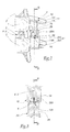
- les figures 3 et 4 sont respectivement des sections prises suivant les lignes III-III de la figure 2 et IV-IV de la figure 3 ; et
- la figure 5 est une section analogue à la figure 4, d'une variante du dispositif selon l'invention.
- FIG. 1 is a perspective view of two adjacent vertebrae equipped with a lateral stabilization device according to the invention, these vertebrae and this device being observed from behind and offset from the sagittal plane of the spine, being represented with an intervertebral spacing greater than normal for reasons of visibility;
- Figure 2 is an elevational view taken along the arrow II of Figure 1, the lateral halves of the vertebrae and the device, Figure 2 corresponding to a view from the front of the spine;
- Figures 3 and 4 are respectively sections taken along the lines III-III of Figure 2 and IV-IV of Figure 3; and
- Figure 5 is a section similar to Figure 4, a variant of the device according to the invention.
Sur les figures 1 et 2 sont représentées deux vertèbres adjacentes 1 et 2 d'un rachis lombaire d'un être humain. La direction longitudinale de ce rachis est référencée 3, les vertèbres 1 et 2 étant séparées l'une de l'autre, suivant cette direction, par un disque intervertébral non représenté sur les figures pour des raisons de visibilité. Par commodité, la suite de la description est orientée par rapport à ces vertèbres dans leur position anatomique, c'est-à-dire que les termes « postérieur » ou « arrière », « antérieur » ou « avant », « droit », « gauche », « supérieur », « inférieur », etc. s'entendent par rapport au rachis du patient se tenant debout. De même, le terme « sagittal » correspond à une direction dans le sens antéro-postérieur, verticalement sur la ligne médiane du rachis, tandis que le terme « médial » correspond à une direction sensiblement perpendiculaire au plan sagittal du rachis, dirigée vers ce rachis, le terme « latéral » correspondant à une direction de sens opposé.Figures 1 and 2 show two
Sur les figures 1 à 4 est représenté un dispositif 4 de stabilisation dynamique des vertèbres 1 et 2, implanté sur le côté gauche des vertèbres, en vue de reproduire la liaison articulaire entre ces vertèbres, notamment lorsque ces dernières sont sollicitées en flexion/extension, tout en assurant un espacement intervertébral satisfaisant. Ce dispositif comporte un élément vertébral supérieur 10 implanté au niveau de la vertèbre 1 et un ensemble vertébral inférieur 20 implanté au niveau de la vertèbre 2.FIGS. 1 to 4 show a device 4 for dynamic stabilization of the
Chaque élément vertébral 10, 20 comporte un corps rigide 11, 21 d'une seule pièce, par exemple métallique, adapté pour être fixé au côté gauche de la vertèbre 1, 2. A cet effet, la partie supérieure 12 du corps 11 et la partie inférieure 22 du corps 21 sont traversées de part en part, suivant une direction médio-latérale, par des orifices 13, 23 destinés à recevoir des vis, non représentées, d'ancrage osseux dans le corps vertébral des vertèbres 1 et 2 pour immobiliser fermement les éléments vertébraux 10 et 20 par rapport aux vertèbres.Each
La partie inférieure 14 de l'élément 10 et la partie supérieure 24 de l'élément 20 sont adaptées pour coopérer l'une avec l'autre lorsque le dispositif 4 est implanté, comme représenté sur la figure 2. En coupe frontale, comme à la figure 4, c'est-à-dire dans un plan de coupe sensiblement vertical et parallèle à une direction médio-latérale, le corps 11, constitué des parties supérieure 12 et inférieure 14 venues de manière l'une avec l'autre, présente une section en forme de L retourné tandis que la partie supérieure 24 présente une section globalement en forme de U. Cette partie supérieure 24 définit ainsi un logement 25 débouchant librement vers le haut et destiné à recevoir la partie inférieure 14. Ce logement 25 est délimité inférieurement par une paroi de fond 26 et, sur ses côtés, par une paroi médiale 27 et une paroi latérale 28 parallèles l'une à l'autre, ces parois 26, 27 et 28 étant venues de matière avec le reste du corps 21.The
L'écartement médio-latéral entre les parois 27 et 28 est sensiblement égal à la dimension médio-latérale de la partie inférieure 14 de l'élément 10 de sorte que, lorsque cette partie est reçue dans le logement 25 comme indiqué par la flèche 5 à la figure 1, elle est retenue suivant une direction médio-latérale, sans possibilité de débattement, à des jeux fonctionnels près, comme représenté sur les figures 2 et 4.The medio-lateral spacing between the
A la différence des surfaces en regard des parois médiale 27 et latérale 28, la surface supérieure 26A de la paroi de fond 26 n'est pas plane mais est bombée avec sa concavité tournée vers le haut. Plus précisément, cette surface 26A correspond à une portion de cylindre d'axe X-X s'étendant au-dessus de la paroi de fond 26 et suivant une direction sensiblement médio-latérale, comme représenté aux figures 2 à 4. Cette surface 26A est adaptée pour guider les mouvements relatifs entre les éléments supérieur 10 et inférieur 20 du dispositif 4, en coopérant par complémentarité de formes avec la surface d'extrémité inférieure 14A de la partie 14 de l'élément 10, cette surface 14A correspondant, elle aussi, à une portion de cylindre d'axe sensiblement confondu avec l'X-X lorsque les éléments sont implantés. Autrement dit, lorsque les éléments 10 et 20 sont fixés aux vertèbres 1 et 2, les surfaces 14A et 26A sont appuyées l'une contre l'autre, de manière basculante autour de l'axe X-X, comme indiqué par la flèche 6 à la figure 3.Unlike the facing surfaces of the medial and
Pour ne pas gêner les mouvements relatifs de basculement entre les éléments 10 et 20, les côtés antérieur et postérieur du logement 25 débouchent librement sur l'extérieur.In order not to hinder the relative tilting movements between the
En service, lorsque le dispositif 4 est implanté sur les vertèbres 1 et 2, les surfaces 14A et 26A coopèrent de manière à guider le basculement entre les vertèbres autour de l'axe X-X. Comme cet axe s'étend avantageusement dans l'espace intervertébral 7 séparant les vertèbres 1 et 2 suivant la direction longitudinale 3 du rachis, en particulier dans la région médiane de cet espace, les mouvements de basculement imposés par la coopération de ces surfaces sont identiques aux ou, tout au moins, très proches des mouvements articulaires intervertébraux anatomiques générés lors d'une flexion ou d'une extension du rachis.In use, when the device 4 is implanted on the
L'implantation latérale du dispositif 4 est particulièrement aisée et rapide puisque seuls les éléments 10 et 20 sont à rapportés fermement aux vertèbres 1 et 2, au moyen des vis d'ancrage osseux précitées. En pratique, les éléments 10 et 20 sont mis en place simultanément, avec la partie inférieure 14 de l'élément 10 reçue dans le logement supérieur 25 de l'élément 20, comme indiqué par la flèche 5 à la figure 1. De la sorte, le chirurgien peut implanter le dispositif 4 avec les surfaces 14A et 26A au contact l'une de l'autre et pour une configuration d'extension prédéterminée des vertèbres. Le dispositif 4 maintient ainsi l'écartement longitudinal des vertèbres 1 et 2, suivant la direction 3, sous une contrainte prédéterminée par le chirurgien. On comprend que, à cet effet, les surfaces 14A et 26A doivent globalement s'étendre selon une direction antéro-postérieure et coopérer ainsi de manière pressante dans la direction longitudinale 3 du rachis. Autrement dit, les surfaces 14A et 26A coopèrent l'une avec l'autre en formant une résultante de contact R s'étendant sensiblement parallèlement à cette direction 3.The lateral implantation of the device 4 is particularly easy and fast since only the
Sur la figure 5 est représentée une variante du dispositif 4, destinée à permettre au dispositif de présenter une légère liberté de débattements internes suivant des directions transversales à une stricte direction médio-latérale, assurant un plus grand confort au patient lors de mouvements de torsion de son rachis, c'est-à-dire de rotation autour de la direction longitudinale du rachis, et/ou d'inclinaison latérale de son rachis. A cet effet, cette variante se distingue du dispositif des figures 1 à 4 par la géométrie des surfaces de guidage coopérantes 14A et 26A : dans cette variante, ces surfaces correspondent sensiblement à une même portion de sphère centrée en un point C situé sur un axe médio-latéral X-X. En principe, les éléments 10 et 20 sont ainsi articulés l'un par rapport à l'autre à la façon d'une rotule de centre C. En pratique, seul le mouvement de basculement autour de l'axe X-X est librement possible, les autres mouvements admissibles étant limités par une tige 8 d'axe longitudinal correspondant à l'axe X-X, qui traverse librement et de part en part la partie inférieure 14 de l'élément 10. Les deux extrémités longitudinales de cette tige 8 sont reçues, avec un jeu de débattement j, dans respectivement des orifices 27A et 28A cylindriques à base circulaire, ménagées à travers les parois médiane 27 et latérale 28 de l'élément 20. Le diamètre des extrémités de la tige 8 est inférieur au diamètre de ces orifices 27A et 28A de manière à définir le jeu de débattement j. De la sorte, les mouvements rotatifs autour du point C entre les éléments 10 et 20, autre que le mouvement de basculement autour de l'axe X-X, ne sont autorisés que jusqu'à ce que les extrémités de la tige 8 butent dans l'une des parois définissant les orifices 27A et 28A.FIG. 5 shows a variant of the device 4, intended to allow the device to present a slight freedom of internal deflections in transverse directions to a strict mediolateral direction, ensuring greater comfort for the patient during torsion movements of his spine, that is to say, rotation around the longitudinal direction of the spine, and / or lateral inclination of his spine. For this purpose, this variant is distinguished from the FIGS. 1 to 4 by the geometry of the cooperating guiding
Pour des raisons de maintien mécanique, des rondelles 30 sont respectivement rapportées autour de chaque extrémité de la tige 8, respectivement en appui contre le côté médial de la paroi 27 et contre le côté latéral de la paroi 28. Chaque rondelle est associée à un écrou de blocage 32, par exemple vissé autour de l'extrémité libre filetée de l'extrémité correspondante de la tige 8.For reasons of mechanical retention, washers 30 are respectively attached around each end of the
Pour éviter que les parois médiale 27 et latérale 28 ne constituent une gêne à ces mouvements de débattement rotatifs entre les éléments 10 et 20, un écartement médio-latéral e non nul est prévu entre, d'une part, la paroi 27 et la face médiale de la partie 14 et, d'autre part, entre la paroi 28 et la face latérale de la partie 14. En outre, les rondelles de retenue 29 montées sur la tige 8 sont disposées à distance des parois 27 et 28.In order to prevent the medial and
En variante, au lieu d'être disposées à distance des parois 27 et 28, les rondelles 29 pourraient être en portion de sphère centrée sur le centre C, les faces externes des parois 27 et 28 ayant la même géométrie.Alternatively, instead of being spaced apart from the
On remarquera que, contrairement au dispositif des figures 1 à 4, dans lesquelles l'axe de basculement médio-latéral X-X est exclusivement défini par la coopération des surfaces 14A et 26A, l'axe de basculement X-X entre les éléments 10 et 20 de la variante du dispositif de la figure 5 est défini, à la fois, par la coopération des surfaces sphériques 14A et 26A et par la présence de la tige 8 matérialisant cet axe. En pratique, la direction de l'axe de basculement X-X pour le dispositif des figures 1 à 4 est imposé de manière sensiblement confondue avec une direction médio-latérale vis-à-vis du rachis tandis que, avec le dispositif de la figure 5, cet axe de basculement X-X peut, au cours de la sollicitation du rachis, être incliné par rapport à la direction médio-latérale au rachis, l'angle maximal α de cette inclinaison étant toutefois limité à quelques degrés seulement, notamment à une dizaine de degrés.It will be noted that, unlike the device of FIGS. 1 to 4, in which the mid-lateral tilting axis XX is exclusively defined by the cooperation of the
Divers aménagements et variantes au dispositif 4 évoqué ci-dessus sont en outre envisageables :
- dans l'exemple de réalisation détaillé ci-dessus, l'axe X-X de basculement entre les éléments 10 et 20 est un axe géométrique ; en variante, on peut prévoir qu'un axe physique s'étend à travers le logement 25 et relie les parois médiale 27
et latérale 28, en étant reçu dans un orifice complémentaire traversant de part en part la partie inférieure 14 de l'élément 10, suivant une direction médio-latérale ; - les courbures des surfaces de guidage 14A et 26A peuvent être inversées ;
- la structure mâle/femelle du dispositif 4 peut être inversée de sorte que, en variante, l'élément vertébral supérieur définit un logement inférieur,
analogue au logement 25, à l'intérieur duquel est reçue la partie supérieure complémentaire de l'élément vertébral inférieur ; - plutôt que de prévoir les surfaces
14A et 26A rigoureusement cylindriques, de sorte qu'elles basculent en glissant l'une contre l'autre autour de l'unique axe X-X, ces surfaces peuvent présenter des profils bombés définissant, lors du basculement relatif entre les éléments 10 et 20, une pluralité d'axes instantanés de rotation, parallèles les uns aux autres et s'étendant suivant des directions médio-latérales ; et/ou - dans l'exemple de réalisation représenté aux figures, le dispositif 4 n'est implanté qu'au niveau du côté gauche des vertèbres 1
et 2 ; en variante, le dispositif comprend, en remplacement des éléments 10 et 20, deux éléments vertébraux analogues aux éléments 10 et 20 et adaptés pour être implantés sur le côté droit des vertèbres ; de même, le dispositif selon l'invention peut comprendre quatre élément vertébraux associés par paires, respectivement prévues sur les côtés gauche et droit des vertèbres ; dans ce cas, pour homogénéiser les comportements cinématiques de ces deux dispositifs, on peut prévoir qu'un axe physique relie les deux paires d'éléments, cet axe s'étendant suivant la direction X-X et constituant un axe de basculement commun pour les deux paires d'éléments, en traversant le disque intervertébral suivant une direction médio-latérale.
- in the embodiment detailed above, the axis XX of tilting between the
elements housing 25 and connects the medial and lateral 27 and 28 walls, being received in a complementary through orifice through and through thelower part 14 of theelement 10, in a mediolateral direction; - the curvatures of the guide surfaces 14A and 26A can be reversed;
- the male / female structure of the device 4 can be reversed so that, alternatively, the upper vertebral element defines a lower housing, similar to the
housing 25, inside which is received the upper complementary part of the lower vertebral element ; - rather than providing
surfaces elements - in the embodiment shown in the figures, the device 4 is implanted only at the left side of the
vertebrae elements elements
Claims (11)
Applications Claiming Priority (1)
| Application Number | Priority Date | Filing Date | Title |
|---|---|---|---|
| FR0512426A FR2894127B1 (en) | 2005-12-07 | 2005-12-07 | DEVICE FOR LATERAL STABILIZATION OF THE RACHIS |
Publications (2)
| Publication Number | Publication Date |
|---|---|
| EP1795137A1 true EP1795137A1 (en) | 2007-06-13 |
| EP1795137B1 EP1795137B1 (en) | 2009-03-04 |
Family
ID=36678394
Family Applications (1)
| Application Number | Title | Priority Date | Filing Date |
|---|---|---|---|
| EP06356139A Active EP1795137B1 (en) | 2005-12-07 | 2006-12-06 | Apparatus for lateral stabilisation of the spine |
Country Status (6)
| Country | Link |
|---|---|
| US (1) | US20070162004A1 (en) |
| EP (1) | EP1795137B1 (en) |
| AT (1) | ATE424152T1 (en) |
| DE (1) | DE602006005447D1 (en) |
| ES (1) | ES2321870T3 (en) |
| FR (1) | FR2894127B1 (en) |
Cited By (1)
| Publication number | Priority date | Publication date | Assignee | Title |
|---|---|---|---|---|
| WO2011012705A1 (en) * | 2009-07-30 | 2011-02-03 | Universite Libre De Bruxelles | Implantable vertebral prosthesis |
Families Citing this family (6)
| Publication number | Priority date | Publication date | Assignee | Title |
|---|---|---|---|---|
| US9381047B2 (en) | 2007-05-09 | 2016-07-05 | Ebi, Llc | Interspinous implant |
| US9173686B2 (en) * | 2007-05-09 | 2015-11-03 | Ebi, Llc | Interspinous implant |
| US8388656B2 (en) * | 2010-02-04 | 2013-03-05 | Ebi, Llc | Interspinous spacer with deployable members and related method |
| US20120323276A1 (en) | 2011-06-17 | 2012-12-20 | Bryan Okamoto | Expandable interspinous device |
| US10603091B2 (en) | 2014-02-24 | 2020-03-31 | Curtin University Of Technology | Fastener |
| CN108778152B (en) | 2016-03-18 | 2022-05-10 | 科廷大学 | Expandable fasteners for orthopedic applications |
Citations (5)
| Publication number | Priority date | Publication date | Assignee | Title |
|---|---|---|---|---|
| US5423816A (en) * | 1993-07-29 | 1995-06-13 | Lin; Chih I. | Intervertebral locking device |
| JPH10277070A (en) | 1997-04-09 | 1998-10-20 | Shigeo Sano | Artificial intervertebral joint |
| DE29814320U1 (en) | 1998-08-10 | 1998-11-26 | Schwenk Bruno | Spinal stiffening implant |
| US6296644B1 (en) | 1998-08-26 | 2001-10-02 | Jean Saurat | Spinal instrumentation system with articulated modules |
| US20050113927A1 (en) * | 2003-11-25 | 2005-05-26 | Malek Michel H. | Spinal stabilization systems |
Family Cites Families (4)
| Publication number | Priority date | Publication date | Assignee | Title |
|---|---|---|---|---|
| SE8901315L (en) * | 1989-04-11 | 1990-10-12 | Bjoern Albrektsson | Joint prosthesis |
| US6974478B2 (en) * | 1999-10-22 | 2005-12-13 | Archus Orthopedics, Inc. | Prostheses, systems and methods for replacement of natural facet joints with artificial facet joint surfaces |
| US7316822B2 (en) * | 2003-11-26 | 2008-01-08 | Ethicon, Inc. | Conformable tissue repair implant capable of injection delivery |
| US7909852B2 (en) * | 2004-03-31 | 2011-03-22 | Depuy Spine Sarl | Adjustable-angle spinal fixation element |
-
2005
- 2005-12-07 FR FR0512426A patent/FR2894127B1/en not_active Expired - Fee Related
-
2006
- 2006-12-06 EP EP06356139A patent/EP1795137B1/en active Active
- 2006-12-06 DE DE602006005447T patent/DE602006005447D1/en active Active
- 2006-12-06 AT AT06356139T patent/ATE424152T1/en not_active IP Right Cessation
- 2006-12-06 US US11/634,378 patent/US20070162004A1/en not_active Abandoned
- 2006-12-06 ES ES06356139T patent/ES2321870T3/en active Active
Patent Citations (5)
| Publication number | Priority date | Publication date | Assignee | Title |
|---|---|---|---|---|
| US5423816A (en) * | 1993-07-29 | 1995-06-13 | Lin; Chih I. | Intervertebral locking device |
| JPH10277070A (en) | 1997-04-09 | 1998-10-20 | Shigeo Sano | Artificial intervertebral joint |
| DE29814320U1 (en) | 1998-08-10 | 1998-11-26 | Schwenk Bruno | Spinal stiffening implant |
| US6296644B1 (en) | 1998-08-26 | 2001-10-02 | Jean Saurat | Spinal instrumentation system with articulated modules |
| US20050113927A1 (en) * | 2003-11-25 | 2005-05-26 | Malek Michel H. | Spinal stabilization systems |
Non-Patent Citations (1)
| Title |
|---|
| PATENT ABSTRACTS OF JAPAN vol. 1999, no. 01 29 January 1999 (1999-01-29) * |
Cited By (1)
| Publication number | Priority date | Publication date | Assignee | Title |
|---|---|---|---|---|
| WO2011012705A1 (en) * | 2009-07-30 | 2011-02-03 | Universite Libre De Bruxelles | Implantable vertebral prosthesis |
Also Published As
| Publication number | Publication date |
|---|---|
| ATE424152T1 (en) | 2009-03-15 |
| FR2894127B1 (en) | 2008-08-22 |
| ES2321870T3 (en) | 2009-06-12 |
| DE602006005447D1 (en) | 2009-04-16 |
| US20070162004A1 (en) | 2007-07-12 |
| FR2894127A1 (en) | 2007-06-08 |
| EP1795137B1 (en) | 2009-03-04 |
Similar Documents
| Publication | Publication Date | Title |
|---|---|---|
| EP1795136B1 (en) | Apparatus for dynamic stabilisation of the spine | |
| EP1997449A2 (en) | Device and assembly for rear dynamic guidance of the spine and spine treatment system comprising such a device | |
| EP1795137B1 (en) | Apparatus for lateral stabilisation of the spine | |
| EP1443879B1 (en) | Posterior vertebral joint prosthesis | |
| EP1337193B1 (en) | Intervertebral stabilising device | |
| EP1414358B1 (en) | Vertebra stabilizing assembly | |
| EP1233711B1 (en) | Intervertebral stabilising device | |
| EP1054638B1 (en) | Interspinous stabiliser to be fixed to spinous processes of two vertebrae | |
| EP0986339B1 (en) | Multidirectional adaptable vertebral osteosynthesis device with reduced space requirement | |
| FR2833151A1 (en) | BONE ANCHORING IMPLANT WITH POLYAXIAL HEAD | |
| EP1795135B1 (en) | Apparatus for lateral dynamic lateral stabilisation of the spine | |
| WO1995005785A1 (en) | Device for anchoring rachidian instrumentation on a vertebra | |
| FR2884136A1 (en) | INTERVERTEBRAL SURGICAL IMPLANT FORMING BALL | |
| FR2801782A1 (en) | Intervertebral stabiliser comprises implant between adjacent vertebrae and movement damper to rear of spine | |
| FR2929105A1 (en) | PROSTHESIS OF VERTEBRAL DISC, IN PARTICULAR FOR CERVICAL VERTEBRATES | |
| WO2009092907A2 (en) | Intervertebral disc prosthesis | |
| EP2398423B1 (en) | Intervertebral disc prosthesis | |
| WO2000076412A1 (en) | Backbone implant with lateral linkage by anterior path | |
| EP2378991B1 (en) | "rod screw" dynamic implant for stabilizing a vertebral column | |
| EP1706076A1 (en) | Intervertebral discal prosthesis | |
| FR2918261A1 (en) | DEVICE FOR CONNECTING AT LEAST THREE VERTEBRATES BETWEEN THEM |
Legal Events
| Date | Code | Title | Description |
|---|---|---|---|
| PUAI | Public reference made under article 153(3) epc to a published international application that has entered the european phase |
Free format text: ORIGINAL CODE: 0009012 |
|
| AK | Designated contracting states |
Kind code of ref document: A1 Designated state(s): AT BE BG CH CY CZ DE DK EE ES FI FR GB GR HU IE IS IT LI LT LU LV MC NL PL PT RO SE SI SK TR |
|
| AX | Request for extension of the european patent |
Extension state: AL BA HR MK YU |
|
| 17P | Request for examination filed |
Effective date: 20071205 |
|
| AKX | Designation fees paid |
Designated state(s): AT BE BG CH CY CZ DE DK EE ES FI FR GB GR HU IE IS IT LI LT LU LV MC NL PL PT RO SE SI SK TR |
|
| GRAP | Despatch of communication of intention to grant a patent |
Free format text: ORIGINAL CODE: EPIDOSNIGR1 |
|
| GRAS | Grant fee paid |
Free format text: ORIGINAL CODE: EPIDOSNIGR3 |
|
| GRAA | (expected) grant |
Free format text: ORIGINAL CODE: 0009210 |
|
| RAP1 | Party data changed (applicant data changed or rights of an application transferred) |
Owner name: PHUSIS |
|
| AK | Designated contracting states |
Kind code of ref document: B1 Designated state(s): AT BE BG CH CY CZ DE DK EE ES FI FR GB GR HU IE IS IT LI LT LU LV MC NL PL PT RO SE SI SK TR |
|
| REG | Reference to a national code |
Ref country code: GB Ref legal event code: FG4D Free format text: NOT ENGLISH |
|
| REG | Reference to a national code |
Ref country code: CH Ref legal event code: EP |
|
| REG | Reference to a national code |
Ref country code: IE Ref legal event code: FG4D Free format text: LANGUAGE OF EP DOCUMENT: FRENCH |
|
| REF | Corresponds to: |
Ref document number: 602006005447 Country of ref document: DE Date of ref document: 20090416 Kind code of ref document: P |
|
| REG | Reference to a national code |
Ref country code: ES Ref legal event code: FG2A Ref document number: 2321870 Country of ref document: ES Kind code of ref document: T3 |
|
| PG25 | Lapsed in a contracting state [announced via postgrant information from national office to epo] |
Ref country code: SI Free format text: LAPSE BECAUSE OF FAILURE TO SUBMIT A TRANSLATION OF THE DESCRIPTION OR TO PAY THE FEE WITHIN THE PRESCRIBED TIME-LIMIT Effective date: 20090304 Ref country code: FI Free format text: LAPSE BECAUSE OF FAILURE TO SUBMIT A TRANSLATION OF THE DESCRIPTION OR TO PAY THE FEE WITHIN THE PRESCRIBED TIME-LIMIT Effective date: 20090304 Ref country code: LT Free format text: LAPSE BECAUSE OF FAILURE TO SUBMIT A TRANSLATION OF THE DESCRIPTION OR TO PAY THE FEE WITHIN THE PRESCRIBED TIME-LIMIT Effective date: 20090304 |
|
| PG25 | Lapsed in a contracting state [announced via postgrant information from national office to epo] |
Ref country code: SE Free format text: LAPSE BECAUSE OF FAILURE TO SUBMIT A TRANSLATION OF THE DESCRIPTION OR TO PAY THE FEE WITHIN THE PRESCRIBED TIME-LIMIT Effective date: 20090604 Ref country code: LV Free format text: LAPSE BECAUSE OF FAILURE TO SUBMIT A TRANSLATION OF THE DESCRIPTION OR TO PAY THE FEE WITHIN THE PRESCRIBED TIME-LIMIT Effective date: 20090304 Ref country code: AT Free format text: LAPSE BECAUSE OF FAILURE TO SUBMIT A TRANSLATION OF THE DESCRIPTION OR TO PAY THE FEE WITHIN THE PRESCRIBED TIME-LIMIT Effective date: 20090304 Ref country code: PL Free format text: LAPSE BECAUSE OF FAILURE TO SUBMIT A TRANSLATION OF THE DESCRIPTION OR TO PAY THE FEE WITHIN THE PRESCRIBED TIME-LIMIT Effective date: 20090304 |
|
| PG25 | Lapsed in a contracting state [announced via postgrant information from national office to epo] |
Ref country code: CZ Free format text: LAPSE BECAUSE OF FAILURE TO SUBMIT A TRANSLATION OF THE DESCRIPTION OR TO PAY THE FEE WITHIN THE PRESCRIBED TIME-LIMIT Effective date: 20090304 Ref country code: EE Free format text: LAPSE BECAUSE OF FAILURE TO SUBMIT A TRANSLATION OF THE DESCRIPTION OR TO PAY THE FEE WITHIN THE PRESCRIBED TIME-LIMIT Effective date: 20090304 Ref country code: PT Free format text: LAPSE BECAUSE OF FAILURE TO SUBMIT A TRANSLATION OF THE DESCRIPTION OR TO PAY THE FEE WITHIN THE PRESCRIBED TIME-LIMIT Effective date: 20090818 |
|
| PG25 | Lapsed in a contracting state [announced via postgrant information from national office to epo] |
Ref country code: IS Free format text: LAPSE BECAUSE OF FAILURE TO SUBMIT A TRANSLATION OF THE DESCRIPTION OR TO PAY THE FEE WITHIN THE PRESCRIBED TIME-LIMIT Effective date: 20090704 Ref country code: RO Free format text: LAPSE BECAUSE OF FAILURE TO SUBMIT A TRANSLATION OF THE DESCRIPTION OR TO PAY THE FEE WITHIN THE PRESCRIBED TIME-LIMIT Effective date: 20090304 Ref country code: SK Free format text: LAPSE BECAUSE OF FAILURE TO SUBMIT A TRANSLATION OF THE DESCRIPTION OR TO PAY THE FEE WITHIN THE PRESCRIBED TIME-LIMIT Effective date: 20090304 |
|
| PLBE | No opposition filed within time limit |
Free format text: ORIGINAL CODE: 0009261 |
|
| STAA | Information on the status of an ep patent application or granted ep patent |
Free format text: STATUS: NO OPPOSITION FILED WITHIN TIME LIMIT |
|
| PG25 | Lapsed in a contracting state [announced via postgrant information from national office to epo] |
Ref country code: BG Free format text: LAPSE BECAUSE OF FAILURE TO SUBMIT A TRANSLATION OF THE DESCRIPTION OR TO PAY THE FEE WITHIN THE PRESCRIBED TIME-LIMIT Effective date: 20090604 Ref country code: DK Free format text: LAPSE BECAUSE OF FAILURE TO SUBMIT A TRANSLATION OF THE DESCRIPTION OR TO PAY THE FEE WITHIN THE PRESCRIBED TIME-LIMIT Effective date: 20090304 |
|
| PGFP | Annual fee paid to national office [announced via postgrant information from national office to epo] |
Ref country code: ES Payment date: 20091223 Year of fee payment: 4 Ref country code: IE Payment date: 20091231 Year of fee payment: 4 |
|
| 26N | No opposition filed |
Effective date: 20091207 |
|
| PGFP | Annual fee paid to national office [announced via postgrant information from national office to epo] |
Ref country code: NL Payment date: 20091222 Year of fee payment: 4 |
|
| PGFP | Annual fee paid to national office [announced via postgrant information from national office to epo] |
Ref country code: FR Payment date: 20091229 Year of fee payment: 4 Ref country code: LU Payment date: 20100212 Year of fee payment: 4 |
|
| PGFP | Annual fee paid to national office [announced via postgrant information from national office to epo] |
Ref country code: BE Payment date: 20100212 Year of fee payment: 4 Ref country code: DE Payment date: 20091214 Year of fee payment: 4 |
|
| PG25 | Lapsed in a contracting state [announced via postgrant information from national office to epo] |
Ref country code: MC Free format text: LAPSE BECAUSE OF NON-PAYMENT OF DUE FEES Effective date: 20100701 |
|
| PG25 | Lapsed in a contracting state [announced via postgrant information from national office to epo] |
Ref country code: GR Free format text: LAPSE BECAUSE OF FAILURE TO SUBMIT A TRANSLATION OF THE DESCRIPTION OR TO PAY THE FEE WITHIN THE PRESCRIBED TIME-LIMIT Effective date: 20090605 |
|
| BERE | Be: lapsed |
Owner name: PHUSIS Effective date: 20101231 |
|
| PG25 | Lapsed in a contracting state [announced via postgrant information from national office to epo] |
Ref country code: HU Free format text: LAPSE BECAUSE OF FAILURE TO SUBMIT A TRANSLATION OF THE DESCRIPTION OR TO PAY THE FEE WITHIN THE PRESCRIBED TIME-LIMIT Effective date: 20090905 |
|
| REG | Reference to a national code |
Ref country code: NL Ref legal event code: V1 Effective date: 20110701 |
|
| REG | Reference to a national code |
Ref country code: CH Ref legal event code: PL |
|
| GBPC | Gb: european patent ceased through non-payment of renewal fee |
Effective date: 20101206 |
|
| PG25 | Lapsed in a contracting state [announced via postgrant information from national office to epo] |
Ref country code: TR Free format text: LAPSE BECAUSE OF FAILURE TO SUBMIT A TRANSLATION OF THE DESCRIPTION OR TO PAY THE FEE WITHIN THE PRESCRIBED TIME-LIMIT Effective date: 20090304 |
|
| REG | Reference to a national code |
Ref country code: FR Ref legal event code: ST Effective date: 20110831 |
|
| PG25 | Lapsed in a contracting state [announced via postgrant information from national office to epo] |
Ref country code: CY Free format text: LAPSE BECAUSE OF FAILURE TO SUBMIT A TRANSLATION OF THE DESCRIPTION OR TO PAY THE FEE WITHIN THE PRESCRIBED TIME-LIMIT Effective date: 20090304 Ref country code: BE Free format text: LAPSE BECAUSE OF NON-PAYMENT OF DUE FEES Effective date: 20101231 |
|
| PG25 | Lapsed in a contracting state [announced via postgrant information from national office to epo] |
Ref country code: IE Free format text: LAPSE BECAUSE OF NON-PAYMENT OF DUE FEES Effective date: 20101206 Ref country code: CH Free format text: LAPSE BECAUSE OF NON-PAYMENT OF DUE FEES Effective date: 20101231 Ref country code: LI Free format text: LAPSE BECAUSE OF NON-PAYMENT OF DUE FEES Effective date: 20101231 Ref country code: FR Free format text: LAPSE BECAUSE OF NON-PAYMENT OF DUE FEES Effective date: 20110103 |
|
| PG25 | Lapsed in a contracting state [announced via postgrant information from national office to epo] |
Ref country code: GB Free format text: LAPSE BECAUSE OF NON-PAYMENT OF DUE FEES Effective date: 20101206 Ref country code: DE Free format text: LAPSE BECAUSE OF NON-PAYMENT OF DUE FEES Effective date: 20110701 |
|
| REG | Reference to a national code |
Ref country code: DE Ref legal event code: R119 Ref document number: 602006005447 Country of ref document: DE Effective date: 20110701 |
|
| PG25 | Lapsed in a contracting state [announced via postgrant information from national office to epo] |
Ref country code: NL Free format text: LAPSE BECAUSE OF NON-PAYMENT OF DUE FEES Effective date: 20110701 |
|
| PGFP | Annual fee paid to national office [announced via postgrant information from national office to epo] |
Ref country code: IT Payment date: 20091231 Year of fee payment: 4 |
|
| REG | Reference to a national code |
Ref country code: ES Ref legal event code: FD2A Effective date: 20120220 |
|
| PG25 | Lapsed in a contracting state [announced via postgrant information from national office to epo] |
Ref country code: ES Free format text: LAPSE BECAUSE OF NON-PAYMENT OF DUE FEES Effective date: 20101207 |
|
| PG25 | Lapsed in a contracting state [announced via postgrant information from national office to epo] |
Ref country code: LU Free format text: LAPSE BECAUSE OF NON-PAYMENT OF DUE FEES Effective date: 20101206 |