EP1794518B1 - A fresh keeper - Google Patents
A fresh keeper Download PDFInfo
- Publication number
- EP1794518B1 EP1794518B1 EP05700418A EP05700418A EP1794518B1 EP 1794518 B1 EP1794518 B1 EP 1794518B1 EP 05700418 A EP05700418 A EP 05700418A EP 05700418 A EP05700418 A EP 05700418A EP 1794518 B1 EP1794518 B1 EP 1794518B1
- Authority
- EP
- European Patent Office
- Prior art keywords
- drawer
- fresh keeper
- fresh
- inner drawer
- keeper according
- Prior art date
- Legal status (The legal status is an assumption and is not a legal conclusion. Google has not performed a legal analysis and makes no representation as to the accuracy of the status listed.)
- Expired - Lifetime
Links
Images


Classifications
-
- F—MECHANICAL ENGINEERING; LIGHTING; HEATING; WEAPONS; BLASTING
- F25—REFRIGERATION OR COOLING; COMBINED HEATING AND REFRIGERATION SYSTEMS; HEAT PUMP SYSTEMS; MANUFACTURE OR STORAGE OF ICE; LIQUEFACTION SOLIDIFICATION OF GASES
- F25D—REFRIGERATORS; COLD ROOMS; ICE-BOXES; COOLING OR FREEZING APPARATUS NOT OTHERWISE PROVIDED FOR
- F25D25/00—Charging, supporting, and discharging the articles to be cooled
- F25D25/02—Charging, supporting, and discharging the articles to be cooled by shelves
- F25D25/024—Slidable shelves
- F25D25/025—Drawers
-
- F—MECHANICAL ENGINEERING; LIGHTING; HEATING; WEAPONS; BLASTING
- F25—REFRIGERATION OR COOLING; COMBINED HEATING AND REFRIGERATION SYSTEMS; HEAT PUMP SYSTEMS; MANUFACTURE OR STORAGE OF ICE; LIQUEFACTION SOLIDIFICATION OF GASES
- F25D—REFRIGERATORS; COLD ROOMS; ICE-BOXES; COOLING OR FREEZING APPARATUS NOT OTHERWISE PROVIDED FOR
- F25D17/00—Arrangements for circulating cooling fluids; Arrangements for circulating gas, e.g. air, within refrigerated spaces
- F25D17/04—Arrangements for circulating cooling fluids; Arrangements for circulating gas, e.g. air, within refrigerated spaces for circulating air, e.g. by convection
- F25D17/042—Air treating means within refrigerated spaces
-
- F—MECHANICAL ENGINEERING; LIGHTING; HEATING; WEAPONS; BLASTING
- F25—REFRIGERATION OR COOLING; COMBINED HEATING AND REFRIGERATION SYSTEMS; HEAT PUMP SYSTEMS; MANUFACTURE OR STORAGE OF ICE; LIQUEFACTION SOLIDIFICATION OF GASES
- F25D—REFRIGERATORS; COLD ROOMS; ICE-BOXES; COOLING OR FREEZING APPARATUS NOT OTHERWISE PROVIDED FOR
- F25D2325/00—Charging, supporting or discharging the articles to be cooled, not provided for in other groups of this subclass
- F25D2325/022—Shelves made of glass or ceramic
Definitions
- the invention relates to a fresh keeper. More particularly, the invention relates to a fresh keeper for a refrigerating apparatus.
- a kind of sealed box is also used to keep fresh. Some sealed material are used in the sealed box while the sealed box could not well prevent water from diffusing, because the vapor pressure of air in the box forces the humidity in the box to balance with that of ambience through a small aperture, therefore water would diffuse quickly and the temperature would not be stable if there is even a small aperture, even if the food is stored in a sealed box.
- US 2003115892 A1 discloses a food storage compartment comprising a lower section, an upper section, a receptacle, a partition plate and an inner housing.
- the food storage compartment according to US 2003115892 further comprises a thermoelectric devise to establish a flow of temperature controlled air.
- the outer housing is integrated with the electric circuitry and the internal air streams of the refrigerator for powering the fan and circulating cold air through the device, and the inner housing is fixedly mounted in the outer housing.
- US 3680941 discloses a housing holding a drawer.
- the housing is fixedly mounted in the refrigerator.
- the prior device keeping fresh above can not provide stable humidity and temperature which is useful to keep vegetable and fruits fresh.
- the object of the invention is to provide a fresh keeper which can ensure stable temperature and higher humidity thereof, therefore the invention could prevent the water contained in the food from diffusing.
- said outer drawer consists of a left sidewall, a right sidewall, a back and a bottom
- said inner drawer consists of a left sidewall, a right sidewall, a back, a bottom and a front
- said front is single-layer or double-layer.
- said outer drawer and inner drawer is opened on top.
- an isolating device is provided between said inner drawer and said outer drawer.
- said isolating device is at least one protrusion provided outside said inner drawer or inside said outer drawer.
- said isolating device is a flange provided on at least one sidewall of said inner drawer.
- two integrated guides are provided on the edge of the bottom of said outer drawer such that said inner drawer could be supported on the integrated guides.
- At least one cylindrical portion is provided on the bottom outside said inner drawer or the top inside said outer drawer.
- said lid is formed with transparent material or translucent material.
- said gap is 10mm.
- one or more movable dividing plates are put in said inner drawer.
- the invention as compared with the prior art has following advantages:
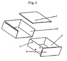
- the fresh keeper shown in figure 1 consists of a lid 1, an outer drawer 2 and an inner drawer 3.
- the inner drawer 3 could be several drawers in which different foods may be put.
- the inner drawer 3 is smaller than the outer drawer by a predetermined size.
- At least one protrusion 5 is provided in the sidewalls and the bottom of the inner drawer 3, when the inner drawer 3 is set in the outer drawer 2, a desired distance is kept between the inner drawer 3 and the outer drawer 2 due to the protrusion 5, thus an air insulation is formed between the inner drawer 3 and the outer drawer 2, as shown in figure 2 , the protrusions 5 could also be provided on the sidewall and the bottom of the outer drawer 2.
- the gap of the air insulation between the inner drawer 3 and the outer drawer 2 is 5mm-30mm because of the difference of their sizes.
- the gap is 10mm.
- the front 4 of the inner drawer is double-layer.
- a flange 6 may be provided in the predetermined position of the two sidewalls and the back of the inner drawer 3, the flange 6 is preferably provided on the top, as shown in figure 3 , thus a desired distance exists between the sidewalls and the back of the outer drawer 2 and those of inner drawer 3; preferably, two integrated guides 8 are provided on the edge of the bottom of the inner drawer 2, as shown in figure 5 , thus the inner drawer 3 is supported on the integrated guides 8 of the outer drawer 2, when the fresh keeper is in close state, a desired distance exists between the bottom of the inner drawer and that of the outer drawer, as shown in figure 4 .
- an outer drawer 2 having four sidewalls and a bottom, and a inner drawer 3 having four sidewalls and a bottom could also be used, the inner drawer 3 could be put into the outer drawer 2 directly, a cylindrical portion 7 is provided on the bottom of said inner drawer 3, the cylindrical portion 7 could also be provided in the corresponding position inside said outer drawer 2, therefore a desired distance exists between the bottom of the inner drawer and that of the outer drawer.
- a flange 6 could be provided at predetermined position in the four sidewalls of the inner drawer 3, the flange is preferably set on the top, as shown in figures 6 and 7 , therefore a desired distance exists between the sidewalls of the inner drawer 3 and those of the outer drawer 2 when the inner drawer 3 is put into the outer drawer 2.
- the distance between the sidewalls and the bottoms of the two drawers forms an air isolating layer.
- a sealed space is formed inside.
- a handle may be provided on the lid 1 to facilitate to open/close the lid 1.
- the outer drawer 2 may also be formed integrally with said lid 1, a flange 5 is provided on the left and right sidewalls of the inner drawer 3 respectively, a flange 10 is also provided on the left and right sidewalls of the outer drawer 2 respectively, as shown in figure 8 , a stiffener 9 extending in the direction parallel to the back is provided on the lid of the outer drawer 2 at the distance from the back of the outer drawer, as shown in figure 9 , when the inner drawer 3 is put into the outer drawer 2, the flanges 5 of the inner drawer 3 could overlap with the flanges 10 of the outer drawer 2, the back of the inner drawer could put against the stiffener 9, therefore a distance could be formed between the left and right sidewalls, the back, the bottom of the inner drawer and those of the outer drawer.
- a removable dividing plate which divides the inner drawer into several areas is provided in the inner drawer 3 to facilitate to store the food.
- Perishable products like vegetables that are not closely packed in moisture proof material stand the risk of dehydration. To avoid this they require an environment with high (>95%) and stable relative humidity and a low (-1-0°C) and stable temperature to keep them fresh.
- the fluctuations of temperature and humidity should lie within ⁇ 0.5°Cand ⁇ 5 % respectively.
- a lettuce head was put in the fresh keeper as shown in figure 6 and one into the vegetable drawer of the prior art. Lettuce was chosen because it is a perishable vegetable with a large surface area. The duration of the test was 18 days without opening the refrigerator. Temperature and relative humidity were measured. -
- the weight reduction of the lettuce in the fresh keeper of the invention is only 7% compared to 18% in the conventional vegetable drawer. It should be noted that, before the test started the lettuce head put into the conventional vegetable drawer was physically larger compared to the one put into the fresh keeper of the invention, and an appreciable difference could be observed when comparing the two lettuce heads after the test.
- FIG. 1 A test was performed on the fresh keeper of the invention as shown in figure 1 .
- the results of the test show that, the relative humidity in the fresh keeper of the invention varies between 87-90%, and a fluctuation of only ⁇ 1.5% relative humidity is achieved much less than the allowable fluctuation of ⁇ 5%, as shown in figure 11.
- Figure 11 is a graph showing the variation of the humidity in the fresh keeper of the invention and that in the vegetable drawer. It could be seen appreciably that the fluctuation of relative humidity in the fresh keeper of the invention is less than that in the vegetable drawer of the prior art.
- the temperature in the fresh keeper of the invention fluctuates between approximately 4.8-5.1 °C, a fluctuation of only ⁇ 0.15°C, far below the desired value of ⁇ 0.5°C, as shown in figure 12.
- Figure 12 is a graph showing the variation of the temperature in the fresh keeper of the invention and that in the vegetable drawer of the prior art. It could be seen appreciably that the fluctuation of relative humidity in the fresh keeper of the invention is far below that in the vegetable drawer of the prior art.
Landscapes
- Engineering & Computer Science (AREA)
- Chemical & Material Sciences (AREA)
- Combustion & Propulsion (AREA)
- Physics & Mathematics (AREA)
- Mechanical Engineering (AREA)
- Thermal Sciences (AREA)
- General Engineering & Computer Science (AREA)
- Cold Air Circulating Systems And Constructional Details In Refrigerators (AREA)
- Packages (AREA)
- Electrical Discharge Machining, Electrochemical Machining, And Combined Machining (AREA)
- Centrifugal Separators (AREA)
Abstract
Description
- The invention relates to a fresh keeper. More particularly, the invention relates to a fresh keeper for a refrigerating apparatus.
- The two most important factors affecting the shelf-life of refrigerated food are temperature and humidity. So far most of the attention has been aimed at controlling just the temperature of the refrigerators; there are not a method and a device keeping fresh by controlling the humidity.
- Several fresh keepers have been used in refrigerating apparatus. A kind of fresh keeper is widely used at present. This fresh keeper consists of a simple single-layer drawer which was not sealed well, thus the temperature in the drawer is not stable and water diffuses quickly while the temperature and the humidity of ambience and their variation have influence on those inside the drawer, thereby the food contained in the drawer is easy to perish or dehydrate.
- A kind of sealed box is also used to keep fresh. Some sealed material are used in the sealed box while the sealed box could not well prevent water from diffusing, because the vapor pressure of air in the box forces the humidity in the box to balance with that of ambience through a small aperture, therefore water would diffuse quickly and the temperature would not be stable if there is even a small aperture, even if the food is stored in a sealed box.
- There is further a fresh keeper to adjust the humidity thereof by means of a mechanical adjusting structure, but the mechanical adjusting structure could not keep the humidity inside the box stable exactly.
-
US 2003115892 A1 discloses a food storage compartment comprising a lower section, an upper section, a receptacle, a partition plate and an inner housing. The food storage compartment according toUS 2003115892 further comprises a thermoelectric devise to establish a flow of temperature controlled air. The outer housing is integrated with the electric circuitry and the internal air streams of the refrigerator for powering the fan and circulating cold air through the device, and the inner housing is fixedly mounted in the outer housing. -
US 3680941 discloses a housing holding a drawer. The housing is fixedly mounted in the refrigerator. -
- The prior device keeping fresh above can not provide stable humidity and temperature which is useful to keep vegetable and fruits fresh.
- The object of the invention is to provide a fresh keeper which can ensure stable temperature and higher humidity thereof, therefore the invention could prevent the water contained in the food from diffusing.
- To achieve the object of the invention a fresh keeper according to
claim 1 is provided. - According to the invention, said outer drawer consists of a left sidewall, a right sidewall, a back and a bottom, said inner drawer consists of a left sidewall, a right sidewall, a back, a bottom and a front, said front is single-layer or double-layer.
- According to the invention, said outer drawer and inner drawer is opened on top.
- According to the invention, an isolating device is provided between said inner drawer and said outer drawer.
- According to the invention, said isolating device is at least one protrusion provided outside said inner drawer or inside said outer drawer.
- According to the invention, said isolating device is a flange provided on at least one sidewall of said inner drawer.
- According to the invention, two integrated guides are provided on the edge of the bottom of said outer drawer such that said inner drawer could be supported on the integrated guides.
- According to the invention, at least one cylindrical portion is provided on the bottom outside said inner drawer or the top inside said outer drawer.
- According to the invention, said lid is formed with transparent material or translucent material.
- According to the invention, said gap is 5mm-30mm.
- According to the invention, said gap is 10mm.
- According to the invention, one or more movable dividing plates are put in said inner drawer.
- The invention, as compared with the prior art has following advantages:
- First, the fresh keeper is equivalent to be thickened due to the air isolating layer in the invention so that the effect of heat preservation is improved, thereby the temperature inside the fresh keeper is not easily influenced by ambience, and the temperature inside the fresh keeper is more stable.
- Second, because of the double-layer structure used in the invention, an air layer is formed. The pressure of the vapor in the air layer is much more than that in the inner drawer, thus it is difficult for the vapor in the inner drawer to diffuse into the air layer, and thereby the moisture in the inner drawer is ensured so that the humidity therein is kept to be a higher value.
- The invention is described in more detail below, with reference to the accompanying drawings, in which:
-
Figure 1 is an exploded view of the fresh keeper according to the first embodiment of the invention; -
Figure 2 is a sectional view of the fresh keeper infigure 1 , in the tightly engaged state; -
Figure 3 is an exploded view of the fresh keeper according to the second embodiment of the invention; -
Figure 4 is a sectional view of the fresh keeper infigure 3 , in the tightly engaged state; -
Figure 5 is a sectional view taken along line A-A infigure 4 ; -
Figure 6 is an exploded view of the fresh keeper according to the third embodiment of the invention; -
Figure 7 is a sectional view of the fresh keeper infigure 6 , in the tightly engaged state; -
Figure 8 is an exploded view of the fresh keeper according to the forth embodiment of the invention; -
Figure 9 is a sectional view of the fresh keeper infigure 8 , in the tightly engaged state; -
Figure 10 is a sectional view taken along line B-B infigure 9 ; -
Figure 11 is a graph showing the comparison between the variation of the relative humidity in the fresh keeper of the invention and that in the vegetable drawer of prior art; -
Figure 12 is a graph showing the comparison between the variation of the temperature in the fresh keeper of the invention and that in the vegetable drawer of prior art. - The fresh keeper shown in
figure 1 consists of alid 1, anouter drawer 2 and aninner drawer 3. Theinner drawer 3 could be several drawers in which different foods may be put. Theinner drawer 3 is smaller than the outer drawer by a predetermined size. When theinner drawer 3 is put into theouter drawer 2, thelid 1 is installed on theouter drawer 2, afront wall 4 of theinner drawer 3 lies against two sidewalls, a bottom and thelid 1 of theouter drawer 2, thereby a sealed space is formed inside theinner drawer 3. At least oneprotrusion 5 is provided in the sidewalls and the bottom of theinner drawer 3, when theinner drawer 3 is set in theouter drawer 2, a desired distance is kept between theinner drawer 3 and theouter drawer 2 due to theprotrusion 5, thus an air insulation is formed between theinner drawer 3 and theouter drawer 2, as shown infigure 2 , theprotrusions 5 could also be provided on the sidewall and the bottom of theouter drawer 2. The gap of the air insulation between theinner drawer 3 and theouter drawer 2 is 5mm-30mm because of the difference of their sizes. Preferably, the gap is 10mm. Preferably, thefront 4 of the inner drawer is double-layer. - A
flange 6 may be provided in the predetermined position of the two sidewalls and the back of theinner drawer 3, theflange 6 is preferably provided on the top, as shown infigure 3 , thus a desired distance exists between the sidewalls and the back of theouter drawer 2 and those ofinner drawer 3; preferably, two integrated guides 8 are provided on the edge of the bottom of theinner drawer 2, as shown infigure 5 , thus theinner drawer 3 is supported on the integrated guides 8 of theouter drawer 2, when the fresh keeper is in close state, a desired distance exists between the bottom of the inner drawer and that of the outer drawer, as shown infigure 4 . - As shown in
figure 6 , anouter drawer 2 having four sidewalls and a bottom, and ainner drawer 3 having four sidewalls and a bottom could also be used, theinner drawer 3 could be put into theouter drawer 2 directly, a cylindrical portion 7 is provided on the bottom of saidinner drawer 3, the cylindrical portion 7 could also be provided in the corresponding position inside saidouter drawer 2, therefore a desired distance exists between the bottom of the inner drawer and that of the outer drawer. Aflange 6 could be provided at predetermined position in the four sidewalls of theinner drawer 3, the flange is preferably set on the top, as shown infigures 6 and 7 , therefore a desired distance exists between the sidewalls of theinner drawer 3 and those of theouter drawer 2 when theinner drawer 3 is put into theouter drawer 2. The distance between the sidewalls and the bottoms of the two drawers forms an air isolating layer. When thelid 1 covers theouter drawer 2, a sealed space is formed inside. Preferably, a handle may be provided on thelid 1 to facilitate to open/close thelid 1. - The
outer drawer 2 may also be formed integrally with saidlid 1, aflange 5 is provided on the left and right sidewalls of theinner drawer 3 respectively, aflange 10 is also provided on the left and right sidewalls of theouter drawer 2 respectively, as shown infigure 8 , a stiffener 9 extending in the direction parallel to the back is provided on the lid of theouter drawer 2 at the distance from the back of the outer drawer, as shown infigure 9 , when theinner drawer 3 is put into theouter drawer 2, theflanges 5 of theinner drawer 3 could overlap with theflanges 10 of theouter drawer 2, the back of the inner drawer could put against the stiffener 9, therefore a distance could be formed between the left and right sidewalls, the back, the bottom of the inner drawer and those of the outer drawer. - A removable dividing plate which divides the inner drawer into several areas is provided in the
inner drawer 3 to facilitate to store the food. - Perishable products like vegetables that are not closely packed in moisture proof material stand the risk of dehydration. To avoid this they require an environment with high (>95%) and stable relative humidity and a low (-1-0°C) and stable temperature to keep them fresh. The fluctuations of temperature and humidity should lie within ±0.5°Cand ±5 % respectively.
- A test was performed on the fresh keeper of the invention with a 10mm air gap. A lettuce head was put in the fresh keeper as shown in
figure 6 and one into the vegetable drawer of the prior art. Lettuce was chosen because it is a perishable vegetable with a large surface area. The duration of the test was 18 days without opening the refrigerator. Temperature and relative humidity were measured. - - The weight of each lettuce was measured before and after they were placed in the refrigerator, and the results are as follows:
Initial weight (g) Weight reduction (g) Loss (%) Fresh keeper of the invention 290 20.7 7 Conventional fresh keeper 313 57.7 18 - From the test results, it can be seen that, the weight reduction of the lettuce in the fresh keeper of the invention is only 7% compared to 18% in the conventional vegetable drawer. It should be noted that, before the test started the lettuce head put into the conventional vegetable drawer was physically larger compared to the one put into the fresh keeper of the invention, and an appreciable difference could be observed when comparing the two lettuce heads after the test.
- A test was performed on the fresh keeper of the invention as shown in
figure 1 . The results of the test show that, the relative humidity in the fresh keeper of the invention varies between 87-90%, and a fluctuation of only ± 1.5% relative humidity is achieved much less than the allowable fluctuation of ±5%, as shown infigure 11. Figure 11 is a graph showing the variation of the humidity in the fresh keeper of the invention and that in the vegetable drawer. It could be seen appreciably that the fluctuation of relative humidity in the fresh keeper of the invention is less than that in the vegetable drawer of the prior art. The temperature in the fresh keeper of the invention fluctuates between approximately 4.8-5.1 °C, a fluctuation of only ±0.15°C, far below the desired value of ±0.5°C, as shown infigure 12. Figure 12 is a graph showing the variation of the temperature in the fresh keeper of the invention and that in the vegetable drawer of the prior art. It could be seen appreciably that the fluctuation of relative humidity in the fresh keeper of the invention is far below that in the vegetable drawer of the prior art. - The results show that between the inner drawer and the outer drawer an air insulating layer is formed which has the damping effects to temperature and humidity so that the temperature and humidity inside the fresh keeper are kept stable.
- For one skilled in the art, it is obvious that the invention is not limited to the above described preferable embodiments only, but it can be modified within the scope of the appended claims.
Claims (13)
- A fresh keeper for a refrigerating apparatus comprising a lid (1), an outer drawer (2) and at least one inner drawer (3) which is contained in said outer drawer, a gap is formed between the outer drawer and the inner drawer such that, when the lid is installed on the outer drawer (2), said outer drawer (2), said inner drawer (3) and said lid form a sealed space when they are in mounting state, characterized in that the outer drawer on the outside thereof is provided with a portion for engagement with a supporting part of the refrigerator so that the fresh keeper is slidably put into the refrigerator.
- The fresh keeper according to claim 1, characterized in that said outer drawer (2) consists of a left sidewall, a right sidewall, a back and a bottom, said inner drawer (3) consists of a left sidewall, a right sidewall, a back, a bottom and a front, said front is a single-layer or double-layer front (4).
- The fresh keeper according to claim 1, characterized in that each said outer drawer (2) and inner drawer (3) is opened on top.
- The fresh keeper according to any one of claims 1 to 3, characterized in that an isolating device is provided between said inner drawer and said outer drawer.
- The fresh keeper according to claim 4, characterized in that said isolating device is at least one protrusion (5) provided outside said inner drawer (3) or inside said outer drawer (2).
- The fresh keeper according to claim 4, characterized in that said isolating device is a flange (6) provide on at least one sidewall of said inner drawer.
- The fresh keeper according to claim 2, characterized in that two integrated guides (8) are provided on the edges of the bottom of said outer drawer (2) such that said inner drawer (3) could be supported on the integrated guides.
- The fresh keeper according to claim 3, characterized in that at least one cylindrical portion (7) is provided on the bottom outside said inner drawer (3) or the top inside said outer drawer (2).
- The fresh keeper according to any one of claims 1 to 3, characterized in that said lid is formed with transparent material or translucent material.
- The fresh keeper according to any one of claims 1 to 3, characterized in that said gap is 5mm-30mm.
- The fresh keeper according to claim 10, characterized in that said gap is 10mm.
- The fresh keeper according to claim 1 or 2, characterized in that one or more small holes are provided on the inner drawer (3).
- The fresh keeper according to claim 1 or 2, characterized in that one or more removable dividing plates are put in said inner drawer (3).
Applications Claiming Priority (2)
| Application Number | Priority Date | Filing Date | Title |
|---|---|---|---|
| CNU2004200930676U CN2731373Y (en) | 2004-09-06 | 2004-09-06 | Freshness-retaining fruit and vegetable box |
| PCT/CN2005/000044 WO2006026898A1 (en) | 2004-09-06 | 2005-01-12 | A fresh keeper |
Publications (3)
| Publication Number | Publication Date |
|---|---|
| EP1794518A1 EP1794518A1 (en) | 2007-06-13 |
| EP1794518A4 EP1794518A4 (en) | 2007-12-26 |
| EP1794518B1 true EP1794518B1 (en) | 2009-08-19 |
Family
ID=35051707
Family Applications (1)
| Application Number | Title | Priority Date | Filing Date |
|---|---|---|---|
| EP05700418A Expired - Lifetime EP1794518B1 (en) | 2004-09-06 | 2005-01-12 | A fresh keeper |
Country Status (12)
| Country | Link |
|---|---|
| US (1) | US20080265733A1 (en) |
| EP (1) | EP1794518B1 (en) |
| JP (1) | JP2008512630A (en) |
| CN (2) | CN2731373Y (en) |
| AT (1) | ATE440252T1 (en) |
| AU (1) | AU2005282111B2 (en) |
| BR (1) | BRPI0514915B1 (en) |
| CA (1) | CA2579173A1 (en) |
| DE (1) | DE602005016129D1 (en) |
| ES (1) | ES2332140T3 (en) |
| NZ (1) | NZ553623A (en) |
| WO (1) | WO2006026898A1 (en) |
Families Citing this family (28)
| Publication number | Priority date | Publication date | Assignee | Title |
|---|---|---|---|---|
| JP4641967B2 (en) * | 2006-03-31 | 2011-03-02 | 三洋電機株式会社 | Storage |
| KR20080111832A (en) * | 2007-06-20 | 2008-12-24 | 엘지전자 주식회사 | Refrigerator |
| CN101603767A (en) * | 2008-06-11 | 2009-12-16 | 海尔集团公司 | Fruit and vegetable box for direct cooling refrigerator |
| EP2545333B1 (en) * | 2010-03-10 | 2021-05-26 | Orrell Limited | A refrigeration cabinet |
| CN103591758B (en) * | 2012-08-17 | 2017-04-26 | 海尔集团公司 | Refrigerator moisturizing drawer |
| DE102013203723A1 (en) * | 2013-03-05 | 2014-09-11 | BSH Bosch und Siemens Hausgeräte GmbH | Refrigerating appliance with a removable storage container |
| KR102028022B1 (en) * | 2013-04-05 | 2019-10-04 | 삼성전자주식회사 | Refrigerator |
| US10139152B2 (en) | 2013-10-03 | 2018-11-27 | Arcelik Anonim Sirketi | Refrigerator comprising a drawer |
| US9353989B2 (en) | 2013-10-12 | 2016-05-31 | Melody Ann Furr | Food storage system and method |
| CN104266447B (en) * | 2014-09-30 | 2017-06-06 | 青岛海尔股份有限公司 | Refrigerator |
| CN104567195B (en) * | 2014-12-31 | 2017-04-19 | 合肥华凌股份有限公司 | Refrigerator |
| US20160320118A1 (en) * | 2015-04-28 | 2016-11-03 | Whirlpool Corporation | Defrost chamber within freezer compartment |
| CN105091450B (en) * | 2015-07-30 | 2018-07-10 | 沈阳海尔电冰箱有限公司 | Refrigerator |
| EP3358282B1 (en) * | 2015-10-02 | 2020-08-19 | LG Electronics Inc. | Refrigerator |
| DE102015222229A1 (en) * | 2015-11-11 | 2017-05-11 | BSH Hausgeräte GmbH | Domestic refrigerating appliance with a freshness container whose front wall is an outer wall of the device |
| US10415875B2 (en) * | 2016-08-03 | 2019-09-17 | Whirlpool Corporation | Sealed crisper |
| DE102016216302A1 (en) * | 2016-08-30 | 2018-03-01 | BSH Hausgeräte GmbH | Household refrigerators device |
| CN106766638B (en) * | 2016-12-30 | 2019-07-02 | 青岛海尔股份有限公司 | Storage device, refrigerator having the same, and control method thereof |
| US10451340B2 (en) * | 2017-12-13 | 2019-10-22 | Coopersurgical, Inc. | Low temperature storage systems and related methods |
| DE102018130341A1 (en) * | 2018-07-06 | 2020-01-09 | Liebherr-Hausgeräte Lienz Gmbh | cooling drawer |
| US10944547B2 (en) * | 2018-08-10 | 2021-03-09 | International Business Machines Corporation | Secure environment device management |
| KR102550259B1 (en) | 2018-08-29 | 2023-07-03 | 엘지전자 주식회사 | Refrigerator |
| US11492187B2 (en) | 2018-11-15 | 2022-11-08 | Hollymatic Corporation | Custom packaging and process for forming the custom packaging |
| KR102629953B1 (en) * | 2019-03-21 | 2024-01-30 | 삼성전자주식회사 | Refrigrator |
| US12154667B2 (en) | 2019-06-11 | 2024-11-26 | International Business Machines Corporation | Secure environment device management |
| CN112747549B (en) * | 2019-10-31 | 2022-09-20 | 青岛海尔电冰箱有限公司 | Storage device for refrigerator and refrigerator with storage device |
| CN113324372A (en) * | 2020-02-28 | 2021-08-31 | 无锡松下冷机有限公司 | Drawer assembly and refrigerator with same |
| CN119802927B (en) * | 2025-01-07 | 2026-01-30 | 长虹美菱股份有限公司 | A sealed structure for a food preservation area and a refrigerator |
Family Cites Families (40)
| Publication number | Priority date | Publication date | Assignee | Title |
|---|---|---|---|---|
| US258020A (en) * | 1882-05-16 | cochrane | ||
| US194251A (en) * | 1877-08-14 | Improvement in refrigerators | ||
| US917429A (en) * | 1908-04-03 | 1909-04-06 | Arthur W Green | Guide and stop for drawers. |
| US918742A (en) * | 1908-11-20 | 1909-04-20 | Silver & Company | Cake and pie box. |
| US1079155A (en) * | 1909-08-14 | 1913-11-18 | William D Adams | Refrigerator. |
| US2730423A (en) * | 1953-05-22 | 1956-01-10 | Joseph P Mock | Cabinet drawer stop construction |
| US2763526A (en) * | 1954-10-19 | 1956-09-18 | Merchandise Presentation Inc | Drawer tray installation |
| US2988412A (en) * | 1959-02-09 | 1961-06-13 | Vue Chest Inc | Stackable display case |
| US3473345A (en) * | 1967-12-26 | 1969-10-21 | Amana Refrigeration Inc | Meat keeper for refrigerators |
| US3680941A (en) * | 1971-02-17 | 1972-08-01 | Sears Roebuck & Co | Food storage compartment for refrigerator |
| FR2223948A5 (en) * | 1973-03-29 | 1974-10-25 | Sicopal | |
| US4369763A (en) * | 1980-08-29 | 1983-01-25 | Sullivan James E | Cooking table |
| JPS61134568A (en) * | 1984-12-05 | 1986-06-21 | 松下冷機株式会社 | Refrigerator |
| US5040856A (en) * | 1987-02-27 | 1991-08-20 | Sub-Zero Freezer Company, Inc. | Comestible storage compartment for refrigeration unit |
| JPH0680389B2 (en) * | 1988-02-18 | 1994-10-12 | 三洋電機株式会社 | refrigerator |
| CN2226740Y (en) * | 1995-01-14 | 1996-05-08 | 中国扬子电气(集团)公司 | Supporting guide device for drawer of refrigerator |
| US5816674A (en) * | 1996-10-16 | 1998-10-06 | Holiday Housewares, Inc. | Stackable container assembly |
| CN2273396Y (en) * | 1996-12-10 | 1998-01-28 | 金新昌 | Anti-flavour crossing combined container for refrigerator |
| JPH10185420A (en) * | 1996-12-20 | 1998-07-14 | Fujitsu General Ltd | refrigerator |
| US5913580A (en) * | 1997-05-30 | 1999-06-22 | Liu; Ching-Rong | Structure of drawer type storage bin |
| NO308711B1 (en) * | 1998-09-18 | 2000-10-16 | Sapron As | Locking device for use in connection with a storage box |
| US6612116B2 (en) * | 1999-02-26 | 2003-09-02 | Maytag Corporation | Thermoelectric temperature controlled refrigerator food storage compartment |
| US6170276B1 (en) * | 1999-02-26 | 2001-01-09 | Maytag Corporation | High performance food storage system for a refrigerator |
| US6463752B2 (en) * | 1999-02-26 | 2002-10-15 | Maytag Corporation | Refrigerator food storage compartment with quick chill feature |
| US6343477B1 (en) * | 1999-02-26 | 2002-02-05 | Maytag Corporation | Refrigerator food storage temperature control system |
| US6223553B1 (en) * | 1999-02-26 | 2001-05-01 | Maytag Corporation | Air flow for refrigerator food storage system |
| GB2354061B (en) * | 1999-09-13 | 2001-08-08 | Ian David Wood | Cold-storage appliance |
| CA2326906C (en) * | 2000-01-19 | 2004-08-17 | Maytag Corporation | Air flow assembly for refrigerator food storage system |
| CN2442207Y (en) * | 2000-08-09 | 2001-08-08 | 海尔集团公司 | Drawer type wet-keeping fruit and vegetable case of refrigerator |
| US6719384B1 (en) * | 2001-01-02 | 2004-04-13 | Snap-On Technologies, Inc. | Suspendable locker |
| JP2002206853A (en) * | 2001-01-04 | 2002-07-26 | Masaya Nagasawa | Energy saving type drawer and screen |
| KR100414270B1 (en) * | 2001-11-09 | 2004-01-13 | 주식회사 엘지이아이 | Refrigerator with special-refrigeration-room |
| US7051549B2 (en) * | 2002-12-06 | 2006-05-30 | Lg Electronics Inc. | Refrigerator |
| KR100889821B1 (en) * | 2003-01-27 | 2009-03-20 | 삼성전자주식회사 | Refrigerator with temperature control chamber |
| GB2414064B (en) * | 2004-05-13 | 2007-08-15 | Cambridge Consultants | Vacuum storage compartment construction in cooling apparatus |
| AU2006273067B2 (en) * | 2005-07-29 | 2009-10-22 | Lg Electronics Inc. | A cool air supply structure of storage receptacle for refrigerator |
| US7845181B2 (en) * | 2005-11-23 | 2010-12-07 | Whirlpool Corporation | Active moisture control barrier and active humidity controlled space |
| US7891205B2 (en) * | 2007-05-17 | 2011-02-22 | Electrolux Home Products, Inc. | Refrigerator defrosting and chilling compartment |
| US8979621B2 (en) * | 2007-06-05 | 2015-03-17 | Electrolux Home Products, Inc. | Storage systems |
| US8052235B2 (en) * | 2007-06-06 | 2011-11-08 | Electrolux Home Products, Inc. | Storage compartment |
-
2004
- 2004-09-06 CN CNU2004200930676U patent/CN2731373Y/en not_active Expired - Fee Related
-
2005
- 2005-01-12 WO PCT/CN2005/000044 patent/WO2006026898A1/en not_active Ceased
- 2005-01-12 DE DE602005016129T patent/DE602005016129D1/en not_active Expired - Lifetime
- 2005-01-12 EP EP05700418A patent/EP1794518B1/en not_active Expired - Lifetime
- 2005-01-12 CN CNB2005800298293A patent/CN100565053C/en not_active Expired - Fee Related
- 2005-01-12 NZ NZ553623A patent/NZ553623A/en not_active IP Right Cessation
- 2005-01-12 ES ES05700418T patent/ES2332140T3/en not_active Expired - Lifetime
- 2005-01-12 CA CA002579173A patent/CA2579173A1/en not_active Abandoned
- 2005-01-12 AT AT05700418T patent/ATE440252T1/en not_active IP Right Cessation
- 2005-01-12 AU AU2005282111A patent/AU2005282111B2/en not_active Ceased
- 2005-01-12 JP JP2007529312A patent/JP2008512630A/en active Pending
- 2005-01-12 BR BRPI0514915-0A patent/BRPI0514915B1/en not_active IP Right Cessation
- 2005-01-12 US US11/574,686 patent/US20080265733A1/en not_active Abandoned
Also Published As
| Publication number | Publication date |
|---|---|
| CA2579173A1 (en) | 2006-03-16 |
| EP1794518A4 (en) | 2007-12-26 |
| EP1794518A1 (en) | 2007-06-13 |
| AU2005282111A1 (en) | 2006-03-16 |
| BRPI0514915B1 (en) | 2018-02-14 |
| ES2332140T3 (en) | 2010-01-27 |
| ATE440252T1 (en) | 2009-09-15 |
| BRPI0514915A (en) | 2008-06-24 |
| JP2008512630A (en) | 2008-04-24 |
| NZ553623A (en) | 2011-03-31 |
| DE602005016129D1 (en) | 2009-10-01 |
| US20080265733A1 (en) | 2008-10-30 |
| AU2005282111B2 (en) | 2010-10-28 |
| WO2006026898A1 (en) | 2006-03-16 |
| CN101103236A (en) | 2008-01-09 |
| CN100565053C (en) | 2009-12-02 |
| CN2731373Y (en) | 2005-10-05 |
Similar Documents
| Publication | Publication Date | Title |
|---|---|---|
| AU2005282111B2 (en) | A fresh keeper | |
| US10415875B2 (en) | Sealed crisper | |
| CN1277669A (en) | Refrigerating device | |
| JP2008292101A (en) | Freezer refrigerator | |
| JP2543185B2 (en) | refrigerator | |
| JP6298982B2 (en) | refrigerator | |
| US11927388B2 (en) | Reversible drawer assembly | |
| US12152826B2 (en) | Lid assembly for controlling humidity in a refrigerator | |
| JP2574457B2 (en) | refrigerator | |
| JPH0682022B2 (en) | refrigerator | |
| KR200498133Y1 (en) | A spice jar cabinet equipped with a refrigerator | |
| JP6926698B2 (en) | Cool box | |
| JPH07318220A (en) | refrigerator | |
| KR100512730B1 (en) | storage container for refrigerator | |
| KR200176947Y1 (en) | A vessel of the kimchi for use in storage refrigerator for the kimchi | |
| KR101918061B1 (en) | A refrigerator vegitable room using an insulator and metal plates for an improvement in the temperature distribution and refrigerator having the same | |
| JPH05187755A (en) | Refrigerator with high humidity room | |
| JP2004162933A (en) | Refrigerated storage | |
| JPH03164681A (en) | Refrigerator | |
| KR970004272Y1 (en) | Control leg packaging structure of a refrigerator | |
| JPH02126080A (en) | Foodstuff storage cabinet | |
| KR20070058219A (en) | Fermentation vessel and refrigerator with same | |
| KR19990012510A (en) | Item storage structure for refrigerator |
Legal Events
| Date | Code | Title | Description |
|---|---|---|---|
| PUAI | Public reference made under article 153(3) epc to a published international application that has entered the european phase |
Free format text: ORIGINAL CODE: 0009012 |
|
| 17P | Request for examination filed |
Effective date: 20070410 |
|
| AK | Designated contracting states |
Kind code of ref document: A1 Designated state(s): AT BE BG CH CY CZ DE DK EE ES FI FR GB GR HU IE IS IT LI LT LU MC NL PL PT RO SE SI SK TR |
|
| DAX | Request for extension of the european patent (deleted) | ||
| A4 | Supplementary search report drawn up and despatched |
Effective date: 20071123 |
|
| 17Q | First examination report despatched |
Effective date: 20080822 |
|
| GRAP | Despatch of communication of intention to grant a patent |
Free format text: ORIGINAL CODE: EPIDOSNIGR1 |
|
| RIN1 | Information on inventor provided before grant (corrected) |
Inventor name: YANG, SIMIN Inventor name: XAVIER, HUE |
|
| GRAS | Grant fee paid |
Free format text: ORIGINAL CODE: EPIDOSNIGR3 |
|
| GRAA | (expected) grant |
Free format text: ORIGINAL CODE: 0009210 |
|
| AK | Designated contracting states |
Kind code of ref document: B1 Designated state(s): AT BE BG CH CY CZ DE DK EE ES FI FR GB GR HU IE IS IT LI LT LU MC NL PL PT RO SE SI SK TR |
|
| REG | Reference to a national code |
Ref country code: GB Ref legal event code: FG4D |
|
| REG | Reference to a national code |
Ref country code: CH Ref legal event code: EP |
|
| REG | Reference to a national code |
Ref country code: IE Ref legal event code: FG4D |
|
| REF | Corresponds to: |
Ref document number: 602005016129 Country of ref document: DE Date of ref document: 20091001 Kind code of ref document: P |
|
| LTIE | Lt: invalidation of european patent or patent extension |
Effective date: 20090819 |
|
| REG | Reference to a national code |
Ref country code: ES Ref legal event code: FG2A Ref document number: 2332140 Country of ref document: ES Kind code of ref document: T3 |
|
| PG25 | Lapsed in a contracting state [announced via postgrant information from national office to epo] |
Ref country code: LT Free format text: LAPSE BECAUSE OF FAILURE TO SUBMIT A TRANSLATION OF THE DESCRIPTION OR TO PAY THE FEE WITHIN THE PRESCRIBED TIME-LIMIT Effective date: 20090819 Ref country code: SE Free format text: LAPSE BECAUSE OF FAILURE TO SUBMIT A TRANSLATION OF THE DESCRIPTION OR TO PAY THE FEE WITHIN THE PRESCRIBED TIME-LIMIT Effective date: 20090819 Ref country code: IS Free format text: LAPSE BECAUSE OF FAILURE TO SUBMIT A TRANSLATION OF THE DESCRIPTION OR TO PAY THE FEE WITHIN THE PRESCRIBED TIME-LIMIT Effective date: 20091219 Ref country code: FI Free format text: LAPSE BECAUSE OF FAILURE TO SUBMIT A TRANSLATION OF THE DESCRIPTION OR TO PAY THE FEE WITHIN THE PRESCRIBED TIME-LIMIT Effective date: 20090819 Ref country code: AT Free format text: LAPSE BECAUSE OF FAILURE TO SUBMIT A TRANSLATION OF THE DESCRIPTION OR TO PAY THE FEE WITHIN THE PRESCRIBED TIME-LIMIT Effective date: 20090819 |
|
| NLV1 | Nl: lapsed or annulled due to failure to fulfill the requirements of art. 29p and 29m of the patents act | ||
| PG25 | Lapsed in a contracting state [announced via postgrant information from national office to epo] |
Ref country code: PL Free format text: LAPSE BECAUSE OF FAILURE TO SUBMIT A TRANSLATION OF THE DESCRIPTION OR TO PAY THE FEE WITHIN THE PRESCRIBED TIME-LIMIT Effective date: 20090819 Ref country code: SI Free format text: LAPSE BECAUSE OF FAILURE TO SUBMIT A TRANSLATION OF THE DESCRIPTION OR TO PAY THE FEE WITHIN THE PRESCRIBED TIME-LIMIT Effective date: 20090819 Ref country code: NL Free format text: LAPSE BECAUSE OF FAILURE TO SUBMIT A TRANSLATION OF THE DESCRIPTION OR TO PAY THE FEE WITHIN THE PRESCRIBED TIME-LIMIT Effective date: 20090819 |
|
| PG25 | Lapsed in a contracting state [announced via postgrant information from national office to epo] |
Ref country code: PT Free format text: LAPSE BECAUSE OF FAILURE TO SUBMIT A TRANSLATION OF THE DESCRIPTION OR TO PAY THE FEE WITHIN THE PRESCRIBED TIME-LIMIT Effective date: 20091221 Ref country code: CY Free format text: LAPSE BECAUSE OF FAILURE TO SUBMIT A TRANSLATION OF THE DESCRIPTION OR TO PAY THE FEE WITHIN THE PRESCRIBED TIME-LIMIT Effective date: 20090819 Ref country code: BG Free format text: LAPSE BECAUSE OF FAILURE TO SUBMIT A TRANSLATION OF THE DESCRIPTION OR TO PAY THE FEE WITHIN THE PRESCRIBED TIME-LIMIT Effective date: 20091119 |
|
| REG | Reference to a national code |
Ref country code: HU Ref legal event code: AG4A Ref document number: E006937 Country of ref document: HU |
|
| PG25 | Lapsed in a contracting state [announced via postgrant information from national office to epo] |
Ref country code: RO Free format text: LAPSE BECAUSE OF FAILURE TO SUBMIT A TRANSLATION OF THE DESCRIPTION OR TO PAY THE FEE WITHIN THE PRESCRIBED TIME-LIMIT Effective date: 20090819 Ref country code: DK Free format text: LAPSE BECAUSE OF FAILURE TO SUBMIT A TRANSLATION OF THE DESCRIPTION OR TO PAY THE FEE WITHIN THE PRESCRIBED TIME-LIMIT Effective date: 20090819 Ref country code: CZ Free format text: LAPSE BECAUSE OF FAILURE TO SUBMIT A TRANSLATION OF THE DESCRIPTION OR TO PAY THE FEE WITHIN THE PRESCRIBED TIME-LIMIT Effective date: 20090819 Ref country code: EE Free format text: LAPSE BECAUSE OF FAILURE TO SUBMIT A TRANSLATION OF THE DESCRIPTION OR TO PAY THE FEE WITHIN THE PRESCRIBED TIME-LIMIT Effective date: 20090819 |
|
| PG25 | Lapsed in a contracting state [announced via postgrant information from national office to epo] |
Ref country code: SK Free format text: LAPSE BECAUSE OF FAILURE TO SUBMIT A TRANSLATION OF THE DESCRIPTION OR TO PAY THE FEE WITHIN THE PRESCRIBED TIME-LIMIT Effective date: 20090819 |
|
| PLBE | No opposition filed within time limit |
Free format text: ORIGINAL CODE: 0009261 |
|
| STAA | Information on the status of an ep patent application or granted ep patent |
Free format text: STATUS: NO OPPOSITION FILED WITHIN TIME LIMIT |
|
| PG25 | Lapsed in a contracting state [announced via postgrant information from national office to epo] |
Ref country code: BE Free format text: LAPSE BECAUSE OF FAILURE TO SUBMIT A TRANSLATION OF THE DESCRIPTION OR TO PAY THE FEE WITHIN THE PRESCRIBED TIME-LIMIT Effective date: 20090819 |
|
| 26N | No opposition filed |
Effective date: 20100520 |
|
| PG25 | Lapsed in a contracting state [announced via postgrant information from national office to epo] |
Ref country code: MC Free format text: LAPSE BECAUSE OF NON-PAYMENT OF DUE FEES Effective date: 20100131 |
|
| REG | Reference to a national code |
Ref country code: CH Ref legal event code: PL |
|
| PG25 | Lapsed in a contracting state [announced via postgrant information from national office to epo] |
Ref country code: GR Free format text: LAPSE BECAUSE OF FAILURE TO SUBMIT A TRANSLATION OF THE DESCRIPTION OR TO PAY THE FEE WITHIN THE PRESCRIBED TIME-LIMIT Effective date: 20091120 Ref country code: CH Free format text: LAPSE BECAUSE OF NON-PAYMENT OF DUE FEES Effective date: 20100131 Ref country code: LI Free format text: LAPSE BECAUSE OF NON-PAYMENT OF DUE FEES Effective date: 20100131 |
|
| PG25 | Lapsed in a contracting state [announced via postgrant information from national office to epo] |
Ref country code: IE Free format text: LAPSE BECAUSE OF NON-PAYMENT OF DUE FEES Effective date: 20100112 |
|
| PG25 | Lapsed in a contracting state [announced via postgrant information from national office to epo] |
Ref country code: LU Free format text: LAPSE BECAUSE OF NON-PAYMENT OF DUE FEES Effective date: 20100112 |
|
| PGFP | Annual fee paid to national office [announced via postgrant information from national office to epo] |
Ref country code: HU Payment date: 20150121 Year of fee payment: 11 Ref country code: ES Payment date: 20150128 Year of fee payment: 11 |
|
| PGFP | Annual fee paid to national office [announced via postgrant information from national office to epo] |
Ref country code: TR Payment date: 20150108 Year of fee payment: 11 |
|
| REG | Reference to a national code |
Ref country code: FR Ref legal event code: PLFP Year of fee payment: 12 |
|
| PG25 | Lapsed in a contracting state [announced via postgrant information from national office to epo] |
Ref country code: HU Free format text: LAPSE BECAUSE OF NON-PAYMENT OF DUE FEES Effective date: 20160113 |
|
| REG | Reference to a national code |
Ref country code: FR Ref legal event code: PLFP Year of fee payment: 13 |
|
| REG | Reference to a national code |
Ref country code: ES Ref legal event code: FD2A Effective date: 20170227 |
|
| PG25 | Lapsed in a contracting state [announced via postgrant information from national office to epo] |
Ref country code: ES Free format text: LAPSE BECAUSE OF NON-PAYMENT OF DUE FEES Effective date: 20160113 |
|
| REG | Reference to a national code |
Ref country code: FR Ref legal event code: PLFP Year of fee payment: 14 |
|
| PG25 | Lapsed in a contracting state [announced via postgrant information from national office to epo] |
Ref country code: TR Free format text: LAPSE BECAUSE OF NON-PAYMENT OF DUE FEES Effective date: 20160112 |
|
| PGFP | Annual fee paid to national office [announced via postgrant information from national office to epo] |
Ref country code: FR Payment date: 20230124 Year of fee payment: 19 |
|
| PGFP | Annual fee paid to national office [announced via postgrant information from national office to epo] |
Ref country code: IT Payment date: 20230120 Year of fee payment: 19 Ref country code: GB Payment date: 20230124 Year of fee payment: 19 Ref country code: DE Payment date: 20230127 Year of fee payment: 19 |
|
| P01 | Opt-out of the competence of the unified patent court (upc) registered |
Effective date: 20230521 |
|
| REG | Reference to a national code |
Ref country code: DE Ref legal event code: R082 Ref document number: 602005016129 Country of ref document: DE |
|
| REG | Reference to a national code |
Ref country code: DE Ref legal event code: R119 Ref document number: 602005016129 Country of ref document: DE |
|
| GBPC | Gb: european patent ceased through non-payment of renewal fee |
Effective date: 20240112 |
|
| PG25 | Lapsed in a contracting state [announced via postgrant information from national office to epo] |
Ref country code: DE Free format text: LAPSE BECAUSE OF NON-PAYMENT OF DUE FEES Effective date: 20240801 |
|
| PG25 | Lapsed in a contracting state [announced via postgrant information from national office to epo] |
Ref country code: GB Free format text: LAPSE BECAUSE OF NON-PAYMENT OF DUE FEES Effective date: 20240112 |
|
| PG25 | Lapsed in a contracting state [announced via postgrant information from national office to epo] |
Ref country code: FR Free format text: LAPSE BECAUSE OF NON-PAYMENT OF DUE FEES Effective date: 20240131 |
|
| PG25 | Lapsed in a contracting state [announced via postgrant information from national office to epo] |
Ref country code: GB Free format text: LAPSE BECAUSE OF NON-PAYMENT OF DUE FEES Effective date: 20240112 Ref country code: FR Free format text: LAPSE BECAUSE OF NON-PAYMENT OF DUE FEES Effective date: 20240131 Ref country code: DE Free format text: LAPSE BECAUSE OF NON-PAYMENT OF DUE FEES Effective date: 20240801 |
|
| PG25 | Lapsed in a contracting state [announced via postgrant information from national office to epo] |
Ref country code: IT Free format text: LAPSE BECAUSE OF NON-PAYMENT OF DUE FEES Effective date: 20240112 |