EP1793552A1 - Kommunikationsnetz und Verfahren zum Auffinden von Benutzerinformationen - Google Patents
Kommunikationsnetz und Verfahren zum Auffinden von Benutzerinformationen Download PDFInfo
- Publication number
- EP1793552A1 EP1793552A1 EP05026086A EP05026086A EP1793552A1 EP 1793552 A1 EP1793552 A1 EP 1793552A1 EP 05026086 A EP05026086 A EP 05026086A EP 05026086 A EP05026086 A EP 05026086A EP 1793552 A1 EP1793552 A1 EP 1793552A1
- Authority
- EP
- European Patent Office
- Prior art keywords
- switch
- user
- network
- communications network
- user information
- Prior art date
- Legal status (The legal status is an assumption and is not a legal conclusion. Google has not performed a legal analysis and makes no representation as to the accuracy of the status listed.)
- Withdrawn
Links
Images


Classifications
-
- H—ELECTRICITY
- H04—ELECTRIC COMMUNICATION TECHNIQUE
- H04N—PICTORIAL COMMUNICATION, e.g. TELEVISION
- H04N21/00—Selective content distribution, e.g. interactive television or video on demand [VOD]
- H04N21/40—Client devices specifically adapted for the reception of or interaction with content, e.g. set-top-box [STB]; Operations thereof
- H04N21/43—Processing of content or additional data, e.g. demultiplexing additional data from a digital video stream; Elementary client operations, e.g. monitoring of home network or synchronising decoder's clock; Client middleware
- H04N21/442—Monitoring of processes or resources, e.g. detecting the failure of a recording device, monitoring the downstream bandwidth, the number of times a movie has been viewed, the storage space available from the internal hard disk
- H04N21/44213—Monitoring of end-user related data
- H04N21/44222—Analytics of user selections, e.g. selection of programs or purchase activity
-
- H—ELECTRICITY
- H04—ELECTRIC COMMUNICATION TECHNIQUE
- H04L—TRANSMISSION OF DIGITAL INFORMATION, e.g. TELEGRAPHIC COMMUNICATION
- H04L12/00—Data switching networks
- H04L12/28—Data switching networks characterised by path configuration, e.g. LAN [Local Area Networks] or WAN [Wide Area Networks]
- H04L12/2801—Broadband local area networks
-
- H—ELECTRICITY
- H04—ELECTRIC COMMUNICATION TECHNIQUE
- H04N—PICTORIAL COMMUNICATION, e.g. TELEVISION
- H04N21/00—Selective content distribution, e.g. interactive television or video on demand [VOD]
- H04N21/60—Network structure or processes for video distribution between server and client or between remote clients; Control signalling between clients, server and network components; Transmission of management data between server and client, e.g. sending from server to client commands for recording incoming content stream; Communication details between server and client
- H04N21/63—Control signaling related to video distribution between client, server and network components; Network processes for video distribution between server and clients or between remote clients, e.g. transmitting basic layer and enhancement layers over different transmission paths, setting up a peer-to-peer communication via Internet between remote STB's; Communication protocols; Addressing
- H04N21/64—Addressing
- H04N21/6405—Multicasting
-
- H—ELECTRICITY
- H04—ELECTRIC COMMUNICATION TECHNIQUE
- H04N—PICTORIAL COMMUNICATION, e.g. TELEVISION
- H04N21/00—Selective content distribution, e.g. interactive television or video on demand [VOD]
- H04N21/60—Network structure or processes for video distribution between server and client or between remote clients; Control signalling between clients, server and network components; Transmission of management data between server and client, e.g. sending from server to client commands for recording incoming content stream; Communication details between server and client
- H04N21/63—Control signaling related to video distribution between client, server and network components; Network processes for video distribution between server and clients or between remote clients, e.g. transmitting basic layer and enhancement layers over different transmission paths, setting up a peer-to-peer communication via Internet between remote STB's; Communication protocols; Addressing
- H04N21/647—Control signaling between network components and server or clients; Network processes for video distribution between server and clients, e.g. controlling the quality of the video stream, by dropping packets, protecting content from unauthorised alteration within the network, monitoring of network load, bridging between two different networks, e.g. between IP and wireless
-
- H—ELECTRICITY
- H04—ELECTRIC COMMUNICATION TECHNIQUE
- H04N—PICTORIAL COMMUNICATION, e.g. TELEVISION
- H04N21/00—Selective content distribution, e.g. interactive television or video on demand [VOD]
- H04N21/60—Network structure or processes for video distribution between server and client or between remote clients; Control signalling between clients, server and network components; Transmission of management data between server and client, e.g. sending from server to client commands for recording incoming content stream; Communication details between server and client
- H04N21/65—Transmission of management data between client and server
- H04N21/658—Transmission by the client directed to the server
- H04N21/6582—Data stored in the client, e.g. viewing habits, hardware capabilities, credit card number
-
- H—ELECTRICITY
- H04—ELECTRIC COMMUNICATION TECHNIQUE
- H04L—TRANSMISSION OF DIGITAL INFORMATION, e.g. TELEGRAPHIC COMMUNICATION
- H04L12/00—Data switching networks
- H04L12/02—Details
- H04L12/16—Arrangements for providing special services to substations
- H04L12/18—Arrangements for providing special services to substations for broadcast or conference, e.g. multicast
-
- H—ELECTRICITY
- H04—ELECTRIC COMMUNICATION TECHNIQUE
- H04L—TRANSMISSION OF DIGITAL INFORMATION, e.g. TELEGRAPHIC COMMUNICATION
- H04L41/00—Arrangements for maintenance, administration or management of data switching networks, e.g. of packet switching networks
- H04L41/02—Standardisation; Integration
- H04L41/0213—Standardised network management protocols, e.g. simple network management protocol [SNMP]
Definitions
- a communications network in particular a communications network adapted to transmitting multicast data along with a method for retrieving end-user information, in particular user specific information in the network, is described.
- US 20040264443 describes a digital subscriber line (DSL) access network in which a DSLAM is coupled to a remote dial-in user server (RADIOS) for authentication of multicast services to a user that is a multicast subscriber.
- DSLAM digital subscriber line
- RADIOS remote dial-in user server
- One objective to be achieved lies in providing a communications system in which end-user specific information is easily retrievable for the purposes of analysis, along with providing a method in which said end-user specific information can easily be retrieved in a communications system.
- the objective is achieved by providing a communications network comprising a plurality of network elements linked to each other, wherein the said plurality of network elements comprise at least one end-user host connected to an end-user device, at least one switch and a network management system, characterised in that the switch comprises means for receiving and storing end-user information from the end-user device, further characterised in that the end-user information is retrievable from the switch by the network management system.
- Such a communications network is advantageous in that end-user information can be tapped directly at the switch by a network management system (NMS), thereby eliminating the need for further network elements that have the sole purpose of retrieving the end-user information.
- NMS network management system
- the application layer is considered to be layer 7 of the OSI Model, a layered abstract description for communications and computer network protocol design.
- the switch comprises means for receiving and storing end-user information in the form of a read/writeable memory device, such as a memory chip.
- a logfile is preferrably provided, into which the user information can be uploaded.
- the NMS for example by means of a signal requesting latest user-information, taps the switch for said user information, it can do so by tapping the contents of the logfile or retrieving the logfile entirely.
- the stored end-user information is directly, that is, without a query from the NMS, transmittable from the switch to the NMS.
- the switch according to yet another implementation is configurable such that the tranmission of user-information from the switch may be activated periodically or alternatively in dependance of the number of times the memory chip or logfile is filled or updated with further user information.
- the information tapped at the switch by the NMS may for example be channel-switching or so-called zapping behaviour of the end-user using the end-user device.
- a multimedia program can be selected by a provider and sent to the end-user in a manner dependent on the end-user behaviour as described by the end-user information.
- the NMS that taps or receives the information stored in the switch is preferrably adapted to executing the set of functions required for controlling, planning, allocating, deploying, coordinating, and monitoring the resources of a network. This may include performing functions such as initial network planning, frequency allocation, predetermined traffic routing to support load balancing in the network, cryptographic key distribution authorization, configuration management, fault management, security management, performance management and accounting management.
- the switch is a UNI-Border switch that functions at the UNI ( U ser N etwork I nterface). It is preferrably of a type used in Carrier Grade Ethernet networks, i.e. at layer 2 (L2) of the OSI model and is employed to separate traffic within a plurality of VLANs.
- L2 layer 2
- DSLAM D igital S ubscriber L ine A ccess M ultiplexer
- the switch may separate the data components, such as voice, video or audio data from subscriber lines originating at the end-user devices and may aggregate the data for sending over the network.
- the DSLAM switch is preferrably configured to collect data traffic from multiple subscribers for a service into a centralized point so that it can be uploaded for example to a router or another network element, preferrably over an ATM connection via a DS3, OC3, E3, or OC12 link.
- the end-user device itself preferrably comprises a user-network interface.
- This may be an interface in the form of a display device such as a monitor, a television, a video communications device, a fixed line telephone or a mobile telephone comprising a display device.
- the end-user device may also comprise a computer or be part of a computer.
- An end-user device suitable for transmitting multimedia data to the user is preferred in particular for the case where the communications network is one suited to transmitting multicast data.
- the end-user host is a device that acts as an interface between the communications network and the end-user device and communicates with it, such as in the preferred case where the end-user host comprises an STB ( S et T op B ox).
- the end-user host retrieves signals from the end-user device that indicate the manner of usage of the end-user device, such as the programs executed, the information, channels, video or audio program requested requested by the user.
- the end-user host may also comprise a decoder in the form of decoder hardware and decoder program products for decoding network data into information displayable or emittable by means of the the end-user device.
- the end-user host may be connected to a plurality of end-user devices, such as those belonging for example to a household or a defined business environment.
- the end-user host is preferrably connected to the said switch by means of a data link and is an immediate network neighbour of the switch,
- the communications network comprises a plurality of LANs ( L ocal A rea N etwork) or VLANs ( V irtual L ocal A rea N etworks), as this enlarges the number of network elements or users reacheable from a service provider.
- LANs L ocal A rea N etwork
- VLANs V irtual L ocal A rea N etworks
- the router may comprise a plurality of ports assigned to different LANs or VLANs and it interfaces between different LANS or VLANS.
- the switch connected to the end-user host is a member of one LAN or assigned to a VLAN and if it is connected to a router, data tapped from the switch or transmitted by the switch itself may be passed onto another network element in another LAN or VLAN, depending on the address, for example MAC address, contained in the dataframe transmitted.
- the router is contained preferrably in the third OSI layer (L3) and makes datapacket forwarding decisions there.
- a router that runs a BRAS (Broadband Remote Access Server) application may constitute a part of the communications network. It may carry out one or more of the following:
- the communications network is adapted to broadcast and transmit multicast data.
- the broadcast and transmission of multicast information can also be termed multiplexed broadcast or mulitplexed transmission.
- the multicast ability and, in particular, the IP multicast ability of the network, has the advantage that the delivery of information to a group of destinations simultaneously is enabled, whereby it is preferred that the most efficient strategy is chosen to deliver messages only once over each link of the network.
- the communication network as a multimedia transmitting network is particularly advantageous.
- IGMP I nternet G roup M anagement P rotocol
- the IGMP Protocol is thus preferrably used by any number of network elements in the communications network, such as the end-user hosts and/oder possible Multicast Routers, to establish and/or confirm or reconfirm Multicast Group Memberships.
- the network is an Ethernet based network, whereby Ethernet is considered to be a frame-based computer networking technology, in particular suitable for real and virtual LANs ( L ocal A rea N etworks).
- IPTV as a protocol comprises a system where a digital television service is delivered by a provider to subscribing users and can be used over a broadband connection.
- IPTV can be employed in bi-directional communication, the use of DSL ( D igital S ubscriber L ine) in the communications network is preferred.
- a device for analysing end-user information may advantageously constitute a part of the communications network.
- the analyser is henceforth called a ratings analyser and is preferrably a device on which a program product for executing a statistical analysis of user information is mounted. It is preferred that the device correlates data comprising information concerning user identification, zapping information and/or the service being used by user.
- a correlation is considered to be a numeric measure of the strength of linear relationship between at least two variables. It is also considered to be a measure of the degree to which a plurality of variables depart from independence.
- the stored end-user information can, according to one implementation of the method, be transmitted to the network management system upon a query received at the switch from the network management system.
- the stored end-user information is transmitted to the network management system at an interval, preferrably periodically.
- the end-user information can be stored in a log-file.
- the user-information can be send from the end-user host H via at least one switch to a multicast router, that may interface between a plurality of LANs or VLANs.
- the end-user information is transmitted to a ratings analyser for anaylsis, whereby, according to another impelementation of the method, the end-user information is correlated by the ratings analyser with other information, such as stored statistical user-specific data or stored statistical data on other users.
- the user information is first passed from the network management system, then to the ratings analysier.
- the end-user information may also be sent from the end-user host H via a least one switch to a transmitter / receiver station (VH).
- the transmitter / receiver station may then forward the information to another network comprising a network management system and/or a rating analyser.
- a switch for use in a communications network comprising means for storing user-information transmitted from an end-user host.
- a switch preferrably a UNI-Border switch, is proposed which interfaces between an NMS and an end-user host, whereby the switch is connectable to links leading to a plurality of network-elements, such as another switch, an end-user host, or a router.
- the switch is preferrably a DSLAM switch.
- the communications network constitutes a part of an Ethernet Access Network that is configured to deliver triple play services such as VoIP ( V oice o ver I nternet P rotocol) communication, IPTV ( I nternet P rotocol T ele v ision) and VoD ( V ideo o n D emand).
- VoIP V oice o ver I nternet P rotocol
- IPTV I nternet P rotocol T ele v ision
- VoD V ideo o n D emand
- IP Multicast traffic is generally forwarded in a network by means of IP multicast routers along IP multicast trees.
- the trees can be dynamically created by Multicast Routing Protocol until the traffic reaches an IGMP router.
- the following figures show parts of a communications network that lie between and include a multicast router and end-user devices.
- hosts join Multicast Host Groups either by sending an unsolicited IGMP "Join” Message or by sending an IGMP "Join” message in response to a general query from an IGMP router.
- the Multicast Host Group comprises a plurality of end-user hosts identified by a single IP destination address.
- the membership of a Multicast Host Group is dynamic so that the hosts may join and leave the groups at any time.
- a host may be a member of more than one group at a time.
- a Host Group may be permanent or transient.
- the permanent Multicast Host Group is given an administratively assigned IP address, whereby it is the address and not the actual membership of the group that is permanent.
- a transient Multicast Host Group is assigned an address dynamically when the group is created at the request of a host. A transient group ceases to exist, and its address becomes eligible for reassignment, when its membership drops to zero.
- an IGMP router when an IGMP router receives a "Join" message for a specific IP Multicast Group on one of its router interfaces, for example a VLAN, it forwards traffic for this IP Multicast Group on this interface.
- the hosts may leave the IP Multicast group either silently by ignoring the periodic general IGMP queries sent by the IGMP router, or explicitly, whereby the host explicitly sends a "Leave” message if it would like to leave the IP Multicast Group.
- the IGMP router may, however, continue to forward IP Multicast traffic for the IP Multicast Group on its router interface, as long as there is at least one host wishing to accept this IP Multicast traffic.
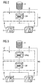
- a plurality of IGMP end-user hosts H are each connected via allocated ports to end-user devices D1 to D3, which are shown as a television, a telephone and a computer.
- Other ports of the hosts H are connected to a common UNI Border DSLAM switch SW, which interfaces a first aggregation network L2.
- This network contains, among other network elements, at least one but preferrably a set of aggregation switches SW ag .
- the UNI Border switches sw are thus connected to the aggregation switches SW ag , which in turn are connected via designated ports to a BRAS router BRAS which is situated logically between the aggregation network L2 and another network L3, whereby L2 is considered to by layer 2 of the OSI model and L3 the third layer.
- An IGMP router R is provided in this further network L3 and is connected to a station VH, preferrably a video head end, adapted to transmitting, processing, receiving and distributing data, in particular multimedia data, over the communications network.
- the arrows in the drawing pointing to the right indicate the transmission of IGMP "Join" Messages from the hosts H via the different network elements shown to the IGMP multicast router R.
- the leftward pointing arrows indicate the forwarding of multicast streams stemming from a service provider and passing via the station VH to the IGMP multicast router R, followe by passing through the various other mentioned network elements to the end-user hosts H.
- IP Multicast router For IPTV distribution in L2/L3 packet based networks, there is an IP multicast router present connected to the Video Head End that VH controls the multicast streams, where each TV channel belongs to one IP Multicast stream, i.e., one group destination address. If such multicast streams need to be carried over an L2 Ethernet network, the group destination address is translated into an Ethernet multicast address.
- a network bridge or Ethernet bridge NB is situated between an IGMP multicast router R and an IGMP host H.
- the network bridge connects multiple network segments (network domains) along the data link layer of the OSI Model. It can take the form of a physical device, such as a network switch, or it may be a virtual device using bridging, as in the case here, where a DSLAM switch SW is connected to the router R and to a plurality of hosts H by means of data links.
- the network bridge is configured to dynamically add or remove port assignments from Multicast Groups by an IGMP "snooping" process, a process in which IGMP messages that are exchanged bewteen an end-user host H and a multicast router R are intercepted.
- IGMP "snooping" process a process in which IGMP messages that are exchanged bewteen an end-user host H and a multicast router R are intercepted.
- the downward pointing arrows indicate the transmission of membership queries, which can be initiated by a network management system.
- the lower upward pointing arrows indicate Join / Leave / Membership Report messages from all hosts H.
- the information related to the viewing habits of the end-user can be retrieved from the DSLAM switch SW near the end-user and correlated with the Multicast Group information to report the end-user viewing habits, for example to a network management system.
- Drawing 3 shows one part of a communications network, comprising a network bridge NB, that is particularly suitable for delivering IPTV services in L2/L3 packet-based networks.
- the IGMP snooping feature can be utilised in all devices that are contained in the L2 network, for example in the L2 aggregation switch SW ag as shown, in this case, forwarding of Ethernet multicast frames is limited to the UNI border DSLAM device, where subscribers that have subscribed to the television or Video on Demand or another multimedia service are connected via hosts H. This allows an effective way of saving resources in the L2 Ethernet network, since the aggregation switch SW ag need not be occupied with the the same said task of the DSLAM switch SW. Where the snooping feature is however enabled at al1 L2 switches including the shown L2 aggregation switch SW ag , the relevant IGMP information nevertheless only needs to be logged and accessed at the UNI Border device.
- the UNI Border DSLAM switch SW is configured to intercept the IGMP messages that are exchanged between the end-user host, such as a subscriber's STB ( S et T op B ox) and an IP multicast router in or next to a video head end.
- the DSLAM switch then adds and deletes entries in its forwarding database, in order to add or delete a single subscriber port to obtain Ethernet frames with a certain Ethernet multicast address.
- all multimedia program channels are delivered to each UNI Border DSLAM switch SW, a procedure which will take place by default if IGMP snooping is not used or deactivated in L2 intermediate aggregation switches SW ag , and the UNI Border DSLAM devices perform IGMP snooping to dynamically add and remove subscriber ports to a certain multicast stream.
- the delivery of selected multimedia channels to the STB is handled directly by the UNI Border DSLAM device and zapping times are expected to be short.
- An alternative lies in manually adding entries to the forwarding database of the intermediate L2 aggregation devices SW ag , in order to determine which Ethernet multicast address should be switched to which ports.
- the relevant information only needs to be logged and accessed at the UNI Border DSLAM switches SW.
- an end-user device such as an STB is still not a member of a multicast group and receives a command from a user to change a TV channel
- the STB sends a "join/leave group" IGMP command into the network.
- the DSLAM connected to the STB will snoop this command and for the corresponding interface it will change its membership to the corresponding IP Multicast Group.
- This information is stored in the DSLAM in Multicast Group Membership logfiles that are retrieved regularly by the network management system.
- the retrieval process can be executed by using SNMP ( S imple N etwork M anagement P rotocol) or another network element management communication protocol.
- a ratings analyser RA preferrably switched between the network management system NMS and the multicast router R, correlates the user identification available in the NMS with the IGMP Snooping log information and the Multicast group/TV channel information (available at either the multicast router or for example at the video head end VH) to provide the viewing habits information, such as user identification, television channel or the time period spent on each television channel.
- Ratings information can be derived by the ratings analyser RA as as follows:
- the "Rating” is considered to be the size of a multimedia viewing or receiving audience relative to the the group of end-users that can possibly access multimedia through the data network.
- the "Share" of the second method described above is the percentage of persons or households using subscribed IPTV IP Multicast Group which are tuned to a specific program or station at a specified time.
- GRPs Gross Rating Points
- TRPs Target Rating Points
- Cume Reach
- Frequency Frequency Distribution
- the user specific information may also be correlated with age, gender and other social statistical data that can be detailed either at the NMS or at an external database of customer information.
- IGMP Version 1 there is no explicit leave process by means of, for example, an explicit "Leave” message.
- the end-user host H does not have to explicitly tell the mulitcast router R of its desire to leave a Multicast Group. Instead, the end-user host H informs the router R of its lack of interest in receiving a multicast stream by not responding to IGMP membership queries from the router R.
- a similar procedure can take place when IGMP Version 2 is used if the "Leave" command is not used by the end-user host. This can happen for several reasons such as the end-user turning off the television or not using the STB to switch between channels.
- the DSLAM switch logs the IGMP requests from the host and this data can be retrieved by the NMS and correlated by the rating analyser to extract useful data such as the multimedia viewing habits of the user.
- One scenario that may cause ratings measurements to be less precise is if 2 or more PUTs or HUTs ( p ersons u sing t elevision or h ouseholds u sing t elevision) are independently watching the same channel and are served by a common end-user host.
- the DSLAM switch will record only 1 IGMP "Join” message and the ratings analyzer RA counts only 1 television channel viewer. This can be remedied by configuring the STB to repeatedly send a "Join" command to the DSLAM switch when one or more persons are using the same program passed through it, even if the desired channel is already present at the STB, so that the 2 PUTs would be handled as giving 2 seperate "Join” commands.
Priority Applications (2)
| Application Number | Priority Date | Filing Date | Title |
|---|---|---|---|
| EP05026086A EP1793552A1 (de) | 2005-11-30 | 2005-11-30 | Kommunikationsnetz und Verfahren zum Auffinden von Benutzerinformationen |
| PCT/EP2006/009942 WO2007062718A1 (en) | 2005-11-30 | 2006-10-14 | Communications network and method for retrieving end-user information |
Applications Claiming Priority (1)
| Application Number | Priority Date | Filing Date | Title |
|---|---|---|---|
| EP05026086A EP1793552A1 (de) | 2005-11-30 | 2005-11-30 | Kommunikationsnetz und Verfahren zum Auffinden von Benutzerinformationen |
Publications (1)
| Publication Number | Publication Date |
|---|---|
| EP1793552A1 true EP1793552A1 (de) | 2007-06-06 |
Family
ID=36263907
Family Applications (1)
| Application Number | Title | Priority Date | Filing Date |
|---|---|---|---|
| EP05026086A Withdrawn EP1793552A1 (de) | 2005-11-30 | 2005-11-30 | Kommunikationsnetz und Verfahren zum Auffinden von Benutzerinformationen |
Country Status (2)
| Country | Link |
|---|---|
| EP (1) | EP1793552A1 (de) |
| WO (1) | WO2007062718A1 (de) |
Families Citing this family (1)
| Publication number | Priority date | Publication date | Assignee | Title |
|---|---|---|---|---|
| US8495428B2 (en) | 2009-06-30 | 2013-07-23 | International Business Machines Corporation | Quality of service management of end user devices in an end user network |
Citations (3)
| Publication number | Priority date | Publication date | Assignee | Title |
|---|---|---|---|---|
| EP1079658A2 (de) * | 1999-08-20 | 2001-02-28 | Texas Instruments Incorporated | Elementverwaltungssystem für einen DSL-Zugriffsmultiplexer |
| EP1395079A2 (de) * | 2002-08-26 | 2004-03-03 | Alcatel | DSLAM-bereitgestellte Funktionalität zur Speicherung von Informationen |
| US20040163101A1 (en) * | 1997-01-06 | 2004-08-19 | Swix Scott R. | Method and system for providing targeted advertisements |
-
2005
- 2005-11-30 EP EP05026086A patent/EP1793552A1/de not_active Withdrawn
-
2006
- 2006-10-14 WO PCT/EP2006/009942 patent/WO2007062718A1/en active Application Filing
Patent Citations (3)
| Publication number | Priority date | Publication date | Assignee | Title |
|---|---|---|---|---|
| US20040163101A1 (en) * | 1997-01-06 | 2004-08-19 | Swix Scott R. | Method and system for providing targeted advertisements |
| EP1079658A2 (de) * | 1999-08-20 | 2001-02-28 | Texas Instruments Incorporated | Elementverwaltungssystem für einen DSL-Zugriffsmultiplexer |
| EP1395079A2 (de) * | 2002-08-26 | 2004-03-03 | Alcatel | DSLAM-bereitgestellte Funktionalität zur Speicherung von Informationen |
Also Published As
| Publication number | Publication date |
|---|---|
| WO2007062718A1 (en) | 2007-06-07 |
Similar Documents
| Publication | Publication Date | Title |
|---|---|---|
| EP1949688B1 (de) | Automatischer kanalwechsel in einem geschalteten digitalen videosystem | |
| US7672233B2 (en) | Traffic management for a passive optical network terminal | |
| US8018963B2 (en) | Systems for flexible wireless channel association | |
| US7742407B2 (en) | Quality of service management in a switched digital video environment | |
| CA2663704C (en) | Bandwidth management in each network device in a switched digital video environment | |
| EP2005745B1 (de) | Lieferung von abonnementdiensten an roaming-nutzer über eine kopfstelle | |
| US20070107023A1 (en) | Channel changes between services with differing bandwidth in a switched digital video system | |
| CN101656872B (zh) | 一种减少网络电视频道切换时延的方法和系统 | |
| WO2001055912A1 (en) | Method and apparatus for client-side authentication and stream selection in a content distribution system | |
| US7549160B1 (en) | Method and system for authenticated access to internet protocol (IP) multicast traffic | |
| EP2351300B1 (de) | Verfahren und system zum herstellen von digitalmedienströmen | |
| US20040221029A1 (en) | Method for selecting a resource to provide a requested service in a multicasting environment | |
| US20130232231A1 (en) | Management of the transmission of data streams over multiple networks | |
| EP2164225B1 (de) | Verfahren und System zur Datenverteilung | |
| EP1793552A1 (de) | Kommunikationsnetz und Verfahren zum Auffinden von Benutzerinformationen | |
| EP2260612B1 (de) | Bandbreitensignalisierung | |
| CN101715118B (zh) | 视频点播服务的流量管理的方法和系统 | |
| US20230171121A1 (en) | Network-based end-to-end low latency docsis | |
| WO2008092250A1 (en) | Cooperative system and method for duplicating and delivering media streams in a distributed manner. | |
| US8874796B1 (en) | Techniques for using a general query to circumvent specific query response failure in an IGMP system | |
| Huijuan et al. | Improvement Approach of IPTV Bearer Network |
Legal Events
| Date | Code | Title | Description |
|---|---|---|---|
| PUAI | Public reference made under article 153(3) epc to a published international application that has entered the european phase |
Free format text: ORIGINAL CODE: 0009012 |
|
| AK | Designated contracting states |
Kind code of ref document: A1 Designated state(s): AT BE BG CH CY CZ DE DK EE ES FI FR GB GR HU IE IS IT LI LT LU LV MC NL PL PT RO SE SI SK TR |
|
| AX | Request for extension of the european patent |
Extension state: AL BA HR MK YU |
|
| RAP1 | Party data changed (applicant data changed or rights of an application transferred) |
Owner name: NOKIA SIEMENS NETWORKS GMBH & CO. KG |
|
| STAA | Information on the status of an ep patent application or granted ep patent |
Free format text: STATUS: THE APPLICATION HAS BEEN WITHDRAWN |
|
| RAP3 | Party data changed (applicant data changed or rights of an application transferred) |
Owner name: NOKIA SIEMENS NETWORKS S.P.A. |
|
| 18W | Application withdrawn |
Effective date: 20071030 |