EP1793297B1 - A method and system for controlling sets of collinear control moment gyroscopes - Google Patents
A method and system for controlling sets of collinear control moment gyroscopes Download PDFInfo
- Publication number
- EP1793297B1 EP1793297B1 EP06124900A EP06124900A EP1793297B1 EP 1793297 B1 EP1793297 B1 EP 1793297B1 EP 06124900 A EP06124900 A EP 06124900A EP 06124900 A EP06124900 A EP 06124900A EP 1793297 B1 EP1793297 B1 EP 1793297B1
- Authority
- EP
- European Patent Office
- Prior art keywords
- momentum
- disc
- cmgs
- torque
- collinear
- Prior art date
- Legal status (The legal status is an assumption and is not a legal conclusion. Google has not performed a legal analysis and makes no representation as to the accuracy of the status listed.)
- Active
Links
- 238000000034 method Methods 0.000 title claims description 13
- 238000011967 cystometrography Methods 0.000 claims description 92
- 239000013598 vector Substances 0.000 description 20
- 239000011159 matrix material Substances 0.000 description 12
- 238000013459 approach Methods 0.000 description 7
- 230000007812 deficiency Effects 0.000 description 4
- 230000001419 dependent effect Effects 0.000 description 2
- 238000010586 diagram Methods 0.000 description 1
- 230000010354 integration Effects 0.000 description 1
- 238000005192 partition Methods 0.000 description 1
Images

Classifications
-
- B—PERFORMING OPERATIONS; TRANSPORTING
- B64—AIRCRAFT; AVIATION; COSMONAUTICS
- B64G—COSMONAUTICS; VEHICLES OR EQUIPMENT THEREFOR
- B64G1/00—Cosmonautic vehicles
- B64G1/22—Parts of, or equipment specially adapted for fitting in or to, cosmonautic vehicles
- B64G1/24—Guiding or controlling apparatus, e.g. for attitude control
- B64G1/28—Guiding or controlling apparatus, e.g. for attitude control using inertia or gyro effect
- B64G1/286—Guiding or controlling apparatus, e.g. for attitude control using inertia or gyro effect using control momentum gyroscopes (CMGs)
-
- B—PERFORMING OPERATIONS; TRANSPORTING
- B64—AIRCRAFT; AVIATION; COSMONAUTICS
- B64G—COSMONAUTICS; VEHICLES OR EQUIPMENT THEREFOR
- B64G1/00—Cosmonautic vehicles
- B64G1/22—Parts of, or equipment specially adapted for fitting in or to, cosmonautic vehicles
- B64G1/24—Guiding or controlling apparatus, e.g. for attitude control
- B64G1/244—Spacecraft control systems
Definitions
- This invention relates to the field of spacecraft vehicle control and, more specifically, to a method and system for controlling sets of collinear control moment gyroscopes.
- a CMG typically comprises a flywheel with a fixed or variable spin rate mounted to a gimbal assembly.
- the spin axis of the CMG can be tilted by moving the CMG using the gimbal assembly. This motion produces a gyroscopic torque orthogonal to the spin axis and gimbal axis.
- a CMG array including a minimum of three CMGs may be arranged such that each CMG in the CMG array imparts torque about a linearly independent axis.
- additional CMGs are provided for redundancy purposes and to assist with singularity avoidance, A singularity can occur when the momentum vectors of the CMGs line up such that one or more components of the requested torque can not be provided. Rather than just ensuring that provided torque does not go to zero, this invention guarantees that provided torque equals requested torque, whenever requested torque values stay below some threshold.
- A is a 3xn Jacobian matrix
- ⁇ is a nxl army of gimbal rates for the n gimbals
- ⁇ is a 3xl array of torque components to be imparted to the spacecraft
- a second approach is to limit the CMG array's momentum output to a smaller area within a momentum envelope.
- the momentum envelope is the momentum provided in all possible combinations of the CMGs in the CMG array.
- singularities can be avoided depending on the CMG arrangement.
- this approach wastes potential torque and results in systems that are larger and heavier than needed.
- FR2826470A , WO9947419A and EP1002716A all disclose satellite attitude control systems using sets of CMGs wherein a repartition of total torque to the sets of CMGs and a calculation of required gimbal movement to produce the allocated torque is carried out to generate an attitude trajectory that avoids singularities.
- the invention consists in a method for controlling the singularity-free movement of two or more sets of collinear control moment gyroscopes, (CMGs,) in an array of CMGs in a spacecraft comprising:
- the invention consists in a control system of a spacecraft for controlling singularity-free movement of two or more sets of collinear control moment gyroscopes, CMGs, the control system comprising:
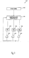
- FIG. 1 is a block diagram illustrating an exemplary CMG control system in accordance with an exemplary embodiment of the present invention
- FIG. 2 illustrates momentum vectors for three CMGs having two independent gimbal angles
- FIG. 3 illustrates momentum ellipses in relation to annular regions formed by torque boundaries that avoid singularities
- FIG. 4a and 4b illustrate momentum ellipses for different solutions that maximize the ellipses in an annular region
- FIG. 5 is a flowchart illustrating a method for maneuvering a spacecraft in accordance with an exemplary embodiment of the present invention.
- FIG. 1 An exemplary control system 100 for implementing the present invention is illustrated in FIG. 1 .
- the components of the control system 100 are known in the art and can be assembled in different ways using different processors, software, controllers, sensors, and the like. Additionally, various computational functionalities that are typically provided by one part of the system can instead be provided by another part.
- the system 100 as shown in FIG. 1 includes parts that are pertinent to the discussion of the present invention and the system 100 may include other elements or systems that might be provided in a control system and which are well known and not shown in FIG. 1 .
- the control system 100 includes an attitude control system 102 coupled to a momentum actuator control processor 104.
- CMGs 106 are coupled the momentum actuator control processor 104.
- Associated with each CMG 106 are one or more CMG sensor 108 for providing information concerning the state of the CMG 106 to the control system 100.
- Control system 100 in one embodiment, is mounted on a spacecraft such as an orbiting satellite.
- Attitude control system 102 controls the positioning of a spacecraft.
- the attitude control system 102 receives data concerning a desired spacecraft maneuver and determines an appropriate torque command to complete the desired maneuver.
- the torque commands can be presented to the momentum actuator control processor 104.
- the momentum actuator control processor 104 in response to the torque commands, can calculate the gimbal rates necessary to produce the commanded torque. Additionally, the momentum actuator control processor 104 calculates gimbal movement from a momentum path determined by a steering law.
- the momentum actuator control processor 104 based on these calculations, provides the necessary commands to the CMGs 106 such that the CMG movement produces the commanded torque and, in accordance with the teachings of the present invention, provides the torque while avoiding singularities. This can be accomplished, in one exemplary embodiment, by changing the gimbal angles of the CMGs at a certain gimbal angle rate.
- a single-gimbal CMG has constant momentum magnitude, and rotates about one axis.
- the constant gimbal axis of the i th CMG in a set of CMGs can be denoted with unit vector p i ⁇ R 3
- the momentum vector of the i th CMG in a set of CMGs can be denoted by vector h i ⁇ R 3
- the gimbal angle of the i th CMG will be denoted by ⁇ i .
- One way to arrange CMGs and achieve full attitude control of a spacecraft is to partition multiple CMGs into two or more sets of collinear CMGs.
- Each CMG in a set of collinear CMGs shares the same gimbal axis direction, but each set of collinear CMGs can have an arbitrary gimbal-axis orientation.
- n CMGs are partitioned into k sets, S k, with unit vectors ⁇ p 1 , p 2 , ... , p k ⁇ different from each other.
- h disc ⁇ 1 ⁇ i ⁇ S 1 ⁇ h i
- p 1 ′ * ⁇ h disc ⁇ 1 0
- h disc ⁇ 2 ⁇ i ⁇ S 2 ⁇ h i
- p 2 ′ * ⁇ h disc ⁇ 2 0
- ⁇ h disc k ⁇ i ⁇ S k ⁇ h i
- h i h i • h disc j ⁇ h disc j ⁇ ⁇ h disc j ⁇ h disc j ⁇ + h i • p j ⁇ ⁇ h disc j ⁇ h disc j ⁇ ⁇ p j ⁇ ⁇ h disc j ⁇ h disc j ⁇
- ⁇ disc j p j ⁇ h disc j ⁇ h disc j ⁇ , h disc j ⁇ h disc j ⁇ ⁇ 0 1 - 1 0 ⁇ p j ⁇ h disc j ⁇ h disc j ⁇ , h disc j ⁇ h disc j ⁇ ⁇ ⁇ t ⁇ S j h i ⁇ ⁇ i
- ⁇ disc j lies in a two-dimensional plane, only two of the gimbal rates, i , with i ⁇ S j , need to be independent. Therefor a gimbal controller can gang, or couple, the gimbals in a way that leaves two independent variables.
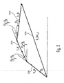
- FIG. 2 illustrates momentum vectors for a set of collinear CMGs.
- CMG a provides a first momentum vector 202 (h ja ) and CMG b provides a second momentum vector 204 (b jb ).
- the gimbal rate is dependent on the gimbal rates of CMG a and CMG b
- CMG c provides a third momentum vector 206 (h jc ).
- the total momentum vector 208 is the sum of the first momentum vector 202, the second momentum vector 204 and the third momentum vector 206.
- CMG c has its gimbal angle dependent on the gimbal angles for CMG a and CMG b .
- h disc j needs to lie in an annulus described by: 2 ⁇ A ⁇ ⁇ h disc j ⁇ ⁇ ⁇ h jc ⁇ + ⁇ h ja ⁇ + ⁇ h jb ⁇ 2 - 2 ⁇ A 2
- L j I - p j * p j ⁇ ⁇ * M j when M j is any 3-by-3 matrix.
- ⁇ ji The values of ⁇ ji can be chosen to maximize the amount of torque available within any given momentum sphere.
- Eqn. 24 shows how to distribute that torque amongst the various discs.
- the ⁇ ji should be chosen to ensure that each h disc j lies in its appropriate annulus when total momentum lies in the largest possible ball, ⁇ h ⁇ ⁇ f ( A ).
- Eqns. 35-37 indicate that h disc j lies in an ellipse, with center determined by ⁇ ji , when ⁇ h ⁇ ⁇ f ( A ).
- the values of ⁇ ji are chosen to maximize the size of the h disc j ellipses, which lie between the inner and outer radii of the corresponding annuli.
- h disc 1 L 1 ⁇ L 1 + L 2 - 1 ⁇ h + ⁇ p 1 ⁇ p 2
- h disc 2 L 2 ⁇ L 1 + L 2 - 1 ⁇ h - ⁇ p 1 ⁇ p 2
- the value of ⁇ can be chosen to maximize the torque that is available within any given size momentum ball.
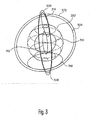
- FIG. 3 illustrates a first outer boundary 306 and a second outer boundary 302 for h disk1 and h disk2 respectively.
- the first outer boundary 306 and the second outer boundary 302 represent the maximum achievable momentum for hdisk1 and h disk2 .
- the first outer boundary 306 and the second outer boundary 302, in the exemplary embodiment shown in FIG. 3 are circular boundaries with a radius r 2 (A min ). Since there is a possibility of the existence of a singularity (or insufficient torque, where ⁇ A MIN ⁇ ) at the maximum momentum, a smaller momentum boundary in which to operate the CMGs can be chosen, which guarantees some larger torque level (where ⁇ >A ⁇ ).
- a first reduced maximum boundary 308 and a second reduced maximum boundary 304 can be selected as the maximum momentum for each of the two discs.
- the radius of the first reduced maximum boundary 308 and a second reduced maximum boundary 304 is r 2 (A), where r 2 (A) ⁇ r 2 (A min ).
- first increased minimum boundary 312, and a second increased minimum boundary 310 can be defined.
- the radius of the first increased minimum boundary 312 and the second increased minimum boundary 310 can be denoted as r 1 (A).
- First reduced maximum boundary 308 and first increased minimum boundary 312 define an annulus for h disk1 and the second reduced maximum boundary 304 and the second increased minimum boundary 310 define an annulus for h disk2 .
- a first ellipse 314 lies within the annulus defined by the first reduced maximum boundary 308 and first increased minimum boundary 312 and a second ellipse 316 lies within the annulus defined by the second reduced maximum boundary 304 and the second increased minimum boundary 310.
- sphere 320 is the momentum sphere formed by the combination of first ellipse 314 and second ellipse 316.
- ⁇ ( A ) arg ⁇ max ⁇ f A s . t . r 1 A ⁇ ⁇ h y h z 2 + ⁇ ⁇ ⁇ r 2 A & r 1 A ⁇ ⁇ h x h z 2 - ⁇ ⁇ ⁇ r 2 A for all ⁇ [ h x h y h z ] ⁇ ⁇ f A
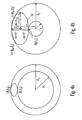
- FIG. 4a illustrates a first ellipse 402 inside a first annular region 404 where 2r 1 (A)> r 2 (A).
- FIG. 4b illustrates a second ellipse 406 inside a second annular region 408 where 2r 1 (A) ⁇ r 2 (A).
- Solution 1 can be used for the situation depicted in FIG. 4a and solution 2 can be used for the situation depicted in FIG. 4b .
- a ⁇ ⁇ h i ⁇ represents the maximum value of A after a failure.
- FIG. 5 is a flowchart of an exemplary method for controlling sets of collinear CMGs.
- a first step, step 502 an offset value for each set of CMGs is determined.
- the offset value determines the maximum momentum ellipse for a set of CMGs that is fully within an annular region derived from the total momentum available from all sets of CMGs.
- the offset value can be determined using Eqn. 73.
- a maneuvering command to rotate spacecraft orientation is received.
- the maneuvering command is sent from a ground control station to the attitude control system 102 of the spacecraft
- the maneuvering command may be generated by the spacecraft based, for example, on a preplanned movement schedule.
- the torque required for each set of CMGs is determined in step 506.
- the needed torque for all sets of collinear CMGs to provide the required maneuver is determined.
- the total torque needed is split into the individual torque required for each set of CMGs which is determined using Eqn. 24.
- the momentum needed to maneuver the spacecraft can be determined and allocated between each set of CMGs. Torque can then be calculated by taking the derivative of the momentum. These calculations can be done at the attitude control system 102.
- step 510 gimbal rates for each CMG in a set of CMGs are determined.
- the gimbal rates can be determined by Eqns. 27-28.
- the gimbal rates can be determined by the momentum actuator control processor.
- step 512 the gimbals for each of the collinear CMGs for each set of collinear CMGs are then moved to provide the proper momentum.
Description
- This invention relates to the field of spacecraft vehicle control and, more specifically, to a method and system for controlling sets of collinear control moment gyroscopes.
- In order to control the attitude of a spacecraft, various rotating inertia members can be used. One such inertia member is a control moment gyroscope (CMG). A CMG typically comprises a flywheel with a fixed or variable spin rate mounted to a gimbal assembly. The spin axis of the CMG can be tilted by moving the CMG using the gimbal assembly. This motion produces a gyroscopic torque orthogonal to the spin axis and gimbal axis.
- To achieve full attitude control of a spacecraft, a CMG array, including a minimum of three CMGs may be arranged such that each CMG in the CMG array imparts torque about a linearly independent axis. Typically, additional CMGs are provided for redundancy purposes and to assist with singularity avoidance, A singularity can occur when the momentum vectors of the CMGs line up such that one or more components of the requested torque can not be provided. Rather than just ensuring that provided torque does not go to zero, this invention guarantees that provided torque equals requested torque, whenever requested torque values stay below some threshold.
- Several different techniques have been developed to avoid singularities, In one method it is first noted that a Jacobian matrix A maps the CMG gimbal rates into a three dimensional array torque:

where A is a 3xn Jacobian matrix, ω is a nxl army of gimbal rates for the n gimbals, and τ is a 3xl array of torque components to be imparted to the spacecraft, From the above equation and with a known torque command, τ, the individual gimbal rates for each CMG can be calculated. Using the known Moore-Penrose pseudoinverse to invert the Jacobian matrix, a set of possible gimbal rates is:
- As discussed previously, inherent in the use of CMGs is the possibility that the CMGs' momentum vectors may line up in such a way that a singularity condition is cached. Mathematically, singularities can occur when the eigenvalues of AAT approach zero, causing (AAT)-1 to approach infinity. Equivalently, singularities occur when the determinant of the matrix AAT is equal to zero (expressed algebraically as det (AAT) =0). In the case of a 3xn matrix A, this is equivalent to the rank of the matrix AAT being two or less.
- Different approaches have been devised to avoid singularities in the movement of CMGs, In one approach, to ensure that (AAT)-1 is never zero, (AAT)-1 is replaced by (AAT + εI)-1 where I is the identity matrix and is a small number. The use of a positive ensures that det (AAT + εI)-1 never becomes 0.
- While useful in some instances, a drawback to this approach is that it changes the gimbal rate calculation. In the case of the Jacobian A, the use of the pseudoinverse means that gimbal rates are no longer exactly mapped into the commanded torques because of the error introduces. This resulting error steers the spacecraft in the wrong direction and can introduce significant, undesired torque, especially near the singularity.
- A second approach is to limit the CMG array's momentum output to a smaller area within a momentum envelope. The momentum envelope is the momentum provided in all possible combinations of the CMGs in the CMG array. In one exemplary embodiment, depending on the CMG arrangement, by operating within one-third or less of the total momentum envelopes, singularities can be avoided. However, this approach wastes potential torque and results in systems that are larger and heavier than needed.
-
FR2826470A WO9947419A EP1002716A all disclose satellite attitude control systems using sets of CMGs wherein a repartition of total torque to the sets of CMGs and a calculation of required gimbal movement to produce the allocated torque is carried out to generate an attitude trajectory that avoids singularities. - In view of the foregoing, it is desirable to provide a method for controlling sets of collinear CMGs that addresses one or more of the foregoing deficiencies or other deficiencies not implicitly or expressly described. It is also desirable to provide a system for controlling sets of collinear CMGs that addresses one or more of the foregoing deficiencies or other deficiencies not implicitly or expressly described. Furthermore, other desirable factors and characteristics of the present invention will become apparent from the subsequent detailed description and the appended claims, taken in conjunction with the accompanying drawings and the foregoing technical field and background.
- In a first aspect, the invention consists in a method for controlling the singularity-free movement of two or more sets of collinear control moment gyroscopes, (CMGs,) in an array of CMGs in a spacecraft comprising:
- determining an offset for each set of the two or more sets of collinear CMGs that guarantees at least a minimum amount of three dimensional torque without using an attitude trajectory of the spacecraft;
- receiving a command to adjust an orientation of the spacecraft;
- determining a total torque needed to adjust the orientation of the spacecraft based at least in part on the minimum amount of three dimensional torque and the command;
- allocating the total torque among to produce an allocated torque for each set of the two or more sets of collinear CMGs; and
- calculating a required gimbal movement for each set of collinear the CMGs in the two or more sets of collinear CMGs from the allocated torque in order to fulfill the command.
- In a second aspect the invention consists in a control system of a spacecraft for controlling singularity-free movement of two or more sets of collinear control moment gyroscopes, CMGs, the control system comprising:
- an attitude control system configured to:
- receive a command to adjust an orientation of the spacecraft;
- determine an offset for a momentum ellipse for each of the two or more sets of collinear CMGs that guarantees at least a minimum amount of three dimensional torque without using an attitude trajectory of the spacecraft;
- determine a momentum needed from the two or more sets of collinear CMGs to adjust the orientation of the spacecraft, based at least in part on the minimum amount of three dimensional torque and the command;
- calculate a total torque needed in order to fulfill the command by taking the derivative of the momentum; and
- a momentum actuator control processor coupled to the attitude control system, the momentum actuator control processor configured to calculate a required gimbal movement for each set of collinear CMGs in each of the two or more sets of collinear CMGs from the allocated total torque.
- The present invention will hereinafter be described in conjunction with the following drawing figures, wherein like numerals denote like elements, and:
-
FIG. 1 is a block diagram illustrating an exemplary CMG control system in accordance with an exemplary embodiment of the present invention; -
FIG. 2 illustrates momentum vectors for three CMGs having two independent gimbal angles; -
FIG. 3 illustrates momentum ellipses in relation to annular regions formed by torque boundaries that avoid singularities; -
FIG. 4a and 4b illustrate momentum ellipses for different solutions that maximize the ellipses in an annular region; and -
FIG. 5 is a flowchart illustrating a method for maneuvering a spacecraft in accordance with an exemplary embodiment of the present invention. - The following detailed description is merely exemplary in nature and is not intended to limit the invention or the application and uses of the invention. Furthermore, there is no intention to be bound by any expressed or implied theory presented in the preceding technical field, background, brief summary or the following detailed description,
- An
exemplary control system 100 for implementing the present invention is illustrated inFIG. 1 . The components of thecontrol system 100 are known in the art and can be assembled in different ways using different processors, software, controllers, sensors, and the like. Additionally, various computational functionalities that are typically provided by one part of the system can instead be provided by another part. Thesystem 100 as shown inFIG. 1 includes parts that are pertinent to the discussion of the present invention and thesystem 100 may include other elements or systems that might be provided in a control system and which are well known and not shown inFIG. 1 . - The
control system 100 includes anattitude control system 102 coupled to a momentumactuator control processor 104.CMGs 106 are coupled the momentumactuator control processor 104. Associated with eachCMG 106 are one ormore CMG sensor 108 for providing information concerning the state of theCMG 106 to thecontrol system 100.Control system 100, in one embodiment, is mounted on a spacecraft such as an orbiting satellite. -
Attitude control system 102 controls the positioning of a spacecraft. Theattitude control system 102 receives data concerning a desired spacecraft maneuver and determines an appropriate torque command to complete the desired maneuver. The torque commands can be presented to the momentumactuator control processor 104. The momentumactuator control processor 104, in response to the torque commands, can calculate the gimbal rates necessary to produce the commanded torque. Additionally, the momentumactuator control processor 104 calculates gimbal movement from a momentum path determined by a steering law. The momentumactuator control processor 104, based on these calculations, provides the necessary commands to theCMGs 106 such that the CMG movement produces the commanded torque and, in accordance with the teachings of the present invention, provides the torque while avoiding singularities. This can be accomplished, in one exemplary embodiment, by changing the gimbal angles of the CMGs at a certain gimbal angle rate. - A single-gimbal CMG has constant momentum magnitude, and rotates about one axis. The constant gimbal axis of the ith CMG in a set of CMGs can be denoted with unit vector pi ∈ R 3, and the momentum vector of the ith CMG in a set of CMGs can be denoted by vector hi ∈ R 3. The gimbal angle of the ith CMG will be denoted by θ i . Thus:

- The torque of the ith CMG in a set of CMGs can be denoted by the vector ri ∈ R 3:

- The total momentum and torque of a system of n CMGs can be denoted by:


- One way to arrange CMGs and achieve full attitude control of a spacecraft is to partition multiple CMGs into two or more sets of collinear CMGs. Each CMG in a set of collinear CMGs shares the same gimbal axis direction, but each set of collinear CMGs can have an arbitrary gimbal-axis orientation. In one exemplary embodiment, n CMGs are partitioned into k sets, Sk, with unit vectors {p 1 , p 2, ... , pk } different from each other. In an exemplary embodiment, eight (8) CMGs can be partitioned into three (3) sets, with {p 1 , p 2, p 3} different from each other:
S 1 = {1,4,7} p 1 = p 4 = p 7 S 2 = {2,3,8} p 2 = p 5 = p 8 S 3 = {3,6} p 3 = p 6 - Each set of collinear CMGs produces a momentum space confined within a disc or annulus:

- If the largest momentum magnitude of any CMG in a collinear set of CMGs is less than or equal to the sum of the momentum magnitudes of all other CMGs, then the total momentum of that set of collinear CMGs will be a disk, otherwise the total momentum will be an annulus. Therefore, a set of two or more collinear CMGs, where each of the CMGs have equal momentum magnitude, will have its total momentum on a disk, while a collinear set of two CMGs with one CMG having more momentum magnitude than the other, results in the total momentum lying within an annulus whose inner radius is the difference of the two momenta.
- The momentum, hi with i ∈ Sj , of a ith CMG in a set of CMGS can be decomposed into one component in the hdisc
j direction and the rest in the pj × hdiscj direction:
- From Eqn. 4 , and noting that pj × (pj × h disc
j ) = -h discj , torque due to the derivative of momentum is given by:
- Total torque from the total momentum of hdisc
j is given by:
- Combining Eqns. 9 and 10 gives:

- Since τdisc
j lies in a two-dimensional plane, only two of the gimbal rates, i , with i ∈ Sj , need to be independent. Therefor a gimbal controller can gang, or couple, the gimbals in a way that leaves two independent variables. In an exemplary embodiment, if the controller splits Sj into three disjoint subsets, Sj = Sja ∪ Sjb ∪ Sjc where θ̇ i = θ̇ ja for i ∈ Sja , θ̇ i = θ̇ jb for i ∈ Sjb and θ̇ i = (θ̇ ja + θ̇ jb )/2 for i ∈ S jc then the momenta of those three subsets can be expressed as:
-
FIG. 2 illustrates momentum vectors for a set of collinear CMGs. InFIG. 2 , CMGa provides a first momentum vector 202 (hja) and CMGb provides a second momentum vector 204 (bjb). For CMGc, the gimbal rate is dependent on the gimbal rates of CMGa and CMGb, and CMGc, provides a third momentum vector 206 (hjc). Thetotal momentum vector 208 is the sum of thefirst momentum vector 202, thesecond momentum vector 204 and thethird momentum vector 206. In this exemplary embodiment, CMGc, has its gimbal angle dependent on the gimbal angles for CMGa and CMGb. The sum on the right of Eqn. 11, can then be written as:
giving τ discj as:
- Noting that the above 3-by-2 matrix just to the right of the equal sign is orthogonal results in an inverse formula:

- Since sufficient torque capabilities in all directions is desirable, for the above selection of gimbal rate constraints the following bound can be used:

This bound can be used to solve for a torque bound:
This can be expressed as:
- the special case where h disc
j *(hjb - hjc ) = 0, the equation
j ∥ solved for. This indicates that hdiscj needs to lie in an annulus described by:
- To control the sets of CMGs, in one exemplary embodiment, a controller can divide total momentum, h, amongst k individual discs according to the rule:

where α ji = α ij such that
- Since the momentum of hdisc
j is in the plane perpendicular to unit vector p j, one choice for matrix Lj is the projection matrix onto the plane that is perpendicular to pj :
The most general choice for L j can be:
when Mj is any 3-by-3 matrix. The values of α ji can be chosen to maximize the amount of torque available within any given momentum sphere. If each Lj and α ji are constant, then:
- Given a commanded torque, Eqn. 24 shows how to distribute that torque amongst the various discs. Gimbal controllers can take each of the τ disc
j and solve for θ̇ i for all i ∈ S j using the following formula:
- The above 3-by-2 matrix just to the right of the equal sign is orthogonal and provides an inverse formula:


- Given any commanded total torque, τ, Eqn. 27 provides the required gimbal rates, using the additional formulas:

where the small positive constant "coeff" corrects any small errors due to discrete integration. - In the special case where ∥h jb ∥ = ∥hja ∥, then hdiscj *(hjb - hja ) = 0, and

- Examining
FIG. 2 , and noting that in the Eqn. 29, ∥hjb - hja ∥/2 is the distance from the base of a trapezoid to its top, the Pythagorean theorem can be used with the momentum vectors illustrated inFIG. 2 on the two triangular corner of the trapezoid to get:
- This reduces Eqn. 27 to:

- Returning to the general case of Eqn. 27 , if Lf =I- pj * p f and P = [p1 , p2 ,...,pk ] then the annulus in which hdisc
j lies can be expressed as:
and the torque bound is:
- Therefore, whenever total momentum stays within a ball with a momentum radius of f(A), the available torque should be above some threshold; i.e., for any value of A:

- The momentum for each set of CMGs, as discussed previously, lies in an annulus of the form:

Where;

and from Eqn. 20:
- The α ji should be chosen to ensure that each hdisc
j lies in its appropriate annulus when total momentum lies in the largest possible ball, ∥h∥ < f(A). Eqns. 35-37 indicate that hdiscj lies in an ellipse, with center determined by α ji , when ∥h∥ < f(A). For each value of "A", the values of α ji are chosen to maximize the size of the hdiscj ellipses, which lie between the inner and outer radii of the corresponding annuli.
- When there are three sets of collinear CMGs, there are three independent α ji* i.e., (α12, α23, α31) and three ellipses whose origin must be adjusted to allow the ellipses to be as large as possible, while still being inside the three annuli. In embodiments where there are two sets of collinear CMGs, there is one independent α ji , i.e. α = α12 and two ellipses whose origin must be moved to allow the two ellipses to be as large as possible, while still being inside the two annuli. As f(A) is optimized, the ellipses touch the annuli in two or three places.
- In the exemplary embodiment of two sets of collinear CMGs, the earlier equations reduce to:


where the value of α can be chosen to maximize the torque that is available within any given size momentum ball. - If L 1, L 2 and α are constant, then:


-
FIG. 3 illustrates a firstouter boundary 306 and a secondouter boundary 302 for hdisk1 and hdisk2 respectively. The firstouter boundary 306 and the secondouter boundary 302 represent the maximum achievable momentum for hdisk1 and hdisk2. The firstouter boundary 306 and the secondouter boundary 302, in the exemplary embodiment shown inFIG. 3 , are circular boundaries with a radius r2(Amin). Since there is a possibility of the existence of a singularity (or insufficient torque, where ∥τ∥≥AMIN∥θ̇∥) at the maximum momentum, a smaller momentum boundary in which to operate the CMGs can be chosen, which guarantees some larger torque level (where ∥τ∥>A∥θ̇∥). For example, a first reducedmaximum boundary 308 and a second reducedmaximum boundary 304 can be selected as the maximum momentum for each of the two discs. The radius of the first reducedmaximum boundary 308 and a second reducedmaximum boundary 304 is r2(A), where r2(A) < r2(Amin). - In addition, singularities can exist at or near the origin, O, of each of the two momentum discs. Therefore, a first increased
minimum boundary 312, and a second increasedminimum boundary 310 can be defined. The radius of the first increasedminimum boundary 312 and the second increasedminimum boundary 310 can be denoted as r1(A). First reducedmaximum boundary 308 and first increasedminimum boundary 312 define an annulus for hdisk1 and the second reducedmaximum boundary 304 and the second increasedminimum boundary 310 define an annulus for hdisk2. Afirst ellipse 314 lies within the annulus defined by the first reducedmaximum boundary 308 and first increasedminimum boundary 312 and asecond ellipse 316 lies within the annulus defined by the second reducedmaximum boundary 304 and the second increasedminimum boundary 310. Thefirst ellipse 314 is where the hdisk1 lies and thesecond ellipse 316 is where the hdisk2 lies when ∥h∥=∥h disc1 + h disc2 ∥≤f(A) lies within a sphere of radius f(A). InFig. 3 ,sphere 320 is the momentum sphere formed by the combination offirst ellipse 314 andsecond ellipse 316. - To maximize the radius f(A), which will maximize the momentum for a given size torque limit, "A," an ellipse offset function α(A)is calculated. If the normal vectors, p1 and p2, of the two momentum discs are chosen to be orthogonal, then p 1*p 2 = 0, and the entire system of CMGs can be rotated until those two unit vectors line up with the first two coordinate axes:

This gives
and
This results in two ellipses with each ellipse representing the momentum of a set of CMGs.

- To maximize the size, f(A), of the 3D momentum sphere, the function α(A) needs to be chosen such that it determines the two ellipse centers at±[0;0;α], which will keep each ellipse within its annulus whose inner radius is r1 and outer radius is r2.

- The maximum of f(A) is attained when each ellipse touches both the inner and outer radii of each corresponding annulus. Since each ellipse has a similar structure, the same value of α causes each ellipse to touch both inner and outer radii of its corresponding annulus, For each optimum value of α, the same optimum value would be achieved by changing the sign on α, so only positive values of α are considered. Consider the first ellipse, whose equation is:

or
- The point [x,y,z] =[0,0,r 1(A)] is where an ellipse just touches its annular boundaries at the smallest radius, r 1(A). If the points [0,±y 0,z 0] are where the ellipse just touches its annular boundaries at the largest radius, r 2(A), then the following equations for the values of α(A), f(A), y0 (A) and z0 (A) can be solved, using the known intermediate functions r 1(A) and r 2(A):


- The two solutions of Eqn. 53 are:

- Using these two solutions to solve the remaining three equations gives:
- Solution 1:


- Solution 2: The z 0 = 4*(z 0 -α) solution implies that z 0=4α/3. Subtracting equations 51 and 52 eliminates y 0, leaving:

- Substituting z0=4α/3 into this equation gives:


- In order for the ellipse to be inside the annulus, α>r 1(A). Given α>r 1(A), Eqn. 54 is:

- Substituting Eqn. 63 into Eqn. 62 results in:

- Solving this quadratic equation for f, and keeping the positive solution gives the value of f for solution2:

- Note that for any given value of r 1(A)/r 2(A), both solution 1 and solution 2' will give an ellipse that is tangent to both the inner and outer radius of the annulus, but exactly one of the solutions will give an ellipse that is totally inside the annulus. Setting f solution1(A) = fsolution2 (A) gives r 2(A) = 2r 1(A) where the valid solution switches between solution 1 and
solution 2. For r 2(A) < 2r 1(A), solution 1 gives an ellipse that is inside the annulus. For r 2(A) > 2r 1(A),solution 2 gives an ellipse that is inside the annalus. This is illustrated inFIG. 4a and FIG. 4b. FIG. 4a illustrates a first ellipse 402 inside a first annular region 404 where 2r1(A)> r2(A).FIG. 4b illustrates a second ellipse 406 inside a second annular region 408 where 2r1 (A) < r2(A). Solution 1 can be used for the situation depicted inFIG. 4a andsolution 2 can be used for the situation depicted inFIG. 4b . - To complete the solutions, recall from earlier in this section that:


- In the case where each of the two discs has three collinear CMGs, and all six ∥hi ∥ are equal:


- The maximum value of A with all six ∥hi ∥ equal and or r 1(A)<r 2(A),

- In the case where either or both of the two discs has lost one of its three collinear CMGs, label the lost CMG as ∥hjc ∥ thus:


- A < ∥hi ∥ represents the maximum value of A after a failure.
- In summary, to ensure that available torque is above some threshold, A, whenever total momentum stays within some ball of a given size, f(A):

we need f(A) to be given by:
-
FIG. 5 is a flowchart of an exemplary method for controlling sets of collinear CMGs. In a first step,step 502, an offset value for each set of CMGs is determined. The offset value determines the maximum momentum ellipse for a set of CMGs that is fully within an annular region derived from the total momentum available from all sets of CMGs. In the exemplary embodiment where there are two orthogonal sets of CMGs, with each set containing three CMGs, the offset value can be determined using Eqn. 73. By determining the appropriate ellipse for each set of CMGs, a guaranteed minimum amount of torque can be calculated. - Next, in
step 504, a maneuvering command to rotate spacecraft orientation is received. In one exemplary embodiment, the maneuvering command is sent from a ground control station to theattitude control system 102 of the spacecraft Alternatively, the maneuvering command may be generated by the spacecraft based, for example, on a preplanned movement schedule. - After the maneuvering command is received, the torque required for each set of CMGs is determined in
step 506. In one embodiment, the needed torque for all sets of collinear CMGs to provide the required maneuver is determined. Then, instep 508, the total torque needed is split into the individual torque required for each set of CMGs which is determined using Eqn. 24. Alternatively, the momentum needed to maneuver the spacecraft can be determined and allocated between each set of CMGs. Torque can then be calculated by taking the derivative of the momentum. These calculations can be done at theattitude control system 102. - In
step 510, gimbal rates for each CMG in a set of CMGs are determined, The gimbal rates can be determined by Eqns. 27-28. In one exemplary embodiment, the gimbal rates can be determined by the momentum actuator control processor. - In
step 512, the gimbals for each of the collinear CMGs for each set of collinear CMGs are then moved to provide the proper momentum. - The exemplary embodiment or embodiments described herein are not intended to limit the scope, applicability, or configuration of the invention in any way. Rather, the foregoing detailed description will provide those skilled in the art with a convenient road map for implementing the described embodiment or embodiments. It should be understood that various changes can be made in the function and arrangement of elements without departing from the scope of the invention as set forth in the appended claims and the legal equivalents thereof.
Claims (8)
- A method for controlling the singularity-free movement of two or more sets of collinear control moment gyroscopes, CMGs, (106) in an array of CMGs in a spacecraft comprising:determining (502) an offset for a momentum ellipse (316) for each set of the two or more sets of collinear CMGs (106) that guarantees at least a minimum amount of three dimensional torque, without using an attitude trajectory of the spacecraft;receiving (504) a command to adjust an orientation of the spacecraft;determining (506) a total torque needed to adjust the orientation of the spacecraft based at least in part on the minimum amount of three dimensional torque and the command;allocating (508) the total torque among the two or more sets of collinear CMGs; andcalculating (510) a required gimbal movement for each set of collinear CMGs in the two or more sets of collinear CMGs from the allocated torque in order to fulfill the command.
- The method of claim 1, wherein the step of determining (502) an offset further comprises maximizing an ellipse (316) representative of the momentum space in an annular region for one set of the two or more sets of collinear CMGs.
- The method of claim 1, wherein the step of determining (502) an offset further comprises allocating an annular region (304, 310) based on a maximum momentum boundary that avoids the edge of a momentum space and a minimum momentum boundary that avoids a center of the momentum space.
- The method of claim 1, wherein the step of determining (502) an offset further comprises determining a torque bound for a given momentum radius (320).
- The method of claim 1, wherein the step of determining the total torque further comprises:calculating the total torque needed to adjust the orientation of the spacecraft by taking the derivative of a total momentum; anddetermining if the total momentum exceeds an available momentum sphere (320) having a radius.
- A control system of a spacecraft for controlling singularity-free movement of two or more sets of collinear control moment gyroscopes, CMGs, (106), the control system comprising:an attitude control system (102) configured to:receive (504) a command to adjust an orientation of the spacecraft;determine (502) an offset for a momentum ellipse (316) for each of the two or more sets of collinear CMGs that guarantees at least a minimum amount of three dimensional torque without using an attitude trajectory of the spacecraft;determine a momentum needed from the two or more sets of collinear CMGs to adjust the orientation of the spacecraft, based at least in part on the minimum amount of three dimensional torque and the command;calculate (506) a total torque needed in order to fulfill the command by taking the derivative of the momentum; anda momentum actuator control processor (104) coupled to the attitude control system, the momentum actuator control processor configured to calculate a required gimbal movement for each set of collinear CMGs in each of the two or more sets of collinear CMGs from the allocated total torque.
- The system of claim 6, wherein the attitude control system (102) is further configured to allocate the total torque to produce an allocated torque for each set of the two or more sets of collinear CMGs (106).
- The system of claim 6, wherein the attitude control system is further configured to determine if the momentum needed exceeds the momentum available in a momentum sphere (320) having a radius.
Applications Claiming Priority (1)
| Application Number | Priority Date | Filing Date | Title |
|---|---|---|---|
| US11/291,706 US7693619B2 (en) | 2005-11-30 | 2005-11-30 | Method and system for controlling sets of collinear control moment gyroscopes with offset determination without attitude trajectory of spacecraft |
Publications (3)
| Publication Number | Publication Date |
|---|---|
| EP1793297A2 EP1793297A2 (en) | 2007-06-06 |
| EP1793297A3 EP1793297A3 (en) | 2008-09-10 |
| EP1793297B1 true EP1793297B1 (en) | 2010-09-22 |
Family
ID=37866159
Family Applications (1)
| Application Number | Title | Priority Date | Filing Date |
|---|---|---|---|
| EP06124900A Active EP1793297B1 (en) | 2005-11-30 | 2006-11-28 | A method and system for controlling sets of collinear control moment gyroscopes |
Country Status (4)
| Country | Link |
|---|---|
| US (1) | US7693619B2 (en) |
| EP (1) | EP1793297B1 (en) |
| JP (1) | JP5528655B2 (en) |
| DE (1) | DE602006017027D1 (en) |
Families Citing this family (8)
| Publication number | Priority date | Publication date | Assignee | Title |
|---|---|---|---|---|
| US8209070B2 (en) * | 2008-12-17 | 2012-06-26 | Honeywell International Inc. | Methods and systems for efficiently orienting an agile vehicle using a gyroscope array |
| US8014911B2 (en) * | 2009-11-03 | 2011-09-06 | Honeywell International Inc. | Methods and systems for imposing a momentum boundary while reorienting an agile vehicle with control moment gyroscopes |
| CN102063521B (en) * | 2010-10-12 | 2012-07-25 | 北京理工大学 | Design method for configuration-adjustable single-framework control moment gyro system |
| US9061775B2 (en) * | 2012-06-22 | 2015-06-23 | Isaac M. Ross | Method and apparatus for spacecraft attitude control using polynomial interpolation |
| US8880246B1 (en) * | 2012-08-22 | 2014-11-04 | United States Of America As Represented By The Secretary Of The Navy | Method and apparatus for determining spacecraft maneuvers |
| US9567112B1 (en) | 2013-06-27 | 2017-02-14 | The United States Of America, As Represented By The Secretary Of The Navy | Method and apparatus for singularity avoidance for control moment gyroscope (CMG) systems without using null motion |
| KR101853213B1 (en) | 2016-12-28 | 2018-04-27 | 한국항공우주연구원 | Apparatus and method for changing gimbal angle of three control moment gyro |
| CN107084744B (en) * | 2017-03-30 | 2019-12-20 | 北京航天控制仪器研究所 | Inertial platform system gyroscope torquer coefficient calibration method |
Family Cites Families (13)
| Publication number | Priority date | Publication date | Assignee | Title |
|---|---|---|---|---|
| US4504032A (en) * | 1982-03-10 | 1985-03-12 | Rca Corporation | Control of nutation in a spacecraft |
| US6154691A (en) * | 1997-09-02 | 2000-11-28 | Honeywell International Inc. | Orienting a satellite with controlled momentum gyros |
| US6039290A (en) | 1998-03-16 | 2000-03-21 | Honeywell Inc. | Robust singularity avoidance in satellite attitude control |
| US6128556A (en) * | 1998-03-16 | 2000-10-03 | Honeywell International Inc. | CMG control based on angular momentum to control satellite attitude |
| US6131056A (en) * | 1998-03-16 | 2000-10-10 | Honeywell International Inc. | Continuous attitude control that avoids CMG array singularities |
| FR2786283B1 (en) * | 1998-11-19 | 2001-01-26 | Matra Marconi Space France | METHOD AND DEVICE FOR CONTROLLING THE ATTITUDE OF A SATELLITE |
| FR2826470B1 (en) * | 2001-06-26 | 2003-09-19 | Astrium Sas | METHOD AND DEVICE FOR STEERING THE ATTITUDE AND GUIDANCE OF A SATELLITE BY A GYRODYNES CLUSTER |
| US6648274B1 (en) * | 2002-04-12 | 2003-11-18 | David A. Bailey | Virtual reaction wheel array |
| AU2003294218A1 (en) * | 2002-08-28 | 2004-04-23 | Arizona Board Of Regents | Steering logic for control moment gyro system |
| US6766227B2 (en) * | 2002-11-19 | 2004-07-20 | The Boeing Company | Attitude-acquisition methods and systems for controlled spacecraft attitude |
| US6921049B2 (en) * | 2003-11-18 | 2005-07-26 | The Boeing Company | System for counteracting a disturbance in a spacecraft |
| US7246776B2 (en) * | 2004-07-23 | 2007-07-24 | Honeywell International, Inc. | Method and system for CMG array singularity avoidance |
| US7370833B2 (en) | 2005-10-20 | 2008-05-13 | Honeywell International Inc. | Method and system for determining a singularity free momentum path |
-
2005
- 2005-11-30 US US11/291,706 patent/US7693619B2/en active Active
-
2006
- 2006-11-28 DE DE602006017027T patent/DE602006017027D1/en active Active
- 2006-11-28 EP EP06124900A patent/EP1793297B1/en active Active
- 2006-11-30 JP JP2006323060A patent/JP5528655B2/en active Active
Also Published As
| Publication number | Publication date |
|---|---|
| US20070124032A1 (en) | 2007-05-31 |
| EP1793297A3 (en) | 2008-09-10 |
| JP5528655B2 (en) | 2014-06-25 |
| US7693619B2 (en) | 2010-04-06 |
| EP1793297A2 (en) | 2007-06-06 |
| DE602006017027D1 (en) | 2010-11-04 |
| JP2007163476A (en) | 2007-06-28 |
Similar Documents
| Publication | Publication Date | Title |
|---|---|---|
| EP1793297B1 (en) | A method and system for controlling sets of collinear control moment gyroscopes | |
| EP1908686B1 (en) | Hierarchial strategy for singularity avoidance in arrays of control moment gyroscopes | |
| Ford et al. | Singular direction avoidance steering for control-moment gyros | |
| US6917862B2 (en) | Singularity escape/avoidance steering logic for control moment gyro systems | |
| EP1782143B1 (en) | Method and system for optimizing torque in a cmg array | |
| EP1776626B1 (en) | Method and system for cmg array singularity avoidance | |
| US7370833B2 (en) | Method and system for determining a singularity free momentum path | |
| EP3087006B1 (en) | Attitude control for agile satellite applications | |
| EP1749743B1 (en) | A method and system for determining a singularity free momentum path | |
| Mehmood et al. | A maneuverability analysis of a novel hexarotor UAV concept | |
| JP2004535324A5 (en) | ||
| US6360996B1 (en) | Steering control for skewed scissors pair CMG clusters | |
| JPH09328100A (en) | Single axis correction for orbital inclination | |
| EP2316736B1 (en) | Methods and systems for imposing a momentum boundary while reorienting an agile vehicle with control moment gyroscopes | |
| US5646847A (en) | Universal thruster selection logic for spacecraft attitude control | |
| EP4032816A1 (en) | Manipulation method suitable for non-redundant sgcmg group | |
| Chen et al. | Earth escape from a sun-earth halo orbit using unstable manifold and lunar swingbys | |
| Ali et al. | Maximizing the Onboard Capability of the Spacecraft Attitude Control System Based on Optimal Use of Reaction Wheels. | |
| Ashok et al. | Cmg configuration and steering approach for spacecraft rapid maneuvers | |
| Jones et al. | A generalized framework for linearly-constrained singularity-free control moment gyro steering laws | |
| Tekinalp et al. | Gimbal angle restricted control moment gyroscope clusters |
Legal Events
| Date | Code | Title | Description |
|---|---|---|---|
| PUAI | Public reference made under article 153(3) epc to a published international application that has entered the european phase |
Free format text: ORIGINAL CODE: 0009012 |
|
| AK | Designated contracting states |
Kind code of ref document: A2 Designated state(s): AT BE BG CH CY CZ DE DK EE ES FI FR GB GR HU IE IS IT LI LT LU LV MC NL PL PT RO SE SI SK TR |
|
| AX | Request for extension of the european patent |
Extension state: AL BA HR MK YU |
|
| PUAL | Search report despatched |
Free format text: ORIGINAL CODE: 0009013 |
|
| AK | Designated contracting states |
Kind code of ref document: A3 Designated state(s): AT BE BG CH CY CZ DE DK EE ES FI FR GB GR HU IE IS IT LI LT LU LV MC NL PL PT RO SE SI SK TR |
|
| AX | Request for extension of the european patent |
Extension state: AL BA HR MK RS |
|
| RIC1 | Information provided on ipc code assigned before grant |
Ipc: B64G 1/28 20060101ALI20080805BHEP Ipc: G05D 1/00 20060101AFI20070402BHEP |
|
| 17P | Request for examination filed |
Effective date: 20090302 |
|
| 17Q | First examination report despatched |
Effective date: 20090417 |
|
| AKX | Designation fees paid |
Designated state(s): DE FR GB IT |
|
| GRAP | Despatch of communication of intention to grant a patent |
Free format text: ORIGINAL CODE: EPIDOSNIGR1 |
|
| RAP1 | Party data changed (applicant data changed or rights of an application transferred) |
Owner name: HONEYWELL INTERNATIONAL INC. |
|
| GRAS | Grant fee paid |
Free format text: ORIGINAL CODE: EPIDOSNIGR3 |
|
| GRAA | (expected) grant |
Free format text: ORIGINAL CODE: 0009210 |
|
| AK | Designated contracting states |
Kind code of ref document: B1 Designated state(s): DE FR GB IT |
|
| REG | Reference to a national code |
Ref country code: GB Ref legal event code: FG4D |
|
| REF | Corresponds to: |
Ref document number: 602006017027 Country of ref document: DE Date of ref document: 20101104 Kind code of ref document: P |
|
| PG25 | Lapsed in a contracting state [announced via postgrant information from national office to epo] |
Ref country code: IT Free format text: LAPSE BECAUSE OF FAILURE TO SUBMIT A TRANSLATION OF THE DESCRIPTION OR TO PAY THE FEE WITHIN THE PRESCRIBED TIME-LIMIT Effective date: 20100922 |
|
| PLBE | No opposition filed within time limit |
Free format text: ORIGINAL CODE: 0009261 |
|
| STAA | Information on the status of an ep patent application or granted ep patent |
Free format text: STATUS: NO OPPOSITION FILED WITHIN TIME LIMIT |
|
| 26N | No opposition filed |
Effective date: 20110623 |
|
| REG | Reference to a national code |
Ref country code: DE Ref legal event code: R097 Ref document number: 602006017027 Country of ref document: DE Effective date: 20110623 |
|
| PGFP | Annual fee paid to national office [announced via postgrant information from national office to epo] |
Ref country code: GB Payment date: 20121025 Year of fee payment: 7 |
|
| GBPC | Gb: european patent ceased through non-payment of renewal fee |
Effective date: 20131128 |
|
| PG25 | Lapsed in a contracting state [announced via postgrant information from national office to epo] |
Ref country code: GB Free format text: LAPSE BECAUSE OF NON-PAYMENT OF DUE FEES Effective date: 20131128 |
|
| REG | Reference to a national code |
Ref country code: FR Ref legal event code: PLFP Year of fee payment: 10 |
|
| REG | Reference to a national code |
Ref country code: FR Ref legal event code: PLFP Year of fee payment: 11 |
|
| REG | Reference to a national code |
Ref country code: FR Ref legal event code: PLFP Year of fee payment: 12 |
|
| P01 | Opt-out of the competence of the unified patent court (upc) registered |
Effective date: 20230525 |
|
| PGFP | Annual fee paid to national office [announced via postgrant information from national office to epo] |
Ref country code: FR Payment date: 20231123 Year of fee payment: 18 Ref country code: DE Payment date: 20231127 Year of fee payment: 18 |