EP1793158A2 - Led Replacement bulb - Google Patents
Led Replacement bulb Download PDFInfo
- Publication number
- EP1793158A2 EP1793158A2 EP06255618A EP06255618A EP1793158A2 EP 1793158 A2 EP1793158 A2 EP 1793158A2 EP 06255618 A EP06255618 A EP 06255618A EP 06255618 A EP06255618 A EP 06255618A EP 1793158 A2 EP1793158 A2 EP 1793158A2
- Authority
- EP
- European Patent Office
- Prior art keywords
- base
- light bulb
- light
- bulb assembly
- emitting diode
- Prior art date
- Legal status (The legal status is an assumption and is not a legal conclusion. Google has not performed a legal analysis and makes no representation as to the accuracy of the status listed.)
- Withdrawn
Links
Images

Classifications
-
- F—MECHANICAL ENGINEERING; LIGHTING; HEATING; WEAPONS; BLASTING
- F21—LIGHTING
- F21K—NON-ELECTRIC LIGHT SOURCES USING LUMINESCENCE; LIGHT SOURCES USING ELECTROCHEMILUMINESCENCE; LIGHT SOURCES USING CHARGES OF COMBUSTIBLE MATERIAL; LIGHT SOURCES USING SEMICONDUCTOR DEVICES AS LIGHT-GENERATING ELEMENTS; LIGHT SOURCES NOT OTHERWISE PROVIDED FOR
- F21K9/00—Light sources using semiconductor devices as light-generating elements, e.g. using light-emitting diodes [LED] or lasers
- F21K9/20—Light sources comprising attachment means
- F21K9/23—Retrofit light sources for lighting devices with a single fitting for each light source, e.g. for substitution of incandescent lamps with bayonet or threaded fittings
- F21K9/232—Retrofit light sources for lighting devices with a single fitting for each light source, e.g. for substitution of incandescent lamps with bayonet or threaded fittings specially adapted for generating an essentially omnidirectional light distribution, e.g. with a glass bulb
-
- F—MECHANICAL ENGINEERING; LIGHTING; HEATING; WEAPONS; BLASTING
- F21—LIGHTING
- F21Y—INDEXING SCHEME ASSOCIATED WITH SUBCLASSES F21K, F21L, F21S and F21V, RELATING TO THE FORM OR THE KIND OF THE LIGHT SOURCES OR OF THE COLOUR OF THE LIGHT EMITTED
- F21Y2115/00—Light-generating elements of semiconductor light sources
- F21Y2115/10—Light-emitting diodes [LED]
Definitions
- This invention is a replacement light for an incandescent light fixture where the replacement light uses a light emitting diode.
- incandescent light bulbs for providing light.
- incandescent light bulbs have the disadvantage of giving off heat when operating. The incandescent light bulbs thus use extra energy by converting the energy to lost heat.
- Incandescent light bulbs are also susceptible to damage by shaking or impact with the bulb. Damage caused by impact and shaking often causes the need to replace the incandescent light bulb.
- incandescent light bulbs have short life spans causing the need for frequent replacements.
- a replacement bulb for an incandescent light fixture which has increased life span and durability without converting energy to heat is needed.
- a replacement light bulb assembly for use in an incandescent light fixture utilizes a light emitting diode.
- the replacement light bulb assembly includes a base and a light emitting diode (LED).
- the base fits within a typical incandescent light bulb fixture.
- the LED is bonded to the base with a non-conducting material and is electrically connected to the base through a base connector.
- a center post is located generally along the center of the base and is electrically connected to the LED to complete an electrical circuit when the light bulb assembly is placed within an incandescent light bulb fixture.
- the base has a non-conductive filler to electrically isolate the center post from the base.
- a control is connected to the LED to modify the LED output to change the light intensity, duration (such as a flashing light), or color.
- the control can also be used to modify the voltage or current requirements of the light bulb assembly and allow use with both DC current and AC current.
- An external shield or lens, or an internal shield or lens, may be added to the light bulb assembly or directly to the LED to alter the light emitted from the light bulb assembly.
- the replacement light bulb assembly fits within a typical incandescent light bulb fixture.
- Incandescent light bulbs have standard base sizing for common voltage and current ratings of the applications.
- Several variations of the replacement light bulb assembly each having a base corresponding to a typical incandescent light bulb fixture may be available.
- FIG. 1 shows an illustration of a light bulb assembly 10 of the present invention.
- the assembly includes a base 12 and a light emitting diode (LED) 14.
- the LED 14 is electrically connected to the base 12.
- the base 12 fits within a typical incandescent light bulb fixture.
- the base 12 is a screw base and includes threads 16, which correspond to threads in the typical incandescent light bulb fixture, for retention.
- the bulb may include an internal shield or lens 50, which modifies the light characteristics of the LED 14.
- the light bulb assembly 10 may also include an external shield or lens 52 that is bonded to the light bulb assembly 10 or directly to the LED 14 with a bonding agent 54.
- the internal shield 50, external shield 52 and the bonding agent 54 may be translucent or opaque, and may possess optical characteristics, such as, but not limited to, altering the light in ranges outside the human visible spectrum.
- FIG. 2 is a cross-section of the light bulb assembly of the present invention.
- the LED 14 is mounted onto the base 12. As shown, the LED 14 is bonded to the base 12 with a non-conducting material 17. The LED 14 may be mounted or retained on the base 12 by any known means that provide an electrically isolated mounting.
- the LED 14 is electrically connected to the base 12 through a base connector 18.
- the base connector 18 is connected to the LED 14 at one end and a screw contact 21 at the other.
- the center post 20 Located within the base 12 is a center post 20.
- the center post 20 extends generally parallel to an axis A of the base 12 and leads to a base contact 23 of the base 12.
- the center post 20 is electrically connected to the LED 14 at the post connector location 22.
- the base 12 is filled with a non-conductive filler 24 to electrically isolate the center post 20 from the base 12.
- a control 26 is connected to the LED 14 to modify the LED 14 output as desired.
- the control 26 is preferably positioned within the base 12 but may be located in any position convenient to the light bulb assembly 10 where the control 26 can be connected to the LED 14.
- the control 26 may be set at the time of manufacture of the light bulb assembly 10 to modify the LED 14 output as is known in the art.
- the control 26 may modify the light bulb assembly 10 output to change the light intensity, duration (such as a flashing light), or color.
- the control 26 can also be used to modify the voltage or current requirements of the light bulb assembly 10 for use with DC current of AC current applications. During manufacture the control 26 can be set allowing the light bulb assembly 10 to operate in most popular DC current voltage ratings such as 1.5V, 3V, 4.5V, 6V, 9V and 12V.
- the light bulb assembly 10 may also have typical household ratings of 110VAC and 220VAC.
- the control 26 may be set to modify the light bulb assembly 10 to other DC current or AC current settings as well.
- the LED may also be shielded to reduce direct viewing or to modify the direction of the light. Multiple LEDs may be used to increase the light intensity, color, duration (such as flashing), direction and time dependant characteristics when used with control 26.
- the light bulb assembly 10 fits within a typical incandescent light bulb fixture.
- Incandescent light bulbs have standard base sizing for common voltage and current ratings of the applications.
- Several variations of the light bulb assembly 10 each having the base 12, which corresponds to a typical incandescent light bulb fixture, may be available.
- Figure 3 is an illustration of one embodiment of the light bulb assembly 10 of the present invention in a flashlight 28.
- the base 30 is sized to a typical incandescent light bulb base for use in flashlights and corresponds in size to the flashlight bulb fixture 32.
- the control 26 modifies the LED 14 to have typical output for use in a flashlight, a high intensity, white light, and a DC 3V setting.
- the LED 14 can be modified to change the directional nature of the emitted light. Shielding of the LED 14, either with an internal shield 50 or an external shield 52 bonded to the light bulb assembly 10 (as shown in Figure 1), can be used to change the color, direction, dispersion, focus, prevent excessive direct exposure, introduce patterns to be projected, or adjust the light pattern to match the intended device's internal reflective geometry 56.
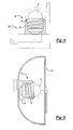
- FIG 4 is an illustration of another embodiment of the light bulb assembly 10 in a night-light 34.
- the base 36 is sized to a typical incandescent light bulb base 38 for use in night-lights.
- the control 26 (shown in Figure 2) modifies the LED 14 to have typical night-light output of a low intensity, yellow light, and an AC 4W or 7W rating.
- FIG. 5 is an illustration of another embodiment of the light bulb assembly 10 in an automotive instrument panel 40.
- a section of an instrument panel 40 is shown.
- the base 42 is sized to a typical incandescent light bulb base 44 for use with the instrument panel 40.
- the control 26 (shown in Figure 2) modifies the LED 14 to have typical instrument panel 40 output of a low intensity, white light, and a DC 12V setting. Alternate embodiments of the light bulb assembly 10 with the control 26 set to modify the LED 14 output to other typical night-light 33, flashlight 28 or instrument panel 40 outputs may be utilized.
Landscapes
- Engineering & Computer Science (AREA)
- Physics & Mathematics (AREA)
- Microelectronics & Electronic Packaging (AREA)
- Optics & Photonics (AREA)
- General Engineering & Computer Science (AREA)
- Fastening Of Light Sources Or Lamp Holders (AREA)
- Non-Portable Lighting Devices Or Systems Thereof (AREA)
- Led Device Packages (AREA)
- Arrangement Of Elements, Cooling, Sealing, Or The Like Of Lighting Devices (AREA)
Abstract
Description
- This invention is a replacement light for an incandescent light fixture where the replacement light uses a light emitting diode.
- Common products such as flashlights, toys, instrument panels, etc. use incandescent light bulbs for providing light. However, incandescent light bulbs have the disadvantage of giving off heat when operating. The incandescent light bulbs thus use extra energy by converting the energy to lost heat. Incandescent light bulbs are also susceptible to damage by shaking or impact with the bulb. Damage caused by impact and shaking often causes the need to replace the incandescent light bulb. In addition, incandescent light bulbs have short life spans causing the need for frequent replacements.
- Because use of incandescent light bulbs is so prevalent any replacement must be able to fit and operate with an incandescent light bulb fixture.
- A replacement bulb for an incandescent light fixture which has increased life span and durability without converting energy to heat is needed.
- A replacement light bulb assembly for use in an incandescent light fixture utilizes a light emitting diode.
- The replacement light bulb assembly includes a base and a light emitting diode (LED). The base fits within a typical incandescent light bulb fixture. The LED is bonded to the base with a non-conducting material and is electrically connected to the base through a base connector. A center post is located generally along the center of the base and is electrically connected to the LED to complete an electrical circuit when the light bulb assembly is placed within an incandescent light bulb fixture. The base has a non-conductive filler to electrically isolate the center post from the base.
- A control is connected to the LED to modify the LED output to change the light intensity, duration (such as a flashing light), or color. The control can also be used to modify the voltage or current requirements of the light bulb assembly and allow use with both DC current and AC current. An external shield or lens, or an internal shield or lens, may be added to the light bulb assembly or directly to the LED to alter the light emitted from the light bulb assembly.
- The replacement light bulb assembly fits within a typical incandescent light bulb fixture. Incandescent light bulbs have standard base sizing for common voltage and current ratings of the applications. Several variations of the replacement light bulb assembly each having a base corresponding to a typical incandescent light bulb fixture may be available.
- These and other features of the present invention can be best understood from the following specification and drawings, the following of which is a brief description.
-
- Figure 1 is an illustration of an embodiment of a light bulb assembly of the present invention.
- Figure 2 is a cross-section of an embodiment of the light bulb assembly of the present invention.
- Figure 3 is an embodiment of the light bulb assembly of the present invention for use in a flashlight.
- Figure 4 is an embodiment of the light bulb assembly of the present invention for use in a night-light.
- Figure 5 is an embodiment of the light bulb assembly of the present invention for use in an automotive instrument panel.
- Figure 1 shows an illustration of a
light bulb assembly 10 of the present invention. The assembly includes abase 12 and a light emitting diode (LED) 14. TheLED 14 is electrically connected to thebase 12. Thebase 12 fits within a typical incandescent light bulb fixture. In the embodiment shown, thebase 12 is a screw base and includesthreads 16, which correspond to threads in the typical incandescent light bulb fixture, for retention. The bulb may include an internal shield orlens 50, which modifies the light characteristics of theLED 14. Thelight bulb assembly 10 may also include an external shield orlens 52 that is bonded to thelight bulb assembly 10 or directly to theLED 14 with abonding agent 54. Theinternal shield 50,external shield 52 and thebonding agent 54 may be translucent or opaque, and may possess optical characteristics, such as, but not limited to, altering the light in ranges outside the human visible spectrum. - Figure 2 is a cross-section of the light bulb assembly of the present invention. The
LED 14 is mounted onto thebase 12. As shown, theLED 14 is bonded to thebase 12 with anon-conducting material 17. TheLED 14 may be mounted or retained on thebase 12 by any known means that provide an electrically isolated mounting. TheLED 14 is electrically connected to thebase 12 through abase connector 18. Thebase connector 18 is connected to theLED 14 at one end and ascrew contact 21 at the other. - Located within the
base 12 is acenter post 20. Thecenter post 20 extends generally parallel to an axis A of thebase 12 and leads to abase contact 23 of thebase 12. Thecenter post 20 is electrically connected to theLED 14 at thepost connector location 22. Thebase 12 is filled with anon-conductive filler 24 to electrically isolate thecenter post 20 from thebase 12. When thelight bulb assembly 10 is assembled into an incandescent light fixture, an electric circuit to theLED 14 is completed through thescrew contact 21 and thebase contact 23. - A
control 26 is connected to theLED 14 to modify theLED 14 output as desired. Thecontrol 26 is preferably positioned within thebase 12 but may be located in any position convenient to thelight bulb assembly 10 where thecontrol 26 can be connected to theLED 14. Thecontrol 26 may be set at the time of manufacture of thelight bulb assembly 10 to modify theLED 14 output as is known in the art. Thecontrol 26 may modify thelight bulb assembly 10 output to change the light intensity, duration (such as a flashing light), or color. Thecontrol 26 can also be used to modify the voltage or current requirements of thelight bulb assembly 10 for use with DC current of AC current applications. During manufacture thecontrol 26 can be set allowing thelight bulb assembly 10 to operate in most popular DC current voltage ratings such as 1.5V, 3V, 4.5V, 6V, 9V and 12V. Thelight bulb assembly 10 may also have typical household ratings of 110VAC and 220VAC. Thecontrol 26 may be set to modify thelight bulb assembly 10 to other DC current or AC current settings as well. The LED may also be shielded to reduce direct viewing or to modify the direction of the light. Multiple LEDs may be used to increase the light intensity, color, duration (such as flashing), direction and time dependant characteristics when used withcontrol 26. - As mentioned above, the
light bulb assembly 10 fits within a typical incandescent light bulb fixture. Incandescent light bulbs have standard base sizing for common voltage and current ratings of the applications. Several variations of thelight bulb assembly 10 each having thebase 12, which corresponds to a typical incandescent light bulb fixture, may be available. For example, Figure 3 is an illustration of one embodiment of thelight bulb assembly 10 of the present invention in aflashlight 28. Thebase 30 is sized to a typical incandescent light bulb base for use in flashlights and corresponds in size to theflashlight bulb fixture 32. The control 26 (shown in Figure 2) modifies theLED 14 to have typical output for use in a flashlight, a high intensity, white light, and a DC 3V setting. TheLED 14 can be modified to change the directional nature of the emitted light. Shielding of theLED 14, either with aninternal shield 50 or anexternal shield 52 bonded to the light bulb assembly 10 (as shown in Figure 1), can be used to change the color, direction, dispersion, focus, prevent excessive direct exposure, introduce patterns to be projected, or adjust the light pattern to match the intended device's internalreflective geometry 56. - Figure 4 is an illustration of another embodiment of the
light bulb assembly 10 in a night-light 34. Thebase 36 is sized to a typical incandescentlight bulb base 38 for use in night-lights. The control 26 (shown in Figure 2) modifies theLED 14 to have typical night-light output of a low intensity, yellow light, and an AC 4W or 7W rating. - Figure 5 is an illustration of another embodiment of the
light bulb assembly 10 in anautomotive instrument panel 40. A section of aninstrument panel 40 is shown. Thebase 42 is sized to a typical incandescentlight bulb base 44 for use with theinstrument panel 40. The control 26 (shown in Figure 2) modifies theLED 14 to havetypical instrument panel 40 output of a low intensity, white light, and a DC 12V setting. Alternate embodiments of thelight bulb assembly 10 with thecontrol 26 set to modify theLED 14 output to other typical night-light 33,flashlight 28 orinstrument panel 40 outputs may be utilized. - Although a preferred embodiment of this invention has been disclosed, a worker of ordinary skill in this art would recognize that certain modifications would come within the scope of this invention. For that reason, the following claims should be studied to determine the true scope and content of this invention.
Claims (20)
- A light bulb assembly (10) comprising:a base (12; 36; 42) to fit with a standard incandescent light fixture;a center post (20) located along an axis (A) of the base (12; 36; 42);a light emitting diode (14) electrically connected to the base (12; 36; 42) and electrically connected to the center post (20).
- A light bulb assembly (10) comprising:a screw base (12; 36; 42) having a screw thread and electrically connected to a light emitting diode (14).
- The light bulb assembly of claim 2, wherein a center post (20) is located along an axis (A) of said screw base (12; 36; 42) and said light emitting diode (14) being electrically connected to said screw base (12; 36; 42) and electrically connected to said center post (20).
- The light bulb assembly of claim 1 or 3, wherein a non-conductive filler (24) is located within the base (12; 36; 42) to electrically isolate the base (12; 36; 42) from the center post (20).
- The light bulb assembly of any preceding claim, wherein said light emitting diode (14) is bonded to the base (12; 36; 42) by a non-conductive material (17).
- The light bulb assembly of any preceding claim, wherein said base (12) is shaped to be received within a flashlight socket (32).
- The light bulb assembly of any of claims 1 to 5, wherein said base (36) is shaped to be received within a night light socket (38).
- The light bulb assembly of any of claims 1 to 5, wherein said base (42) is shaped to be received within an automotive instrument panel socket (44).
- The light bulb assembly of any preceding claim, wherein at least one control (26) is electrically connected to said light emitting diode (14) to modify the output of the light emitting diode (14).
- The light bulb assembly of claim 9, wherein said at least one control (26) is located within the base (12; 36; 42).
- The light bulb assembly of claim 9 or 10, wherein said at least one control (36) modifies the light emitting diode (14) for use with one of a DC current and an AC current.
- The light bulb assembly of any preceding claim, wherein said light emitting diode (14) includes a light emitting diode housing, and said housing has a modification to alter a nature of an emitted light.
- The light bulb assembly of claim 12, wherein said housing modification is one of an internal shield (50) or external shield (52) bonded to the housing.
- The light bulb assembly of claim 12 or 13, wherein said housing modification is translucent.
- A method manufacturing a light bulb comprising:a) providing a base (12; 36; 42) for a standard incandescent light fixture;b) connecting a light emitting diode (14) to the base (12; 36; 42).
- The method of claim 15, wherein said step b) includes providing a center post (20) electrically isolated from the base (12; 36; 42) and electrically connecting the center post (20) to the light emitting diode (14).
- The method of claim 15 or 16, further includesc) connecting a control (36) to the light emitting diode (14) for modifying the output of the light emitting diode (14).
- The method of claim 17, wherein said step c) further includes modifying an intensity of the light emitting diode (14) with the control (36).
- The method of claim 17 or 18, wherein said step c) further includes modifying an output color of the light emitting diode (14) with the control (36).
- The method of any of claims 17 to 19, further includes modifying the light emitting diode (14) for use with one of a DC current and an AC current with the control (36).
Applications Claiming Priority (1)
| Application Number | Priority Date | Filing Date | Title |
|---|---|---|---|
| US11/269,501 US20070103914A1 (en) | 2005-11-08 | 2005-11-08 | LED replacement bulb |
Publications (2)
| Publication Number | Publication Date |
|---|---|
| EP1793158A2 true EP1793158A2 (en) | 2007-06-06 |
| EP1793158A3 EP1793158A3 (en) | 2008-06-25 |
Family
ID=37831981
Family Applications (1)
| Application Number | Title | Priority Date | Filing Date |
|---|---|---|---|
| EP06255618A Withdrawn EP1793158A3 (en) | 2005-11-08 | 2006-11-01 | Led Replacement bulb |
Country Status (8)
| Country | Link |
|---|---|
| US (1) | US20070103914A1 (en) |
| EP (1) | EP1793158A3 (en) |
| JP (1) | JP2007134324A (en) |
| KR (1) | KR100804880B1 (en) |
| CN (1) | CN1963286A (en) |
| MX (1) | MXPA06012627A (en) |
| SG (1) | SG132609A1 (en) |
| TW (1) | TW200719762A (en) |
Families Citing this family (36)
| Publication number | Priority date | Publication date | Assignee | Title |
|---|---|---|---|---|
| US8215815B2 (en) * | 2005-06-07 | 2012-07-10 | Oree, Inc. | Illumination apparatus and methods of forming the same |
| US8128272B2 (en) | 2005-06-07 | 2012-03-06 | Oree, Inc. | Illumination apparatus |
| US8272758B2 (en) | 2005-06-07 | 2012-09-25 | Oree, Inc. | Illumination apparatus and methods of forming the same |
| US8550684B2 (en) * | 2007-12-19 | 2013-10-08 | Oree, Inc. | Waveguide-based packaging structures and methods for discrete lighting elements |
| US7929816B2 (en) | 2007-12-19 | 2011-04-19 | Oree, Inc. | Waveguide sheet containing in-coupling, propagation, and out-coupling regions |
| US8231237B2 (en) * | 2008-03-05 | 2012-07-31 | Oree, Inc. | Sub-assembly and methods for forming the same |
| US8013501B2 (en) * | 2008-06-04 | 2011-09-06 | Forever Bulb, Llc | LED-based light bulb device |
| US8301002B2 (en) | 2008-07-10 | 2012-10-30 | Oree, Inc. | Slim waveguide coupling apparatus and method |
| US8297786B2 (en) | 2008-07-10 | 2012-10-30 | Oree, Inc. | Slim waveguide coupling apparatus and method |
| US20100098377A1 (en) * | 2008-10-16 | 2010-04-22 | Noam Meir | Light confinement using diffusers |
| US20100208470A1 (en) * | 2009-02-10 | 2010-08-19 | Yosi Shani | Overlapping illumination surfaces with reduced linear artifacts |
| NL2002876C2 (en) * | 2009-05-12 | 2010-11-15 | Maretti Holding B V | LED LAMP SYSTEM. |
| US20100320904A1 (en) * | 2009-05-13 | 2010-12-23 | Oree Inc. | LED-Based Replacement Lamps for Incandescent Fixtures |
| KR100987274B1 (en) * | 2009-06-02 | 2010-10-12 | 주식회사 인성전자 | Structure of led lamp |
| WO2010150202A2 (en) | 2009-06-24 | 2010-12-29 | Oree, Advanced Illumination Solutions Inc. | Illumination apparatus with high conversion efficiency and methods of forming the same |
| WO2011056950A1 (en) | 2009-11-04 | 2011-05-12 | Forever Bulb, Llc | Led-based light bulb device with kelvin corrective features |
| US8708519B2 (en) | 2010-05-28 | 2014-04-29 | Alert Stamping & Manufacturing Co., Inc. | LED conversion module for incandescent work light |
| USD631178S1 (en) | 2010-05-28 | 2011-01-18 | Alert Safety Lite Products Co., Inc. | LED lamp |
| USD654602S1 (en) | 2011-04-13 | 2012-02-21 | Forever Bulb, Llc | LED-based light |
| JP2013051029A (en) * | 2011-08-01 | 2013-03-14 | Beat Sonic:Kk | LED lamp |
| USD664684S1 (en) | 2011-09-02 | 2012-07-31 | Forever Bulb, Llc | LED-based light bulb |
| USD664685S1 (en) | 2011-09-07 | 2012-07-31 | Forever Bulb, Llc | LED-based light bulb with power groove |
| US8591072B2 (en) | 2011-11-16 | 2013-11-26 | Oree, Inc. | Illumination apparatus confining light by total internal reflection and methods of forming the same |
| USD691290S1 (en) | 2012-01-05 | 2013-10-08 | Forever Bulb, Llc | LED-based light bulb with multiple stems |
| WO2014006501A1 (en) | 2012-07-03 | 2014-01-09 | Yosi Shani | Planar remote phosphor illumination apparatus |
| USD706959S1 (en) | 2012-10-11 | 2014-06-10 | Forever Bulb, Llc | LED light bulb |
| USD757971S1 (en) | 2014-02-20 | 2016-05-31 | Alert Stamping & Manufacturing Co., Inc. | Handheld work light |
| USD739053S1 (en) | 2014-03-10 | 2015-09-15 | Forever Bulb, Llc | LED light bulb |
| USD739054S1 (en) | 2014-03-10 | 2015-09-15 | Forever Bulb, Llc | LED light bulb |
| USD745708S1 (en) | 2014-03-11 | 2015-12-15 | Forever Bulb, Llc | LED light bulb |
| USD737476S1 (en) | 2014-04-29 | 2015-08-25 | Forever Bulb, Llc | Six internal element LED bulb |
| USD737475S1 (en) | 2014-04-29 | 2015-08-25 | Forever Bulb, Llc | Three internal element LED bulb |
| US9681511B1 (en) | 2016-03-25 | 2017-06-13 | New Energies & Alternative Technologies, Inc. | LED driver circuits |
| US10270359B2 (en) | 2016-03-25 | 2019-04-23 | New Energies & Alternative Technologies, Inc. | Multi-use driver circuits |
| US9681504B1 (en) | 2016-06-14 | 2017-06-13 | New Energies & Alternative Technologies, Inc. | Driver circuits with multiple rectifiers |
| DE102016210673A1 (en) * | 2016-06-15 | 2017-12-21 | Osram Gmbh | Holding device for lamps in vehicle lights and vehicle light |
Family Cites Families (30)
| Publication number | Priority date | Publication date | Assignee | Title |
|---|---|---|---|---|
| US4211955A (en) * | 1978-03-02 | 1980-07-08 | Ray Stephen W | Solid state lamp |
| GB2098714B (en) * | 1980-06-04 | 1984-08-22 | Tranilamp Ltd | Led cluster assembly |
| JPS5974687A (en) * | 1982-10-21 | 1984-04-27 | Idec Izumi Corp | Light emitting diode lamp |
| DE4141980A1 (en) * | 1991-12-19 | 1993-07-01 | Sel Alcatel Ag | High power light emitting diode e.g. for replacing incandescent lamp - has active diode moulded into transparent body together with connections to outer contact points |
| JP3668359B2 (en) * | 1997-06-20 | 2005-07-06 | ウシオ電機株式会社 | Lighting |
| US6965205B2 (en) * | 1997-08-26 | 2005-11-15 | Color Kinetics Incorporated | Light emitting diode based products |
| JP2000021209A (en) * | 1998-06-30 | 2000-01-21 | Elna Co Ltd | Light-emitting diode aggregation lamp |
| TW417842U (en) * | 1998-09-28 | 2001-01-01 | Koninkl Philips Electronics Nv | Lighting system |
| US6218785B1 (en) * | 1999-03-19 | 2001-04-17 | Incerti & Simonini Di Incerti Edda & C. S.N.C. | Low-tension lighting device |
| DE29915140U1 (en) * | 1999-08-29 | 1999-11-25 | Strobl, Thomas, 82541 Münsing | LED spotlight |
| AU2001246355A1 (en) * | 2000-02-11 | 2001-08-20 | Gerhard Abler | Lighting body |
| DE20013775U1 (en) * | 2000-08-07 | 2000-11-30 | Boston Cooltec Corp., Wilmington | Cooling device with universal exchangeable module for cooling |
| DE20013773U1 (en) * | 2000-08-10 | 2000-11-23 | Arand, Wilfried, 14532 Kleinmachnow | Tower for wind turbines with a nacelle arranged in the area of its upper end, to which an external rotor with propeller blades and preferably rotor axis is assigned |
| DE20014813U1 (en) * | 2000-08-26 | 2000-12-14 | Müller, Stefan, 83278 Traunstein | Compact, multi-beam LED light set |
| KR20010000635A (en) * | 2000-10-10 | 2001-01-05 | 이계선 | An electric bulb for a traffic light |
| DE20019874U1 (en) * | 2000-11-23 | 2001-02-08 | BÄ*RO GmbH & Co KG, 42799 Leichlingen | lamp |
| US20020126491A1 (en) * | 2001-03-08 | 2002-09-12 | Chih-Min Chen | LED light bulb with threaded base |
| DE10113526A1 (en) * | 2001-03-20 | 2002-10-02 | Joerg Hohbaum | Lamp for fixing in a low-voltage halogen lamp holder has an integrated standard reflector casing with a high-power LED in/near its focal point. |
| DE20115129U1 (en) * | 2001-09-13 | 2001-11-29 | Lee, Hun Ming, Hsin Chu | Economical and environmentally friendly LED light bulb |
| EP1467414A4 (en) * | 2001-12-29 | 2007-07-11 | Hangzhou Fuyang Xinying Dianzi | A led and led lamp |
| DE10201131A1 (en) * | 2002-01-11 | 2003-08-14 | Pk Electronic Internat Gmbh & | Lamp body has base mounted microprocessor to control individual light sources provided within common bulb |
| US20030185020A1 (en) * | 2002-03-28 | 2003-10-02 | All-Line Inc. | LED bulb for night-light |
| US6796698B2 (en) * | 2002-04-01 | 2004-09-28 | Gelcore, Llc | Light emitting diode-based signal light |
| DE10235699A1 (en) * | 2002-08-03 | 2004-02-19 | Ulo Fahrzeugleuchten Gmbh | Light arrangement, especially for motor vehicles, has base in form of adapter for at least one light emitting diode (LED) light element and current/voltage for at least one LED fed via base |
| US6787999B2 (en) * | 2002-10-03 | 2004-09-07 | Gelcore, Llc | LED-based modular lamp |
| US20040201990A1 (en) * | 2003-04-10 | 2004-10-14 | Meyer William E. | LED lamp |
| DE10321588A1 (en) * | 2003-05-09 | 2004-11-25 | Michael Kaiser | Light especially for a pocket torch, has light diodes in a socket with a fastening compatible with low voltage incandescent lamps and an electronic dc converter |
| JP4236544B2 (en) * | 2003-09-12 | 2009-03-11 | 三洋電機株式会社 | Lighting device |
| JP2005166578A (en) * | 2003-12-05 | 2005-06-23 | Hamai Denkyu Kogyo Kk | Light bulb shaped LED lamp |
| KR100496522B1 (en) | 2005-03-23 | 2005-06-27 | 주식회사 누리플랜 | Led illumination lamp |
-
2005
- 2005-11-08 US US11/269,501 patent/US20070103914A1/en not_active Abandoned
-
2006
- 2006-08-16 TW TW095130097A patent/TW200719762A/en unknown
- 2006-09-15 KR KR1020060089373A patent/KR100804880B1/en not_active Expired - Fee Related
- 2006-10-31 MX MXPA06012627A patent/MXPA06012627A/en not_active Application Discontinuation
- 2006-11-01 EP EP06255618A patent/EP1793158A3/en not_active Withdrawn
- 2006-11-01 JP JP2006297276A patent/JP2007134324A/en active Pending
- 2006-11-07 SG SG200607731-7A patent/SG132609A1/en unknown
- 2006-11-08 CN CNA2006101436973A patent/CN1963286A/en active Pending
Also Published As
| Publication number | Publication date |
|---|---|
| KR100804880B1 (en) | 2008-02-20 |
| SG132609A1 (en) | 2007-06-28 |
| US20070103914A1 (en) | 2007-05-10 |
| CN1963286A (en) | 2007-05-16 |
| KR20070049545A (en) | 2007-05-11 |
| MXPA06012627A (en) | 2007-05-07 |
| TW200719762A (en) | 2007-05-16 |
| EP1793158A3 (en) | 2008-06-25 |
| JP2007134324A (en) | 2007-05-31 |
Similar Documents
| Publication | Publication Date | Title |
|---|---|---|
| EP1793158A2 (en) | Led Replacement bulb | |
| US11812195B2 (en) | Multiple functions LED night light | |
| US10794549B2 (en) | Multi-directional light assembly | |
| US6485160B1 (en) | Led flashlight with lens | |
| US10948168B2 (en) | Downlight apparatus | |
| US20120081903A1 (en) | Flat modulus light source | |
| US20020117692A1 (en) | Moisture resistant LED vehicle light bulb assembly | |
| US20220196213A1 (en) | A light-emitting device | |
| US8749143B1 (en) | Automotive lighting device and controller | |
| JP2002157914A (en) | Light emitting device with socket | |
| JP2006310207A (en) | Led illumination bulb | |
| JP6493925B2 (en) | Lighting device and lighting fixture | |
| WO2013171945A1 (en) | Light source apparatus and lighting apparatus using same | |
| JP5492350B2 (en) | Light source for illumination | |
| CN205261289U (en) | Light source module and lighting device | |
| JP2012109282A (en) | Lighting fixture | |
| US11428392B2 (en) | Lighting apparatus | |
| US20040145891A1 (en) | Lightning device | |
| US11035523B2 (en) | Lighting apparatus | |
| EP3296618B1 (en) | Light source module and lighting device | |
| AU2006100304A4 (en) | Light emitting diode based light | |
| KR20260000151U (en) | Led light for safety | |
| JP2010170955A (en) | lighting equipment | |
| KR20100111336A (en) | Led lamp | |
| DE10141701A1 (en) | Compact, multidirectional LED light set for replacing conventional light sources |
Legal Events
| Date | Code | Title | Description |
|---|---|---|---|
| PUAI | Public reference made under article 153(3) epc to a published international application that has entered the european phase |
Free format text: ORIGINAL CODE: 0009012 |
|
| AK | Designated contracting states |
Kind code of ref document: A2 Designated state(s): AT BE BG CH CY CZ DE DK EE ES FI FR GB GR HU IE IS IT LI LT LU LV MC NL PL PT RO SE SI SK TR |
|
| AX | Request for extension of the european patent |
Extension state: AL BA HR MK YU |
|
| PUAL | Search report despatched |
Free format text: ORIGINAL CODE: 0009013 |
|
| AK | Designated contracting states |
Kind code of ref document: A3 Designated state(s): AT BE BG CH CY CZ DE DK EE ES FI FR GB GR HU IE IS IT LI LT LU LV MC NL PL PT RO SE SI SK TR |
|
| AX | Request for extension of the european patent |
Extension state: AL BA HR MK RS |
|
| AKX | Designation fees paid | ||
| REG | Reference to a national code |
Ref country code: DE Ref legal event code: 8566 |
|
| STAA | Information on the status of an ep patent application or granted ep patent |
Free format text: STATUS: THE APPLICATION IS DEEMED TO BE WITHDRAWN |
|
| 18D | Application deemed to be withdrawn |
Effective date: 20081230 |