EP1793147B1 - Unter Druck stehender Flüssigkeitsspeicher, Maske und Betätigungsvorrichtung mit einem solchen Flüssigkeitsspeicher - Google Patents
Unter Druck stehender Flüssigkeitsspeicher, Maske und Betätigungsvorrichtung mit einem solchen Flüssigkeitsspeicher Download PDFInfo
- Publication number
- EP1793147B1 EP1793147B1 EP06301083A EP06301083A EP1793147B1 EP 1793147 B1 EP1793147 B1 EP 1793147B1 EP 06301083 A EP06301083 A EP 06301083A EP 06301083 A EP06301083 A EP 06301083A EP 1793147 B1 EP1793147 B1 EP 1793147B1
- Authority
- EP
- European Patent Office
- Prior art keywords
- shut
- orifice
- seat
- under pressure
- fluid under
- Prior art date
- Legal status (The legal status is an assumption and is not a legal conclusion. Google has not performed a legal analysis and makes no representation as to the accuracy of the status listed.)
- Active
Links
- 239000012530 fluid Substances 0.000 title claims description 28
- 229910000570 Cupronickel Inorganic materials 0.000 claims abstract description 3
- 239000002184 metal Substances 0.000 claims abstract description 3
- 229910052751 metal Inorganic materials 0.000 claims abstract description 3
- 150000002739 metals Chemical class 0.000 claims abstract description 3
- 239000007789 gas Substances 0.000 claims description 13
- 235000019589 hardness Nutrition 0.000 claims description 11
- 238000007789 sealing Methods 0.000 claims description 11
- 229910001092 metal group alloy Inorganic materials 0.000 claims description 6
- 239000008246 gaseous mixture Substances 0.000 claims description 4
- 239000000463 material Substances 0.000 claims description 4
- 239000001301 oxygen Substances 0.000 claims description 4
- 229910052760 oxygen Inorganic materials 0.000 claims description 4
- QVGXLLKOCUKJST-UHFFFAOYSA-N atomic oxygen Chemical compound [O] QVGXLLKOCUKJST-UHFFFAOYSA-N 0.000 claims description 3
- 239000011324 bead Substances 0.000 claims description 3
- 230000035515 penetration Effects 0.000 claims description 3
- 239000011347 resin Substances 0.000 claims description 3
- 229920005989 resin Polymers 0.000 claims description 3
- 239000000853 adhesive Substances 0.000 claims description 2
- 230000001070 adhesive effect Effects 0.000 claims description 2
- 239000002436 steel type Substances 0.000 claims description 2
- 230000013011 mating Effects 0.000 claims 2
- 239000000155 melt Substances 0.000 claims 1
- 238000010079 rubber tapping Methods 0.000 claims 1
- 229910045601 alloy Inorganic materials 0.000 abstract 1
- 239000000956 alloy Substances 0.000 abstract 1
- 239000010935 stainless steel Substances 0.000 abstract 1
- 229910001220 stainless steel Inorganic materials 0.000 abstract 1
- 208000031968 Cadaver Diseases 0.000 description 5
- 238000004880 explosion Methods 0.000 description 3
- 235000021183 entrée Nutrition 0.000 description 2
- 229910001369 Brass Inorganic materials 0.000 description 1
- 229910000831 Steel Inorganic materials 0.000 description 1
- ATJFFYVFTNAWJD-UHFFFAOYSA-N Tin Chemical compound [Sn] ATJFFYVFTNAWJD-UHFFFAOYSA-N 0.000 description 1
- 230000002159 abnormal effect Effects 0.000 description 1
- 239000010951 brass Substances 0.000 description 1
- 239000012159 carrier gas Substances 0.000 description 1
- 229920001971 elastomer Polymers 0.000 description 1
- 239000000806 elastomer Substances 0.000 description 1
- 239000003292 glue Substances 0.000 description 1
- 238000012423 maintenance Methods 0.000 description 1
- 150000002926 oxygen Chemical class 0.000 description 1
- 230000000737 periodic effect Effects 0.000 description 1
- 229910052709 silver Inorganic materials 0.000 description 1
- 239000004332 silver Substances 0.000 description 1
- 229910000679 solder Inorganic materials 0.000 description 1
- 239000010959 steel Substances 0.000 description 1
Images
Classifications
-
- F—MECHANICAL ENGINEERING; LIGHTING; HEATING; WEAPONS; BLASTING
- F16—ENGINEERING ELEMENTS AND UNITS; GENERAL MEASURES FOR PRODUCING AND MAINTAINING EFFECTIVE FUNCTIONING OF MACHINES OR INSTALLATIONS; THERMAL INSULATION IN GENERAL
- F16K—VALVES; TAPS; COCKS; ACTUATING-FLOATS; DEVICES FOR VENTING OR AERATING
- F16K17/00—Safety valves; Equalising valves, e.g. pressure relief valves
- F16K17/36—Safety valves; Equalising valves, e.g. pressure relief valves actuated in consequence of extraneous circumstances, e.g. shock, change of position
- F16K17/38—Safety valves; Equalising valves, e.g. pressure relief valves actuated in consequence of extraneous circumstances, e.g. shock, change of position of excessive temperature
- F16K17/386—Safety valves; Equalising valves, e.g. pressure relief valves actuated in consequence of extraneous circumstances, e.g. shock, change of position of excessive temperature the closure members being rotatable or pivoting
-
- A—HUMAN NECESSITIES
- A62—LIFE-SAVING; FIRE-FIGHTING
- A62B—DEVICES, APPARATUS OR METHODS FOR LIFE-SAVING
- A62B17/00—Protective clothing affording protection against heat or harmful chemical agents or for use at high altitudes
- A62B17/04—Hoods
-
- A—HUMAN NECESSITIES
- A62—LIFE-SAVING; FIRE-FIGHTING
- A62B—DEVICES, APPARATUS OR METHODS FOR LIFE-SAVING
- A62B7/00—Respiratory apparatus
- A62B7/02—Respiratory apparatus with compressed oxygen or air
-
- F—MECHANICAL ENGINEERING; LIGHTING; HEATING; WEAPONS; BLASTING
- F16—ENGINEERING ELEMENTS AND UNITS; GENERAL MEASURES FOR PRODUCING AND MAINTAINING EFFECTIVE FUNCTIONING OF MACHINES OR INSTALLATIONS; THERMAL INSULATION IN GENERAL
- F16K—VALVES; TAPS; COCKS; ACTUATING-FLOATS; DEVICES FOR VENTING OR AERATING
- F16K1/00—Lift valves or globe valves, i.e. cut-off apparatus with closure members having at least a component of their opening and closing motion perpendicular to the closing faces
- F16K1/30—Lift valves or globe valves, i.e. cut-off apparatus with closure members having at least a component of their opening and closing motion perpendicular to the closing faces specially adapted for pressure containers
- F16K1/301—Lift valves or globe valves, i.e. cut-off apparatus with closure members having at least a component of their opening and closing motion perpendicular to the closing faces specially adapted for pressure containers only shut-off valves, i.e. valves without additional means
- F16K1/302—Lift valves or globe valves, i.e. cut-off apparatus with closure members having at least a component of their opening and closing motion perpendicular to the closing faces specially adapted for pressure containers only shut-off valves, i.e. valves without additional means with valve member and actuator on the same side of the seat
-
- F—MECHANICAL ENGINEERING; LIGHTING; HEATING; WEAPONS; BLASTING
- F16—ENGINEERING ELEMENTS AND UNITS; GENERAL MEASURES FOR PRODUCING AND MAINTAINING EFFECTIVE FUNCTIONING OF MACHINES OR INSTALLATIONS; THERMAL INSULATION IN GENERAL
- F16K—VALVES; TAPS; COCKS; ACTUATING-FLOATS; DEVICES FOR VENTING OR AERATING
- F16K1/00—Lift valves or globe valves, i.e. cut-off apparatus with closure members having at least a component of their opening and closing motion perpendicular to the closing faces
- F16K1/30—Lift valves or globe valves, i.e. cut-off apparatus with closure members having at least a component of their opening and closing motion perpendicular to the closing faces specially adapted for pressure containers
- F16K1/307—Additional means used in combination with the main valve
-
- F—MECHANICAL ENGINEERING; LIGHTING; HEATING; WEAPONS; BLASTING
- F16—ENGINEERING ELEMENTS AND UNITS; GENERAL MEASURES FOR PRODUCING AND MAINTAINING EFFECTIVE FUNCTIONING OF MACHINES OR INSTALLATIONS; THERMAL INSULATION IN GENERAL
- F16K—VALVES; TAPS; COCKS; ACTUATING-FLOATS; DEVICES FOR VENTING OR AERATING
- F16K1/00—Lift valves or globe valves, i.e. cut-off apparatus with closure members having at least a component of their opening and closing motion perpendicular to the closing faces
- F16K1/32—Details
- F16K1/34—Cutting-off parts, e.g. valve members, seats
- F16K1/36—Valve members
-
- F—MECHANICAL ENGINEERING; LIGHTING; HEATING; WEAPONS; BLASTING
- F16—ENGINEERING ELEMENTS AND UNITS; GENERAL MEASURES FOR PRODUCING AND MAINTAINING EFFECTIVE FUNCTIONING OF MACHINES OR INSTALLATIONS; THERMAL INSULATION IN GENERAL
- F16K—VALVES; TAPS; COCKS; ACTUATING-FLOATS; DEVICES FOR VENTING OR AERATING
- F16K1/00—Lift valves or globe valves, i.e. cut-off apparatus with closure members having at least a component of their opening and closing motion perpendicular to the closing faces
- F16K1/32—Details
- F16K1/34—Cutting-off parts, e.g. valve members, seats
- F16K1/42—Valve seats
-
- F—MECHANICAL ENGINEERING; LIGHTING; HEATING; WEAPONS; BLASTING
- F16—ENGINEERING ELEMENTS AND UNITS; GENERAL MEASURES FOR PRODUCING AND MAINTAINING EFFECTIVE FUNCTIONING OF MACHINES OR INSTALLATIONS; THERMAL INSULATION IN GENERAL
- F16K—VALVES; TAPS; COCKS; ACTUATING-FLOATS; DEVICES FOR VENTING OR AERATING
- F16K25/00—Details relating to contact between valve members and seat
- F16K25/005—Particular materials for seats or closure elements
Definitions
- the present invention relates to a device for storing fluid under pressure and a mask and an actuating member comprising such a device.
- the invention relates more particularly to a device for storing pressurized fluid, in particular pressurized gas, comprising a body defining a storage volume, a first orifice especially for filling said body, means for closing off the first orifice comprising a seat and a shutter adapted to be moved relative to the seat between an open position and a closed position of the first port.
- pressurized gas reserves embedded in aeronautical or automotive applications must be able to store pressurized gas for long periods and without risk of explosion, especially in case of fire.
- Such reserves of pressurized fluids are used in particular in aircraft for storing a gaseous mixture enriched with oxygen.
- This oxygen supply is coupled with a mask or a hood for emergency refueling of users in case of depressurization of the cabin of the aircraft.
- These reserves must be able to be emptied in a controlled way in case of fire in particular, to avoid any risk of explosion.
- known devices include pressure relief valves to release their contents when the pressure within them becomes excessive.
- An object of the present invention is to overcome all or part of the disadvantages of the prior art noted above.
- the device for storing pressurized fluid according to the invention is essentially characterized in that the respective portions of the seat and the shutter are intended to to cooperate have conjugate forms and different hardnesses determined to allow, in position of closure of the shutter, a sealing and disposable closure of the first orifice by plastic deformation of at least one of the portions.
- the respective portions of the seat and the shutter cooperate by plastic deformation to form a single-use or "definitive" closure, thereby forming a sealed form.
- the gas outlet is provided at a different location from the plastic cooperation zone between the seat and the shutter
- Another object of the invention is to provide a mask for supplying an oxygen-enriched gaseous mixture comprising a device for storing fluid under pressure in accordance with any one of the preceding characteristics.
- the mask comprises an envelope intended to be disposed on the head of a user; characterized in that the device for storing fluid under pressure comprises a second calibrated outlet opening opening into the casing, the second orifice being closed by a removable plug or breakage arranged.
- Another object of the invention is to propose an actuating member for a mechanical part, in particular a door or an air bag, comprising a device for storing fluid under pressure intended to contain pressurized gas. , a pressurized gas release system, for example pyrotechnic, to allow the generation of an actuating force.
- a pressurized gas release system for example pyrotechnic
- the pressurized fluid storage device of the actuating member is in accordance with any of the above characteristics.
- the actuating member of a mechanical part in particular a door or an air bag, comprises a device for storing fluid under pressure intended to contain pressurized gas, a system for release of the gas under pressure, for example pyrotechnic, to allow the generation of an actuating force, characterized in that the device for storing fluid under pressure is in accordance with any of the preceding characteristics.
- the fluid pressure storage device shown in FIG. figure 1 comprises a body 1 defining a storage volume.
- the body has for example the shape of a substantially circular ring-shaped tube. Of course, any other form can be considered.
- a first end of the body 1 is closed by a head 13 for filling and unloading, for example welded in the body 1.
- the head 13 of filling and unloading is made for example of a metal alloy such as steel.
- the head 13 comprises a first orifice 2 provided in particular to allow the filling of said body 1 with, for example, a gas or a gaseous mixture under pressure.
- the head 13 defines therein a seat 4 around the first port 2, the seat 4 being intended to cooperate with a movable shutter 5. More specifically, the seat 4 is defined by a circular sharp edge.
- the first orifice 2 opens out of the device via a bore in which is disposed a shutter 5 movable relative to the head 13.
- the shutter 5 has for example a generally frustoconical shape and can be moved relative to the seat 4 between a position opening and a closing position of the first orifice 2.
- the respective portions of the seat 4 and the shutter 5 intended to cooperate have conjugate shapes and different hardnesses. determined to allow, in the closed position of the shutter 5, a sealing of the first port 2 by plastic deformation of at least one of the respective portions.
- the difference in hardness between the seat 4 and the shutter 5 is of the order of 125 HV (Vickers).
- the shutter 5 has a hardness of between 250 and 300 HV, while the seat 4 has a hardness between 130 and 160 HV.
- the closing of the first orifice 2 by the shutter 5 is obtained by clamping its truncated cone portion against the edge 4 with partial penetration of the truncated cone through the first orifice 2.
- the seal is obtained by crushing the conical portion of the shutter 5 on the edge 4 softer seat of the orifice 2.
- the shutter 5 is preferably screwed into the body of the head 13 (thread 14 of a portion of the bore). Sealing means 7 such as an O-ring may be interposed between the shutter 5 and the bore of the head 13.
- the sealing of the closure of the orifice 2 is obtained by clamping the shutter 5 with a determined torque value.
- the device comprises a safety valve to prevent the explosion of the storage device.
- the safety valve comprises a shedding channel formed through the shutter 5 and able to put the storage volume in communication with the outside of the body 1.
- the shedding channel is closed by a fusible member 6 at a threshold temperature determined.
- the fuse member is a deposit 6 tin metal alloy lead-silver-type "All State".
- the device may comprise means 9 forming a seal between the shutter 5 and the head 13, such as a bead of adhesive or resin, to ensure the integrity and inviolability of the position of the shutter 5 with respect to the seat 4.
- the head 13 comprises a filling duct connected on the one hand to the first port 2 and, on the other hand, to an inlet 3 communicating with the outside of the device.
- the inlet 3 of the filling duct is connected transversely to the bore in which the shutter 5 is arranged.
- the load shedding channel is able to place the storage volume in communication with the outside of the body 1 via an opening distinct from the inlet 3 of the filling channel.
- the filling duct is formed by a bypass of the unloading channel, so that the filling duct and the unloading channel have a common portion and passing through the first orifice 2.
- seal o-ring 7 between the shutter and the filling head 13 is disposed in the bore and outside the filling duct.
- the fluid filling of the device can be achieved via the transverse opening 3 while the shutter 5 is disposed in its bore but not in its sealed position of the first orifice 2.
- a tightening torque can be applied to the shutter 5 to seal the orifice 2.
- the structure according to the invention while being simple and inexpensive, makes it possible to guarantee a very high quality of sealing between the shutter 5 and its seat (typically with a leak rate of less than 3.10 -8 ).
- the structure of the shedding means also makes it possible to ensure high reliability of the shedding of the contents in the event of abnormal rise in temperature (for example accuracy of 2 ° C. with respect to a threshold temperature).
- a second end of the body is closed by a head 15 for delivering the fluid contained in the body 1.
- the fluid delivery head 15 comprises a second outlet orifice 8, in particular to allow the delivery of fluid from the storage volume to an external consumer.
- the second outlet orifice 8 is closed by a plug 10 consisting for example of brass and fixed on the head 15 for example by a solder 16 of silver.
- the plug 10 comprises a weakened zone 17 intended to be cut manually by a user in order to release the contents of the body 1 via a calibrated orifice.
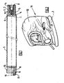
- Such a fluid storage device can be used in a safety hood 11 as shown in FIG. figure 2 .
- the hood 11 comprises an envelope 12 intended to be disposed on the head of a user; the second calibrated outlet orifice 8 opening into the envelope 12.
- the storage device 1 is disposed at the base of the envelope and has a circular shape to allow its arrangement around the neck of a user.
- the storage device is not limited to the above application.
- the storage device can be used as a supply of mechanical energy carrier gas for an actuating member of a mechanical part, for example for actuating a door, a vehicle hood, for the filling an air bag or the like.
Claims (20)
- Vorrichtung zur Speicherung von unter Druck stehendem Fluid, insbesondere von unter Druck stehendem Gas, mit einem Körper (1), der ein Speichervolumen definiert, einer ersten Öffnung (2), insbesondere zum Füllen des Körpers (1), und Mitteln zum Verschließen der ersten Öffnung (2), die einen Sitz (4) und einen Verschluss (5), der relativ zum Sitz (4) zwischen einer Öffnungsposition und einer Schließposition der ersten Öffnung (2) verschoben werden kann, aufweisen, dadurch gekennzeichnet, dass die jeweiligen Teile des Sitzes (4) und des Verschlusses (5), die zusammenwirken sollen, Gegen-Formen und verschiedene bestimmte Härten aufweisen, um in der Schließposition des Verschlusses (5) einen dichten Verschluss für den einmaligen Gebrauch der ersten Öffnung (2) durch plastische Verformung mindestens eines der Teile zu gestatten.
- Vorrichtung nach Anspruch 1, dadurch gekennzeichnet, dass die jeweiligen Teile des Sitzes (4) und des Verschlusses (5) einen Härtenunterschied von ca. 125 HV aufweisen.
- Vorrichtung nach Anspruch 1 oder 2, dadurch gekennzeichnet, dass der Verschluss (5) eine Härte zwischen 250 und 300 HV (Vickershärte) aufweist, während der Sitz (4) eine Härte zwischen 130 und 160 HV (Vickershärte) aufweist.
- Vorrichtung nach einem der Ansprüche 1 bis 3, dadurch gekennzeichnet, dass der Sitz (4) aus einem rostfreien Material, wie zum Beispiel Z2CND17-13, besteht, während der Verschluss (5) aus einem der Kupfer-Nickel-Materialien, wie zum Beispiel CuNi14A12, besteht.
- Vorrichtung nach einem der Ansprüche 1 bis 4, dadurch gekennzeichnet, dass die jeweiligen Teile des Sitzes (4) und des Verschlusses (5) aus Stahl-Metallen bzw. -Metalllegierungen bestehen.
- Vorrichtung nach einem der Ansprüche 1 bis 5, dadurch gekennzeichnet, dass die Gegen-Formen eine scharfe Kante, die an dem Sitz (4) oder an dem Verschluss (5) ausgebildet ist, und eine im Wesentlichen gleichmäßige Aufnahmefläche, die an dem Verschluss (5) bzw. an dem Sitz (4) ausgebildet ist, aufweisen.
- Vorrichtung nach einem der Ansprüche 1 bis 6, dadurch gekennzeichnet, dass der Sitz (4) durch eine kreisförmige Kante begrenzt wird, die die erste Öffnung (2) begrenzt, und dass der Verschluss (5) eine allgemein kegelstumpfförmige Gestalt aufweist, die das Schließen der ersten Öffnung (2) durch Klemmen des Kegelstumpfes gegen die Kante unter teilweisem Eindringen in den Kegelstumpf durch die erste Öffnung (2) gestatten kann.
- Vorrichtung nach einem der vorhergehenden Ansprüche, dadurch gekennzeichnet, dass sie Mittel (6) aufweist, die ein Sicherheitsventil bilden, das das Abführen des Fluids aus dem Körper (1) heraus, wenn die Vorrichtung einer bestimmten Grenztemperatur ausgesetzt ist, gestattet.
- Vorrichtung nach Anspruch 8, dadurch gekennzeichnet, dass die ein Sicherheitsventil bildenden Mittel (6) einen Entlastungskanal aufweisen, der durch den Verschluss (5) ausgebildet ist und das Speichervolumen mit dem Äußeren des Körpers (1) verbinden kann, wobei der Entlastungskanal durch ein bei der bestimmten Grenztemperatur schmelzbares Glied (6), wie zum Beispiel eine Metalllegierungsablagerung, verschlossen ist.
- Vorrichtung nach Anspruch 9, dadurch gekennzeichnet, dass der Entlastungskanal das Speichervolumen über einen von dem Einlass des Füllkanals verschiedenen Durchtritt mit dem Äußeren des Körpers verbinden kann.
- Vorrichtung nach den Ansprüchen 1 bis 10, dadurch gekennzeichnet, dass die Vorrichtung Dichtungsmittel, wie zum Beispiel einen O-Ring, der zwischen dem Verschluss und dem Körper angeordnet ist, aufweist.
- Vorrichtung nach einem der vorhergehenden Ansprüche, dadurch gekennzeichnet, dass sie eine Füllleitung aufweist, die einerseits an der ersten Öffnung (2) und andererseits an einem mit dem Äußeren der Vorrichtung verbundenen Einlass (3) angeschlossen ist.
- Vorrichtung nach den Ansprüchen 11 und 12, dadurch gekennzeichnet, dass die Dichtungsmittel in dem Entlastungskanal und außerhalb der Füllleitung angeordnet sind.
- Vorrichtung nach Anspruch 12 oder 13, dadurch gekennzeichnet, dass die Füllleitung durch eine Abzweigung des Entlastungskanals gebildet wird, so dass die Füllleitung und der Entlastungskanal einen gemeinsamen Teil aufweisen und jeweils durch die erste Öffnung passieren.
- Vorrichtung nach einem der vorhergehenden Ansprüche, dadurch gekennzeichnet, dass der Verschluss (5) durch Schrauben in die Vorrichtung relativ zum Sitz (4) bewegt werden kann.
- Vorrichtung nach einem der vorhergehenden Ansprüche, dadurch gekennzeichnet, dass sie eine zweite Ausgangs-Öffnung (8) aufweist, um insbesondere die Zufuhr von Fluid aus dem Speichervolumen zu einem äußeren Verbraucher zu gestatten.
- Vorrichtung nach einem der Ansprüche 1 bis 16, dadurch gekennzeichnet, dass die Vorrichtung eine Versiegelung zwischen dem Verschluss und dem Körper bildende Mittel aufweist, wie zum Beispiel einen Klebstoff- oder Harzstrang, um die Integrität der Position des Verschlusses bezüglich des Sitzes zu gewährleisten.
- Maske zur Zuführung eines mit Sauerstoff angereicherten Gasgemisches, dadurch gekennzeichnet, dass sie eine Vorrichtung zur Speicherung von unter Druck stehendem Fluid nach einem der vorhergehenden Ansprüche aufweist.
- Maske nach Anspruch 18, die eine Umhüllung (12) aufweist, die auf dem Kopf eines Benutzers angeordnet werden soll; dadurch gekennzeichnet, dass die Vorrichtung zur Speicherung von unter Druck stehendem Fluid eine zweite, kalibrierte Ausgangs-Öffnung (8) aufweist, die in der Umhüllung (12) mündet, wobei die zweite Öffnung (8) durch einen entfernbaren oder eine Sollbruchstelle aufweisenden Stopfen (10) verschlossen ist.
- Glied zur Betätigung eines mechanischen Teils, insbesondere einer Tür oder eines Airbags, mit einer Vorrichtung zur Speicherung von unter Druck stehendem Fluid, die unter Druck stehendes Gas enthalten soll, einem System zur Abgabe des unter Druck stehenden Gases, zum Beispiel ein pyrotechnisches System, um die Erzeugung einer Betätigungskraft zu gestatten, dadurch gekennzeichnet, dass die Vorrichtung zur Speicherung von unter Druck stehendem Gas einem der Ansprüche 1 bis 17 entspricht.
Applications Claiming Priority (1)
| Application Number | Priority Date | Filing Date | Title |
|---|---|---|---|
| FR0553633A FR2893994B1 (fr) | 2005-11-30 | 2005-11-30 | Dispositif de stockage de fluide sous pression, masque et organe d'actionnement comprenant un tel dispositif |
Publications (3)
| Publication Number | Publication Date |
|---|---|
| EP1793147A2 EP1793147A2 (de) | 2007-06-06 |
| EP1793147A3 EP1793147A3 (de) | 2008-03-05 |
| EP1793147B1 true EP1793147B1 (de) | 2009-08-19 |
Family
ID=36869888
Family Applications (1)
| Application Number | Title | Priority Date | Filing Date |
|---|---|---|---|
| EP06301083A Active EP1793147B1 (de) | 2005-11-30 | 2006-10-24 | Unter Druck stehender Flüssigkeitsspeicher, Maske und Betätigungsvorrichtung mit einem solchen Flüssigkeitsspeicher |
Country Status (4)
| Country | Link |
|---|---|
| EP (1) | EP1793147B1 (de) |
| AT (1) | ATE440236T1 (de) |
| DE (1) | DE602006008558D1 (de) |
| FR (1) | FR2893994B1 (de) |
Families Citing this family (4)
| Publication number | Priority date | Publication date | Assignee | Title |
|---|---|---|---|---|
| FR2951243B1 (fr) * | 2009-10-12 | 2015-04-03 | Air Liquide | Dispositif de securite pour recipient de gaz et recipient pourvu d'un tel dispositif |
| FR3024370B1 (fr) * | 2014-08-01 | 2016-07-22 | Air Liquide | Cagoule de protection respiratoire |
| FR3024371B1 (fr) * | 2014-08-01 | 2018-01-26 | L'air Liquide, Societe Anonyme Pour L'etude Et L'exploitation Des Procedes Georges Claude | Cagoule de protection respiratoire |
| CN113471752A (zh) * | 2021-05-17 | 2021-10-01 | 宜宾天亿新材料科技有限公司 | 对插式防水接头及其生产方法 |
Family Cites Families (6)
| Publication number | Priority date | Publication date | Assignee | Title |
|---|---|---|---|---|
| GB2317216A (en) * | 1996-09-12 | 1998-03-18 | Bsa Guns | Sealing valve for gas bottle |
| US6007049A (en) * | 1996-09-19 | 1999-12-28 | Wass; Lloyd G. | High pressure gas valve having an inverted stem/seat design and a soft seated removable stem cartridge |
| JP2000130607A (ja) * | 1998-10-27 | 2000-05-12 | Mitsubishi Electric Corp | 圧力制御弁の窒化処理方法 |
| EP1128109A1 (de) * | 2000-02-22 | 2001-08-29 | Siemens Building Technologies AG | Ventil für eine Stelleinrichtung |
| GB2368532B (en) * | 2000-11-02 | 2004-09-08 | Nick Foss | Breathing apparatus |
| JP2002211346A (ja) * | 2001-01-15 | 2002-07-31 | Takata Corp | インフレータ |
-
2005
- 2005-11-30 FR FR0553633A patent/FR2893994B1/fr not_active Expired - Fee Related
-
2006
- 2006-10-24 AT AT06301083T patent/ATE440236T1/de not_active IP Right Cessation
- 2006-10-24 EP EP06301083A patent/EP1793147B1/de active Active
- 2006-10-24 DE DE602006008558T patent/DE602006008558D1/de active Active
Also Published As
| Publication number | Publication date |
|---|---|
| EP1793147A3 (de) | 2008-03-05 |
| FR2893994A1 (fr) | 2007-06-01 |
| EP1793147A2 (de) | 2007-06-06 |
| FR2893994B1 (fr) | 2007-12-28 |
| DE602006008558D1 (de) | 2009-10-01 |
| ATE440236T1 (de) | 2009-09-15 |
Similar Documents
| Publication | Publication Date | Title |
|---|---|---|
| EP1943456B1 (de) | Element zur steuerung der füllung mit und/oder entnahme von einem druckgas, tank und schaltung mit einem solchen element | |
| US8550105B2 (en) | Valve system of high pressure tank for vehicle | |
| EP2250426B1 (de) | Gasabfüll- und ausgabevorrichtung sowie abfüllverfahren | |
| ES2276101T3 (es) | Combinacion de valvula de descarga termica y de presion. | |
| EP2247889A1 (de) | Gasabfüll- und ausgabevorrichtung, gefäss mit einer solchen vorrichtung und operationsschaltung dafür | |
| FR2962519A1 (fr) | Raccord de remplissage, recipient et procede de remplissage correspondants | |
| EP1793147B1 (de) | Unter Druck stehender Flüssigkeitsspeicher, Maske und Betätigungsvorrichtung mit einem solchen Flüssigkeitsspeicher | |
| EP0010465B1 (de) | Sich automatisch öffnendes Ventil, insbesondere für Feuerlöschanlagen | |
| FR2981720A1 (fr) | Robinet d'isolement | |
| FR2951799A1 (fr) | Soupape de reservoir de gaz | |
| JP2005282638A (ja) | 安全弁 | |
| WO2011000839A1 (fr) | Detendeur avec obturateur et selecteur de debit | |
| FR2964439A1 (fr) | Dispositif de purge automatique d'un reservoir et reservoir comprenant un tel dispositif | |
| FR3016007A1 (fr) | Dispositif d'actionnement d'urgence notamment destine a un ouvrant d'aeronef | |
| EP2486312B1 (de) | Sicherheitsvorrichtung und behälter mit dieser vorrichtung | |
| EP1069355A2 (de) | Sicherheitsventil für Druckbehälter | |
| FR2878307A1 (fr) | Dispositif d'obturation equipe d'un clapet de pression | |
| EP2435750B1 (de) | Sicherheitsvorrichtung für unter druck stehendes gas | |
| FR2844572A1 (fr) | Dispositif de securite a disque de rupture servant a pallier les surpressions de fluide | |
| FR2872249A1 (fr) | Electrovanne a execution par deviation de fluide | |
| WO2023148048A1 (fr) | Vanne pour fluide sous pression, et réservoir ou ensemble de réservoirs de fluide sous pression | |
| EP4034803B1 (de) | Verpackungsvorrichtung, anordnung mit einer solchen vorrichtung und einem behälter, deren verwendung und verfahren zum füllen oder entnehmen | |
| EP1734293B1 (de) | Hahn für Kanalisation der Acetylenzuleitung | |
| FR2740510A1 (fr) | Dispositif de liberation pour des conduites de propergol | |
| FR3008767A1 (fr) | Dispositif de securite et recipient de stockage de gaz pourvu d'un tel dispositif |
Legal Events
| Date | Code | Title | Description |
|---|---|---|---|
| PUAI | Public reference made under article 153(3) epc to a published international application that has entered the european phase |
Free format text: ORIGINAL CODE: 0009012 |
|
| AK | Designated contracting states |
Kind code of ref document: A2 Designated state(s): AT BE BG CH CY CZ DE DK EE ES FI FR GB GR HU IE IS IT LI LT LU LV MC NL PL PT RO SE SI SK TR |
|
| AX | Request for extension of the european patent |
Extension state: AL BA HR MK YU |
|
| PUAL | Search report despatched |
Free format text: ORIGINAL CODE: 0009013 |
|
| AK | Designated contracting states |
Kind code of ref document: A3 Designated state(s): AT BE BG CH CY CZ DE DK EE ES FI FR GB GR HU IE IS IT LI LT LU LV MC NL PL PT RO SE SI SK TR |
|
| AX | Request for extension of the european patent |
Extension state: AL BA HR MK YU |
|
| 17P | Request for examination filed |
Effective date: 20080328 |
|
| AKX | Designation fees paid |
Designated state(s): AT BE BG CH CY CZ DE DK EE ES FI FR GB GR HU IE IS IT LI LT LU LV MC NL PL PT RO SE SI SK TR |
|
| AXX | Extension fees paid |
Extension state: RS Payment date: 20080328 Extension state: AL Payment date: 20080328 Extension state: HR Payment date: 20080328 Extension state: BA Payment date: 20080328 Extension state: MK Payment date: 20080328 |
|
| GRAP | Despatch of communication of intention to grant a patent |
Free format text: ORIGINAL CODE: EPIDOSNIGR1 |
|
| GRAS | Grant fee paid |
Free format text: ORIGINAL CODE: EPIDOSNIGR3 |
|
| GRAA | (expected) grant |
Free format text: ORIGINAL CODE: 0009210 |
|
| AK | Designated contracting states |
Kind code of ref document: B1 Designated state(s): AT BE BG CH CY CZ DE DK EE ES FI FR GB GR HU IE IS IT LI LT LU LV MC NL PL PT RO SE SI SK TR |
|
| AX | Request for extension of the european patent |
Extension state: AL BA HR MK RS |
|
| REG | Reference to a national code |
Ref country code: GB Ref legal event code: FG4D Free format text: NOT ENGLISH |
|
| REG | Reference to a national code |
Ref country code: CH Ref legal event code: EP |
|
| REG | Reference to a national code |
Ref country code: IE Ref legal event code: FG4D |
|
| REF | Corresponds to: |
Ref document number: 602006008558 Country of ref document: DE Date of ref document: 20091001 Kind code of ref document: P |
|
| REG | Reference to a national code |
Ref country code: SE Ref legal event code: TRGR |
|
| LTIE | Lt: invalidation of european patent or patent extension |
Effective date: 20090819 |
|
| PG25 | Lapsed in a contracting state [announced via postgrant information from national office to epo] |
Ref country code: LT Free format text: LAPSE BECAUSE OF FAILURE TO SUBMIT A TRANSLATION OF THE DESCRIPTION OR TO PAY THE FEE WITHIN THE PRESCRIBED TIME-LIMIT Effective date: 20090819 Ref country code: AT Free format text: LAPSE BECAUSE OF FAILURE TO SUBMIT A TRANSLATION OF THE DESCRIPTION OR TO PAY THE FEE WITHIN THE PRESCRIBED TIME-LIMIT Effective date: 20090819 Ref country code: ES Free format text: LAPSE BECAUSE OF FAILURE TO SUBMIT A TRANSLATION OF THE DESCRIPTION OR TO PAY THE FEE WITHIN THE PRESCRIBED TIME-LIMIT Effective date: 20091130 Ref country code: IS Free format text: LAPSE BECAUSE OF FAILURE TO SUBMIT A TRANSLATION OF THE DESCRIPTION OR TO PAY THE FEE WITHIN THE PRESCRIBED TIME-LIMIT Effective date: 20091219 Ref country code: FI Free format text: LAPSE BECAUSE OF FAILURE TO SUBMIT A TRANSLATION OF THE DESCRIPTION OR TO PAY THE FEE WITHIN THE PRESCRIBED TIME-LIMIT Effective date: 20090819 |
|
| NLV1 | Nl: lapsed or annulled due to failure to fulfill the requirements of art. 29p and 29m of the patents act | ||
| PG25 | Lapsed in a contracting state [announced via postgrant information from national office to epo] |
Ref country code: NL Free format text: LAPSE BECAUSE OF FAILURE TO SUBMIT A TRANSLATION OF THE DESCRIPTION OR TO PAY THE FEE WITHIN THE PRESCRIBED TIME-LIMIT Effective date: 20090819 Ref country code: LV Free format text: LAPSE BECAUSE OF FAILURE TO SUBMIT A TRANSLATION OF THE DESCRIPTION OR TO PAY THE FEE WITHIN THE PRESCRIBED TIME-LIMIT Effective date: 20090819 Ref country code: PL Free format text: LAPSE BECAUSE OF FAILURE TO SUBMIT A TRANSLATION OF THE DESCRIPTION OR TO PAY THE FEE WITHIN THE PRESCRIBED TIME-LIMIT Effective date: 20090819 Ref country code: SI Free format text: LAPSE BECAUSE OF FAILURE TO SUBMIT A TRANSLATION OF THE DESCRIPTION OR TO PAY THE FEE WITHIN THE PRESCRIBED TIME-LIMIT Effective date: 20090819 |
|
| REG | Reference to a national code |
Ref country code: IE Ref legal event code: FD4D |
|
| PG25 | Lapsed in a contracting state [announced via postgrant information from national office to epo] |
Ref country code: PT Free format text: LAPSE BECAUSE OF FAILURE TO SUBMIT A TRANSLATION OF THE DESCRIPTION OR TO PAY THE FEE WITHIN THE PRESCRIBED TIME-LIMIT Effective date: 20091221 Ref country code: BG Free format text: LAPSE BECAUSE OF FAILURE TO SUBMIT A TRANSLATION OF THE DESCRIPTION OR TO PAY THE FEE WITHIN THE PRESCRIBED TIME-LIMIT Effective date: 20091119 Ref country code: CY Free format text: LAPSE BECAUSE OF FAILURE TO SUBMIT A TRANSLATION OF THE DESCRIPTION OR TO PAY THE FEE WITHIN THE PRESCRIBED TIME-LIMIT Effective date: 20090819 |
|
| BERE | Be: lapsed |
Owner name: L'AIR LIQUIDE, S.A. POUR L'ETUDE ET L'EXPLOITATIO Effective date: 20091031 |
|
| PG25 | Lapsed in a contracting state [announced via postgrant information from national office to epo] |
Ref country code: RO Free format text: LAPSE BECAUSE OF FAILURE TO SUBMIT A TRANSLATION OF THE DESCRIPTION OR TO PAY THE FEE WITHIN THE PRESCRIBED TIME-LIMIT Effective date: 20090819 Ref country code: IE Free format text: LAPSE BECAUSE OF FAILURE TO SUBMIT A TRANSLATION OF THE DESCRIPTION OR TO PAY THE FEE WITHIN THE PRESCRIBED TIME-LIMIT Effective date: 20090819 Ref country code: DK Free format text: LAPSE BECAUSE OF FAILURE TO SUBMIT A TRANSLATION OF THE DESCRIPTION OR TO PAY THE FEE WITHIN THE PRESCRIBED TIME-LIMIT Effective date: 20090819 Ref country code: EE Free format text: LAPSE BECAUSE OF FAILURE TO SUBMIT A TRANSLATION OF THE DESCRIPTION OR TO PAY THE FEE WITHIN THE PRESCRIBED TIME-LIMIT Effective date: 20090819 Ref country code: CZ Free format text: LAPSE BECAUSE OF FAILURE TO SUBMIT A TRANSLATION OF THE DESCRIPTION OR TO PAY THE FEE WITHIN THE PRESCRIBED TIME-LIMIT Effective date: 20090819 |
|
| PG25 | Lapsed in a contracting state [announced via postgrant information from national office to epo] |
Ref country code: SK Free format text: LAPSE BECAUSE OF FAILURE TO SUBMIT A TRANSLATION OF THE DESCRIPTION OR TO PAY THE FEE WITHIN THE PRESCRIBED TIME-LIMIT Effective date: 20090819 Ref country code: MC Free format text: LAPSE BECAUSE OF NON-PAYMENT OF DUE FEES Effective date: 20091031 |
|
| PLBE | No opposition filed within time limit |
Free format text: ORIGINAL CODE: 0009261 |
|
| STAA | Information on the status of an ep patent application or granted ep patent |
Free format text: STATUS: NO OPPOSITION FILED WITHIN TIME LIMIT |
|
| 26N | No opposition filed |
Effective date: 20100520 |
|
| PG25 | Lapsed in a contracting state [announced via postgrant information from national office to epo] |
Ref country code: GR Free format text: LAPSE BECAUSE OF FAILURE TO SUBMIT A TRANSLATION OF THE DESCRIPTION OR TO PAY THE FEE WITHIN THE PRESCRIBED TIME-LIMIT Effective date: 20091120 Ref country code: BE Free format text: LAPSE BECAUSE OF NON-PAYMENT OF DUE FEES Effective date: 20091031 |
|
| PG25 | Lapsed in a contracting state [announced via postgrant information from national office to epo] |
Ref country code: LU Free format text: LAPSE BECAUSE OF NON-PAYMENT OF DUE FEES Effective date: 20091024 |
|
| REG | Reference to a national code |
Ref country code: CH Ref legal event code: PL |
|
| PG25 | Lapsed in a contracting state [announced via postgrant information from national office to epo] |
Ref country code: HU Free format text: LAPSE BECAUSE OF FAILURE TO SUBMIT A TRANSLATION OF THE DESCRIPTION OR TO PAY THE FEE WITHIN THE PRESCRIBED TIME-LIMIT Effective date: 20100220 |
|
| PG25 | Lapsed in a contracting state [announced via postgrant information from national office to epo] |
Ref country code: LI Free format text: LAPSE BECAUSE OF NON-PAYMENT OF DUE FEES Effective date: 20101031 Ref country code: CH Free format text: LAPSE BECAUSE OF NON-PAYMENT OF DUE FEES Effective date: 20101031 |
|
| PG25 | Lapsed in a contracting state [announced via postgrant information from national office to epo] |
Ref country code: TR Free format text: LAPSE BECAUSE OF FAILURE TO SUBMIT A TRANSLATION OF THE DESCRIPTION OR TO PAY THE FEE WITHIN THE PRESCRIBED TIME-LIMIT Effective date: 20090819 |
|
| REG | Reference to a national code |
Ref country code: FR Ref legal event code: PLFP Year of fee payment: 10 |
|
| REG | Reference to a national code |
Ref country code: FR Ref legal event code: PLFP Year of fee payment: 11 |
|
| REG | Reference to a national code |
Ref country code: FR Ref legal event code: PLFP Year of fee payment: 12 |
|
| REG | Reference to a national code |
Ref country code: FR Ref legal event code: PLFP Year of fee payment: 13 |
|
| PGFP | Annual fee paid to national office [announced via postgrant information from national office to epo] |
Ref country code: SE Payment date: 20211020 Year of fee payment: 16 |
|
| PGFP | Annual fee paid to national office [announced via postgrant information from national office to epo] |
Ref country code: IT Payment date: 20211021 Year of fee payment: 16 |
|
| REG | Reference to a national code |
Ref country code: SE Ref legal event code: EUG |
|
| PG25 | Lapsed in a contracting state [announced via postgrant information from national office to epo] |
Ref country code: SE Free format text: LAPSE BECAUSE OF NON-PAYMENT OF DUE FEES Effective date: 20221025 |
|
| PG25 | Lapsed in a contracting state [announced via postgrant information from national office to epo] |
Ref country code: IT Free format text: LAPSE BECAUSE OF NON-PAYMENT OF DUE FEES Effective date: 20221024 |
|
| PGFP | Annual fee paid to national office [announced via postgrant information from national office to epo] |
Ref country code: GB Payment date: 20231020 Year of fee payment: 18 |
|
| PGFP | Annual fee paid to national office [announced via postgrant information from national office to epo] |
Ref country code: FR Payment date: 20231023 Year of fee payment: 18 Ref country code: DE Payment date: 20231020 Year of fee payment: 18 |