EP1791698B1 - Fluid drop ejection system capable of removing dissolved gas from fluid - Google Patents
Fluid drop ejection system capable of removing dissolved gas from fluid Download PDFInfo
- Publication number
- EP1791698B1 EP1791698B1 EP05808350A EP05808350A EP1791698B1 EP 1791698 B1 EP1791698 B1 EP 1791698B1 EP 05808350 A EP05808350 A EP 05808350A EP 05808350 A EP05808350 A EP 05808350A EP 1791698 B1 EP1791698 B1 EP 1791698B1
- Authority
- EP
- European Patent Office
- Prior art keywords
- fluid
- reservoir
- drop ejection
- ink
- partial vacuum
- Prior art date
- Legal status (The legal status is an assumption and is not a legal conclusion. Google has not performed a legal analysis and makes no representation as to the accuracy of the status listed.)
- Active
Links
- 239000012530 fluid Substances 0.000 title claims abstract description 114
- 230000005499 meniscus Effects 0.000 claims description 28
- 238000000034 method Methods 0.000 claims description 14
- 230000004044 response Effects 0.000 claims description 8
- 238000003756 stirring Methods 0.000 claims description 8
- 238000000605 extraction Methods 0.000 claims description 5
- 238000004891 communication Methods 0.000 claims description 4
- 230000001419 dependent effect Effects 0.000 claims description 4
- 238000005086 pumping Methods 0.000 claims description 4
- 239000000976 ink Substances 0.000 description 171
- 238000007872 degassing Methods 0.000 description 18
- 239000007789 gas Substances 0.000 description 18
- 238000007641 inkjet printing Methods 0.000 description 11
- 239000000463 material Substances 0.000 description 8
- XLYOFNOQVPJJNP-UHFFFAOYSA-N water Substances O XLYOFNOQVPJJNP-UHFFFAOYSA-N 0.000 description 8
- 239000012528 membrane Substances 0.000 description 7
- 238000007639 printing Methods 0.000 description 6
- 239000002904 solvent Substances 0.000 description 6
- 230000007246 mechanism Effects 0.000 description 4
- 230000008901 benefit Effects 0.000 description 3
- 239000003086 colorant Substances 0.000 description 3
- 239000012943 hotmelt Substances 0.000 description 3
- 229920000642 polymer Polymers 0.000 description 3
- XUIMIQQOPSSXEZ-UHFFFAOYSA-N Silicon Chemical compound [Si] XUIMIQQOPSSXEZ-UHFFFAOYSA-N 0.000 description 2
- 238000006243 chemical reaction Methods 0.000 description 2
- 230000006837 decompression Effects 0.000 description 2
- 239000001041 dye based ink Substances 0.000 description 2
- 238000009472 formulation Methods 0.000 description 2
- 230000002452 interceptive effect Effects 0.000 description 2
- 238000004519 manufacturing process Methods 0.000 description 2
- 239000002184 metal Substances 0.000 description 2
- 239000000203 mixture Substances 0.000 description 2
- 239000003973 paint Substances 0.000 description 2
- 239000001042 pigment based ink Substances 0.000 description 2
- 229910052710 silicon Inorganic materials 0.000 description 2
- 239000010703 silicon Substances 0.000 description 2
- 239000000725 suspension Substances 0.000 description 2
- 230000032258 transport Effects 0.000 description 2
- 238000011144 upstream manufacturing Methods 0.000 description 2
- 239000002253 acid Substances 0.000 description 1
- 150000007513 acids Chemical class 0.000 description 1
- 150000001298 alcohols Chemical class 0.000 description 1
- 238000003491 array Methods 0.000 description 1
- 238000005452 bending Methods 0.000 description 1
- 239000006227 byproduct Substances 0.000 description 1
- 230000001143 conditioned effect Effects 0.000 description 1
- 239000013078 crystal Substances 0.000 description 1
- 230000003247 decreasing effect Effects 0.000 description 1
- 238000009792 diffusion process Methods 0.000 description 1
- 238000004090 dissolution Methods 0.000 description 1
- 239000004615 ingredient Substances 0.000 description 1
- 239000007788 liquid Substances 0.000 description 1
- 230000007257 malfunction Effects 0.000 description 1
- 230000005012 migration Effects 0.000 description 1
- 238000013508 migration Methods 0.000 description 1
- 239000002245 particle Substances 0.000 description 1
- 239000000049 pigment Substances 0.000 description 1
- 230000037452 priming Effects 0.000 description 1
- 239000004065 semiconductor Substances 0.000 description 1
Images

Classifications
-
- B—PERFORMING OPERATIONS; TRANSPORTING
- B41—PRINTING; LINING MACHINES; TYPEWRITERS; STAMPS
- B41J—TYPEWRITERS; SELECTIVE PRINTING MECHANISMS, i.e. MECHANISMS PRINTING OTHERWISE THAN FROM A FORME; CORRECTION OF TYPOGRAPHICAL ERRORS
- B41J2/00—Typewriters or selective printing mechanisms characterised by the printing or marking process for which they are designed
- B41J2/005—Typewriters or selective printing mechanisms characterised by the printing or marking process for which they are designed characterised by bringing liquid or particles selectively into contact with a printing material
- B41J2/01—Ink jet
- B41J2/17—Ink jet characterised by ink handling
- B41J2/19—Ink jet characterised by ink handling for removing air bubbles
-
- B—PERFORMING OPERATIONS; TRANSPORTING
- B41—PRINTING; LINING MACHINES; TYPEWRITERS; STAMPS
- B41J—TYPEWRITERS; SELECTIVE PRINTING MECHANISMS, i.e. MECHANISMS PRINTING OTHERWISE THAN FROM A FORME; CORRECTION OF TYPOGRAPHICAL ERRORS
- B41J2/00—Typewriters or selective printing mechanisms characterised by the printing or marking process for which they are designed
- B41J2/005—Typewriters or selective printing mechanisms characterised by the printing or marking process for which they are designed characterised by bringing liquid or particles selectively into contact with a printing material
- B41J2/01—Ink jet
- B41J2/17—Ink jet characterised by ink handling
Definitions
- This application relates to the field of fluid drop ejection.
- ink is supplied to a chamber or passage connected to a nozzle from which the ink is ejected drop-by-drop as a result of successive cycles of decreased and increased pressure applied to the ink in the passage.
- the pressure cycles can be generated by a piezoelectric crystal, a heater, or a Micro Mechanical Device. If the ink introduced into the passage contains dissolved air, decompression of the ink during the reduced pressure portions of the pressure cycle may cause the dissolved air to form small bubbles in the ink within the passage. Repeated decompression of the ink in the chamber causes these bubbles to grow and such bubbles can produce malfunctions of the ink jet apparatus.
- Degassing of ink typically utilizes a semi-permeable membrane that is in contact with the ink on one face of the membrane. Reduced pressure is applied to the other side of the membrane to extract dissolved air from the ink in the ink path.
- an evacuated structure that removes air accumulated in a container that contains material held at a first pressure.
- the evacuated structure has a shell that includes a slowly defusing air-permeable material interfacing to a volume of space evacuated to a second pressure less than the first pressure in the container. Unwanted air that accumulates in the container is drawn into the volume of space of the evacuated structure due to the difference in pressure between the interiour of the container and the interior of the shell.
- the invention is directed to a drop ejection system as defined in independent claim 1.
- the invention is directed to a method of removing dissolved gas in a fluid ejection system as defined in independent claim 14.
- the partial vacuum may enable the extraction of dissolved air or dissolved vapor from the fluid.
- a fluid valve may shut off the fluid path from the second reservoir to the first reservoir.
- a stirring device may stir the fluid to assist the extraction of dissolved air from the fluid.
- a pump may pump the fluid from the second reservoir to the first reservoir through the second fluid path.
- the drop ejection head may have a fluid conduit to supply the ink received from the first reservoir to the nozzles.
- a fluid-feeding path to a reservoir may be closed when the partial vacuum is generated in the upper portion of the reservoir.
- the drop ejection head may be movable without requiring movement of the second reservoir.
- a control unit may controls the air pump to produce the partial vacuum.
- the air pump may be controlled in response to one or more properties of the fluid, to the idle time of the drop ejection head, or to the fluid filling status or the fluid level.
- the fluid may includes one of more of an ink, a dye-based ink, a pigment-based ink, a hot-melt ink, a colorant containing fluid, a paint, a polymer solution, a solvent, a colloidal suspension, and a metal containing fluid.
- the drop ejection head may have one or more fluid ejection actuators, e.g., a piezoelectric transducer or a heater, that can actuate the fluid ejection through the nozzles.
- a surface of fluid in one of reservoirs may control the meniscus pressure at the nozzles in the drop ejection head.
- Embodiments may include one or more of the following advantages.
- the gas dissolved in the fluid of a fluid ejection system is removed using a so called bulk degassing arrangement without using the typical deaerator membranes.
- the gas in the fluid is removed from the fluid/air interface by a partial vacuum above the fluid body in a sealable fluid container upstream to the fluid ejection head.
- the fluid container can be a reservoir that is connected with the fluid ejection head through a fluid path.
- the degassing mechanism When the degassing mechanism is arranged in the fluid reservoir, the degassing operations can be conducted without interfering with the fluid ejection operations.
- the fluid ejection and the degassing operations can both be effective because they can be separately optimized.
- the disclosed system is simple, less expensive, and easier to maintain.
- the system is also effective to ink formulations that contain trace amount of high vapor pressure materials such as water and solvents.
- FIG. 1 illustrates an ink in an ink jet printing system 5 having an arrangement for bulk degassing.
- the ink jet printing system 5 includes an ink jet print head module 10 having a plurality of ink nozzles 20 typically arranged in arrays on a nozzle plate 21, a fluid conduit 30 in the ink jet print head module 10 for supplying ink to the ink nozzles 20, a meniscus control reservoir 40 for storing ink that controls the meniscus pressure in the ink nozzles 20, and an ink passage 50 for supplying ink from the meniscus control reservoir 40 to the fluid conduit 30.
- ink completely fills the fluid conduit 40, e.g., substantially all of the of the walls of the fluid conduit 30 are in contact with the ink fluid.
- the ink fluid contained in the fluid conduit 30 has substantially no free surface.
- ink does not completely fill the meniscus control reservoir 40.
- the meniscus control reservoir 40 holds an ink body 64 in its lower portion and a space 65 above.
- the meniscus control reservoir 40 includes the ink-feeding path 60 having an ink filter 61 that supplies ink to the meniscus control reservoir 40.
- the ink in the meniscus control reservoir 40 is supplied to the fluid conduit 30 by an ink pump 68 along the ink passage 50.
- a meniscus control air pump 70 can create a partial vacuum in the space 65 above the ink surface. The height of the ink surface and the partial vacuum in the meniscus control reservoir 40 controls the meniscus of the ink nozzles 20.
- the ink jet printing system 5 further includes an ink tank 72 upstream of the meniscus control reservoir 40.
- the lower portion of the ink tank 72 holds a body of ink 73 that can be pumped by ink pump 74 to the meniscus control reservoir 40 through ink path 60.
- the ink tank 72 is also not completely full, so that a free surface is formed over the ink body 73.
- the ink flow from the ink tank 72 to the meniscus control reservoir 40 along the ink path 60 can be shut off by closing a check valve 77.
- a partial vacuum can then be created in a space 78 above the ink surface by pulling air by a degassing vacuum pump 75.
- Dissolved gas is removed or extracted from the ink body 73 at the ink surface, which reduces the concentration of the dissolved gas in the ink body 73.
- the rate of gas removal from the ink body 73 is proportional to the area of its free surface. For example, a large free surface can be formed across the horizontal cross-section of the ink tank 72.
- a stirrer 76 can stir the ink body 73 during the gas removal to assist the migration of dissolved gas to the ink surface.
- the operations of the valve 77, the ink pump 74, the degassing vacuum pump 75 and the stirrer 76 are under the control of a control unit 90.
- the valve 77 can be a check valve, a variable valve, a solenoid valve, a servo valve, etc.
- the valve 77 can be manually operated in degassing operations.
- the gas-removal arrangement described above and shown in Figure 1 can be referred to as a bulk-degassing system.
- the result of the degassing operations is that the ink is conditioned so that the relative concentration of any gases or volatile liquids is well below the saturation concentration for those materials at the operating conditions of the ink jet print head module 10. This ensures the best possible priming performance of the ink nozzles 20, and the best possible resistance to rectified diffusion.
- the ink jet printing system 5 is an industrial printing system.
- the ink tank 72 is a bulk paint-pot with a 4 liter capacity having one or more internal stirrers.
- the ink tank 72 is periodically refilled with jugs from the ink manufacturer.
- the ink tank 72 is sealed and a good vacuum (e.g. at 0.001 Bar (100Pa) is applied to the entire ink tank 72.
- the continuous stirring in the presence of the vacuum is sufficient to eliminate any dissolved air or vapor, and to reduce the concentration of all volatile ingredients to below the saturation level.
- the ink tank 72 can further include a ink feeding path for receiving ink fluid.
- the ink-feeding path includes a check valve that can be closed to create partial vacuum over the ink body in the ink tank 72 during degassing operations.
- the disclosed bulk degassing system not only can remove bubbles of air, it is also especially effective in removing dissolved air and other dissolved high-vapor-pressure materials material (e.g. water, solvents) from the ink body. This is advantageous in comparison to the membrane-based fluid deaerator because the molecules of the high vapor-pressure materials move more readily across the fluid air interface than they do through a membrane. Furthermore, the bulk degassing system and methods disclosed can be applied in combination with a fluid deaerator such as the ones disclosed in commonly assigned US Patents 4,788,556 , 4,940,995 , 4,961,082 , 4,995,940 , and 5,701,148 . .
- Ink types compatible with the bulk degassing system include water-based inks, solvent-based inks, dye-based inks, pigment-based inks, and hot melt inks.
- the ink fluids may include colorants such as a dye or a pigment.
- Other fluids compatible with the system may include polymer solutions, gel solutions, solutions containing particles or low molecular-weight molecules. Unless specific care is taken during manufacturing, inks commonly contain dissolved air at close to saturation concentration. Many inks are likely to contain water and other volatile components such as alcohols and solvents, which may be produced by unintended results of production processes such as stirring in a humid atmosphere or reactions within the ink.
- hot-melt inks are known to evolve water over time as a reaction byproduct of certain acids in the formulation.
- the disclosed system is also compatible with other fluids such as colorant containing fluids, paints, polymer solutions, solvents, colloidal suspensions, and metal containing fluids.
- the partial vacuum created in the ink tank 72 is dependent on one or more properties of the ink.
- the pressure and duration of the partial vacuum can vary under the control of the control unit 90 in accordance to the propensity of the ink to dissolution of air, or the concentration or generation of water and other volatile components in the ink.
- the control unit 90 receives the above and other properties and in response sends signals to the degassing vacuum pump 75 to control the pumping rate and duration, which in turn determines the pressure and the time profile of the partial vacuum.
- gas-removal operations can be dependent on other factors that can impact the level of dissolved air or vapor in the ink body including the idle time of the ink jet printing system 5, the ink filling status and the filling level in the ink tank 72. Gases need to be removed when new ink is added the ink tank 72. Air can also be dissolved into the ink body through ink nozzles 20 etc. if the ink jet printing system stays idle for a period of time.
- the ink jet print head module 10 can include a plurality of ink nozzles 20 that are in fluid communication with the fluid conduit 30.
- Each ink nozzle 20 is associated with one or more ink ejection actuators that can for example include a piezoelectric transducer, a heater, or a MEMS transducer device.
- the ink jet printing system 5 can further comprise an electronic selector that can select the ink nozzle and the associated ink actuators from which the fluid drop will be ejected.
- a portion of the fluid conduit 30 adjacent the associate actuator can be widened to provide a pumping chamber (this chamber is also substantially filled by the ink).
- the ink nozzle 20 in the nozzle plate 21 is connected with an ejection portion of the fluid conduit 30.
- the ink fluid in the ejection portion of the fluid conduit 30 is ejected from the ink nozzle 20 under the control of the control unit 90.
- the ejected ink drop can vary in volume in response to different drive voltage waveforms applied to the ink ejection actuator by the electronic control unit 90.
- the ink jet print head module 10 can exist in the form of piezoelectric ink jet, thermal ink jet, MEMS based ink jet print heads, and other types of ink actuation mechanisms.
- Hoisington et al. U.S. Patent 5,265,315 describes a print head that has a semiconductor print head body and a piezoelectric actuator.
- the print head body is made of silicon, which is etched to define an ink fluid conduit. Nozzle openings are defined by a separate nozzle plate 21, which is attached to the silicon body.
- the piezoelectric actuator has a layer of piezoelectric material, which changes geometry, or bends, in response to an applied voltage. The bending of the piezoelectric layer pressurizes the ink fluid near the ejection portion of the fluid conduit, e.g., in the pumping chamber located along the ink path.
- the ink jet printing system 5 can also include a mechanism 85 that transports an ink receiver 80 along a direction 87.
- the ink jet print head module 10 can move in reciprocating motion driven by a motor via an endless belt. The direction of the motion is often referred to as the fast scan direction.
- the ink jet print head is scanned relative to the ink receiver 80 without requiring moving the meniscus control reservoir 40.
- At least a portion of the ink path 60 is flexible such that the ink jet print head module 10 can be moved without the movement of the ink tank 72.
- the advantage of a separate ink tank 72 from the ink jet print head module 10 is that the gas or vapor dissolved in the ink can be removed without interfering with the movement or printing operations of the ink jet print head module 10.
- a second mechanism can transport the ink receiver 80 along a second direction (commonly referred as the slow scan direction) that is perpendicular to the first direction.
- the slow scan direction a second direction that is perpendicular to the first direction.
- ink drops are ejected from the ink nozzles 20 under the control of an electronic control unit 90 in response to input image data to form an image pattern of ink dots on an ink receiver 80.
- the ink jet print head module 10 disposes ink drops to form a swath of ink dots on the ink receiver 80.
- a page-wide ink jet print head module 10 is formed by a print head bar or an assembly of print head modules.
- the ink jet print head module 10 remains still during printing while the ink receiving media is transported along the slow scan direction under the ink jet print head module 10.
- the ink jet system and methods are compatible with different print head arrangements known in the art. For example, the system and methods are applicable to a single pass ink jet printer with offset inkjet modules disclosed in the commonly assigned US Patent 5,771,052 .
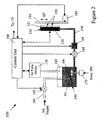
- FIG. 2 illustrates an ink jet printing system 100 that includes an ink jet print head module 110 having a plurality of ink nozzles 120 on a nozzle plate 121, a fluid conduit 130 in the ink jet print head module 100 for supplying ink to the ink nozzles 120, a meniscus control reservoir 140 capable of removing gas from the ink body, an ink passage 150 for supplying ink from the meniscus control reservoir 140 and the fluid conduit 130.
- the fluid conduit 130 is substantially fully wet with the ink fluid.
- the ink fluid contained in the fluid conduit 30 does not contain any substantial free surface.
- the meniscus control reservoir 140 holds an ink body 164 and a space 165 above. A large free surface is formed over the ink body 164.
- the meniscus control reservoir 140 includes an ink-feeding path 160 having an ink filter 161 that supplies ink to the meniscus control reservoir 140.
- the ink-feeding path can be opened or closed by a valve 162.
- An ink pump 168 pumps the ink in the meniscus control reservoir 140 to the fluid conduit 130 along the ink passage 150.
- the ink flow along the ink passage 150 can be shut off a valve 163.
- the operations of the valves 162,163 and the ink pump 168 are under the control of the control unit 190.
- the valve 162 or valve 163 can be a check valve, a variable valve, a solenoid valve, a servo valve, etc.
- the valves 162,163 can be manually operated in degassing operations.
- a partial vacuum can be created in the space 165 by a air pump device 170 that pulls air out of the space 165 under the control of the control unit 190.
- the air pressure in the space 165 over the ink body 164 in the ink reservoir 140 is typically reduced to -8 inches of water (1220Pa) to 0.001 bar (100Pa).
- partial vacuum is created in the space 165, gas or vapor dissolved in the ink body 164 will migrate within the ink body 164, across the ink-air interface to the space 165. As a result, the concentration of the dissolved gas is reduced in the ink body 164.
- the ink body 164 can be stirred by a stirrer 175, which increases gas-removal efficiency by bringing the dissolved gas or vapor to the ink-air interface as well as increasing the surface area of the ink-air interface.
- the degassing operations are conducted in a non-printing mode so that the partial vacuum in the meniscus control reservoir 140 will not affect the meniscus pressure at the ink nozzles 120.
- the meniscus pressure at the ink nozzle 120 need to be properly maintained by controlling the air pump device 170 and the free surface of ink body 164.
- the air pressure in the space 165 is controlled slightly below atmospheric pressure (e.g. at - 1 inch (249Pa), to - 4 inches (996Pa) of water).
Landscapes
- Ink Jet (AREA)
- Coating Apparatus (AREA)
- Extraction Or Liquid Replacement (AREA)
- Gas Separation By Absorption (AREA)
- Treating Waste Gases (AREA)
Abstract
Description
- This application relates to the field of fluid drop ejection.
- In many inkjet systems, ink is supplied to a chamber or passage connected to a nozzle from which the ink is ejected drop-by-drop as a result of successive cycles of decreased and increased pressure applied to the ink in the passage. The pressure cycles can be generated by a piezoelectric crystal, a heater, or a Micro Mechanical Device. If the ink introduced into the passage contains dissolved air, decompression of the ink during the reduced pressure portions of the pressure cycle may cause the dissolved air to form small bubbles in the ink within the passage. Repeated decompression of the ink in the chamber causes these bubbles to grow and such bubbles can produce malfunctions of the ink jet apparatus. Degassing of ink typically utilizes a semi-permeable membrane that is in contact with the ink on one face of the membrane. Reduced pressure is applied to the other side of the membrane to extract dissolved air from the ink in the ink path.
- From document
US 2002/0158950 , there is known an evacuated structurethat removes air accumulated in a container that contains material held at a first pressure. The evacuated structure has a shell that includes a slowly defusing air-permeable material interfacing to a volume of space evacuated to a second pressure less than the first pressure in the container. Unwanted air that accumulates in the container is drawn into the volume of space of the evacuated structure due to the difference in pressure between the interiour of the container and the interior of the shell. - In one aspect, the invention is directed to a drop ejection system as defined in independent claim 1.
- In another aspect, the invention is directed to a method of removing dissolved gas in a fluid ejection system as defined in independent claim 14.
- Further preferred embodiments are set forth in the dependent claims.
- Implementations of any of the above inventions may include one or more of the following features. The partial vacuum may enable the extraction of dissolved air or dissolved vapor from the fluid. A fluid valve may shut off the fluid path from the second reservoir to the first reservoir. A stirring device may stir the fluid to assist the extraction of dissolved air from the fluid. A pump may pump the fluid from the second reservoir to the first reservoir through the second fluid path. The drop ejection head may have a fluid conduit to supply the ink received from the first reservoir to the nozzles. A fluid-feeding path to a reservoir may be closed when the partial vacuum is generated in the upper portion of the reservoir. The drop ejection head may be movable without requiring movement of the second reservoir. A control unit may controls the air pump to produce the partial vacuum. The air pump may be controlled in response to one or more properties of the fluid, to the idle time of the drop ejection head, or to the fluid filling status or the fluid level. The fluid may includes one of more of an ink, a dye-based ink, a pigment-based ink, a hot-melt ink, a colorant containing fluid, a paint, a polymer solution, a solvent, a colloidal suspension, and a metal containing fluid. The drop ejection head may have one or more fluid ejection actuators, e.g., a piezoelectric transducer or a heater, that can actuate the fluid ejection through the nozzles. A surface of fluid in one of reservoirs may control the meniscus pressure at the nozzles in the drop ejection head.
- Embodiments may include one or more of the following advantages. The gas dissolved in the fluid of a fluid ejection system is removed using a so called bulk degassing arrangement without using the typical deaerator membranes. The gas in the fluid is removed from the fluid/air interface by a partial vacuum above the fluid body in a sealable fluid container upstream to the fluid ejection head.
- The fluid container can be a reservoir that is connected with the fluid ejection head through a fluid path. When the degassing mechanism is arranged in the fluid reservoir, the degassing operations can be conducted without interfering with the fluid ejection operations. The fluid ejection and the degassing operations can both be effective because they can be separately optimized.
- The disclosed system is simple, less expensive, and easier to maintain. The system is also effective to ink formulations that contain trace amount of high vapor pressure materials such as water and solvents.
- The details of one or more embodiments are set forth in the accompanying drawings and in the description below. Other features, objects, and advantages of the invention will become apparent from the description and drawings, and from the claims.
-
-
FIG. 1 illustrates an ink jet printing system configured to remove dissolved gas from the ink. -
FIG. 2 illustrates an alternative implementation of an ink jet printing system configured to remove dissolved gas from the ink. -
FIG. 1 illustrates an ink in an inkjet printing system 5 having an arrangement for bulk degassing. The inkjet printing system 5 includes an ink jetprint head module 10 having a plurality ofink nozzles 20 typically arranged in arrays on anozzle plate 21, afluid conduit 30 in the ink jetprint head module 10 for supplying ink to theink nozzles 20, ameniscus control reservoir 40 for storing ink that controls the meniscus pressure in theink nozzles 20, and anink passage 50 for supplying ink from themeniscus control reservoir 40 to thefluid conduit 30. - In operation, ink completely fills the
fluid conduit 40, e.g., substantially all of the of the walls of thefluid conduit 30 are in contact with the ink fluid. Thus, the ink fluid contained in thefluid conduit 30 has substantially no free surface. In contrast, in operation, ink does not completely fill themeniscus control reservoir 40. - The
meniscus control reservoir 40 holds anink body 64 in its lower portion and aspace 65 above. Themeniscus control reservoir 40 includes the ink-feeding path 60 having anink filter 61 that supplies ink to themeniscus control reservoir 40. The ink in themeniscus control reservoir 40 is supplied to thefluid conduit 30 by anink pump 68 along theink passage 50. A meniscuscontrol air pump 70 can create a partial vacuum in thespace 65 above the ink surface. The height of the ink surface and the partial vacuum in themeniscus control reservoir 40 controls the meniscus of theink nozzles 20. - The ink
jet printing system 5 further includes anink tank 72 upstream of themeniscus control reservoir 40. The lower portion of theink tank 72 holds a body ofink 73 that can be pumped byink pump 74 to themeniscus control reservoir 40 throughink path 60. Theink tank 72 is also not completely full, so that a free surface is formed over theink body 73. The ink flow from theink tank 72 to themeniscus control reservoir 40 along theink path 60 can be shut off by closing acheck valve 77. A partial vacuum can then be created in aspace 78 above the ink surface by pulling air by a degassingvacuum pump 75. Dissolved gas is removed or extracted from theink body 73 at the ink surface, which reduces the concentration of the dissolved gas in theink body 73. The rate of gas removal from theink body 73 is proportional to the area of its free surface. For example, a large free surface can be formed across the horizontal cross-section of theink tank 72. Astirrer 76 can stir theink body 73 during the gas removal to assist the migration of dissolved gas to the ink surface. The operations of thevalve 77, theink pump 74, thedegassing vacuum pump 75 and thestirrer 76 are under the control of acontrol unit 90. Thevalve 77 can be a check valve, a variable valve, a solenoid valve, a servo valve, etc. Thevalve 77 can be manually operated in degassing operations. - The gas-removal arrangement described above and shown in
Figure 1 can be referred to as a bulk-degassing system. The result of the degassing operations is that the ink is conditioned so that the relative concentration of any gases or volatile liquids is well below the saturation concentration for those materials at the operating conditions of the ink jetprint head module 10. This ensures the best possible priming performance of theink nozzles 20, and the best possible resistance to rectified diffusion. - In one exemplary embodiment, the ink
jet printing system 5 is an industrial printing system. Theink tank 72 is a bulk paint-pot with a 4 liter capacity having one or more internal stirrers. Theink tank 72 is periodically refilled with jugs from the ink manufacturer. Theink tank 72 is sealed and a good vacuum (e.g. at 0.001 Bar (100Pa) is applied to theentire ink tank 72. The continuous stirring in the presence of the vacuum is sufficient to eliminate any dissolved air or vapor, and to reduce the concentration of all volatile ingredients to below the saturation level. Theink tank 72 can further include a ink feeding path for receiving ink fluid. The ink-feeding path includes a check valve that can be closed to create partial vacuum over the ink body in theink tank 72 during degassing operations. - The disclosed bulk degassing system not only can remove bubbles of air, it is also especially effective in removing dissolved air and other dissolved high-vapor-pressure materials material (e.g. water, solvents) from the ink body. This is advantageous in comparison to the membrane-based fluid deaerator because the molecules of the high vapor-pressure materials move more readily across the fluid air interface than they do through a membrane. Furthermore, the bulk degassing system and methods disclosed can be applied in combination with a fluid deaerator such as the ones disclosed in commonly assigned
US Patents 4,788,556 ,4,940,995 ,4,961,082 ,4,995,940 , and5,701,148 . . - Ink types compatible with the bulk degassing system include water-based inks, solvent-based inks, dye-based inks, pigment-based inks, and hot melt inks. The ink fluids may include colorants such as a dye or a pigment. Other fluids compatible with the system may include polymer solutions, gel solutions, solutions containing particles or low molecular-weight molecules. Unless specific care is taken during manufacturing, inks commonly contain dissolved air at close to saturation concentration. Many inks are likely to contain water and other volatile components such as alcohols and solvents, which may be produced by unintended results of production processes such as stirring in a humid atmosphere or reactions within the ink. For example, some hot-melt inks are known to evolve water over time as a reaction byproduct of certain acids in the formulation. The disclosed system is also compatible with other fluids such as colorant containing fluids, paints, polymer solutions, solvents, colloidal suspensions, and metal containing fluids.
- In one embodiment, the partial vacuum created in the
ink tank 72 is dependent on one or more properties of the ink. The pressure and duration of the partial vacuum can vary under the control of thecontrol unit 90 in accordance to the propensity of the ink to dissolution of air, or the concentration or generation of water and other volatile components in the ink. In operation, thecontrol unit 90 receives the above and other properties and in response sends signals to thedegassing vacuum pump 75 to control the pumping rate and duration, which in turn determines the pressure and the time profile of the partial vacuum. - In another embodiment, gas-removal operations can be dependent on other factors that can impact the level of dissolved air or vapor in the ink body including the idle time of the ink
jet printing system 5, the ink filling status and the filling level in theink tank 72. Gases need to be removed when new ink is added theink tank 72. Air can also be dissolved into the ink body throughink nozzles 20 etc. if the ink jet printing system stays idle for a period of time. - The ink jet
print head module 10 can include a plurality ofink nozzles 20 that are in fluid communication with thefluid conduit 30. Eachink nozzle 20 is associated with one or more ink ejection actuators that can for example include a piezoelectric transducer, a heater, or a MEMS transducer device. The inkjet printing system 5 can further comprise an electronic selector that can select the ink nozzle and the associated ink actuators from which the fluid drop will be ejected. A portion of thefluid conduit 30 adjacent the associate actuator can be widened to provide a pumping chamber (this chamber is also substantially filled by the ink). Theink nozzle 20 in thenozzle plate 21 is connected with an ejection portion of thefluid conduit 30. The ink fluid in the ejection portion of thefluid conduit 30 is ejected from theink nozzle 20 under the control of thecontrol unit 90. The ejected ink drop can vary in volume in response to different drive voltage waveforms applied to the ink ejection actuator by theelectronic control unit 90. - The ink jet
print head module 10 can exist in the form of piezoelectric ink jet, thermal ink jet, MEMS based ink jet print heads, and other types of ink actuation mechanisms. For example,Hoisington et al. U.S. Patent 5,265,315 , describes a print head that has a semiconductor print head body and a piezoelectric actuator. The print head body is made of silicon, which is etched to define an ink fluid conduit. Nozzle openings are defined by aseparate nozzle plate 21, which is attached to the silicon body. The piezoelectric actuator has a layer of piezoelectric material, which changes geometry, or bends, in response to an applied voltage. The bending of the piezoelectric layer pressurizes the ink fluid near the ejection portion of the fluid conduit, e.g., in the pumping chamber located along the ink path. - Other ink jet print heads are disclosed in commonly assigned
US Patent Application No. 10/189,947 US20040004649A1 , titled "Printhead", filed on 7/3/2002, and in commonly assigned U.S. Provisional Patent Application No. 60/510,459, titled "Print head with thin membrane", filed 10/10/2003. - The ink
jet printing system 5 can also include amechanism 85 that transports anink receiver 80 along adirection 87. In one embodiment, the ink jetprint head module 10 can move in reciprocating motion driven by a motor via an endless belt. The direction of the motion is often referred to as the fast scan direction. The ink jet print head is scanned relative to theink receiver 80 without requiring moving themeniscus control reservoir 40. At least a portion of theink path 60 is flexible such that the ink jetprint head module 10 can be moved without the movement of theink tank 72. The advantage of aseparate ink tank 72 from the ink jetprint head module 10 is that the gas or vapor dissolved in the ink can be removed without interfering with the movement or printing operations of the ink jetprint head module 10. - A second mechanism can transport the
ink receiver 80 along a second direction (commonly referred as the slow scan direction) that is perpendicular to the first direction. During printing, ink drops are ejected from theink nozzles 20 under the control of anelectronic control unit 90 in response to input image data to form an image pattern of ink dots on anink receiver 80. The ink jetprint head module 10 disposes ink drops to form a swath of ink dots on theink receiver 80. - In another embodiment, a page-wide ink jet
print head module 10 is formed by a print head bar or an assembly of print head modules. The ink jetprint head module 10 remains still during printing while the ink receiving media is transported along the slow scan direction under the ink jetprint head module 10. The ink jet system and methods are compatible with different print head arrangements known in the art. For example, the system and methods are applicable to a single pass ink jet printer with offset inkjet modules disclosed in the commonly assignedUS Patent 5,771,052 . - In another embodiment,
FIG. 2 illustrates an inkjet printing system 100 that includes an ink jetprint head module 110 having a plurality ofink nozzles 120 on anozzle plate 121, afluid conduit 130 in the ink jetprint head module 100 for supplying ink to theink nozzles 120, ameniscus control reservoir 140 capable of removing gas from the ink body, anink passage 150 for supplying ink from themeniscus control reservoir 140 and thefluid conduit 130. In operation, thefluid conduit 130 is substantially fully wet with the ink fluid. The ink fluid contained in thefluid conduit 30 does not contain any substantial free surface. - The
meniscus control reservoir 140 holds anink body 164 and aspace 165 above. A large free surface is formed over theink body 164. Themeniscus control reservoir 140 includes an ink-feedingpath 160 having anink filter 161 that supplies ink to themeniscus control reservoir 140. The ink-feeding path can be opened or closed by avalve 162. Anink pump 168 pumps the ink in themeniscus control reservoir 140 to thefluid conduit 130 along theink passage 150. The ink flow along theink passage 150 can be shut off avalve 163. The operations of the valves 162,163 and theink pump 168 are under the control of thecontrol unit 190. Thevalve 162 orvalve 163 can be a check valve, a variable valve, a solenoid valve, a servo valve, etc. The valves 162,163 can be manually operated in degassing operations. - When the fluid communications between the
ink body 164 and the outside of themeniscus control reservoir 140 are shut off by the valves 162,163, a partial vacuum can be created in thespace 165 by aair pump device 170 that pulls air out of thespace 165 under the control of thecontrol unit 190. The air pressure in thespace 165 over theink body 164 in theink reservoir 140 is typically reduced to -8 inches of water (1220Pa) to 0.001 bar (100Pa). When partial vacuum is created in thespace 165, gas or vapor dissolved in theink body 164 will migrate within theink body 164, across the ink-air interface to thespace 165. As a result, the concentration of the dissolved gas is reduced in theink body 164. During the gas removal, theink body 164 can be stirred by astirrer 175, which increases gas-removal efficiency by bringing the dissolved gas or vapor to the ink-air interface as well as increasing the surface area of the ink-air interface. Typically, the degassing operations are conducted in a non-printing mode so that the partial vacuum in themeniscus control reservoir 140 will not affect the meniscus pressure at theink nozzles 120. During printing, the meniscus pressure at theink nozzle 120 need to be properly maintained by controlling theair pump device 170 and the free surface ofink body 164. Typically, the air pressure in thespace 165 is controlled slightly below atmospheric pressure (e.g. at - 1 inch (249Pa), to - 4 inches (996Pa) of water).
Claims (23)
- A drop ejection system (5), comprising:a drop ejection head (10) comprising a plurality of nozzles (20) for ejecting a fluid;a first reservoir (40) adapted to hold a fluid and have a space (65) above the fluid;a first fluid path (50) that connects a lower portion of the first reservoir with the drop ejection head (10);a second reservoir (72) adapted to hold a fluid and have a space (78) above the fluid;a second fluid path (60) that connects a lower portion of the second reservoir (72) with the first reservoir (40); andan air pump (75) coupled to an upper portion of the second reservoir (72) to produce a partial vacuum in the space (78) above the fluid in the second reservoir (72);characterized inthe air pump (75) being a controllable air pump, and in further comprising a control unit (90) for controlling the air pump (75) to produce the partial vacuum, wherein the control unit (90) is adapted to control the air pump (75) in response to one or more properties of the fluid.
- The drop ejection system (5) of claim 1, wherein the partial vacuum in the upper portion of the second reservoir enables the extraction of dissolved air or dissolved vapor from the fluid in the second reservoir (72).
- The drop ejection system (5) of claim 1, further comprising a fluid valve (77) to shut off the second fluid path (60) from the second reservoir (72) to the first reservoir (40).
- The drop ejection system (5) of claim 1, further comprising a stirring device (76) to stir the fluid in the second reservoir (72) to assist the extraction of dissolved air from the fluid.
- The drop ejection system (5) of claim 1, further comprising a pump (74) to pump the fluid from the second reservoir (72) to the first reservoir (40) through the second fluid path (60).
- The drop ejection system (5) of claim 1, further comprising a fluid-feeding path for providing fluid to the lower portion of the second reservoir (72), wherein the fluid-feeding path can be closed when the partial vacuum is generated in the upper portion of the second reservoir (72).
- The drop ejection system (5) of claim 1, wherein the drop ejection head (10) further comprises a fluid conduit (30) that can supply the ink received from the first reservoir (40) to the nozzles (20).
- The drop ejection system (5) of claim 1, wherein the drop ejection head (10) is movable without requiring movement of the second reservoir (72).
- The drop ejection system (5) of claim 1, wherein the control unit (90) controls the air pump (75) in response to the idle time of the drop ejection head (10).
- The drop ejection system (5) of claim 1, wherein the control unit (90) controls the air pump (75) in response to the fluid filling status or the fluid level in the second reservoir (72).
- The drop ejection system (5) of claim 1, wherein the drop ejection head (10) comprises one or more fluid ejection actuators that can actuate the fluid ejection through the nozzles (20).
- The drop ejection device of claim 10, wherein the fluid ejection actuator includes a piezoelectric transducer or a heater.
- The drop ejection device of claim 1, wherein a surface of fluid in the first reservoir (40) controls the meniscus pressure at the nozzles (20) in the drop ejection head (10).
- A method of removing dissolved gas in a fluid ejection system (5), comprising:providing a fluid in a second reservoir (72) that is in fluid communication with a first reservoir (40);producing a partial vacuum in a space (78) above the fluid in the second reservoir (72), wherein producing a partial vacuum is dependent of one ormore properties of the fluid;supplying the fluid in the second reservoir (72) to the first reservoir (40),the first reservoir (40) having a space (65) above the fluid; andsupplying the fluid in the first reservoir (40) to a drop ejection head (10).
- The method of claim 14, wherein the partial vacuum enables the extraction of dissolved air or dissolved vapor from the fluid in the second reservoir (72).
- The method of claim 14, further comprising
shutting off the fluid communication to or from the second reservoir (72). - The method of claim 14, further comprising
stirring the fluid in the second reservoir (72). - The method of claim 14, further comprising
tracking the idle time of the drop ejection head (10). - The method of claim 14, further comprising
tracking the fluid filling status or the fluid level in the second reservoir (72). - The method of claim 14, further comprising
pumping the fluid from the second reservoir (72) to the first reservoir (40). - The method of claim 14, further comprising providing fluid to the second reservoir (72) through a fluid-feeding path that can be shut off during producing a partial vacuum in a space (78) above the fluid in the second reservoir (72).
- The method of claim 14, further comprising
translating the drop ejection head (10) relative to a receiver without moving the second reservoir (72); and
ejecting fluid drops from the fluid ejection head (10) to form a pattern on the receiver. - The method of claim 14, further comprising
controlling the meniscus pressure of nozzles (20) in the drop ejection head (10) by the fluid in the first reservoir (40).
Applications Claiming Priority (2)
| Application Number | Priority Date | Filing Date | Title |
|---|---|---|---|
| US10/936,440 US7344230B2 (en) | 2004-09-07 | 2004-09-07 | Fluid drop ejection system capable of removing dissolved gas from fluid |
| PCT/US2005/031926 WO2006029236A1 (en) | 2004-09-07 | 2005-09-06 | Fluid drop ejection system capable of removing dissolved gas from fluid |
Publications (2)
| Publication Number | Publication Date |
|---|---|
| EP1791698A1 EP1791698A1 (en) | 2007-06-06 |
| EP1791698B1 true EP1791698B1 (en) | 2011-03-09 |
Family
ID=35559373
Family Applications (1)
| Application Number | Title | Priority Date | Filing Date |
|---|---|---|---|
| EP05808350A Active EP1791698B1 (en) | 2004-09-07 | 2005-09-06 | Fluid drop ejection system capable of removing dissolved gas from fluid |
Country Status (8)
| Country | Link |
|---|---|
| US (1) | US7344230B2 (en) |
| EP (1) | EP1791698B1 (en) |
| JP (1) | JP4805933B2 (en) |
| KR (1) | KR101318907B1 (en) |
| CN (1) | CN101052530B (en) |
| AT (1) | ATE500972T1 (en) |
| DE (1) | DE602005026831D1 (en) |
| WO (1) | WO2006029236A1 (en) |
Families Citing this family (38)
| Publication number | Priority date | Publication date | Assignee | Title |
|---|---|---|---|---|
| US7914108B2 (en) * | 2005-08-24 | 2011-03-29 | Fujifilm Corporation | Image forming apparatus and method, and ink set |
| KR100717027B1 (en) * | 2005-09-06 | 2007-05-10 | 삼성전자주식회사 | Ink supplying unit and Inkjet image forming apparatus using the same |
| JP4928892B2 (en) * | 2006-09-29 | 2012-05-09 | 富士フイルム株式会社 | Inkjet recording device |
| GB0701773D0 (en) * | 2007-01-31 | 2007-03-07 | Hewlett Packard Development Co | Degassing ink in digital printers |
| US20090009541A1 (en) | 2007-07-02 | 2009-01-08 | Seiko Epson Corporation | Liquid discharging apparatus and method of discharging liquid |
| US8789905B2 (en) * | 2007-07-02 | 2014-07-29 | Seiko Epson Corporation | Liquid discharging apparatus and method of discharging liquid |
| JP4905299B2 (en) * | 2007-08-31 | 2012-03-28 | ブラザー工業株式会社 | Liquid ejection device |
| JP2009166472A (en) * | 2007-12-18 | 2009-07-30 | Seiko Epson Corp | Liquid feeding device and liquid jetting apparatus |
| US20090153628A1 (en) * | 2007-12-18 | 2009-06-18 | Seiko Epson Corporation | Liquid supplying device and liquid ejecting apparatus |
| US20090153629A1 (en) * | 2007-12-18 | 2009-06-18 | Seiko Epson Corporation | Liquid supplying device and liquid ejecting apparatus |
| US8342661B2 (en) * | 2007-12-19 | 2013-01-01 | Canon Finetech Inc. | Ink supplying apparatus, inkjet printing apparatus, inkjet printing head, ink supplying method and inkjet printing method |
| JP2010105387A (en) * | 2008-10-01 | 2010-05-13 | Seiko Epson Corp | Liquid ejecting apparatus |
| JP2010120372A (en) * | 2008-10-23 | 2010-06-03 | Seiko Epson Corp | Liquid ejecting apparatus |
| US8052254B2 (en) * | 2009-04-01 | 2011-11-08 | Fujifilm Corporation | Manifold for a printhead |
| KR101107169B1 (en) | 2009-08-26 | 2012-01-25 | 삼성모바일디스플레이주식회사 | Apparatus for dispensing resin fluid |
| JP5566067B2 (en) * | 2009-09-11 | 2014-08-06 | キヤノン株式会社 | Recording device |
| US8141997B2 (en) * | 2009-10-30 | 2012-03-27 | Hewlett-Packard Development Company, L.P. | Ink supply system |
| US8376487B2 (en) * | 2009-11-09 | 2013-02-19 | Eastman Kodak Company | Air extraction printer |
| US20120033019A1 (en) * | 2010-08-09 | 2012-02-09 | Toshiba Tec Kabushiki Kaisha | Inkjet recording apparatus and inkjet recording method |
| JP5566829B2 (en) * | 2010-09-16 | 2014-08-06 | 武蔵エンジニアリング株式会社 | Liquid automatic supply mechanism and coating apparatus provided with the same |
| DE102010061000B4 (en) | 2010-12-03 | 2013-02-28 | OCé PRINTING SYSTEMS GMBH | Ink printer for printing on a recording medium |
| DE102010061001B4 (en) | 2010-12-03 | 2013-07-04 | OCé PRINTING SYSTEMS GMBH | Ink printer with an intermediate ink tank and a flow direction sensor for mixing the ink |
| CN102423966A (en) * | 2011-10-11 | 2012-04-25 | 江苏锐毕利实业有限公司 | Method and system for cleaning spray nozzle of rigid printed circuit board |
| TW201420366A (en) * | 2012-07-10 | 2014-06-01 | Zamtec Ltd | Printer configured for efficient air bubble removal |
| JP5994048B2 (en) * | 2012-10-01 | 2016-09-21 | 兵神装備株式会社 | Discharge system |
| US20150015645A1 (en) * | 2013-07-11 | 2015-01-15 | Loc V. Bui | Degassing apparatus and methods thereof |
| CN105592937B (en) * | 2013-10-05 | 2019-07-09 | 武藏工业株式会社 | Fluent material filling device and method |
| EP3099501B1 (en) * | 2014-01-31 | 2020-03-11 | Hewlett-Packard Development Company, L.P. | Service center and method method for removing air from a printing fluid channel |
| CN105960334B (en) * | 2014-02-13 | 2018-02-13 | 惠普发展公司,有限责任合伙企业 | The method and apparatus for irrigating print head assembly |
| CN103894312B (en) * | 2014-03-28 | 2016-04-13 | 郑州格兰高环境工程有限公司 | Intelligent mobile glue make-up system |
| CN105082770A (en) * | 2014-05-09 | 2015-11-25 | 北大方正集团有限公司 | Cyclic ink supply device and ink-jet printer |
| CN105459603A (en) * | 2014-09-29 | 2016-04-06 | A-Tex环球私人有限公司 | Improved inkjet nozzle cleaning method |
| JP6386669B2 (en) * | 2014-11-14 | 2018-09-05 | ヒューレット−パッカード デベロップメント カンパニー エル.ピー.Hewlett‐Packard Development Company, L.P. | First and second containers for printable composition |
| CN104655457B (en) * | 2015-03-03 | 2019-05-24 | 武汉大学 | A kind of spectrochemical analysis for gases vacuum core sampler |
| US10226938B2 (en) | 2015-03-13 | 2019-03-12 | Hewlett-Packard Development Company, L.P. | Identifying first and second reservoir statuses |
| CN107953676B (en) * | 2017-12-07 | 2019-06-21 | 北海市天硌打印耗材有限公司 | Anti-bubble print cartridge |
| CN108724954A (en) * | 2018-05-25 | 2018-11-02 | 盐城工学院 | A kind of printed electronics jet printer buffer-type constant temperature continuous ink supply device |
| CN111559175A (en) * | 2019-02-14 | 2020-08-21 | 海德堡印刷机械股份公司 | Method for degassing water-based inks |
Family Cites Families (30)
| Publication number | Priority date | Publication date | Assignee | Title |
|---|---|---|---|---|
| US4042937A (en) * | 1976-06-01 | 1977-08-16 | International Business Machines Corporation | Ink supply for pressurized ink jet |
| JPS54139532A (en) * | 1978-04-20 | 1979-10-30 | Ricoh Co Ltd | Air bubble remover of ink jet recorder |
| JPS63145039A (en) | 1986-12-09 | 1988-06-17 | Nec Corp | Ink jet recorder |
| US4788556A (en) | 1987-04-28 | 1988-11-29 | Spectra, Inc. | Deaeration of ink in an ink jet system |
| US4995940A (en) | 1988-11-18 | 1991-02-26 | Spectra, Inc. | Method for forming a gas removing device for an ink jet system |
| US4940995A (en) | 1988-11-18 | 1990-07-10 | Spectra, Inc. | Removal of dissolved gas from ink in an ink jet system |
| US5189438A (en) | 1989-03-06 | 1993-02-23 | Spectra, Inc. | Dual reservoir and valve system for an ink jet head |
| US5265315A (en) | 1990-11-20 | 1993-11-30 | Spectra, Inc. | Method of making a thin-film transducer ink jet head |
| US5485187A (en) * | 1991-10-02 | 1996-01-16 | Canon Kabushiki Kaisha | Ink-jet recording apparatus having improved recovery device |
| US5369429A (en) * | 1993-10-20 | 1994-11-29 | Lasermaster Corporation | Continuous ink refill system for disposable ink jet cartridges having a predetermined ink capacity |
| US5659346A (en) | 1994-03-21 | 1997-08-19 | Spectra, Inc. | Simplified ink jet head |
| US5771052A (en) | 1994-03-21 | 1998-06-23 | Spectra, Inc. | Single pass ink jet printer with offset ink jet modules |
| US6224201B1 (en) * | 1997-07-28 | 2001-05-01 | Canon Kabushiki Kaisha | Ink jet recording apparatus provided with an improved ink supply route |
| DE69821834T2 (en) * | 1997-08-01 | 2005-01-13 | Seiko Epson Corp. | Ink jet recording apparatus |
| JP2000085141A (en) * | 1998-09-09 | 2000-03-28 | Canon Inc | Ink jet recorder and ink supplying method |
| JP4213288B2 (en) * | 1999-04-08 | 2009-01-21 | 株式会社リコー | Ink tank and manufacturing apparatus thereof |
| GB9910313D0 (en) * | 1999-05-05 | 1999-06-30 | Cambridge Consultants | Fluid-pressure controlled ink pressure regulator |
| US6312119B1 (en) * | 2000-06-29 | 2001-11-06 | Eastman Kodak Company | Method and apparatus for foam removal in an ink container |
| AU2002213040A1 (en) | 2000-10-06 | 2002-04-15 | Nu-Kote International, Inc. | Integrated vacuum degass and oxygen measurement |
| JP2002277622A (en) * | 2001-03-15 | 2002-09-25 | Canon Inc | Method and device for manufacturing color filter |
| JP2002307706A (en) * | 2001-04-18 | 2002-10-23 | Canon Inc | Ink filler for ink container and method for filling ink container with ink |
| US6557990B2 (en) | 2001-04-26 | 2003-05-06 | Hewlett-Packard Development Company | Evacuated structures for removing accumulated air |
| US6705711B1 (en) * | 2002-06-06 | 2004-03-16 | Oće Display Graphics Systems, Inc. | Methods, systems, and devices for controlling ink delivery to one or more print heads |
| JP2004017517A (en) * | 2002-06-18 | 2004-01-22 | Matsushita Electric Ind Co Ltd | Liquid discharging device |
| US7052117B2 (en) | 2002-07-03 | 2006-05-30 | Dimatix, Inc. | Printhead having a thin pre-fired piezoelectric layer |
| JP4022133B2 (en) * | 2002-11-26 | 2007-12-12 | 東芝テック株式会社 | Inkjet recording device |
| JP2004174961A (en) * | 2002-11-28 | 2004-06-24 | Brother Ind Ltd | Ink jet recorder and its ink introducing method |
| JP2004216797A (en) * | 2003-01-17 | 2004-08-05 | Hitachi Printing Solutions Ltd | Inkjet recorder and method of supplying ink |
| JP3928563B2 (en) * | 2003-01-28 | 2007-06-13 | セイコーエプソン株式会社 | Film forming apparatus, liquid filling method thereof, device manufacturing apparatus, device manufacturing method, device and electronic apparatus |
| KR101137643B1 (en) | 2003-10-10 | 2012-04-19 | 후지필름 디마틱스, 인크. | Print head with thin membrane |
-
2004
- 2004-09-07 US US10/936,440 patent/US7344230B2/en active Active
-
2005
- 2005-09-06 JP JP2007530490A patent/JP4805933B2/en active Active
- 2005-09-06 AT AT05808350T patent/ATE500972T1/en not_active IP Right Cessation
- 2005-09-06 CN CN200580032633XA patent/CN101052530B/en active Active
- 2005-09-06 WO PCT/US2005/031926 patent/WO2006029236A1/en active Application Filing
- 2005-09-06 KR KR1020077006238A patent/KR101318907B1/en active IP Right Grant
- 2005-09-06 DE DE602005026831T patent/DE602005026831D1/en active Active
- 2005-09-06 EP EP05808350A patent/EP1791698B1/en active Active
Also Published As
| Publication number | Publication date |
|---|---|
| ATE500972T1 (en) | 2011-03-15 |
| KR101318907B1 (en) | 2013-10-17 |
| JP4805933B2 (en) | 2011-11-02 |
| CN101052530A (en) | 2007-10-10 |
| EP1791698A1 (en) | 2007-06-06 |
| DE602005026831D1 (en) | 2011-04-21 |
| US7344230B2 (en) | 2008-03-18 |
| CN101052530B (en) | 2010-06-16 |
| WO2006029236B1 (en) | 2006-05-18 |
| WO2006029236A1 (en) | 2006-03-16 |
| US20060050112A1 (en) | 2006-03-09 |
| JP2008512272A (en) | 2008-04-24 |
| KR20070057840A (en) | 2007-06-07 |
Similar Documents
| Publication | Publication Date | Title |
|---|---|---|
| EP1791698B1 (en) | Fluid drop ejection system capable of removing dissolved gas from fluid | |
| JP5163286B2 (en) | Liquid ejection apparatus and image projection apparatus | |
| US8474930B2 (en) | Inkjet printer ink delivery system | |
| US20060152558A1 (en) | Fluid drop ejection | |
| US7837306B2 (en) | Valve unit with pressure regulating valve assembled in laminate body | |
| US8235514B2 (en) | Air extraction device for inkjet printhead | |
| US8469502B2 (en) | Air extraction piston device for inkjet printhead | |
| EP1932671A1 (en) | Shuttle mounted pressure control device for injet printer | |
| JP2010208188A (en) | Method for removing air bubbles | |
| JP4047258B2 (en) | Liquid supply system | |
| US8313181B2 (en) | Air extraction method for inkjet printer | |
| JP5516258B2 (en) | Image forming apparatus | |
| JP2011110850A (en) | Liquid circulating system | |
| JP2007223159A (en) | Ink storing container and ink supplying system using same | |
| JP2010120249A (en) | Recorder | |
| JP2006224565A (en) | Liquid delivering device | |
| JP2007160861A (en) | Ink storage container and ink stirring system using ink storage container | |
| JP2006224566A (en) | Filling method | |
| JP4935000B2 (en) | Liquid pressurizing and supplying system in liquid ejecting apparatus, liquid ejecting apparatus, and liquid pressurizing and supplying method in liquid ejecting apparatus | |
| JP2002248779A (en) | Ink jet recorder | |
| JP2011046063A (en) | Inkjet recording apparatus | |
| JP2007216629A (en) | Liquid ejector, method for cleaning liquid ejector and liquid feeder | |
| JP2010260182A (en) | Liquid supply system and liquid jetting apparatus | |
| JP2011016303A (en) | Recording apparatus | |
| JP2010115872A (en) | Fluid jetting device |
Legal Events
| Date | Code | Title | Description |
|---|---|---|---|
| PUAI | Public reference made under article 153(3) epc to a published international application that has entered the european phase |
Free format text: ORIGINAL CODE: 0009012 |
|
| 17P | Request for examination filed |
Effective date: 20070330 |
|
| AK | Designated contracting states |
Kind code of ref document: A1 Designated state(s): AT BE BG CH CY CZ DE DK EE ES FI FR GB GR HU IE IS IT LI LT LU LV MC NL PL PT RO SE SI SK TR |
|
| DAX | Request for extension of the european patent (deleted) | ||
| 17Q | First examination report despatched |
Effective date: 20091119 |
|
| GRAP | Despatch of communication of intention to grant a patent |
Free format text: ORIGINAL CODE: EPIDOSNIGR1 |
|
| GRAS | Grant fee paid |
Free format text: ORIGINAL CODE: EPIDOSNIGR3 |
|
| GRAA | (expected) grant |
Free format text: ORIGINAL CODE: 0009210 |
|
| AK | Designated contracting states |
Kind code of ref document: B1 Designated state(s): AT BE BG CH CY CZ DE DK EE ES FI FR GB GR HU IE IS IT LI LT LU LV MC NL PL PT RO SE SI SK TR |
|
| REG | Reference to a national code |
Ref country code: GB Ref legal event code: FG4D |
|
| REG | Reference to a national code |
Ref country code: CH Ref legal event code: EP |
|
| REG | Reference to a national code |
Ref country code: IE Ref legal event code: FG4D |
|
| REF | Corresponds to: |
Ref document number: 602005026831 Country of ref document: DE Date of ref document: 20110421 Kind code of ref document: P |
|
| REG | Reference to a national code |
Ref country code: DE Ref legal event code: R096 Ref document number: 602005026831 Country of ref document: DE Effective date: 20110421 |
|
| REG | Reference to a national code |
Ref country code: NL Ref legal event code: VDEP Effective date: 20110309 |
|
| PG25 | Lapsed in a contracting state [announced via postgrant information from national office to epo] |
Ref country code: LV Free format text: LAPSE BECAUSE OF FAILURE TO SUBMIT A TRANSLATION OF THE DESCRIPTION OR TO PAY THE FEE WITHIN THE PRESCRIBED TIME-LIMIT Effective date: 20110309 Ref country code: GR Free format text: LAPSE BECAUSE OF FAILURE TO SUBMIT A TRANSLATION OF THE DESCRIPTION OR TO PAY THE FEE WITHIN THE PRESCRIBED TIME-LIMIT Effective date: 20110610 Ref country code: LT Free format text: LAPSE BECAUSE OF FAILURE TO SUBMIT A TRANSLATION OF THE DESCRIPTION OR TO PAY THE FEE WITHIN THE PRESCRIBED TIME-LIMIT Effective date: 20110309 Ref country code: SE Free format text: LAPSE BECAUSE OF FAILURE TO SUBMIT A TRANSLATION OF THE DESCRIPTION OR TO PAY THE FEE WITHIN THE PRESCRIBED TIME-LIMIT Effective date: 20110309 Ref country code: ES Free format text: LAPSE BECAUSE OF FAILURE TO SUBMIT A TRANSLATION OF THE DESCRIPTION OR TO PAY THE FEE WITHIN THE PRESCRIBED TIME-LIMIT Effective date: 20110620 |
|
| LTIE | Lt: invalidation of european patent or patent extension |
Effective date: 20110309 |
|
| PG25 | Lapsed in a contracting state [announced via postgrant information from national office to epo] |
Ref country code: NL Free format text: LAPSE BECAUSE OF FAILURE TO SUBMIT A TRANSLATION OF THE DESCRIPTION OR TO PAY THE FEE WITHIN THE PRESCRIBED TIME-LIMIT Effective date: 20110309 Ref country code: BG Free format text: LAPSE BECAUSE OF FAILURE TO SUBMIT A TRANSLATION OF THE DESCRIPTION OR TO PAY THE FEE WITHIN THE PRESCRIBED TIME-LIMIT Effective date: 20110609 Ref country code: AT Free format text: LAPSE BECAUSE OF FAILURE TO SUBMIT A TRANSLATION OF THE DESCRIPTION OR TO PAY THE FEE WITHIN THE PRESCRIBED TIME-LIMIT Effective date: 20110309 Ref country code: CY Free format text: LAPSE BECAUSE OF FAILURE TO SUBMIT A TRANSLATION OF THE DESCRIPTION OR TO PAY THE FEE WITHIN THE PRESCRIBED TIME-LIMIT Effective date: 20110309 Ref country code: SI Free format text: LAPSE BECAUSE OF FAILURE TO SUBMIT A TRANSLATION OF THE DESCRIPTION OR TO PAY THE FEE WITHIN THE PRESCRIBED TIME-LIMIT Effective date: 20110309 Ref country code: FI Free format text: LAPSE BECAUSE OF FAILURE TO SUBMIT A TRANSLATION OF THE DESCRIPTION OR TO PAY THE FEE WITHIN THE PRESCRIBED TIME-LIMIT Effective date: 20110309 |
|
| PG25 | Lapsed in a contracting state [announced via postgrant information from national office to epo] |
Ref country code: BE Free format text: LAPSE BECAUSE OF FAILURE TO SUBMIT A TRANSLATION OF THE DESCRIPTION OR TO PAY THE FEE WITHIN THE PRESCRIBED TIME-LIMIT Effective date: 20110309 |
|
| PG25 | Lapsed in a contracting state [announced via postgrant information from national office to epo] |
Ref country code: PT Free format text: LAPSE BECAUSE OF FAILURE TO SUBMIT A TRANSLATION OF THE DESCRIPTION OR TO PAY THE FEE WITHIN THE PRESCRIBED TIME-LIMIT Effective date: 20110711 Ref country code: EE Free format text: LAPSE BECAUSE OF FAILURE TO SUBMIT A TRANSLATION OF THE DESCRIPTION OR TO PAY THE FEE WITHIN THE PRESCRIBED TIME-LIMIT Effective date: 20110309 |
|
| PG25 | Lapsed in a contracting state [announced via postgrant information from national office to epo] |
Ref country code: SK Free format text: LAPSE BECAUSE OF FAILURE TO SUBMIT A TRANSLATION OF THE DESCRIPTION OR TO PAY THE FEE WITHIN THE PRESCRIBED TIME-LIMIT Effective date: 20110309 Ref country code: IS Free format text: LAPSE BECAUSE OF FAILURE TO SUBMIT A TRANSLATION OF THE DESCRIPTION OR TO PAY THE FEE WITHIN THE PRESCRIBED TIME-LIMIT Effective date: 20110709 Ref country code: CZ Free format text: LAPSE BECAUSE OF FAILURE TO SUBMIT A TRANSLATION OF THE DESCRIPTION OR TO PAY THE FEE WITHIN THE PRESCRIBED TIME-LIMIT Effective date: 20110309 Ref country code: RO Free format text: LAPSE BECAUSE OF FAILURE TO SUBMIT A TRANSLATION OF THE DESCRIPTION OR TO PAY THE FEE WITHIN THE PRESCRIBED TIME-LIMIT Effective date: 20110309 |
|
| PLBE | No opposition filed within time limit |
Free format text: ORIGINAL CODE: 0009261 |
|
| STAA | Information on the status of an ep patent application or granted ep patent |
Free format text: STATUS: NO OPPOSITION FILED WITHIN TIME LIMIT |
|
| 26N | No opposition filed |
Effective date: 20111212 |
|
| PG25 | Lapsed in a contracting state [announced via postgrant information from national office to epo] |
Ref country code: DK Free format text: LAPSE BECAUSE OF FAILURE TO SUBMIT A TRANSLATION OF THE DESCRIPTION OR TO PAY THE FEE WITHIN THE PRESCRIBED TIME-LIMIT Effective date: 20110309 Ref country code: PL Free format text: LAPSE BECAUSE OF FAILURE TO SUBMIT A TRANSLATION OF THE DESCRIPTION OR TO PAY THE FEE WITHIN THE PRESCRIBED TIME-LIMIT Effective date: 20110309 |
|
| REG | Reference to a national code |
Ref country code: DE Ref legal event code: R097 Ref document number: 602005026831 Country of ref document: DE Effective date: 20111212 |
|
| PG25 | Lapsed in a contracting state [announced via postgrant information from national office to epo] |
Ref country code: MC Free format text: LAPSE BECAUSE OF NON-PAYMENT OF DUE FEES Effective date: 20110930 |
|
| REG | Reference to a national code |
Ref country code: CH Ref legal event code: PL |
|
| PG25 | Lapsed in a contracting state [announced via postgrant information from national office to epo] |
Ref country code: IT Free format text: LAPSE BECAUSE OF FAILURE TO SUBMIT A TRANSLATION OF THE DESCRIPTION OR TO PAY THE FEE WITHIN THE PRESCRIBED TIME-LIMIT Effective date: 20110309 |
|
| REG | Reference to a national code |
Ref country code: IE Ref legal event code: MM4A |
|
| PG25 | Lapsed in a contracting state [announced via postgrant information from national office to epo] |
Ref country code: LI Free format text: LAPSE BECAUSE OF NON-PAYMENT OF DUE FEES Effective date: 20110930 Ref country code: IE Free format text: LAPSE BECAUSE OF NON-PAYMENT OF DUE FEES Effective date: 20110906 Ref country code: CH Free format text: LAPSE BECAUSE OF NON-PAYMENT OF DUE FEES Effective date: 20110930 |
|
| PG25 | Lapsed in a contracting state [announced via postgrant information from national office to epo] |
Ref country code: LU Free format text: LAPSE BECAUSE OF NON-PAYMENT OF DUE FEES Effective date: 20110906 |
|
| PG25 | Lapsed in a contracting state [announced via postgrant information from national office to epo] |
Ref country code: TR Free format text: LAPSE BECAUSE OF FAILURE TO SUBMIT A TRANSLATION OF THE DESCRIPTION OR TO PAY THE FEE WITHIN THE PRESCRIBED TIME-LIMIT Effective date: 20110309 |
|
| PG25 | Lapsed in a contracting state [announced via postgrant information from national office to epo] |
Ref country code: HU Free format text: LAPSE BECAUSE OF FAILURE TO SUBMIT A TRANSLATION OF THE DESCRIPTION OR TO PAY THE FEE WITHIN THE PRESCRIBED TIME-LIMIT Effective date: 20110309 |
|
| REG | Reference to a national code |
Ref country code: FR Ref legal event code: PLFP Year of fee payment: 12 |
|
| REG | Reference to a national code |
Ref country code: FR Ref legal event code: PLFP Year of fee payment: 13 |
|
| REG | Reference to a national code |
Ref country code: FR Ref legal event code: PLFP Year of fee payment: 14 |
|
| PGFP | Annual fee paid to national office [announced via postgrant information from national office to epo] |
Ref country code: GB Payment date: 20230727 Year of fee payment: 19 |
|
| PGFP | Annual fee paid to national office [announced via postgrant information from national office to epo] |
Ref country code: FR Payment date: 20230808 Year of fee payment: 19 Ref country code: DE Payment date: 20230802 Year of fee payment: 19 |