EP1791194A1 - Driving device - Google Patents
Driving device Download PDFInfo
- Publication number
- EP1791194A1 EP1791194A1 EP20060024228 EP06024228A EP1791194A1 EP 1791194 A1 EP1791194 A1 EP 1791194A1 EP 20060024228 EP20060024228 EP 20060024228 EP 06024228 A EP06024228 A EP 06024228A EP 1791194 A1 EP1791194 A1 EP 1791194A1
- Authority
- EP
- European Patent Office
- Prior art keywords
- piezoelectric element
- driving device
- frictional
- electro
- mechanical conversion
- Prior art date
- Legal status (The legal status is an assumption and is not a legal conclusion. Google has not performed a legal analysis and makes no representation as to the accuracy of the status listed.)
- Granted
Links
- 238000006243 chemical reaction Methods 0.000 claims abstract description 31
- 230000008602 contraction Effects 0.000 description 6
- 239000000463 material Substances 0.000 description 6
- 238000005192 partition Methods 0.000 description 3
- 239000011347 resin Substances 0.000 description 3
- 229920005989 resin Polymers 0.000 description 3
- 239000000853 adhesive Substances 0.000 description 2
- 230000008901 benefit Effects 0.000 description 2
- 238000001514 detection method Methods 0.000 description 2
- 230000005489 elastic deformation Effects 0.000 description 2
- 239000002184 metal Substances 0.000 description 2
- 239000000843 powder Substances 0.000 description 2
- XUIMIQQOPSSXEZ-UHFFFAOYSA-N Silicon Chemical compound [Si] XUIMIQQOPSSXEZ-UHFFFAOYSA-N 0.000 description 1
- 230000003247 decreasing effect Effects 0.000 description 1
- 238000010030 laminating Methods 0.000 description 1
- 239000011295 pitch Substances 0.000 description 1
- 239000011253 protective coating Substances 0.000 description 1
- 229910052710 silicon Inorganic materials 0.000 description 1
- 239000010703 silicon Substances 0.000 description 1
Images



Classifications
-
- G—PHYSICS
- G02—OPTICS
- G02B—OPTICAL ELEMENTS, SYSTEMS OR APPARATUS
- G02B7/00—Mountings, adjusting means, or light-tight connections, for optical elements
- G02B7/02—Mountings, adjusting means, or light-tight connections, for optical elements for lenses
- G02B7/023—Mountings, adjusting means, or light-tight connections, for optical elements for lenses permitting adjustment
-
- H—ELECTRICITY
- H02—GENERATION; CONVERSION OR DISTRIBUTION OF ELECTRIC POWER
- H02N—ELECTRIC MACHINES NOT OTHERWISE PROVIDED FOR
- H02N2/00—Electric machines in general using piezoelectric effect, electrostriction or magnetostriction
- H02N2/0005—Electric machines in general using piezoelectric effect, electrostriction or magnetostriction producing non-specific motion; Details common to machines covered by H02N2/02 - H02N2/16
- H02N2/005—Mechanical details, e.g. housings
- H02N2/0055—Supports for driving or driven bodies; Means for pressing driving body against driven body
-
- H—ELECTRICITY
- H02—GENERATION; CONVERSION OR DISTRIBUTION OF ELECTRIC POWER
- H02N—ELECTRIC MACHINES NOT OTHERWISE PROVIDED FOR
- H02N2/00—Electric machines in general using piezoelectric effect, electrostriction or magnetostriction
- H02N2/02—Electric machines in general using piezoelectric effect, electrostriction or magnetostriction producing linear motion, e.g. actuators; Linear positioners ; Linear motors
- H02N2/021—Electric machines in general using piezoelectric effect, electrostriction or magnetostriction producing linear motion, e.g. actuators; Linear positioners ; Linear motors using intermittent driving, e.g. step motors, piezoleg motors
- H02N2/025—Inertial sliding motors
-
- H—ELECTRICITY
- H10—SEMICONDUCTOR DEVICES; ELECTRIC SOLID-STATE DEVICES NOT OTHERWISE PROVIDED FOR
- H10N—ELECTRIC SOLID-STATE DEVICES NOT OTHERWISE PROVIDED FOR
- H10N30/00—Piezoelectric or electrostrictive devices
- H10N30/80—Constructional details
- H10N30/88—Mounts; Supports; Enclosures; Casings
- H10N30/883—Additional insulation means preventing electrical, physical or chemical damage, e.g. protective coatings
Definitions
- the present invention relates to a driving device using an electro-mechanical conversion element.
- a driving device employing a piezoelectric element (electro-mechanical conversion element), which is used to drive a lens of a digital camera or a camera phone.
- a driving device is configured so that one of end portions in the expansion/contraction direction of the piezoelectric element is fixed by a platform, and that a shaft-like driving frictional member extending in the expansion/contraction direction of the piezoelectric element is fixed to the other end portion of the piezoelectric element.
- a frictional engagement member capable of moving along the driving frictional member is mounted on the circumferential surface of the driving frictional member by being inserted thereon.
- the lens serving as a driven member is attached thereto through the frictional engagement member.
- the piezoelectric element is expanded or contracted by applying a pulse-like voltage to the piezoelectric element.
- the driving frictional member moves.
- the frictional engagement member moves together with the driving frictional member.
- the piezoelectric element deforms at a high rate
- the frictional engagement member remains located at the same position due to inertia of the masses of the frictional engagement member and the driven member, whereas the driving frictional member moves. Therefore, the frictional engagement member frictionally engaged with the driving frictional member intermittently moves with fine pitches.
- the lens attached to the frictional engagement member can be moved (see, for example, JP-A-2002-142470 ).
- a bonded portion between the electro-mechanical conversion element and the driving frictional member may be damaged.
- the invention is accomplished to solve the above problems. Accordingly, the invention aims at providing a driving device enabled to move an object, which is to be moved, with good precision and also enabled to enhance impact strength.
- a driving device comprising: an electro-mechanical conversion element enabled to expand and contract in response to input of an electrical signal; and a frictional member that is frictionally-engaged with the electro-mechanical conversion element and that is mounted on the electro-mechanical conversion element movably along a longitudinal direction of the electro-mechanical conversion element.
- the frictional member is frictionally engaged with the electro-mechanical conversion element so that the frictional member can move along the longitudinal direction of the electro-mechanical conversion element.
- this driving device does not need to have a driving frictional member as provided in the related driving device. Consequently, it is unnecessary to bond the driving frictional member and the electro-mechanical conversion element. Also, this eliminates fear of occurrence of deviation of the position of the driving frictional member with respect to the electro-mechanical conversion element. Consequently, the frictional member or an object to be moved, which is attached to the frictional member, can be moved with good precision.
- the device according to the invention is provided with no junction portion between the driving member and the electro-mechanical conversion element, which is provided therebetween in the related device.
- the driving device of the invention is configured so that the electro-mechanical conversion element also serves as the driving friction member provided in the related device. Thus, the miniaturization of the device can be achieved.
- the driving device may include a stationary member, wherein one end of the electro-mechanical conversion element is fixed to the stationary member.
- the driving device may include: a stationary member; a support member that supports the electro-mechanical conversion element with respect to the stationary member; and a weight member provided to be neither supported by nor fixed to the stationary member.
- FIG. 1 is a cross-sectional view illustrating a driving device according to a first embodiment of the invention.
- a driving device 1 As shown in FIG. 1, a driving device 1 according to the present embodiment has a piezoelectric element 2, a frictional member 4, and a support member 5. A moving lens (not shown) attached to the frictional member 4 is employed as an object to be moved. Thus, the driving device 1 drives the moving lens.
- the piezoelectric element 2 is an electro-mechanical conversion element enabled to expand and contract in response to input of an electrical signal. Thus, the piezoelectric element 2 can expand and contract in a predetermined direction.
- the piezoelectric element 2 is connected to a control portion (not shown), which inputs electrical signals to the piezoelectric element 2 to thereby cause the piezoelectric element 2 to expand and contract.
- the piezoelectric element 2 having two input terminals is used. The piezoelectric element 2 iteratively expands and contracts by repeatedly increasing and decreasing voltages to be inputted to the input terminals of the piezoelectric element 2.
- FIG. 2 is a cross-sectional view of the piezoelectric element, which is taken along the longitudinal direction of the piezoelectric element.
- the piezoelectric element 2 is formed by laminating internal electrodes 21a and 21b in a longitudinal direction L. External electrodes 22a and 22b extend along the longitudinal direction L outside the internal electrodes 21a and 21b. Paired adjacent internal electrodes 21a and 21b are electrically connected to different external electrodes 22a and 22b, respectively.
- An input terminal 23 is provided in each of the external electrodes 22a and 22b and is electrically connected to the control portion.
- the exterior of each of the external electrodes 22a and 22b is covered with a resist 24 and a protective coating 25.
- the frictional member 4 is movably mounted on the piezoelectric element 2, as shown in FIG. 1.
- the frictional member 4 is frictionally engaged with the piezoelectric element 2 and is adapted to freely move along the longitudinal direction L.
- the frictional member 4 is engaged with the piezoelectric element 2 with a predetermined frictional coefficient.
- the frictional member 4 is pressed against the piezoelectric element 2 by a constant pressing force.
- the frictional member 4 is mounted so that when the frictional member 4 is moved, a constant frictional force is generated.
- the frictional member 4 is moved along the piezoelectric element 2 against the frictional force by imparting a moving force, whose strength exceeds that of the frictional force, to the frictional member 4.
- the piezoelectric element 2 is supported by a stationary member 10 through the support member 5.
- the support member 5 is constituted by a resin material that is filled between the piezoelectric element 2 and the stationary member 10 and that is then hardened.
- An elastic deformation member adapted to elastically deform in response to the expansion/contraction of the piezoelectric element 2 is used as the material of the support member 5.
- the material of the elastic deformation member is, for example, a silicon resin material.
- the support member 5 is disposed to cover the periphery of the piezoelectric element 2. Although the support member 5 is shown at two places in FIG. 1, this figure shows the two cross-sections 5, 5 of the single continuous support member at the two places.
- the stationary member 10 functions as a casing or a frame member, to which the piezoelectric element 2 is assembled.
- partition portions 11 and 12 adapted to partition a region, in which the frictional member 4 is disposed, are formed.
- a weight member 7 is attached to one of end portions of the piezoelectric element 2.
- the weight member 7 transmits the expanding/contracting force of the piezoelectric element 2 to a side (the left side, as viewed in FIG. 1) opposite to the weight member 7.
- a member obtained by mixing metal powder into an elastically deformable material is used as the weight member 7.
- the weight of the member 7 can be increased by mixing metal powder thereinto.
- the use of the elastically deformable member enables the attenuation of unnecessary resonance caused by an operation of the piezoelectric element 2.
- the weight member 7 is provided to be neither supported by nor fixed to the stationary member 10. That is, the weight member 7 is neither supported directly by nor fixed directly to the stationary member 10. Also, the weight member 7 is neither supported by nor fixed to the stationary member 10 through an adhesive agent or a resin material so that the movement of the weight member 7 is restrained.
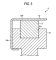
- FIG. 3 is a cross-sectional view of the frictional member 4 of the driving device, which is taken on line III-III shown in FIG. 1.
- the frictional member 4 includes, for example, a body portion 41 and a pressing member 42.
- the body portion 41 is pressed against the piezoelectric element 2 by a constant force of the pressing member 42.
- a concave portion 41a is formed in the body portion 41.
- the body portion 41 is disposed so that the piezoelectric element 2 abuts against the inner surface of the concave portion 41a.
- the frictional member 4 is disposed by utilizing the concave portion 41a. Consequently, the frictional member 4 can stably be mounted on the piezoelectric element 2.
- a cross-sectionally L-shaped plate spring member is used as the pressing member 42.
- One side of the pressing portion 42 is caught in the body portion 41.
- the other side of the pressing portion 42 is disposed at a place opposed to the inner surface of the concave portion 41a.
- the piezoelectric element 2 accommodated in the concave portion 41a can be sandwiched by the body portion 41 and the side 42b. Consequently, the body portion 41 can be pressed against the piezoelectric element 2.
- the body portion 41 is pressed by a constant force of the pressing portion 42 against the piezoelectric element 2.
- the frictional member 4 is frictionally engaged with the piezoelectric element 2. That is, the body portion 41 and the pressing portion 42 are pressed by a constant pressing force against the piezoelectric element 2.
- the frictional member 4 is mounted thereon so that when the frictional member 4 is moved, a constant frictional force is generated.
- an electrical signal is inputted to the piezoelectric element 2 is inputted.
- the piezoelectric element 2 iteratively expands and contracts in response to the input of the electrical signal.
- Electrical signals are used to cause the piezoelectric element 2 to expand and contract so that the expansion rate of the piezoelectric element 2 differs from the contraction rate thereof.
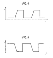
- pulse signals each of which is adapted so that a voltage rise rate (voltage increase rate) differs from a voltage drop rate (voltage decrease rate), are used as the electrical signals.
- the piezoelectric element 2 In a case where an electrical signal shown in FIG. 4 is inputted to the piezoelectric element 2, the voltage rise rate is low, while the voltage drop rate is high. Thus, the piezoelectric element 2 slowly expands and quickly contracts. At that time, the piezoelectric element 2 is movably supported by the support member 5. However, because the weight member 7 having a large weight is provided, the weight member 7 does not largely move in response to the expansion/contraction of the piezoelectric element 2. The piezoelectric element 2 expands to a side opposite to the weight member 7.
- the frictional member 4 moves together with the piezoelectric element 2. Conversely, when the piezoelectric element 2 quickly contracts toward the weight member 7, the frictional member 4 does not move together with the piezoelectric element 2 due to inertia. Therefore, when the piezoelectric element 2 repeats expansion and contraction, the frictional member 4 moves in a direction in which the frictional member 4 moves away from the weight member 7. Then, a moving lens provided integrally with the frictional member 4 is moved in a direction in which the moving lens moves away from the weight member 7.
- the frictional member 4 does not move together with the piezoelectric element 2 due to inertia. Conversely, when the piezoelectric element 2 slowly contacts toward the weight member 7, the frictional member 4 moves together with the piezoelectric element 2. Thus, when the piezoelectric element 2 iteratively expands and contracts, the frictional member 4 moves in a direction in which the frictional member 4 comes closer to the weight member 7. Also, the moving lens provided integrally with the frictional member 4 moves in a direction in which the moving lens comes loser to the weight member 7.
- the frictional member 4 and the moving lens can be moved and controlled by inputting predetermined electrical signals to the piezoelectric element 2.
- the frictional member 4 is frictionally engaged with the piezoelectric element 2 to be able to move along the longitudinal direction L of the piezoelectric element 2.
- the driving device according to the present invention does not need to have a driving frictional member as provided in the related device. Consequently, in the case of the driving device according to the invention, there is no need for bonding the driving frictional member to the electro-mechanical conversion element 2. This eliminates the fear of occurrence of deviation of the position of the driving frictional member with respect to the electro-mechanical conversion element. Consequently, the moving lens attached to the frictional member 4 can be moved with good precision.
- the device according to the invention is provided with no junction portion between the driving member and the piezoelectric member 2, which is provided therebetween in the related device. This eliminates the fear of damaging the device at the junction portion. Consequently, the impact strength can be enhanced. Also, the number of components is reduced. Thus, the cost of the device can be reduced. Additionally, the driving device of the invention is configured so that the piezoelectric element 2 also serves as the driving friction member provided in the related device. Thus, the miniaturization of the device can be achieved.
- FIG. 6 is a cross-sectional view illustrating the driving device according to the second embodiment of the invention.
- a driving device 51 according to the second embodiment differs from the driving device 1, which has the support member 5 and is configured to fix the one end of the piezoelectric element 2 to the stationary member 10, according to the first embodiment in that the driving device 51 has neither a support member nor a weight member and that one end of a piezoelectric element 2 is fixed to a stationary member 10.
- the one end of the piezoelectric element 2 is bonded to a wall 10a of the stationary member 10 with an adhesive agent.
- the driving device 51 according to the second embodiment can obtain advantages similar to those of the driving device 1 according to the first embodiment.
- each of the above embodiments is an example of the driving device according to the invention.
- the driving device according to the invention is not limited to those according to the above embodiments.
- the driving devices according to the embodiments may be modified or can be applied to other devices without departing from the spirit and scope of the invention.
- the driving device according to the invention applied to a device adapted to drive the moving lens has been described in the foregoing description of the embodiments, the driving device according to the invention may be applied to a device adapted to drive an element other than the moving lens.
- the above embodiments may be configured to have a position detection sensor adapted to detect the position of the frictional member 4 or the object to be moved.
- the movement of the frictional member 4 and the moving lens may be controlled according to position information outputted by the position detection sensor.
- the frictional member is mounted on the electro-mechanical conversion element.
- an obj ect to be moved can be moved with good accuracy.
- the impact strength can be enhanced.
Landscapes
- Physics & Mathematics (AREA)
- General Physics & Mathematics (AREA)
- Optics & Photonics (AREA)
- General Electrical Machinery Utilizing Piezoelectricity, Electrostriction Or Magnetostriction (AREA)
- Lens Barrels (AREA)
- Vehicle Body Suspensions (AREA)
- Brushes (AREA)
- Valve Device For Special Equipments (AREA)
Abstract
Description
- The present invention relates to a driving device using an electro-mechanical conversion element.
- Hitherto, a driving device employing a piezoelectric element (electro-mechanical conversion element), which is used to drive a lens of a digital camera or a camera phone, has been known. Such a driving device is configured so that one of end portions in the expansion/contraction direction of the piezoelectric element is fixed by a platform, and that a shaft-like driving frictional member extending in the expansion/contraction direction of the piezoelectric element is fixed to the other end portion of the piezoelectric element. A frictional engagement member capable of moving along the driving frictional member is mounted on the circumferential surface of the driving frictional member by being inserted thereon. The lens serving as a driven member is attached thereto through the frictional engagement member.
- In such a driving device, the piezoelectric element is expanded or contracted by applying a pulse-like voltage to the piezoelectric element. Thus, the driving frictional member moves. In a case where the piezoelectric element deforms at a low rate, the frictional engagement member moves together with the driving frictional member. In a case where the piezoelectric element deforms at a high rate, the frictional engagement member remains located at the same position due to inertia of the masses of the frictional engagement member and the driven member, whereas the driving frictional member moves. Therefore, the frictional engagement member frictionally engaged with the driving frictional member intermittently moves with fine pitches. Thus, the lens attached to the frictional engagement member can be moved (see, for example,
JP-A-2002-142470 - However, in this related driving device, it is difficult to position the electro-mechanical conversion element and the driving frictional member with good precision. Also, when the deviation of the position of the driving frictional member with respect to the electro-mechanical conversion element occurs, it is difficult to move an object, which is to be moved, with good precision.
- Also, in a case where an impact is applied to the related driving device due to the dropping thereof, a bonded portion between the electro-mechanical conversion element and the driving frictional member may be damaged.
- The invention is accomplished to solve the above problems. Accordingly, the invention aims at providing a driving device enabled to move an object, which is to be moved, with good precision and also enabled to enhance impact strength.
- According to the invention, there is provided a driving device comprising: an electro-mechanical conversion element enabled to expand and contract in response to input of an electrical signal; and a frictional member that is frictionally-engaged with the electro-mechanical conversion element and that is mounted on the electro-mechanical conversion element movably along a longitudinal direction of the electro-mechanical conversion element.
- According to such a driving device, the frictional member is frictionally engaged with the electro-mechanical conversion element so that the frictional member can move along the longitudinal direction of the electro-mechanical conversion element. Thus, this driving device does not need to have a driving frictional member as provided in the related driving device. Consequently, it is unnecessary to bond the driving frictional member and the electro-mechanical conversion element. Also, this eliminates fear of occurrence of deviation of the position of the driving frictional member with respect to the electro-mechanical conversion element. Consequently, the frictional member or an object to be moved, which is attached to the frictional member, can be moved with good precision. Additionally, the device according to the invention is provided with no junction portion between the driving member and the electro-mechanical conversion element, which is provided therebetween in the related device. This eliminates the fear of damaging the device at the junction portion. Consequently, the impact strength can be enhanced. Also, the number of components is reduced. Thus, the cost of the device can be reduced. Additionally, the driving device of the invention is configured so that the electro-mechanical conversion element also serves as the driving friction member provided in the related device. Thus, the miniaturization of the device can be achieved.
- Also, the driving device according to the invention may include a stationary member, wherein one end of the electro-mechanical conversion element is fixed to the stationary member.
- Also, the driving device according to the invention may include: a stationary member; a support member that supports the electro-mechanical conversion element with respect to the stationary member; and a weight member provided to be neither supported by nor fixed to the stationary member.
-
- FIG. 1 is a cross-sectional view illustrating a driving device according to a first embodiment of the invention;
- FIG. 2 is a cross-sectional view taken along the longitudinal direction of a piezoelectric element shown in FIG. 1;
- FIG. 3 is a cross-sectional view of a frictional member of the driving device, which is taken on line III-III shown in FIG. 1;
- FIG. 4 is an explanatory graph illustrating an electric signal inputted to the piezoelectric element of the driving device shown in FIG. 1;
- FIG. 5 is an explanatory graph illustrating another electric signal inputted to the piezoelectric element of the driving device shown in FIG. 1; and
- FIG. 6 is a cross-sectional view illustrating a driving device according to a second embodiment of the invention.
- Hereinafter, embodiments of the invention are described in detail by referring to the accompanying drawings. In the description with reference to the drawings, same reference numerals designate same elements. Thus, redundant description of such elements is omitted.
- FIG. 1 is a cross-sectional view illustrating a driving device according to a first embodiment of the invention.
- As shown in FIG. 1, a driving device 1 according to the present embodiment has a
piezoelectric element 2, africtional member 4, and asupport member 5. A moving lens (not shown) attached to thefrictional member 4 is employed as an object to be moved. Thus, the driving device 1 drives the moving lens. Thepiezoelectric element 2 is an electro-mechanical conversion element enabled to expand and contract in response to input of an electrical signal. Thus, thepiezoelectric element 2 can expand and contract in a predetermined direction. Thepiezoelectric element 2 is connected to a control portion (not shown), which inputs electrical signals to thepiezoelectric element 2 to thereby cause thepiezoelectric element 2 to expand and contract. For example, thepiezoelectric element 2 having two input terminals is used. Thepiezoelectric element 2 iteratively expands and contracts by repeatedly increasing and decreasing voltages to be inputted to the input terminals of thepiezoelectric element 2. - FIG. 2 is a cross-sectional view of the piezoelectric element, which is taken along the longitudinal direction of the piezoelectric element.
- As shown in FIG. 2, the
piezoelectric element 2 is formed by laminatinginternal electrodes External electrodes internal electrodes internal electrodes external electrodes input terminal 23 is provided in each of theexternal electrodes external electrodes resist 24 and aprotective coating 25. Thus, a sliding surface of thepiezoelectric element 2, on which thefrictional member 4 slides, is formed. - The
frictional member 4 is movably mounted on thepiezoelectric element 2, as shown in FIG. 1. Thefrictional member 4 is frictionally engaged with thepiezoelectric element 2 and is adapted to freely move along the longitudinal direction L. For example, thefrictional member 4 is engaged with thepiezoelectric element 2 with a predetermined frictional coefficient. Thefrictional member 4 is pressed against thepiezoelectric element 2 by a constant pressing force. Thus, thefrictional member 4 is mounted so that when thefrictional member 4 is moved, a constant frictional force is generated. Thefrictional member 4 is moved along thepiezoelectric element 2 against the frictional force by imparting a moving force, whose strength exceeds that of the frictional force, to thefrictional member 4. - The
piezoelectric element 2 is supported by astationary member 10 through thesupport member 5. Thesupport member 5 is constituted by a resin material that is filled between thepiezoelectric element 2 and thestationary member 10 and that is then hardened. An elastic deformation member adapted to elastically deform in response to the expansion/contraction of thepiezoelectric element 2 is used as the material of thesupport member 5. The material of the elastic deformation member is, for example, a silicon resin material. - The
support member 5 is disposed to cover the periphery of thepiezoelectric element 2. Although thesupport member 5 is shown at two places in FIG. 1, this figure shows the twocross-sections - The
stationary member 10 functions as a casing or a frame member, to which thepiezoelectric element 2 is assembled. In thestationary member 10,partition portions frictional member 4 is disposed, are formed. Throughholes piezoelectric element 2 is passed, are formed in thepartition portions - A
weight member 7 is attached to one of end portions of thepiezoelectric element 2. Theweight member 7 transmits the expanding/contracting force of thepiezoelectric element 2 to a side (the left side, as viewed in FIG. 1) opposite to theweight member 7. Preferably, a member obtained by mixing metal powder into an elastically deformable material is used as theweight member 7. The weight of themember 7 can be increased by mixing metal powder thereinto. The use of the elastically deformable member enables the attenuation of unnecessary resonance caused by an operation of thepiezoelectric element 2. - The
weight member 7 is provided to be neither supported by nor fixed to thestationary member 10. That is, theweight member 7 is neither supported directly by nor fixed directly to thestationary member 10. Also, theweight member 7 is neither supported by nor fixed to thestationary member 10 through an adhesive agent or a resin material so that the movement of theweight member 7 is restrained. - FIG. 3 is a cross-sectional view of the
frictional member 4 of the driving device, which is taken on line III-III shown in FIG. 1. - As shown in FIG. 3, the
frictional member 4 includes, for example, abody portion 41 and a pressingmember 42. Thebody portion 41 is pressed against thepiezoelectric element 2 by a constant force of the pressingmember 42. Aconcave portion 41a is formed in thebody portion 41. Thebody portion 41 is disposed so that thepiezoelectric element 2 abuts against the inner surface of theconcave portion 41a. Thus, thefrictional member 4 is disposed by utilizing theconcave portion 41a. Consequently, thefrictional member 4 can stably be mounted on thepiezoelectric element 2. - For example, a cross-sectionally L-shaped plate spring member is used as the pressing
member 42. One side of thepressing portion 42 is caught in thebody portion 41. The other side of thepressing portion 42 is disposed at a place opposed to the inner surface of theconcave portion 41a. Thus, thepiezoelectric element 2 accommodated in theconcave portion 41a can be sandwiched by thebody portion 41 and theside 42b. Consequently, thebody portion 41 can be pressed against thepiezoelectric element 2. - Thus, the
body portion 41 is pressed by a constant force of thepressing portion 42 against thepiezoelectric element 2. Thus, thefrictional member 4 is frictionally engaged with thepiezoelectric element 2. That is, thebody portion 41 and thepressing portion 42 are pressed by a constant pressing force against thepiezoelectric element 2. Thefrictional member 4 is mounted thereon so that when thefrictional member 4 is moved, a constant frictional force is generated. - Next, a basic action of the driving device 1 according to the present embodiment is described below.
- As shown in FIG. 1, an electrical signal is inputted to the
piezoelectric element 2 is inputted. Thepiezoelectric element 2 iteratively expands and contracts in response to the input of the electrical signal. Electrical signals are used to cause thepiezoelectric element 2 to expand and contract so that the expansion rate of thepiezoelectric element 2 differs from the contraction rate thereof. For example, as illustrated in FIGS. 4 and 5, pulse signals, each of which is adapted so that a voltage rise rate (voltage increase rate) differs from a voltage drop rate (voltage decrease rate), are used as the electrical signals. - In a case where an electrical signal shown in FIG. 4 is inputted to the
piezoelectric element 2, the voltage rise rate is low, while the voltage drop rate is high. Thus, thepiezoelectric element 2 slowly expands and quickly contracts. At that time, thepiezoelectric element 2 is movably supported by thesupport member 5. However, because theweight member 7 having a large weight is provided, theweight member 7 does not largely move in response to the expansion/contraction of thepiezoelectric element 2. Thepiezoelectric element 2 expands to a side opposite to theweight member 7. - As the
piezoelectric element 2 slowly expands to the opposite to theweight member 7, thefrictional member 4 moves together with thepiezoelectric element 2. Conversely, when thepiezoelectric element 2 quickly contracts toward theweight member 7, thefrictional member 4 does not move together with thepiezoelectric element 2 due to inertia. Therefore, when thepiezoelectric element 2 repeats expansion and contraction, thefrictional member 4 moves in a direction in which thefrictional member 4 moves away from theweight member 7. Then, a moving lens provided integrally with thefrictional member 4 is moved in a direction in which the moving lens moves away from theweight member 7. - In contrast, in a case where an electrical signal shown in FIG. 5 is inputted to the
piezoelectric element 2, the voltage rise rate is high, while the voltage drop rate is low. Thus, thepiezoelectric element 2 quickly expands and slowly contracts. - At that time, even in a case where the
piezoelectric element 2 quickly expands to the side opposite to theweight member 7, thefrictional member 4 does not move together with thepiezoelectric element 2 due to inertia. Conversely, when thepiezoelectric element 2 slowly contacts toward theweight member 7, thefrictional member 4 moves together with thepiezoelectric element 2. Thus, when thepiezoelectric element 2 iteratively expands and contracts, thefrictional member 4 moves in a direction in which thefrictional member 4 comes closer to theweight member 7. Also, the moving lens provided integrally with thefrictional member 4 moves in a direction in which the moving lens comes loser to theweight member 7. - Thus, the
frictional member 4 and the moving lens can be moved and controlled by inputting predetermined electrical signals to thepiezoelectric element 2. - As described above, in accordance with the driving device 1 according to the present embodiment, the
frictional member 4 is frictionally engaged with thepiezoelectric element 2 to be able to move along the longitudinal direction L of thepiezoelectric element 2. Thus, the driving device according to the present invention does not need to have a driving frictional member as provided in the related device. Consequently, in the case of the driving device according to the invention, there is no need for bonding the driving frictional member to the electro-mechanical conversion element 2. This eliminates the fear of occurrence of deviation of the position of the driving frictional member with respect to the electro-mechanical conversion element. Consequently, the moving lens attached to thefrictional member 4 can be moved with good precision. Additionally, the device according to the invention is provided with no junction portion between the driving member and thepiezoelectric member 2, which is provided therebetween in the related device. This eliminates the fear of damaging the device at the junction portion. Consequently, the impact strength can be enhanced. Also, the number of components is reduced. Thus, the cost of the device can be reduced. Additionally, the driving device of the invention is configured so that thepiezoelectric element 2 also serves as the driving friction member provided in the related device. Thus, the miniaturization of the device can be achieved. - Next, a driving device according to a second embodiment of the invention is described below.
- FIG. 6 is a cross-sectional view illustrating the driving device according to the second embodiment of the invention. A driving
device 51 according to the second embodiment differs from the driving device 1, which has thesupport member 5 and is configured to fix the one end of thepiezoelectric element 2 to thestationary member 10, according to the first embodiment in that the drivingdevice 51 has neither a support member nor a weight member and that one end of apiezoelectric element 2 is fixed to astationary member 10. In the drivingdevice 51 according to the second embodiment, the one end of thepiezoelectric element 2 is bonded to awall 10a of thestationary member 10 with an adhesive agent. With this configuration, the drivingdevice 51 according to the second embodiment can obtain advantages similar to those of the driving device 1 according to the first embodiment. - Incidentally, each of the above embodiments is an example of the driving device according to the invention. The driving device according to the invention is not limited to those according to the above embodiments. The driving devices according to the embodiments may be modified or can be applied to other devices without departing from the spirit and scope of the invention. Although the driving device according to the invention applied to a device adapted to drive the moving lens has been described in the foregoing description of the embodiments, the driving device according to the invention may be applied to a device adapted to drive an element other than the moving lens.
- Additionally, the above embodiments may be configured to have a position detection sensor adapted to detect the position of the
frictional member 4 or the object to be moved. The movement of thefrictional member 4 and the moving lens may be controlled according to position information outputted by the position detection sensor. - According to the driving apparatus of the invention, the frictional member is mounted on the electro-mechanical conversion element. Thus, an obj ect to be moved can be moved with good accuracy. Also, the impact strength can be enhanced.
- The entire disclosure of each and every foreign patent application from which the benefit of foreign priority has been claimed in the present application is incorporated herein by reference, as if fully set forth.
Claims (3)
- A driving device comprising:an electro-mechanical conversion element enabled to expand and contract in response to input of an electrical signal; anda frictional member that is frictionally-engaged with the electro-mechanical conversion element and that is mounted on the electro-mechanical conversion element movably along a longitudinal direction of the electro-mechanical conversion element.
- The driving device according to claim 1, further comprising a stationary member,
wherein one end of the electro-mechanical conversion element is fixed to the stationary member. - The driving device according to claim 1, further comprising:a stationary member;a support member that supports the electro-mechanical conversion element with respect to the stationary member; anda weight member that is neither supported by nor fixed to the stationary member.
Applications Claiming Priority (1)
| Application Number | Priority Date | Filing Date | Title |
|---|---|---|---|
| JP2005338940A JP2007151238A (en) | 2005-11-24 | 2005-11-24 | Drive device |
Publications (2)
| Publication Number | Publication Date |
|---|---|
| EP1791194A1 true EP1791194A1 (en) | 2007-05-30 |
| EP1791194B1 EP1791194B1 (en) | 2009-07-08 |
Family
ID=37671253
Family Applications (1)
| Application Number | Title | Priority Date | Filing Date |
|---|---|---|---|
| EP20060024228 Not-in-force EP1791194B1 (en) | 2005-11-24 | 2006-11-22 | Driving device |
Country Status (6)
| Country | Link |
|---|---|
| US (1) | US7504761B2 (en) |
| EP (1) | EP1791194B1 (en) |
| JP (1) | JP2007151238A (en) |
| CN (1) | CN1972104A (en) |
| AT (1) | ATE436095T1 (en) |
| DE (1) | DE602006007659D1 (en) |
Families Citing this family (2)
| Publication number | Priority date | Publication date | Assignee | Title |
|---|---|---|---|---|
| JP2007104761A (en) * | 2005-09-30 | 2007-04-19 | Fujinon Corp | Actuator |
| JP5556857B2 (en) * | 2012-06-22 | 2014-07-23 | Tdk株式会社 | Multilayer piezoelectric element |
Citations (2)
| Publication number | Priority date | Publication date | Assignee | Title |
|---|---|---|---|---|
| US6134057A (en) * | 1997-09-17 | 2000-10-17 | Minolta Co., Ltd. | Drive and guide mechanism and apparatus using the mechanism |
| WO2006099924A1 (en) * | 2005-03-21 | 2006-09-28 | Physik Instrumente (Pi) Gmbh & Co. Kg | Optical objective module |
Family Cites Families (10)
| Publication number | Priority date | Publication date | Assignee | Title |
|---|---|---|---|---|
| US3246608A (en) * | 1964-01-13 | 1966-04-19 | Richard C Cooper | Conveyor system |
| JPS529388A (en) * | 1975-07-11 | 1977-01-24 | Seiko Epson Corp | Electricity generator |
| US4630941A (en) * | 1984-02-21 | 1986-12-23 | International Business Machines Corp. | Tubular squeeze bearing apparatus with rotational restraint |
| JPS61154487A (en) * | 1984-12-26 | 1986-07-14 | Canon Inc | linear vibration wave motor |
| EP0415657A3 (en) * | 1989-08-31 | 1991-12-04 | Kohji Toda | Vibrator-type actuator |
| JPH0670565A (en) * | 1992-08-18 | 1994-03-11 | Olympus Optical Co Ltd | Ultrasonic oscillator and ultrasonic actuator |
| JPH06141564A (en) * | 1992-10-28 | 1994-05-20 | Nikon Corp | Wave circulation type actuator |
| US6140750A (en) * | 1997-04-14 | 2000-10-31 | Minolta Co., Ltd. | Actuator using electromechanical transducer and apparatus employing the actuator |
| JP4154851B2 (en) | 2000-10-31 | 2008-09-24 | コニカミノルタホールディングス株式会社 | Drive device |
| JP4742519B2 (en) | 2004-05-14 | 2011-08-10 | コニカミノルタオプト株式会社 | Drive device using electromechanical transducer |
-
2005
- 2005-11-24 JP JP2005338940A patent/JP2007151238A/en not_active Withdrawn
-
2006
- 2006-11-17 CN CNA2006101494589A patent/CN1972104A/en active Pending
- 2006-11-22 AT AT06024228T patent/ATE436095T1/en not_active IP Right Cessation
- 2006-11-22 DE DE200660007659 patent/DE602006007659D1/en active Active
- 2006-11-22 EP EP20060024228 patent/EP1791194B1/en not_active Not-in-force
- 2006-11-22 US US11/603,132 patent/US7504761B2/en not_active Expired - Fee Related
Patent Citations (2)
| Publication number | Priority date | Publication date | Assignee | Title |
|---|---|---|---|---|
| US6134057A (en) * | 1997-09-17 | 2000-10-17 | Minolta Co., Ltd. | Drive and guide mechanism and apparatus using the mechanism |
| WO2006099924A1 (en) * | 2005-03-21 | 2006-09-28 | Physik Instrumente (Pi) Gmbh & Co. Kg | Optical objective module |
Also Published As
| Publication number | Publication date |
|---|---|
| US7504761B2 (en) | 2009-03-17 |
| US20070114888A1 (en) | 2007-05-24 |
| DE602006007659D1 (en) | 2009-08-20 |
| ATE436095T1 (en) | 2009-07-15 |
| EP1791194B1 (en) | 2009-07-08 |
| JP2007151238A (en) | 2007-06-14 |
| CN1972104A (en) | 2007-05-30 |
Similar Documents
| Publication | Publication Date | Title |
|---|---|---|
| JP6155460B2 (en) | Drive member, linear drive device, camera device, and electronic device | |
| US20070228885A1 (en) | Driving apparatus | |
| US20130169854A1 (en) | Camera module, electronic device comprising the same and auto focus method | |
| EP3442109A1 (en) | Actuator and tactile sensation presentation device | |
| US7956513B2 (en) | Method of driving a driving device | |
| EP1753042B1 (en) | Actuator | |
| JP4936511B2 (en) | Driving device, photographing device and mobile phone | |
| EP1770420B1 (en) | Actuator | |
| KR100777634B1 (en) | Driving mechanism | |
| JP7313909B2 (en) | vibration wave motors and electronics. | |
| US7652407B2 (en) | Driving device capable of improving a shock and vibration resistance thereof | |
| KR100777636B1 (en) | Driving mechanism, imaging mechanism and cellular phone | |
| EP1791194B1 (en) | Driving device | |
| US9455394B2 (en) | Displacement member, driving member, actuator, and driving device | |
| EP1753044A2 (en) | Actuator | |
| EP1753041A2 (en) | Actuator | |
| US7403342B2 (en) | Lens device | |
| JP5280915B2 (en) | Electromechanical motor | |
| JP2008245467A (en) | Drive device | |
| EP1791248A2 (en) | Driving device | |
| JP2006154390A (en) | Lens driving device, and imaging apparatus | |
| JP4906326B2 (en) | Drive device and drive device manufacturing method | |
| JP2008253021A (en) | Drive device | |
| EP1753121A2 (en) | Actuator | |
| JP2005218158A (en) | Piezoelectric actuator and control system using the same |
Legal Events
| Date | Code | Title | Description |
|---|---|---|---|
| PUAI | Public reference made under article 153(3) epc to a published international application that has entered the european phase |
Free format text: ORIGINAL CODE: 0009012 |
|
| 17P | Request for examination filed |
Effective date: 20061122 |
|
| AK | Designated contracting states |
Kind code of ref document: A1 Designated state(s): AT BE BG CH CY CZ DE DK EE ES FI FR GB GR HU IE IS IT LI LT LU LV MC NL PL PT RO SE SI SK TR |
|
| AX | Request for extension of the european patent |
Extension state: AL BA HR MK YU |
|
| 17Q | First examination report despatched |
Effective date: 20071221 |
|
| AKX | Designation fees paid |
Designated state(s): AT BE BG CH CY CZ DE DK EE ES FI FR GB GR HU IE IS IT LI LT LU LV MC NL PL PT RO SE SI SK TR |
|
| GRAP | Despatch of communication of intention to grant a patent |
Free format text: ORIGINAL CODE: EPIDOSNIGR1 |
|
| RIN1 | Information on inventor provided before grant (corrected) |
Inventor name: TOKUMIYA, MOTOYOSHI |
|
| GRAS | Grant fee paid |
Free format text: ORIGINAL CODE: EPIDOSNIGR3 |
|
| GRAA | (expected) grant |
Free format text: ORIGINAL CODE: 0009210 |
|
| AK | Designated contracting states |
Kind code of ref document: B1 Designated state(s): AT BE BG CH CY CZ DE DK EE ES FI FR GB GR HU IE IS IT LI LT LU LV MC NL PL PT RO SE SI SK TR |
|
| REG | Reference to a national code |
Ref country code: GB Ref legal event code: FG4D |
|
| REG | Reference to a national code |
Ref country code: CH Ref legal event code: EP |
|
| REG | Reference to a national code |
Ref country code: IE Ref legal event code: FG4D |
|
| REF | Corresponds to: |
Ref document number: 602006007659 Country of ref document: DE Date of ref document: 20090820 Kind code of ref document: P |
|
| PG25 | Lapsed in a contracting state [announced via postgrant information from national office to epo] |
Ref country code: SI Free format text: LAPSE BECAUSE OF FAILURE TO SUBMIT A TRANSLATION OF THE DESCRIPTION OR TO PAY THE FEE WITHIN THE PRESCRIBED TIME-LIMIT Effective date: 20090708 |
|
| NLV1 | Nl: lapsed or annulled due to failure to fulfill the requirements of art. 29p and 29m of the patents act | ||
| PG25 | Lapsed in a contracting state [announced via postgrant information from national office to epo] |
Ref country code: ES Free format text: LAPSE BECAUSE OF FAILURE TO SUBMIT A TRANSLATION OF THE DESCRIPTION OR TO PAY THE FEE WITHIN THE PRESCRIBED TIME-LIMIT Effective date: 20091019 Ref country code: AT Free format text: LAPSE BECAUSE OF FAILURE TO SUBMIT A TRANSLATION OF THE DESCRIPTION OR TO PAY THE FEE WITHIN THE PRESCRIBED TIME-LIMIT Effective date: 20090708 Ref country code: LT Free format text: LAPSE BECAUSE OF FAILURE TO SUBMIT A TRANSLATION OF THE DESCRIPTION OR TO PAY THE FEE WITHIN THE PRESCRIBED TIME-LIMIT Effective date: 20090708 Ref country code: FI Free format text: LAPSE BECAUSE OF FAILURE TO SUBMIT A TRANSLATION OF THE DESCRIPTION OR TO PAY THE FEE WITHIN THE PRESCRIBED TIME-LIMIT Effective date: 20090708 Ref country code: IS Free format text: LAPSE BECAUSE OF FAILURE TO SUBMIT A TRANSLATION OF THE DESCRIPTION OR TO PAY THE FEE WITHIN THE PRESCRIBED TIME-LIMIT Effective date: 20091108 |
|
| PG25 | Lapsed in a contracting state [announced via postgrant information from national office to epo] |
Ref country code: NL Free format text: LAPSE BECAUSE OF FAILURE TO SUBMIT A TRANSLATION OF THE DESCRIPTION OR TO PAY THE FEE WITHIN THE PRESCRIBED TIME-LIMIT Effective date: 20090708 Ref country code: PL Free format text: LAPSE BECAUSE OF FAILURE TO SUBMIT A TRANSLATION OF THE DESCRIPTION OR TO PAY THE FEE WITHIN THE PRESCRIBED TIME-LIMIT Effective date: 20090708 Ref country code: LV Free format text: LAPSE BECAUSE OF FAILURE TO SUBMIT A TRANSLATION OF THE DESCRIPTION OR TO PAY THE FEE WITHIN THE PRESCRIBED TIME-LIMIT Effective date: 20090708 |
|
| PG25 | Lapsed in a contracting state [announced via postgrant information from national office to epo] |
Ref country code: PT Free format text: LAPSE BECAUSE OF FAILURE TO SUBMIT A TRANSLATION OF THE DESCRIPTION OR TO PAY THE FEE WITHIN THE PRESCRIBED TIME-LIMIT Effective date: 20091109 Ref country code: BG Free format text: LAPSE BECAUSE OF FAILURE TO SUBMIT A TRANSLATION OF THE DESCRIPTION OR TO PAY THE FEE WITHIN THE PRESCRIBED TIME-LIMIT Effective date: 20091008 |
|
| PG25 | Lapsed in a contracting state [announced via postgrant information from national office to epo] |
Ref country code: DK Free format text: LAPSE BECAUSE OF FAILURE TO SUBMIT A TRANSLATION OF THE DESCRIPTION OR TO PAY THE FEE WITHIN THE PRESCRIBED TIME-LIMIT Effective date: 20090708 Ref country code: EE Free format text: LAPSE BECAUSE OF FAILURE TO SUBMIT A TRANSLATION OF THE DESCRIPTION OR TO PAY THE FEE WITHIN THE PRESCRIBED TIME-LIMIT Effective date: 20090708 Ref country code: RO Free format text: LAPSE BECAUSE OF FAILURE TO SUBMIT A TRANSLATION OF THE DESCRIPTION OR TO PAY THE FEE WITHIN THE PRESCRIBED TIME-LIMIT Effective date: 20090708 Ref country code: CZ Free format text: LAPSE BECAUSE OF FAILURE TO SUBMIT A TRANSLATION OF THE DESCRIPTION OR TO PAY THE FEE WITHIN THE PRESCRIBED TIME-LIMIT Effective date: 20090708 |
|
| PLBE | No opposition filed within time limit |
Free format text: ORIGINAL CODE: 0009261 |
|
| STAA | Information on the status of an ep patent application or granted ep patent |
Free format text: STATUS: NO OPPOSITION FILED WITHIN TIME LIMIT |
|
| PG25 | Lapsed in a contracting state [announced via postgrant information from national office to epo] |
Ref country code: BE Free format text: LAPSE BECAUSE OF FAILURE TO SUBMIT A TRANSLATION OF THE DESCRIPTION OR TO PAY THE FEE WITHIN THE PRESCRIBED TIME-LIMIT Effective date: 20090708 Ref country code: SK Free format text: LAPSE BECAUSE OF FAILURE TO SUBMIT A TRANSLATION OF THE DESCRIPTION OR TO PAY THE FEE WITHIN THE PRESCRIBED TIME-LIMIT Effective date: 20090708 |
|
| 26N | No opposition filed |
Effective date: 20100409 |
|
| PG25 | Lapsed in a contracting state [announced via postgrant information from national office to epo] |
Ref country code: MC Free format text: LAPSE BECAUSE OF NON-PAYMENT OF DUE FEES Effective date: 20091130 |
|
| REG | Reference to a national code |
Ref country code: FR Ref legal event code: ST Effective date: 20100730 |
|
| PG25 | Lapsed in a contracting state [announced via postgrant information from national office to epo] |
Ref country code: GR Free format text: LAPSE BECAUSE OF FAILURE TO SUBMIT A TRANSLATION OF THE DESCRIPTION OR TO PAY THE FEE WITHIN THE PRESCRIBED TIME-LIMIT Effective date: 20091009 Ref country code: IE Free format text: LAPSE BECAUSE OF NON-PAYMENT OF DUE FEES Effective date: 20091122 Ref country code: FR Free format text: LAPSE BECAUSE OF NON-PAYMENT OF DUE FEES Effective date: 20091130 |
|
| PGFP | Annual fee paid to national office [announced via postgrant information from national office to epo] |
Ref country code: DE Payment date: 20101027 Year of fee payment: 5 |
|
| PG25 | Lapsed in a contracting state [announced via postgrant information from national office to epo] |
Ref country code: IT Free format text: LAPSE BECAUSE OF FAILURE TO SUBMIT A TRANSLATION OF THE DESCRIPTION OR TO PAY THE FEE WITHIN THE PRESCRIBED TIME-LIMIT Effective date: 20090708 |
|
| PG25 | Lapsed in a contracting state [announced via postgrant information from national office to epo] |
Ref country code: LU Free format text: LAPSE BECAUSE OF NON-PAYMENT OF DUE FEES Effective date: 20091122 |
|
| PG25 | Lapsed in a contracting state [announced via postgrant information from national office to epo] |
Ref country code: HU Free format text: LAPSE BECAUSE OF FAILURE TO SUBMIT A TRANSLATION OF THE DESCRIPTION OR TO PAY THE FEE WITHIN THE PRESCRIBED TIME-LIMIT Effective date: 20100109 |
|
| REG | Reference to a national code |
Ref country code: CH Ref legal event code: PL |
|
| GBPC | Gb: european patent ceased through non-payment of renewal fee |
Effective date: 20101122 |
|
| PG25 | Lapsed in a contracting state [announced via postgrant information from national office to epo] |
Ref country code: LI Free format text: LAPSE BECAUSE OF NON-PAYMENT OF DUE FEES Effective date: 20101130 Ref country code: CH Free format text: LAPSE BECAUSE OF NON-PAYMENT OF DUE FEES Effective date: 20101130 |
|
| PG25 | Lapsed in a contracting state [announced via postgrant information from national office to epo] |
Ref country code: TR Free format text: LAPSE BECAUSE OF FAILURE TO SUBMIT A TRANSLATION OF THE DESCRIPTION OR TO PAY THE FEE WITHIN THE PRESCRIBED TIME-LIMIT Effective date: 20090708 |
|
| PG25 | Lapsed in a contracting state [announced via postgrant information from national office to epo] |
Ref country code: CY Free format text: LAPSE BECAUSE OF FAILURE TO SUBMIT A TRANSLATION OF THE DESCRIPTION OR TO PAY THE FEE WITHIN THE PRESCRIBED TIME-LIMIT Effective date: 20090708 |
|
| PG25 | Lapsed in a contracting state [announced via postgrant information from national office to epo] |
Ref country code: GB Free format text: LAPSE BECAUSE OF NON-PAYMENT OF DUE FEES Effective date: 20101122 |
|
| REG | Reference to a national code |
Ref country code: DE Ref legal event code: R119 Ref document number: 602006007659 Country of ref document: DE Effective date: 20120601 |
|
| PG25 | Lapsed in a contracting state [announced via postgrant information from national office to epo] |
Ref country code: SE Free format text: LAPSE BECAUSE OF FAILURE TO SUBMIT A TRANSLATION OF THE DESCRIPTION OR TO PAY THE FEE WITHIN THE PRESCRIBED TIME-LIMIT Effective date: 20090708 |
|
| PG25 | Lapsed in a contracting state [announced via postgrant information from national office to epo] |
Ref country code: DE Free format text: LAPSE BECAUSE OF NON-PAYMENT OF DUE FEES Effective date: 20120601 |