EP1791058A1 - A system having an energy efficient network infrastructure for communication between distributed processing nodes - Google Patents
A system having an energy efficient network infrastructure for communication between distributed processing nodes Download PDFInfo
- Publication number
- EP1791058A1 EP1791058A1 EP06077069A EP06077069A EP1791058A1 EP 1791058 A1 EP1791058 A1 EP 1791058A1 EP 06077069 A EP06077069 A EP 06077069A EP 06077069 A EP06077069 A EP 06077069A EP 1791058 A1 EP1791058 A1 EP 1791058A1
- Authority
- EP
- European Patent Office
- Prior art keywords
- message
- application
- thread
- identifier
- data processing
- Prior art date
- Legal status (The legal status is an assumption and is not a legal conclusion. Google has not performed a legal analysis and makes no representation as to the accuracy of the status listed.)
- Granted
Links
Images







Classifications
-
- G—PHYSICS
- G06—COMPUTING OR CALCULATING; COUNTING
- G06F—ELECTRIC DIGITAL DATA PROCESSING
- G06F9/00—Arrangements for program control, e.g. control units
- G06F9/06—Arrangements for program control, e.g. control units using stored programs, i.e. using an internal store of processing equipment to receive or retain programs
- G06F9/46—Multiprogramming arrangements
- G06F9/54—Interprogram communication
- G06F9/546—Message passing systems or structures, e.g. queues
-
- H—ELECTRICITY
- H04—ELECTRIC COMMUNICATION TECHNIQUE
- H04L—TRANSMISSION OF DIGITAL INFORMATION, e.g. TELEGRAPHIC COMMUNICATION
- H04L45/00—Routing or path finding of packets in data switching networks
- H04L45/302—Route determination based on requested QoS
Definitions
- the method further comprises determining whether the destination application identifier corresponds to one of the assigned application identifiers in the routing table, and, when it is determined that the destination application identifier corresponds to one of the assigned application identifiers in the routing table, notifying the command thread of the application corresponding to the destination application identifier that the received message is available for access.
- Each data processing node 102a and 102n also includes a memory 108, a secondary storage device 110 an input/output (I/O) unit 112, and a power source 113, such as a battery, each of which is operatively connected to the CPU 106 via a local bus or backplane 114.
- the secondary storage may be a non-volatile RAM, a fixed or removable hard disk, a read/write CD, or any other non-volatile memory device.
- the I/O unit 112 may comprise discrete external hardware components (e.g., D/A converters, address/data transceivers, receiver, transmitter, modem, bus/network drivers, or other I/O components) for interfacing with external systems or devices 50-58 in Fig. 1A, such as a thermal or radiation sensor, an antenna, actuator, altimeter, keyboard, display 115, or other device that may be controlled by an application running on the respective data processing node 102a and 102n in accordance with the present invention.
- Memory 108 in each data processing node 102a and 102n stores one or more applications 118, 120, 122, and 124, an application communications manager 126 or 128, and an operating system 130.
- the operating system 130 may be VxWorks TM , LynxOS ® , Solaris TM or other operating system having a plurality of programmable events or interrupts that allow process control to be transferred to a corresponding event handler associated with a thread (e.g., command thread 156a-156d in Fig. 1B of one of the applications 118, 120, 122, and 124 when the respective event is triggered by one of the threads (e.g., application message routing thread 132) of the application communications manager 126 or 128.
- a thread e.g., command thread 156a-156d in Fig. 1B of one of the applications 118, 120, 122, and 124 when the respective event is triggered by one of the threads (e.g., application message routing thread 132) of the application
- the main thread 148b of the other application 120 may then submit the processed target detection data across the network in one or more messages to the requesting application 122 (via the command thread 156c and the applications communications manager 128).
- the main thread 148a and the command thread 156a of the application 118 may not be required to operate (e.g., both enter a sleep state) until triggered to "wake up” and respond to the command (e.g., to sense for airborne targets) sent from the application 122.
- the message 202 depicts the exemplary structure of a message 202 that may be transmitted by a first application (e.g., 118) to a second application (e.g., 122) via the routing threads 132 residing on the same nodes 102a and 102n as the first and second applications 118 and 122.
- the message 202 includes a message header 204 and a message body 206.
- the message header 204 includes a source location 208 and a destination location 210.
- the source location 208 includes an application identifier ("ID") 212 assigned to the first application 118 that transmitted the message 202.
- the source location also includes a message group ID 214 and a function or message ID 216.
- Each application 118, 120, 122, or 124 may be programmed to call a save function (not shown in the figures) that saves the saveable portion 404 of the local blackboard 152a, 152b, 152c, and 152d so that the saveable portion may be later restored.
- a save function (not shown in the figures) that saves the saveable portion 404 of the local blackboard 152a, 152b, 152c, and 152d so that the saveable portion may be later restored.
- each application communications manager 126 and 128 also includes a load and registration service thread 136 that is operatively configured to load each application 118, 120, 122, 124 from secondary storage 110 into memory 108, define the order each application 118, 120, 122, 124 is to register to the system 100, and initiate execution of the applications 118, 120, 122, and 124 in accordance with an architecture configuration file 138 as discussed in detail below.
- the load and registration thread 136 is initially called by the boot-up program 117.
- Each application communication manager 126 and 128 may also include a health service thread 140, a file service thread 142, and an alarm service thread 144.
- the health service thread 140 is a system 100 function that may be called by one application (e.g., 118) on one node 102a to identify the health of another application (e.g., 122) on another node 102n in the data processing system 100.
- the health service thread 140 will return an alive status or heartbeat identifier if the other application (e.g., 122) is loaded in memory 108 and running.
- the file service thread 142 comprises a plurality of file operations shown in Table I below that an application 118, 120, 122, and 124 may use to access or manipulate a file (not shown in Fig. 1B) in memory 108 or secondary storage 110.
- Each file operation is defined to replace corresponding operating system 130 functions in order to enforce source code and compiled code commonality between applications 118, 120, 122, and 124 in order to minimize unnecessary data movement and CPU 106 cycles associated with file access and manipulation.
- Table I 1. file open 2. file close 3. file write 4. file read 5. file verify 6. file delete 7. file rename 8. file copy 9. file append 10. file delta
- the alarm service thread 144 comprises a system 100 function that may be called by one application (e.g., 118) to signal an alarm event to another application (e.g., 122) over the network 104 without having to go through a central application to broadcast the alarm event.
- one application e.g., 118
- another application e.g., 122
- the message handler type definition 502 provides an application 118, 120, 122, and 124 with a common interface (e.g., 510, 512, and 514) for handling an event raised by one or more of the service threads (e.g., 140, 142, and 144) of the application communication manager 126 or 128 for the respective application 118, 120, 122, and 124.
- the message input queue (“MsgInputQueue") 506 defines the storage block in which the application message routing thread 132 stores a pointer to each message received by the application message routing thread 132 for the respective application. In one implementation, the message input queue is defined to be a FIFO type buffer.
- the application API 146 also includes a send message function 516 that may be used by the command thread 508 to process a message for output to the application message routing thread 132 and a receive message function 518 to process a message identified by a pointer stored in the queue 506.
- the application API 146 may also include a hardware control thread 520 function that includes a hardware output control function 522 for controlling discrete external hardware components of the I/O unit 112 associated with the respective application 118, 120, 122, or 124.
- the hardware control thread 520 may also include a hardware input function 524 for receiving data discrete external hardware components of the I/O unit 112 associated with the respective application 118, 120, 122, or 124 and storing the data in a buffer defined by the input buffer type 526.
- each application 118, 120, 122, or 124 may be required to support the "sovol_msg_alive" command message 611 as shown in Fig. 6 which may be invoked by the health service thread 140 to identify the health (e.g., "alive") of the application (e.g., 118) on a periodic basis or in response to a request from another node 102n in the data processing system 100.
- the health service thread 140 may be invoked by the health service thread 140 to identify the health (e.g., "alive" of the application (e.g., 118) on a periodic basis or in response to a request from another node 102n in the data processing system 100.
- Each message definition subsection 704 and 706 identifies respective messages to be associated with the message group identified by the tag 602.
- each message definition subsection 704 and 706 includes a message or function name 708 or other identifier, an argument identifier 710 and associated argument type 712, and a message body 714.
- each message group section 702 is used to generate a message group table 808 in Fig. 8 that may be accessed by each of the applications 118, 120, 122, and 124 to respond to or process a message 202 in accordance with the present invention.
- each message 202 or 708 may be associated with a message group 702 once in one application definition file (e.g., 160a) or in a separate message definition file (not shown in figures).
- each main thread definition 606 includes one or more callback definitions 612 and 614, each of which corresponds to a function 613 or 615 performed by the thread services 136, 140, 142, or 144 or the operating system 130 and that may be invoked by the associated main thread (e.g., 148a, 148b, 148c, or 148d) during runtime.
- Each callback function 613 or 615 is operatively configured to allow the program control to be returned to the respective main thread.
- Each command thread definition 608 includes a thread identifier tag 616 set to a name (e.g., "cmd") or other identifier to signal that the thread definition 608 is for a command thread 156a, 156b, 156c, or 156d.
- Other thread definitions may be provided in a format similar to the command thread definition 608 to define other threads.
- the thread identifier tag 616 may be set to another name (“e.g., H/W”) to identify the other thread (e.g., the H/W control thread 158a).
- the identified event handler 620 corresponds to one of the message group handlers (e.g., 150aa, 150ba, 150ca, or 150da) defined for the respective application 118, 120, 122, or 124, which is called by the command thread 156a, 156b, 156c, or 156d for processing in accordance with the present invention.
- the message group handlers e.g., 150aa, 150ba, 150ca, or 150da
- the definition-to-source code translator 802 may be an XML parser/XSLT (extensible Stylesheet Language Translator) processor program (such as "cygwin” TM " available at www.cygwin.com) that uses one or more Stylesheets operatively configured to translate application definition files 160a, 160b, 160c, and 160d to corresponding source code in accordance with the application API 146 of the applications communication manager 126 and 128.
- the development computer system 800 also includes a compiler/linker 806 compiling and linking the source code 804a-d for the applications 118, 120, 122, and 124 with a library of compiled application communication manager threads 805 in accordance with a makefile 807.
- the message group table 808 and the message tables 810a-810n may be built during compile time by or runtime by the load and registration service thread 136 from each message group definition (e.g., section 702 of application definitions 160a, 160b, 160c, and 160d).
- Fig. 10 depicts the structure of an exemplary message group table 1000 and an exemplary plurality of message tables 1002 and 1004 associated with the message group table 1000 generated from the message group definition 702.
- the message group table 1000 stores each message group ID 1006 in association with a pointer 1008 to one of the message tables 1002 and 1004 associated with the message group ID 1006.
- Each message table 1002 and 1004 stores each message ID 1010 in association with a pointer 1012 to one of the message group handlers 150aa-af, 150ba-bg, 150ca-150cg, or 150da-150dn defined for processing a message, such as message 202 in Fig. 2, in accordance with the present invention.
- the command thread 156a, 156b, 156c, or 156d for each application 118, 120, 122, or 124 is operatively configured to identify one (e.g., 150aa) of the message group handlers (e.g., 150aa-af) associated with the respective application (e.g., 118) using the message group ID 214 and message ID 216 stored in the header 204 of the message 202 as indexes into the message group table 1000 and the respective message table 1002 or 1004.
- the message group handlers e.g., 150aa-af
- routing thread 132, service threads 136-144, command threads 156a-156d, and H/W control threads 158a-158d and other programs/threads are described as being implemented as software, the present invention may be implemented as a combination of hardware and software.
- aspects of one implementation shown in Figs. 1A-1B are depicted as being stored in memory, one skilled in the art will appreciate that all or part of systems and methods consistent with the present invention may be stored on or read from other computer-readable media, such as secondary storage devices, like hard disks, floppy disks, and CD-ROM; a carrier wave received from a network such as the Internet; or other forms of ROM or RAM either currently known or later developed.
- secondary storage devices like hard disks, floppy disks, and CD-ROM
- carrier wave received from a network such as the Internet
- other forms of ROM or RAM either currently known or later developed.
- specific components of data processing system 100 have been described, a data processing system suitable for use with methods, systems, and articles of
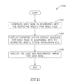
- each processing node 102a and 102n may be operatively configured to execute the boot-up program 117 to first call a corresponding node device build code 119a or 119b to configure the internal hardware components of the processing node 102a or 102n in accordance with a circuit design (not shown in the figures) of a user or developer (step 1102).
- the boot-up program 117 may call an operating system function (such as the "usrAppInit()" function for the VxWorks operating system) to cause the operating system 130 to execute a startup sequence for the respective node 102a or 102n in accordance with a system initialization file (e.g., 1200 in Fig. 12) for the node 102a or 102n.
- a system initialization file e.g., 1200 in Fig. 12
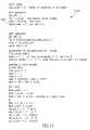
- the system initialization file 1200 identifies one of the applications 118, 120, 122, or 124 for each node to be a master or entry application by specifying an entry point task 1202 for the one application.
- the identified entry point task 1202 for example, may correspond to a task performed by the main thread 148a of the application 118.
- the identified entry point task 1202 calls the load and registration service thread 136 residing on the same node 102a and 102n as the application (e.g., 118) having the entry point task 1202 in order to execute the load and registration thread 136 to initialize the system 100 to implement a network communication infrastructure consistent with the present invention (step 1106).
- Fig. 13 is a flow diagram illustrating a process 1300 performed by the load and registration service thread 136 on at least one of the nodes 102a or 102n to implement the network communication infrastructure for the data processing system 100.
- the load and registration service thread 136 implements the network communication infrastructure in accordance with the architecture configuration file 138 associated with the same node 102a or 102n on which the load and registration service thread 136 resides.
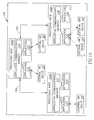
- Fig. 14 depicts an exemplary architecture configuration file 1400 that may be accessed by the load and registration service thread 136.
- the load and registration service thread 136 When performing the process 1300, the load and registration service thread 136 initially identifies each application 118, 120 or 122, 124 to load on the node 102a or 102n where the load and registration service thread 136 resides (step 1302). In one implementation, the load and registration service thread 136 identifies each application to load by identifying an application order list 1402 following a load directive 1404 in the architecture configuration file 138.
- the application order list 1402 may include an application name 1406, 1408, and 1410 for each application 118,120 or 122, 124 to load on the respective node 102a or 102n (the third name 1410 corresponds to a third application not shown for node 102a or 102n in Fig. 1).
- Each application name 1406, 1408, and 1410 corresponds to the application identifier tag 602 provided in the application definition file 160a, 160b, 160c, or 160d for each application 118, 120, 122, or 124.
- the load and registration service thread 136 then loads each identified application into memory 108 (step 1304).
- the load and registration service thread 136 may perform a checksum test in accordance with a size 1412 and checksum value 1414 identified in the architecture configuration file 138 for each application identified in the application order list 1402.
- the load and registration service thread 136 registers each identified application with the routing thread 132 of the node 102a or 102n where the routing thread 132 resides (step 1306).
- the load and registration service thread 136 registers each loaded application by first identifying the application ID 1416 to be assigned or associated with the application names 1406, 1408, 1410.
- the application ID 1416 for each application 118, 120, 122, or 124 is used to identify the application 118, 120, 122, or 124 as the destination or source application of a message 202 (e.g., application ID 212 in the source location 208 or the destination location 210 of a message 202).
- a message 202 e.g., application ID 212 in the source location 208 or the destination location 210 of a message 202).
- each application ID 1416 is assigned to the application names 1406, 1408, 1410 as identified in an application registration list 1418 following a registration directive 1420.
- the application ID 1416 for each application 118, 120, 122, and 124 may be identified in a header file (not shown in the figures) associated with the load and registration service thread 136 such that the load and registration service thread 136 is provided with the application ID 1416 for each application 118, 120, 122, and 124 to be registered at compile time or runtime of the applications 118, 120, 122, or 124.
- the load and registration service thread 136 generates a routing table (e.g., routing table 137a or 137b in Fig.
- Table II Registered Application ID Registered Application Name 4 ZZZ 5 YYY 6 XXX
- the load and registration service thread 136 next identifies a startup command 1422 for each registered application (step 1308) and triggers each registered application to run its respective startup command 1422 (step 1310).
- the load and registration service thread 136 also identifies a run order list 1424 and triggers each registered application to run in accordance with the run order list 1424 (step 1310).
- Fig. 15 is an exemplary functional block diagram of the data processing system 100 illustrating the efficient network communication infrastructure generated upon initialization of the system by the load and registration service thread 136.
- the data processing system 100 is simplified in Fig. 15 to illustrate the network communication infrastructure for communicating a message (e.g., message 1504 in Fig. 15) from a first application 118 to a second application 122 in accordance with the present invention.
- a message e.g., message 1504 in Fig. 15
- the same or equivalent infrastructure may be applied to facilitate communication between each of the applications 118, 120, 122, and 124 on the same node 102a or on distributed nodes 102a and 102n.
- Fig. 15 is an exemplary functional block diagram of the data processing system 100 illustrating the efficient network communication infrastructure generated upon initialization of the system by the load and registration service thread 136.
- the data processing system 100 is simplified in Fig. 15 to illustrate the network communication infrastructure for communicating a message (e.g., message 1504 in Fig. 15
- the network communication infrastructure of the data processing system 100 depicted in Figs. 1, 15 and 16 includes the network 104, each routing thread 132 on each node 102a and 102n, the command thread 156a, 156b, 156c, and 156d associated with each registered application 118, 120, 122, and 124, and the queue 154a, 154b, 154c, and 154f associated with each command thread 156a, 156b, 156c, and 156d.
- the network communication infrastructure of the data processing system 100 may further include each of the plurality of message group handlers 150aa-150af, 150ab-150bg, 150ca-150cg, or 150ca-150cn associated with each application 118, 120, 122, and 124 and accessed by the respective command thread 156a, 156b, 156c, and 156d in accordance with the present invention.
- the main thread 156a or the H/W control thread 148a of the first application 118 may send a request 1502 via the command thread 156a to the routing thread 132 on the same node 102a to cause the routing thread 132 to generate a message 1504 from the global blackboard 134 (e.g. "generate_msg” function in Fig. 16) and to send the message 1504 (e.g., "msg_send” function or "msg_urgent” function in Fig. 16) to the second or destination application 122 in accordance with the request 1502.
- the global blackboard 134 e.g. "generate_msg” function in Fig. 16
- the message 1504 e.g., "msg_send” function or "msg_urgent” function in Fig. 16
- the request 1502 may correspond to a function call (e.g. "generate_msg" function in Fig. 16) that causes the command thread 156a and then routing thread 132 to subsequently awaken and process the request 1502.
- a function call e.g. "generate_msg" function in Fig. 16
- each routing thread 132 on each node 102a or 102n is operatively configured to receive a message 202, 302, 304, 306, 308, or 1504 communicated from a application 122 or 124 distributed across the network 104 on another node 102n or 102a.
- the routing thread 132 of the application 122 receives the message 1504, identifies the application ID 212 in the destination location 210 of the message 1504 and determines whether the application ID 212 is present in the routing table 137b for the node 102n.
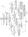
- Fig. 17 is a flow diagram illustrating a process 1700 performed by each routing thread 132 to determine whether a message (e.g., message 202 or 1504) is to be directed to an application 118, 120, 122, or 124 residing on the same node 102a or 102n as the routing thread 132.
- a message e.g., message 202 or 1504
- the routing thread 132 initially determines whether a message 202 or 1504 has been received or is present on the network at the node 102a or 102n where the routing thread 132 resides (step 1702). If a message 202 or 1504 has not been received, the routing thread 132 may wait or enter a sleep state until a message is received. If a message 202 or 1504 has been received, the routing thread 132 then identifies the destination application ID (e.g., the application ID 212 in the destination location 210) in the received message 202 or 1504 (step 1704).
- the destination application ID e.g., the application ID 212 in the destination location 2
- the routing thread 132 determines whether the received message 202 or 1504 has a priority flag 218 set (step 1712). If the received message 202 or 1504 has a priority flag 218 set, the routing thread 132 stores a pointer to the saved message (e.g., pointer 314 to the saved message 302) at the top of the message queue 154a, 154b, 154c, or 154d of the application 118, 120, 122, or 124 (step 1714). The routing thread then raises the event (e.g., event name 619 "EVENT_CI_MSG_AVAILABLE") registered for the command thread 156 associated with the destination application identified in the received message 202 or 1504 (step 1716) before ending processing.
- the event e.g., event name 619 "EVENT_CI_MSG_AVAILABLE
- the routing thread 132 stores a pointer to the saved message (e.g., pointer 314 to the saved message 302) at the end or bottom of the message queue 154a, 154b, 154c, or 154d of the application 118, 120, 122, or 124 (step 1718) before continuing processing at step 1716 to raise the event 619 registered for the command thread 156.
- a pointer to the saved message e.g., pointer 314 to the saved message 302
- the routing thread 132 determines whether the destination application identified in the message 202 or 1504 is running on the node (step 1720). If the destination application identified in the message 202 or 1504 is running on the node, the routing thread 132 continues processing at step 1710. If the destination application identified in the message 202 or 1504 is not running on the node, the routing thread 132 resends the received message 202 or 1504 to the routing thread 132 on a next slave node (e.g., node 102a) (step 1722) before ending processing.
- a next slave node e.g., node 102a
- the routing thread 132 determines whether the node 102a or 102n on which the routing thread 132 resides is in a daisy-chained network of nodes 102a or 102n (step 1724). If the node 102a or 102n on which the routing thread 132 is in a daisy-chained network, the routing thread 132 determines whether the node on which the routing thread 132 resides is the last node in the daisy-chain (step 1726).
- the architecture configuration file 138 may include a daisy-chain identifier (not shown in figures) to indicate that the node 102a or 102n on which the architecture configuration file 138 resides is the last node in the daisy-chain. If the node 102a or 102n on which the routing thread 132 resides is not the last node in the daisy-chain, the routing thread 132 resends the message 202 or 1504 to the next node (e.g., node 102a) in the daisy-chain network (step 1728) before ending processing.
- a daisy-chain identifier not shown in figures
- the routing thread 132 If the node 102a or 102n on which the routing thread 132 resides is not in a daisy-chained network or is the last node in a daisy-chained network, the routing thread 132 then logs an error to reflect that the message 202 or 1504 has an incorrect destination application location 210 (step 1730) and discards the received message 202 or 1504 (step 1732) before ending processing.
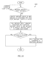
- Fig. 18 is a flow diagram illustrating a process 1800 performed by the command thread 156a, 156b, 156c, or 156d associated with each application 118, 120, 122, or 124 in response to receiving a message available event indication (e.g., event name 619 "EVENT_CI_MSG_AVAlLABLE") registered for the command thread 156.
- a message available event indication e.g., event name 619 "EVENT_CI_MSG_AVAlLABLE” registered for the command thread 156.
- the routing thread 132 raises the message available event 619 associated with the application 118, 120, 122, or 124 after storing a pointer to a received message 202 or 1504 stored in the global blackboard 134.
- Fig. 18 is a flow diagram illustrating a process 1800 performed by the command thread 156a, 156b, 156c, or 156d associated with each application 118, 120, 122, or 124 in response to receiving a message available event indication
- the command thread 156a, 156b, 156c, or 156d initially determines whether a message available event 619 has been received (step 1802). If a message available event 619 has not been received, the command thread 156a, 156b, 156c, or 156d may wait for a message 202 or 1504 by remaining in a sleep state until the message available event 619 is received so that CPU 106 processing associated with the respective command thread 156a, 156b, 156c, or 156d is substantially eliminated.
- the command thread 156a, 156b, 156c, or 156d identifies the message group ID 214 and the message ID 216 associated with the first or top message pointer in the message queue 154a, 154b, 154c, or 154d associated with the command thread 156a, 156b, 156c, or 156d (step 1804).
- the command thread 156a, 156b, 156c, or 156d then calls the message group handler (e.g., 150aa, 150ba, 150ca, or 150da) associated with the identified message group ID 214 and the message ID 216 to process the message 202 or 1504 saved in the global blackboard 134 residing on the same node 102a or 102n as the command thread 156a, 156b, 156c, or 156d (step 1806).
- the command thread 156a, 156b, 156c, or 156d uses the message group ID 214 as an index into the message group table 1000 to identify a pointer to a respective message table 1002 or 1004.
- the command thread 156a, 156b, 156c, or 156d then uses the message ID 216 as an index into the respective message table 1002 or 1004 to identify a pointer to a corresponding one of the message group handlers associated with the message group ID 214 and the message ID 216 of the message 202 or 1504 to be processed.
- the command thread 156a, 156b, 156c, or 156d then may determine whether the received message 202 or 1504 is from a command message group (step 1808). If the received message 202 or 1504 is from a command message group, the command thread 156 may then call a function for generating a response message (step 1810). If the received message 202 or 1504 is not from a command message group or after calling the function for generating a response message, the command thread 156a, 156b, 156c, or 156d ends processing.
- the described implementation includes software, such as the routing thread 132 and the command thread 156a, 156b, 156c, or 156c associated with each application 118, 120, 122, or 124, but the present invention may be implemented as a combination of hardware and software.
- the routing thread 132 and the command thread 156a, 156b, 156c, or 156c may be implemented in the node FPGA build code 119a or 119b for the respective node 102a or 102b.
- the implementation may vary between systems.
- the invention may be implemented with both object-oriented and non-object-oriented programming systems.
- the claims and their equivalents define the scope of the invention.
Landscapes
- Engineering & Computer Science (AREA)
- Software Systems (AREA)
- Theoretical Computer Science (AREA)
- Physics & Mathematics (AREA)
- General Engineering & Computer Science (AREA)
- General Physics & Mathematics (AREA)
- Computer Networks & Wireless Communication (AREA)
- Signal Processing (AREA)
- Multi Processors (AREA)
- Computer And Data Communications (AREA)
- Data Exchanges In Wide-Area Networks (AREA)
Abstract

Description
- The invention was made with U.S. Government support. The U.S. Government has certain rights in this invention. The present invention relates to communication networks, and, more particularly, to systems and methods for implementing an energy efficient network infrastructure for communication between distributed processing nodes.
- A conventional data processing system often includes multiple distributed processing nodes, where each node runs one or more task specific application programs ("task applications"). A conventional processing node typically corresponds to one of multiple processes or processors within a computer system, one of multiple single board computers within a computer system, or one of a multiple computer systems within the conventional data processing system. Task applications running on processing nodes distributed across a conventional network (e.g., computer internal bus, local or wide area network, or Internet) typically communicate with each other using common middleware software, such as Common Object Request Broker Architecture (CORBA) network programming software, that typically requires a significant amount of memory (e.g., 500k-2M bytes or more) and utilizes a significant amount of processor capacity (e.g., 25% or more CPU utilization) and throughput to process message and data communication between the task applications, resulting in substantial power consumption for the respective processing nodes. This problem is of particular concern to data processing nodes that run on batteries or other limited power sources, such as a laptop computer, aircraft avionic computer system, or computer system in a lunar rover or other space vehicle.
- In addition, the network infrastructure in a conventional data processing system typically requires one data processing node to coordinate message communication between other distributed data processing nodes or task applications running on those nodes in accordance with scheduled events, resulting in unnecessary polling of messages for data from a respective task application when the data has not changed. Accordingly, the unnecessary polling of task application messages causes processor power for the respective processing node to be consumed or wasted. For example, one conventional data processing system implemented using a standard network infrastructure that exhibits this problem includes a ground based telemetry station having a central processing node operatively configured to communicate and control communication across a wireless network with a sensor task application running on a remote processing node such as a lunar rover. The sensor task application is typically polled by the central processing node of the ground based telemetry regardless of whether the sensor task application has new data, resulting in unnecessary processor power consumption by the remote processing node.
- Therefore, a need exists for systems and methods that overcome the problems noted above and others previously experienced for implementing a network infrastructure for communication between distributed processing nodes.
- Methods, systems, and articles of manufacture consistent with the present invention provide for a data processing system having an efficient network communication infrastructure.
- In accordance with systems consistent with the present invention, a data processing system is provided having a plurality of data processing nodes distributed across a network. Each data processing node comprises a memory having an application and a routing thread operatively configured to receive a message on the network. The message has an application identifier and a message group identifier. The application has a command thread and a plurality of message group handlers. The routing thread is operatively configured to determine whether the received message is for the application based on the application identifier of the received message and to notify the command thread of the received message in response to determining that the received message is for the application. The command thread is operatively configured to direct the received message to one of the plurality of message group handlers based on the message group identifier of the received message and in response to the notification from the routing thread. Each data processing node further comprises a processor to run the application and the routing thread.
- In accordance with methods consistent with the present invention, a method in a data processing system is provided for providing a network communication infrastructure between a plurality of applications distributed across a plurality of processing nodes connected by a network. The method comprises identifying a list of each of the applications to load in an architecture configuration file associated with a first of the processing nodes and loading each of the applications identified in the list into a memory of the first node. Each of the applications identified in the list has a command thread. The method also comprises assigning a respective application identifier to each of the applications in the list, storing each assigned application identifier in a routing table, and receiving, via the first node, a message on the network. The message has a destination application identifier and a message group identifier. The method further comprises determining whether the destination application identifier corresponds to one of the assigned application identifiers in the routing table, and, when it is determined that the destination application identifier corresponds to one of the assigned application identifiers in the routing table, notifying the command thread of the application corresponding to the destination application identifier that the received message is available for access.
- In accordance with articles of manufacture consistent with the present invention, a computer-readable medium containing instructions for controlling a data processing system to perform a method is provided. The data processing system has a plurality of data processing nodes distributed across a network and a plurality of applications. The method comprises identifying a list of each of the applications to load in an architecture configuration file associated with a first of the processing nodes and loading each of the applications identified in the list into a memory of the first node. Each of the applications identified in the list has a command thread. The method also comprises assigning a respective application identifier to each of the applications in the list, storing each assigned application identifier in a routing table, and receiving, via the first node, a message on the network. The message has a destination application identifier and a message group identifier. The method further comprises determining whether the destination application identifier corresponds to one of the assigned application identifiers in the routing table, and, when it is determined that the destination application identifier corresponds to one of the assigned application identifiers in the routing table, notifying the command thread of the application corresponding to the destination application identifier that the received message is available for access.
- In accordance with systems consistent with the present invention, a data processing system is provided having a plurality of data processing nodes distributed across a network and a plurality of applications. Each data processing node comprises: a memory; a secondary storage having an architecture configuration file; means for identifying in the architecture configuration file a list of each of the applications to load in the memory of the respective node; and means for loading each of the applications identified in the list into the memory of the respective node. Each of the applications identified in the list has a command thread. Each data processing node also comprises: means for assigning a respective application identifier to each of the applications in the list; means for storing each assigned application identifier in a routing table; and means for receiving a message on the network. The message has a destination application identifier and a message group identifier. Each data processing node further comprises means for determining whether the destination application identifier corresponds to one of the assigned application identifiers in the routing table; and means for, when it is determined that the destination application identifier corresponds to one of the assigned application identifiers in the routing table, notifying the command thread of the application corresponding to the destination application identifier that the received message is available for access.
- Other systems, methods, features, and advantages of the present invention will be or will become apparent to one with skill in the art upon examination of the following figures and detailed description. It is intended that all such additional systems, methods, features, and advantages be included within this description, be within the scope of the invention, and be protected by the accompanying claims.
- The accompanying drawings, which are incorporated in and constitute a part of this specification, illustrate an implementation of the present invention and, together with the description, serve to explain the advantages and principles of the invention. In the drawings:
- Fig. 1A is a block diagram of an exemplary data processing system having a plurality of data processing nodes distributed across a network; each data processing node having one or more applications and application communications manager operatively configured to provide an energy efficient network infrastructure for communication between the applications on the distributed processing nodes in accordance with the present invention;
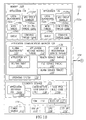
- Fig. 1B is a detailed block diagram of the data processing system in Fig. 1A;
- Fig. 2 depicts the structure of an exemplary message transmitted by a first application to a second application via a first routing thread of the application communications manager residing on the same node as the first application and a second routing thread of the application communication manager residing on the same node as the second application;
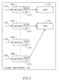
- Fig. 3 depicts the structure of an exemplary global blackboard storage for each application communications manager on each processing node;
- Fig. 4 depicts the structure of an exemplary local blackboard storage for each application on each processing node;
- Fig. 5 depicts the structure of an exemplary application API implemented by each application on each processing node to force each application to be in compliance with the communications infrastructure provided by the application communication managers in accordance with the present invention;
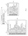
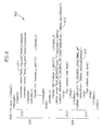
- Fig. 6 depicts the structure of an exemplary application definition file used to generate the source code for one or more of the applications in accordance with the present invention;
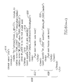
- Fig. 7 depicts a section of the application definition file that defines an association between a message and a message group in accordance with the present invention;
- Fig. 8 is a functional block diagram of an exemplary development computer system suitable for generating each application based on the definition file associated with the application in accordance with the present invention;
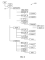
- Fig. 9 depicts one embodiment of a makefile structure for compiling and linking the source code for each application in accordance with the present invention;
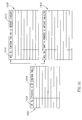
- Fig. 10 depicts the structure of a message group table and a plurality of message tables associated with the message group table collectively used by each application for processing a received message;
- Fig. 11 is a flow diagram illustrating steps in a method for initializing the data processing system to generate an efficient network communication infrastructure consistent with the present invention;
- Fig. 12 depicts an exemplary system initialization file executed by each processing node's operating system in accordance with the method for initializing the data processing system;
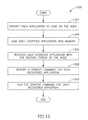
- Fig. 13 is a flow diagram illustrating a process performed by a load and registration service thread on at least one of the processing nodes in accordance with the method for initializing the data processing system;
- Fig. 14 depicts an exemplary architecture configuration file accessed by the load and registration service thread to load, register, and initiate execution of the one or more applications in accordance with the present invention;
- Fig. 15 is an exemplary functional block diagram of the data processing system in Fig. 1 illustrating the efficient network communication infrastructure generated upon initialization of the system;
- Fig. 16 is an exemplary sequence diagram illustrating a process for communicating a message from a first application to a second application via a first routing thread of the application communications manager residing on the same node as the first application and a second routing thread of the application communication manager residing on the same node as the second application;
- Fig. 17 is a flow diagram illustrating a process performed by each routing thread to determine whether a message is to be directed to an application residing on the same node as the routing thread; and
- Fig. 18 is a flow diagram illustrating a process performed by each command thread in response to receiving a message available event indication from the routing thread residing on the same node as the command thread.
- Reference will now be made in detail to an implementation in accordance with methods, systems, and products consistent with the present invention as illustrated in the accompanying drawings. The same reference numbers may be used throughout the drawings and the following description to refer to the same or like parts.
- Fig. 1A depicts an exemplary block diagram of a
data processing system 100 configured to have an energy efficient network infrastructure consistent with the present invention. Fig. 1B is a detailed block diagram of thedata processing system 100. Thedata processing system 100 has a plurality ofdata processing nodes network 104. As shown in Fig. 1A, thedata processing nodes data processing nodes - In one implementation, each
data processing node data processing node network 104 may be any known serial bus (e.g., UART serial bus), multiplex bus, local bus (e.g., Industry Standard Architecture (ISA) bus, Micro Channel Architecture (MCA) bus or Enhanced ISA (EISA) bus), or private or public communication network, such as a local area network ("LAN"), WAN, Peer-to-Peer, or the Internet. Thenetwork 104 may include hardwired, as well as wireless branches. In one implementation, thenetwork 104 may be a logical bus operatively configured in memory, such asmemory 108 onprocessing node 102a. - As shown in Figure 1B, each
data processing node applications CPU 106 at a time while a multi-threaded program may have several threads running through different code paths that may be separately and substantially simultaneously executed by the CPU such that the time required to switch threads and the state needed to be saved and restored when changing threads is minimized. - Each
data processing node memory 108, asecondary storage device 110 an input/output (I/O)unit 112, and apower source 113, such as a battery, each of which is operatively connected to theCPU 106 via a local bus orbackplane 114. The secondary storage may be a non-volatile RAM, a fixed or removable hard disk, a read/write CD, or any other non-volatile memory device. The I/O unit 112 may comprise discrete external hardware components (e.g., D/A converters, address/data transceivers, receiver, transmitter, modem, bus/network drivers, or other I/O components) for interfacing with external systems or devices 50-58 in Fig. 1A, such as a thermal or radiation sensor, an antenna, actuator, altimeter, keyboard,display 115, or other device that may be controlled by an application running on the respectivedata processing node - Each
data processing node only memory 116 for storing a boot-upprogram 117 accessed by therespective CPU 106 upon power-up in order to load and initialize an energy efficient network infrastructure for thedata processing system 100 in accordance with the present invention. In one implementation in which theprocessing node program 117 may initially call a nodedevice build code 119a or 119b to configure the internal hardware components of theprocessing node -
Memory 108 in eachdata processing node more applications application communications manager operating system 130. Theoperating system 130 may be VxWorks™, LynxOS®, Solaris™ or other operating system having a plurality of programmable events or interrupts that allow process control to be transferred to a corresponding event handler associated with a thread (e.g.,command thread 156a-156d in Fig. 1B of one of theapplications application communications manager application main thread respective command thread main thread command thread - In general, each of the
applications data processing system 100 may correspond to an aircraft avionic data processing system, such as the space shuttle, having a sensor subsystem (e.g., a radar, thermal sensor, or cabin pressure sensor) and a central computer subsystem. In this example, theprocessing node 102a may be a single board computer in the sensor subsystem and theprocessing node 102n may be another single board computer in the central computer subsystem. Each of theapplications command thread application communications manager main thread main thread 148a of theapplication 118 in theprocessing node 102a (e.g., the sensor subsystem) may be developed to control a radar sensor to sense for airborne targets upon command from theapplication 122 located across thenetwork 104 in thedata processing node 102n (e.g., the central computer subsystem). In this example, themain thread 148a of theapplication 118 may first provide (via thecommand thread 156a and the applications communications manager 126) raw sensed target data to the other application 120 (via thecommand thread 156b) in thesame node 102a for target detection processing. Themain thread 148b of theother application 120 may then submit the processed target detection data across the network in one or more messages to the requesting application 122 (via thecommand thread 156c and the applications communications manager 128). In accordance with infrastructure provided by theapplication communication managers main thread 148a and thecommand thread 156a of theapplication 118 may not be required to operate (e.g., both enter a sleep state) until triggered to "wake up" and respond to the command (e.g., to sense for airborne targets) sent from theapplication 122. As discussed below, in accordance with the present invention, eachapplication communication manager data processing node 102a and 102 is operatively configured to facilitate communication between the applications such that the power consumption of therespective processing node applications - As shown in Fig. 1B, each
application communications manager application same node respective routing thread 132. Rather than assign eachnode application routing thread 132 is able to determine whether a message transmitted on thenetwork 104 is directed to anapplication respective routing thread 132. For example, Fig. 2 depicts the exemplary structure of amessage 202 that may be transmitted by a first application (e.g., 118) to a second application (e.g., 122) via therouting threads 132 residing on thesame nodes second applications message 202 includes amessage header 204 and amessage body 206. Themessage header 204 includes asource location 208 and adestination location 210. Thesource location 208 includes an application identifier ("ID") 212 assigned to thefirst application 118 that transmitted themessage 202. The source location also includes amessage group ID 214 and a function ormessage ID 216. Themessage group ID 214 identifies themessage 202 as being associated with one of a plurality of functional group types, such as a command message group, a data message group, a control message group, or an application event message group. Themessage group ID 214 allows sorting ofmessages 202 transmitted betweenapplications applications applications message ID 216 identifies the function or message handler that corresponds to themessage 202. Thedestination location 210 also has anapplication ID 212, amessage group ID 214, and amessage ID 216. Therouting thread 132 associated with eachprocessing node message 202 on thenetwork 104 and to determine whether themessage 202 is to be directed to anapplication same node respective routing thread 132. Thus, therouting threads 132 on eachnode network 104 without a central application ornode managing network 104 traffic via message polling or broadcasting a message based on an event raised by the one of theapplications network 104 is reduced and unnecessary message construction/deconstruction associated with a message polling implementation is avoided, saving power consumption for thenodes - As shown in Fig. 2, the
message body 206 may include a group offlags 218 one of which identifies themessage 202 as a priority message so that therouting thread 132 on thesame node destination application 210 causes the identifieddestination application 210 to handle themessage 202 before any other message identified in the application'squeue - The
message body 206 may also include aresponse code 220 that is set when themessage 202 is sent to the identifieddestination application 210 in response to aprevious message 202 sent to the identifiedsource application 208. - The
message body 206 may also includedata 222 associated with themessage 202 that the identifieddestination application 208 needs or is being commanded to use based on the function ormessage ID 216. - Returning to Fig. 1B, each
application communications manager global blackboard 134 storage that is operatively controlled by therouting thread 132 of therespective manager routing thread 132 stores in theglobal blackboard 134 eachmessage application same processing node routing thread 132 as described in further detail below. As mentioned above, eachmessage destination ID 210, which is used to route themessage destination application message group ID 214 and themessage ID 216 identified in thedestination ID 210. In one implementation, eachglobal blackboard 134 may have themessages messages messages global blackboard 134 may also have a separate structure or space for each message (e.g., 302) related to the health of anapplication health service thread 140 as discussed below. Eachglobal blackboard 134 may also have a separate structure or space for each message (e.g., 306) related to an alarm from anapplication alarm service thread 144 as discussed below so that alarm data may be assembled by the global blackboard into a single area for common notification or broadcast to eachapplication global blackboard 134 is operatively configured or defined such that the global data state or condition of each thread (e.g.,main thread 148a,command thread 156a, and H/W control thread 158a) in each application residing on the same node as the global blackboard 134 (e.g., application 118) so that a local blackboard (e.g., 152a) associated with a respective application (e.g., 118) is able to monitor a transition in a state or condition of data associated with a respective thread (e.g., H/W control thread 158a). - When
data message respective routing thread 132, therouting thread 132 stores thedata message global blackboard 134 is operatively configured using object oriented programming or other known common data storage techniques such thatdata 312 associated with two ormore messages global blackboard 134. When therespective routing thread 132 receives amessage application routing thread 132 stores apointer respective message message queue application command thread command thread message - Each
application local blackboard message data respective application global blackboard 134. Fig. 4 depicts the structure of an exemplarylocal blackboard 402 storage for eachapplication processing node local blackboard saveable portion 404 and anunsaveable portion 406. Thesaveable portion 404 has dynamic data 408 (e.g., state ofmessage data 310 and 312) that may change during runtime of theapplication respective blackboard saveable portion 404 corresponds to or includes the global state of data associated with the respective application's threads (e.g., H/W control thread 158a of application 118) maintained in the global blackboard. Theunsaveable portion 406 hasstatic data 410 that is set when the associatedapplication application saveable portion 404 of thelocal blackboard global blackboard 134, data storage capacity is saved and data movement between theapplications CPU 106 processing, allowing thenodes - Returning to Fig. 1B, each
application communications manager registration service thread 136 that is operatively configured to load eachapplication secondary storage 110 intomemory 108, define the order eachapplication system 100, and initiate execution of theapplications architecture configuration file 138 as discussed in detail below. In one implementation, the load andregistration thread 136 is initially called by the boot-upprogram 117. - Each
application communication manager health service thread 140, afile service thread 142, and analarm service thread 144. Thehealth service thread 140 is asystem 100 function that may be called by one application (e.g., 118) on onenode 102a to identify the health of another application (e.g., 122) on anothernode 102n in thedata processing system 100. Thehealth service thread 140 will return an alive status or heartbeat identifier if the other application (e.g., 122) is loaded inmemory 108 and running. - The
file service thread 142 comprises a plurality of file operations shown in Table I below that anapplication memory 108 orsecondary storage 110. Each file operation is defined to replacecorresponding operating system 130 functions in order to enforce source code and compiled code commonality betweenapplications CPU 106 cycles associated with file access and manipulation.Table I 1. file open 2. file close 3. file write 4. file read 5. file verify 6. file delete 7. file rename 8. file copy 9. file append 10. file delta - The
alarm service thread 144 comprises asystem 100 function that may be called by one application (e.g., 118) to signal an alarm event to another application (e.g., 122) over thenetwork 104 without having to go through a central application to broadcast the alarm event. - Each
application communication manager application API 146 that is incorporated into or instantiated in eachapplication application communication managers application API 146 instantiated in eachapplication application API 146 includes a messagehandler type definition 502, alocal blackboard 504, a message input queue ("MsgInputQueue")type definition 506, and a command thread 508 ("Receive Command Thread()") function. The messagehandler type definition 502 provides anapplication application communication manager respective application message routing thread 132 stores a pointer to each message received by the applicationmessage routing thread 132 for the respective application. In one implementation, the message input queue is defined to be a FIFO type buffer. Each applicationmessage routing thread 132 is operatively configured to signal that a message pointer has been stored in aqueue 506 associated with anapplication application command thread 508 function identifies the structure for receiving and responding to an associated message available event from the applicationmessage routing thread 132. - The
application API 146 also includes a send message function 516 that may be used by thecommand thread 508 to process a message for output to the applicationmessage routing thread 132 and a receivemessage function 518 to process a message identified by a pointer stored in thequeue 506. - The
application API 146 may also include a hardware control thread 520 function that includes a hardwareoutput control function 522 for controlling discrete external hardware components of the I/O unit 112 associated with therespective application O unit 112 associated with therespective application input buffer type 526. - As shown in Fig. 1B, in addition to a
main thread application local blackboard queue command thread Application API 146 of theapplication communication manager specific application - If the
application O unit 112, theapplication W control thread Application API 146. - In one implementation, each
application application definition file application definition file 600 that used to generate the source code for acorresponding application application definition file application identifier tag 602, amessage definition section 604, amain thread definition 606, and acommand thread definition 608. A developer may include other thread definitions, such as the H/W control thread command thread definition 608. Theapplication identifier tag 602 corresponds to a name or other identifier given to theapplication message definition section 604 identifies the messages to be supported (e.g., transmitted or received) by therespective application message definition section 604 includes a requiredmessage subsection 610 that identifies messages associated with one or more of theservice threads application application command message 611 as shown in Fig. 6 which may be invoked by thehealth service thread 140 to identify the health (e.g., "alive") of the application (e.g., 118) on a periodic basis or in response to a request from anothernode 102n in thedata processing system 100. - As previously discussed, each message (e.g.,
message 202 in Fig. 2) transmitted betweenapplications message 202 for processing by the destination application identified in themessage 202. Fig. 7 depicts amessage group section 702 of theapplication definition file 600 that defines an association between a message and a message group in accordance with the present invention. As shown in Fig. 7, themessage group section 702 includes a messagegroup identifier tag 703 and one or moremessage definition subsections group identifier tag 602 corresponds to a name (e.g., "ctl_mem" may reflect a control group) or other identifier given to the message group by the application developer. Eachmessage definition subsection tag 602. In one implementation, eachmessage definition subsection function name 708 or other identifier, anargument identifier 710 and associatedargument type 712, and amessage body 714. As discussed below, eachmessage group section 702 is used to generate a message group table 808 in Fig. 8 that may be accessed by each of theapplications message 202 in accordance with the present invention. It is contemplated that eachmessage message group 702 once in one application definition file (e.g., 160a) or in a separate message definition file (not shown in figures). The message group table 808, when built in accordance with the present invention, then allows each application to identify the message group handler for processing a receivedmessage 202. - Returning to Fig. 6, each
main thread definition 606 includes one or morecallback definitions function thread services operating system 130 and that may be invoked by the associated main thread (e.g., 148a, 148b, 148c, or 148d) during runtime. Eachcallback function - Each
command thread definition 608 includes athread identifier tag 616 set to a name (e.g., "cmd") or other identifier to signal that thethread definition 608 is for acommand thread command thread definition 608 to define other threads. In this instance, thethread identifier tag 616 may be set to another name ("e.g., H/W") to identify the other thread (e.g., the H/W control thread 158a). Eachcommand thread definition 608 also includes anevent ID tag 618 that is set to the event name 619 (e.g., "EVENT_CI_MSG_AVAILABLE") to be registered with therouting thread 132 and binded to acorresponding operating system 130 event such that therouting thread 132 may raise thecorresponding operating system 130 event to cause thecommand thread 156a of therespective application message 202 in accordance with the present invention. Thecommand thread definition 608 also includes an event function orhandler identifier 620 andevent handler code 622 to be associated with theevent name 619. The identifiedevent handler 620 corresponds to one of the message group handlers (e.g., 150aa, 150ba, 150ca, or 150da) defined for therespective application command thread - Fig. 8 is a functional block diagram of an exemplary
development computer system 800 suitable for generating eachapplication application definition file development computer system 800 may be a standard personal computer (such as Dell or Apple computer) or workstation (such as a Sun Microsystems SPARC workstation). Thedevelopment computer system 800 includes a definition-to-source code translator 802 operatively configured to parse eachapplication definition file corresponding source code 804a-804d for each definedapplication source code 804a-804d may be C++ or other object oriented source code. The definition-to-source code translator 802 may be an XML parser/XSLT (extensible Stylesheet Language Translator) processor program (such as "cygwin"™" available at www.cygwin.com) that uses one or more Stylesheets operatively configured to translateapplication definition files application API 146 of theapplications communication manager development computer system 800 also includes a compiler/linker 806 compiling and linking thesource code 804a-d for theapplications makefile 807. Fig. 9 depicts one embodiment of amakefile structure 900 suitable for use by the compiler/linker 806 to generate eachapplication message routing thread 132,health service thread 140,file service thread 142,alarm service thread 144, message group table 808 and message tables 810a-810n for eachnode data processing system 100. Accordingly, the process depicted in Fig. 8 of generating theapplications application definition files 160a-160d ensures eachapplication application communication managers data processing system 100. - In an alternative implementation, the message group table 808 and the message tables 810a-810n may be built during compile time by or runtime by the load and
registration service thread 136 from each message group definition (e.g.,section 702 ofapplication definitions - Fig. 10 depicts the structure of an exemplary message group table 1000 and an exemplary plurality of message tables 1002 and 1004 associated with the message group table 1000 generated from the
message group definition 702. The message group table 1000 stores eachmessage group ID 1006 in association with apointer 1008 to one of the message tables 1002 and 1004 associated with themessage group ID 1006. Each message table 1002 and 1004 stores eachmessage ID 1010 in association with apointer 1012 to one of the message group handlers 150aa-af, 150ba-bg, 150ca-150cg, or 150da-150dn defined for processing a message, such asmessage 202 in Fig. 2, in accordance with the present invention. In one implementation, when amessage 202 is received by the routing thread thecommand thread application message group ID 214 andmessage ID 216 stored in theheader 204 of themessage 202 as indexes into the message group table 1000 and the respective message table 1002 or 1004. - Although the
routing thread 132, service threads 136-144,command threads 156a-156d, and H/W control threads 158a-158d and other programs/threads are described as being implemented as software, the present invention may be implemented as a combination of hardware and software. In addition, although aspects of one implementation shown in Figs. 1A-1B are depicted as being stored in memory, one skilled in the art will appreciate that all or part of systems and methods consistent with the present invention may be stored on or read from other computer-readable media, such as secondary storage devices, like hard disks, floppy disks, and CD-ROM; a carrier wave received from a network such as the Internet; or other forms of ROM or RAM either currently known or later developed. Further, although specific components ofdata processing system 100 have been described, a data processing system suitable for use with methods, systems, and articles of manufacture consistent with the present invention may contain additional or different components. - Turning to Fig. 11, a flow diagram is shown that illustrates steps in a
method 1100 for initializing thedata processing system 100 to generate an efficient network communication infrastructure consistent with the present invention. In one implementation in which one or more of thenodes processing node program 117 to first call a corresponding nodedevice build code 119a or 119b to configure the internal hardware components of theprocessing node program 117 may call an operating system function (such as the "usrAppInit()" function for the VxWorks operating system) to cause theoperating system 130 to execute a startup sequence for therespective node node system initialization file 1200 identifies one of theapplications entry point task 1202 for the one application. The identifiedentry point task 1202, for example, may correspond to a task performed by themain thread 148a of theapplication 118. The identifiedentry point task 1202 calls the load andregistration service thread 136 residing on thesame node entry point task 1202 in order to execute the load andregistration thread 136 to initialize thesystem 100 to implement a network communication infrastructure consistent with the present invention (step 1106). - Fig. 13 is a flow diagram illustrating a
process 1300 performed by the load andregistration service thread 136 on at least one of thenodes data processing system 100. In one implementation, the load andregistration service thread 136 implements the network communication infrastructure in accordance with thearchitecture configuration file 138 associated with thesame node registration service thread 136 resides. Fig. 14 depicts an exemplaryarchitecture configuration file 1400 that may be accessed by the load andregistration service thread 136. When performing theprocess 1300, the load andregistration service thread 136 initially identifies eachapplication node registration service thread 136 resides (step 1302). In one implementation, the load andregistration service thread 136 identifies each application to load by identifying anapplication order list 1402 following aload directive 1404 in thearchitecture configuration file 138. In the example shown in Fig. 14, theapplication order list 1402 may include anapplication name respective node third name 1410 corresponds to a third application not shown fornode application name application identifier tag 602 provided in theapplication definition file application - The load and
registration service thread 136 then loads each identified application into memory 108 (step 1304). As part of the load step, the load andregistration service thread 136 may perform a checksum test in accordance with asize 1412 andchecksum value 1414 identified in thearchitecture configuration file 138 for each application identified in theapplication order list 1402. - Next, the load and
registration service thread 136 registers each identified application with therouting thread 132 of thenode routing thread 132 resides (step 1306). In one implementation, the load andregistration service thread 136 registers each loaded application by first identifying theapplication ID 1416 to be assigned or associated with theapplication names application ID 1416 for eachapplication application application ID 212 in thesource location 208 or thedestination location 210 of a message 202). In the implementation shown in Fig. 14, eachapplication ID 1416 is assigned to theapplication names application registration list 1418 following aregistration directive 1420. In an alternative example, theapplication ID 1416 for eachapplication registration service thread 136 such that the load andregistration service thread 136 is provided with theapplication ID 1416 for eachapplication applications registration service thread 136 generates a routing table (e.g., routing table 137a or 137b in Fig. 1B) as shown in Table II that lists theapplication ID 1416 of each registered application 118,120 or 122,124. The routing table 137a or 137b may also store theapplication name respective application ID 1416.Table II Registered Application ID Registered Application Name 4 ZZZ 5 YYY 6 XXX - Each
routing thread 132 is operatively configured to access therouting thread same node respective routing thread 132. In accordance with the present invention, eachrouting thread 132 accesses therespective routing thread destination location 210 in Fig. 2) identified in amessage 202 received on thenetwork 104 resides on thesame node routing thread 132. - Returning to Fig. 13, the load and
registration service thread 136 next identifies astartup command 1422 for each registered application (step 1308) and triggers each registered application to run its respective startup command 1422 (step 1310). In one implementation, the load andregistration service thread 136 also identifies arun order list 1424 and triggers each registered application to run in accordance with the run order list 1424 (step 1310). - Fig. 15 is an exemplary functional block diagram of the
data processing system 100 illustrating the efficient network communication infrastructure generated upon initialization of the system by the load andregistration service thread 136. For clarity in the discussion, thedata processing system 100 is simplified in Fig. 15 to illustrate the network communication infrastructure for communicating a message (e.g.,message 1504 in Fig. 15) from afirst application 118 to asecond application 122 in accordance with the present invention. However, one having skill in the art would appreciate that the same or equivalent infrastructure may be applied to facilitate communication between each of theapplications same node 102a or on distributednodes process 1600 for communicating a message (e.g.,message 1504 in Fig. 15) from thefirst application 118 to thesecond application 122 utilizing the network communication infrastructure depicted in Fig. 15. In one implementation, the network communication infrastructure of thedata processing system 100 depicted in Figs. 1, 15 and 16 includes thenetwork 104, eachrouting thread 132 on eachnode command thread registered application queue command thread data processing system 100 may further include each of the plurality of message group handlers 150aa-150af, 150ab-150bg, 150ca-150cg, or 150ca-150cn associated with eachapplication respective command thread - As shown in Figs. 15 and 16, the
main thread 156a or the H/W control thread 148a of thefirst application 118 may send arequest 1502 via thecommand thread 156a to therouting thread 132 on thesame node 102a to cause therouting thread 132 to generate amessage 1504 from the global blackboard 134 (e.g. "generate_msg" function in Fig. 16) and to send the message 1504 (e.g., "msg_send" function or "msg_urgent" function in Fig. 16) to the second ordestination application 122 in accordance with therequest 1502. In one implementation in which thecommand thread 156a and/or therouting thread 132 are in a sleep state awaiting a call or event in accordance with the present invention, therequest 1502 may correspond to a function call (e.g. "generate_msg" function in Fig. 16) that causes thecommand thread 156a and then routingthread 132 to subsequently awaken and process therequest 1502. - As previously discussed, each
routing thread 132 on eachnode message application network 104 on anothernode routing thread 132 of theapplication 122 receives themessage 1504, identifies theapplication ID 212 in thedestination location 210 of themessage 1504 and determines whether theapplication ID 212 is present in the routing table 137b for thenode 102n. If theapplication ID 212 is in the routing table 137b, therouting thread 132 is operatively configured to storedata 1506 associated with themessage 1504 in the global blackboard, place a pointer (e.g., pointer 314) to themessage 1504 and associateddata 1506 in themessage queue 154c of theapplication 122, and notify thecommand thread 156c that a message is available or has been received for theapplication 122 as further described below. Fig. 17 is a flow diagram illustrating aprocess 1700 performed by eachrouting thread 132 to determine whether a message (e.g.,message 202 or 1504) is to be directed to anapplication same node routing thread 132. As shown in Fig. 17, therouting thread 132 initially determines whether amessage node routing thread 132 resides (step 1702). If amessage routing thread 132 may wait or enter a sleep state until a message is received. If amessage routing thread 132 then identifies the destination application ID (e.g., theapplication ID 212 in the destination location 210) in the receivedmessage 202 or 1504 (step 1704). - Next, the
routing thread 132 determines whether the destination application ID is in the routing table 137a or 137b associated with the routing thread 132 (step 1706). If the destination application ID is in the routing table 137a or 137b, therouting thread 132 determines whether thenode routing thread 132 resides is a master node in a star configured network (step 1708). If thenode routing thread 132 resides is not a master node in a star configured network, therouting thread 132 saves themessage global backboard 134 associated with the routing thread (step 1710). Therouting thread 132 then determines whether the receivedmessage priority flag 218 set (step 1712). If the receivedmessage priority flag 218 set, therouting thread 132 stores a pointer to the saved message (e.g.,pointer 314 to the saved message 302) at the top of themessage queue application event name 619 "EVENT_CI_MSG_AVAILABLE") registered for thecommand thread 156 associated with the destination application identified in the receivedmessage 202 or 1504 (step 1716) before ending processing. - If the received
message priority flag 218 set, therouting thread 132 stores a pointer to the saved message (e.g.,pointer 314 to the saved message 302) at the end or bottom of themessage queue application step 1716 to raise theevent 619 registered for thecommand thread 156. - If the
node routing thread 132 resides is a master node in a star configured network, therouting thread 132 then determines whether the destination application identified in themessage message routing thread 132 continues processing atstep 1710. If the destination application identified in themessage routing thread 132 resends the receivedmessage routing thread 132 on a next slave node (e.g.,node 102a) (step 1722) before ending processing. - If the destination application ID is not in the routing table 137a or 137b, the
routing thread 132 determines whether thenode routing thread 132 resides is in a daisy-chained network ofnodes node routing thread 132 is in a daisy-chained network, therouting thread 132 determines whether the node on which therouting thread 132 resides is the last node in the daisy-chain (step 1726). In one implementation, thearchitecture configuration file 138 may include a daisy-chain identifier (not shown in figures) to indicate that thenode architecture configuration file 138 resides is the last node in the daisy-chain. If thenode routing thread 132 resides is not the last node in the daisy-chain, therouting thread 132 resends themessage node 102a) in the daisy-chain network (step 1728) before ending processing. If thenode routing thread 132 resides is not in a daisy-chained network or is the last node in a daisy-chained network, therouting thread 132 then logs an error to reflect that themessage message 202 or 1504 (step 1732) before ending processing. - Fig. 18 is a flow diagram illustrating a
process 1800 performed by thecommand thread application event name 619 "EVENT_CI_MSG_AVAlLABLE") registered for thecommand thread 156. As discussed above, therouting thread 132 raises the messageavailable event 619 associated with theapplication message global blackboard 134. As shown in Fig. 18, thecommand thread available event 619 has been received (step 1802). If a messageavailable event 619 has not been received, thecommand thread message available event 619 is received so thatCPU 106 processing associated with therespective command thread available event 619 has been received, thecommand thread message group ID 214 and themessage ID 216 associated with the first or top message pointer in themessage queue command thread command thread message group ID 214 and themessage ID 216 to process themessage global blackboard 134 residing on thesame node command thread command thread message group ID 214 as an index into the message group table 1000 to identify a pointer to a respective message table 1002 or 1004. Thecommand thread message ID 216 as an index into the respective message table 1002 or 1004 to identify a pointer to a corresponding one of the message group handlers associated with themessage group ID 214 and themessage ID 216 of themessage command thread message message command thread 156 may then call a function for generating a response message (step 1810). If the receivedmessage command thread - While various embodiments of the present invention have been described, it will be apparent to those of skill in the art that many more embodiments and implementations are possible that are within the scope of this invention. Accordingly, the present invention is not to be restricted except in light of the attached claims and their equivalents.
- The foregoing description of implementations of the invention has been presented for purposes of illustration and description. It is not exhaustive and does not limit the invention to the precise form disclosed. Modifications and variations are possible in light of the above teachings or may be acquired from practicing of the invention. Additionally, the described implementation includes software, such as the
routing thread 132 and thecommand thread application routing thread 132 and thecommand thread FPGA build code 119a or 119b for therespective node
Claims (21)
- A data processing system having a plurality of data processing nodes distributed across a network, each data processing node comprising:a memory having an application and a routing thread operatively configured to receive a message on the network, the message having an application identifier and a message group identifier, the application having a command thread and a plurality of message group handlers, the routing thread being further operatively configured to determine whether the received message is for the application based on the application identifier of the received message and to notify the command thread of the received message in response to determining that the received message is for the application, the command thread being operatively configured to direct the received message to one of the plurality of message group handlers based on the message group identifier of the received message and in response to the notification from the routing thread; anda processor to run the application and the routing thread.
- A data processing system according to claim 1, wherein the application has a message queue associated with the command thread and, in response to determining that the received message is for the application, the routing thread is operatively configured to store the received message and to store a pointer to the stored message in the message queue.
- A data processing system according to claim 1 or 2, wherein the command thread is associated with one of a plurality of operating system events and the routing thread notifies the command thread of the received message by raising the one event.
- A data processing system according to claim 1, 2 or 3, wherein the message further includes a message identifier and, in response to the notification from the routing thread, the command thread directs the received message to one of the plurality of message group handlers based on the message group identifier and the message identifier.
- A data processing system according to any of claims 1-4, each data processing node further comprises a secondary storage having an architecture configuration file, wherein the application identifier is one of a plurality of application identifiers provided in the architecture configuration file, and the memory of each data processing node further includes a load and registration thread that is operatively configured to load each application in memory having a corresponding application identifier among the plurality of application identifiers in the architecture configuration file.
- A data processing system according to claim 5, wherein the load and registration thread is further operatively configured to generate a routing table that includes the corresponding application identifier for each application loaded in memory of the data processing node where the load and registration thread resides.
- A data processing system according to claim 6, wherein the routing thread for each data processing node determines that the received message is for the application in response to determining that the application identifier of the received message is in the routing table.
- A method in a data processing system for providing a network communication infrastructure between a plurality of applications distributed across a plurality of processing nodes connected by a network, the method comprising:identifying a list of each of the applications to load in an architecture configuration file associated with a first of the processing nodes;loading each of the applications identified in the list into a memory of the first node, each of the applications identified in the list having a command thread;assigning a respective application identifier to each of the applications in the list;storing each assigned application identifier in a routing table;receiving, via the first node, a message on the network, the message having a destination application identifier and a message group identifier;determining whether the destination application identifier corresponds to one of the assigned application identifiers in the routing table; andwhen it is determined that the destination application identifier corresponds to one of the assigned application identifiers in the routing table, notifying the command thread of the application corresponding to the destination application identifier that the received message is available for access.
- A method in a data processing system according to claim 8, wherein the command thread of the application corresponding to the destination application identifier is operatively configured to direct, in response to the notification, the received message to one of a plurality of message group handlers based on the message group identifier of the received message.
- A method in a data processing system according to claim 8 or 9, wherein each of the applications in the list has a message queue associated with the command thread of the respective application and, when it is determined that the destination application identifier corresponds to one of the assigned application identifiers in the routing table, the method further comprises storing the received message, and providing a pointer to the stored message in the message queue of the application corresponding to the destination application identifier.
- A method in a data processing system according to claim 8, 9 or 10, wherein the command thread of the application corresponding to the destination application identifier is associated with a first of a plurality of operating system events, and the step of notifying comprises raising the first event.
- A method in a data processing system according to any of claims 8-11, wherein the message further includes a message identifier and, in response to the notification, the command thread of the application corresponding to the destination application identifier directs the received message to one of the plurality of message group handlers based on the message group identifier and the message identifier.
- A computer-readable medium containing instructions for controlling a data processing system to perform a method, the data processing system having a plurality of data processing nodes distributed across a network and a plurality of applications, the method comprising the steps of:identifying a list of each of the applications to load in an architecture configuration file associated with a first of the processing nodes;loading each of the applications identified in the list into a memory of the first node, each of the applications identified in the list having a command thread;assigning a respective application identifier to each of the applications in the list;storing each assigned application identifier in a routing table;receiving, via the first node, a message on the network, the message having a destination application identifier and a message group identifier;determining whether the destination application identifier corresponds to one of the assigned application identifiers in the routing table; andwhen it is determined that the destination application identifier corresponds to one of the assigned application identifiers in the routing table, notifying the command thread of the application corresponding to the destination application identifier that the received message is available for access.
- A computer-readable medium according to claim 13, wherein the command thread of the application corresponding to the destination application identifier is operatively configured to direct, in response to the notification, the received message to one of a plurality of message group handlers based on the message group identifier of the received message.
- A computer-readable medium according to claim 13 or 14, wherein each of the applications in the list has a message queue associated with the command thread of the respective application and, when it is determined that the destination application identifier corresponds to one of the assigned application identifiers in the routing table, the method further comprises storing the received message, and providing a pointer to the stored message in the message queue of the application corresponding to the destination application identifier.
- A computer-readable medium according to claim 13, 14 or 15, wherein the command thread of the application corresponding to the destination application identifier is associated with a first of a plurality of operating system events, and the step of notifying comprises raising the first event.
- A computer-readable medium according to any of claims 13-16, wherein the message further includes a message identifier and, in response to the notification from the routing thread, the command thread of the application corresponding to the destination application identifier directs the received message to one of the plurality of message group handlers based on the message group identifier and the message identifier.
- A data processing system having a plurality of data processing nodes distributed across a network and a plurality of applications, each data processing node comprising:a memory;a secondary storage having an architecture configuration file;means for identifying in the architecture configuration file a list of each of the applications to load in the memory of the respective node;means for loading each of the applications identified in the list into the memory of the respective node, each of the applications identified in the list having a command thread;means for assigning a respective application identifier to each of the applications in the list;means for storing each assigned application identifier in a routing table;means for receiving a message on the network, the message having a destination application identifier and a message group identifier;means for determining whether the destination application identifier corresponds to one of the assigned application identifiers in the routing table; andmeans for, when it is determined that the destination application identifier corresponds to one of the assigned application identifiers in the routing table, notifying the command thread of the application corresponding to the destination application identifier that the received message is available for access.
- A data processing system according to claim 18, wherein the command thread of the application corresponding to the destination application identifier is operatively configured to direct, in response to the notification, the received message to one of a plurality of message group handlers based on the message group identifier of the received message.
- A data processing system according to claim 18 or 19, wherein each of the applications in the list has a message queue associated with the command thread of the respective application and further comprising means for when it is determined that the destination application identifier corresponds to one of the assigned application identifiers in the routing table, storing the received message, and providing a pointer to the stored message in the message queue of the application corresponding to the destination application identifier.
- A data processing system according to claim 18, 19 or 20, wherein the command thread of the application corresponding to the destination application identifier is associated with a first of a plurality of operating system events, and the means for notifying the command thread comprises means for raising the first event.
Applications Claiming Priority (1)
| Application Number | Priority Date | Filing Date | Title |
|---|---|---|---|
| US11/288,804 US8671133B2 (en) | 2005-11-29 | 2005-11-29 | System having an energy efficient network infrastructure for communication between distributed processing nodes |
Publications (2)
| Publication Number | Publication Date |
|---|---|
| EP1791058A1 true EP1791058A1 (en) | 2007-05-30 |
| EP1791058B1 EP1791058B1 (en) | 2010-02-24 |
Family
ID=37607264
Family Applications (1)
| Application Number | Title | Priority Date | Filing Date |
|---|---|---|---|
| EP06077069A Active EP1791058B1 (en) | 2005-11-29 | 2006-11-21 | A system having an energy efficient network infrastructure for communication between distributed processing nodes |
Country Status (4)
| Country | Link |
|---|---|
| US (1) | US8671133B2 (en) |
| EP (1) | EP1791058B1 (en) |
| AT (1) | ATE459046T1 (en) |
| DE (1) | DE602006012426D1 (en) |
Cited By (5)
| Publication number | Priority date | Publication date | Assignee | Title |
|---|---|---|---|---|
| CN102193821A (en) * | 2010-03-11 | 2011-09-21 | 福特全球技术公司 | Method for queuing messages for transmission to/from a vehicle |
| US8718632B2 (en) | 2010-08-26 | 2014-05-06 | Ford Global Technologies, Llc | Service delivery network |
| US9172639B2 (en) | 2011-12-06 | 2015-10-27 | International Business Machines Corporation | Distributing functions in a distributed and embedded environment |
| US9305288B2 (en) | 2008-12-30 | 2016-04-05 | Ford Global Technologies, Llc | System and method for provisioning electronic mail in a vehicle |
| CN105510892A (en) * | 2015-12-25 | 2016-04-20 | 西安电子工程研究所 | VxWorks real-time control computer-based radar debugging system |
Families Citing this family (18)
| Publication number | Priority date | Publication date | Assignee | Title |
|---|---|---|---|---|
| US8069208B2 (en) * | 2006-04-21 | 2011-11-29 | Microsoft Corporation | Peer-to-peer buddy request and response |
| US20080181254A1 (en) * | 2007-01-25 | 2008-07-31 | Inventec Corporation | Data transmission method |
| JP5038813B2 (en) * | 2007-08-07 | 2012-10-03 | 株式会社東芝 | Wireless sensor device and wireless sensor device activation control method |
| US20090307712A1 (en) * | 2008-06-09 | 2009-12-10 | Rex Young | Actor virtual machine |
| US11036565B2 (en) | 2008-06-09 | 2021-06-15 | Rex Young | Service virtual machine |
| EP2798792B8 (en) * | 2011-12-29 | 2022-02-16 | British Telecommunications public limited company | Distributed system management |
| US9817739B1 (en) * | 2012-10-31 | 2017-11-14 | Veritas Technologies Llc | Method to restore a virtual environment based on a state of applications/tiers |
| US10089224B2 (en) | 2013-03-15 | 2018-10-02 | The Boeing Company | Write caching using volatile shadow memory |
| US9811455B2 (en) | 2013-03-15 | 2017-11-07 | The Boeing Company | Accessing different types of memory by respective distinct command with different timing requirements |
| US9904556B1 (en) | 2013-03-15 | 2018-02-27 | The Boeing Company | Executing a boot sequence including movement of data through a buffer memory |
| RU183418U1 (en) * | 2018-05-30 | 2018-09-21 | Федеральное государственное казённое военное образовательное учреждение высшего образования "Военная академия воздушно-космической обороны имени Маршала Советского Союза Г.К. Жукова" Министерства обороны Российской Федерации | Aircraft computer with configurable processors |
| US11822681B1 (en) * | 2018-12-31 | 2023-11-21 | United Services Automobile Association (Usaa) | Data processing system with virtual machine grouping based on commonalities between virtual machines |
| US11182226B1 (en) * | 2018-12-31 | 2021-11-23 | United Services Automobile Association (Usaa) | Data processing system with application grouping based on inter-application communication |
| US11347534B1 (en) | 2018-12-31 | 2022-05-31 | United Services Automobile Association (Usaa) | Data processing system with consolidation of virtual machines and host server standby and power up functionality |
| US11243098B2 (en) | 2019-02-08 | 2022-02-08 | Simmonds Precision Products, Inc. | Configurable nodes for sensing systems |
| US10938643B2 (en) | 2019-02-08 | 2021-03-02 | Simmonds Precision Products, Inc. | Distributed sensing systems and nodes therefor |
| CN109885526B (en) * | 2019-03-29 | 2023-08-22 | 中国电子科技集团公司第三十八研究所 | Information processing platform based on OpenVPX bus |
| US12124890B2 (en) * | 2022-07-26 | 2024-10-22 | Sap Se | Event provisioning for high-level programing language platform |
Citations (3)
| Publication number | Priority date | Publication date | Assignee | Title |
|---|---|---|---|---|
| US20030093499A1 (en) * | 2001-10-05 | 2003-05-15 | Adam Messinger | System for application server messaging with multiple dispatch pools |
| WO2004025466A2 (en) * | 2002-09-16 | 2004-03-25 | Clearcube Technology, Inc. | Distributed computing infrastructure |
| US20040156346A1 (en) * | 2002-11-14 | 2004-08-12 | O'neill Alan | Methods and apparatus for extending mobile IP |
-
2005
- 2005-11-29 US US11/288,804 patent/US8671133B2/en active Active
-
2006
- 2006-11-21 EP EP06077069A patent/EP1791058B1/en active Active
- 2006-11-21 DE DE602006012426T patent/DE602006012426D1/en active Active
- 2006-11-21 AT AT06077069T patent/ATE459046T1/en not_active IP Right Cessation
Patent Citations (3)
| Publication number | Priority date | Publication date | Assignee | Title |
|---|---|---|---|---|
| US20030093499A1 (en) * | 2001-10-05 | 2003-05-15 | Adam Messinger | System for application server messaging with multiple dispatch pools |
| WO2004025466A2 (en) * | 2002-09-16 | 2004-03-25 | Clearcube Technology, Inc. | Distributed computing infrastructure |
| US20040156346A1 (en) * | 2002-11-14 | 2004-08-12 | O'neill Alan | Methods and apparatus for extending mobile IP |
Non-Patent Citations (3)
| Title |
|---|
| BHASKAR KRISHNAMACHARI, DEBORAH ESTRIN, STEPHEN WICKER: "Modelling Data-Centric Routing in Wireless Sensor Networks", IEEE INFOCOM, 5 April 2004 (2004-04-05), pages 1 - 11, XP002416057, Retrieved from the Internet <URL:http://web.archive.org/web/20040405160802/http://www2.parc.com/spl/members/zhao/stanford-cs428/readings/Networking/Krishnamachari_infocom02.pdf> [retrieved on 20070123] * |
| DURRESI A ET AL: "Delay-Energy Aware Routing Protocol for Sensor and Actor Networks", PARALLEL AND DISTRIBUTED SYSTEMS, 2005. PROCEEDINGS. 11TH INTERNATIONAL CONFERENCE ON FUKUOKA, JAPAN 20-22 JULY 2005, PISCATAWAY, NJ, USA,IEEE, 20 July 2005 (2005-07-20), pages 292 - 298, XP010852138, ISBN: 0-7695-2281-5 * |
| ZHENG R ET AL: "On-demand power management for ad hoc networks", AD HOC NETWORKS, ELSEVIER, vol. 3, no. 1, 26 November 2003 (2003-11-26), pages 51 - 68, XP004645830, ISSN: 1570-8705 * |
Cited By (8)
| Publication number | Priority date | Publication date | Assignee | Title |
|---|---|---|---|---|
| US9305288B2 (en) | 2008-12-30 | 2016-04-05 | Ford Global Technologies, Llc | System and method for provisioning electronic mail in a vehicle |
| CN102193821A (en) * | 2010-03-11 | 2011-09-21 | 福特全球技术公司 | Method for queuing messages for transmission to/from a vehicle |
| EP2372546A1 (en) * | 2010-03-11 | 2011-10-05 | Ford Global Technologies, LLC | Method and systems for queuing messages for vehicle-related services |
| US8718632B2 (en) | 2010-08-26 | 2014-05-06 | Ford Global Technologies, Llc | Service delivery network |
| US9172639B2 (en) | 2011-12-06 | 2015-10-27 | International Business Machines Corporation | Distributing functions in a distributed and embedded environment |
| US9178808B2 (en) | 2011-12-06 | 2015-11-03 | International Business Machines Corporation | Distributing functions in a distributed and embedded environment |
| CN105510892A (en) * | 2015-12-25 | 2016-04-20 | 西安电子工程研究所 | VxWorks real-time control computer-based radar debugging system |
| CN105510892B (en) * | 2015-12-25 | 2017-10-03 | 西安电子工程研究所 | Radar debugging system based on VxWorks real-time control computer |
Also Published As
| Publication number | Publication date |
|---|---|
| ATE459046T1 (en) | 2010-03-15 |
| DE602006012426D1 (en) | 2010-04-08 |
| US8671133B2 (en) | 2014-03-11 |
| US20070121631A1 (en) | 2007-05-31 |
| EP1791058B1 (en) | 2010-02-24 |
Similar Documents
| Publication | Publication Date | Title |
|---|---|---|
| EP1791058B1 (en) | A system having an energy efficient network infrastructure for communication between distributed processing nodes | |
| CN100570565C (en) | Operating system service method and system based on strategy are provided in supervisory routine | |
| US10620988B2 (en) | Distributed computing architecture | |
| US6986148B2 (en) | Methods and systems for providing platform-independent shared software components for mobile devices | |
| US8141104B2 (en) | Integrating non-compliant providers of dynamic services into a resource management infrastructure | |
| US20020046230A1 (en) | Method for scheduling thread execution on a limited number of operating system threads | |
| US20050216670A1 (en) | Method and system for caching presentation data | |
| US20030233634A1 (en) | Open debugging environment | |
| US7974987B1 (en) | Database for storing device handle data in an extensible firmware interface environment | |
| JP2004536382A (en) | Systems, methods, and articles of manufacture using replaceable components to select network communication channel components with replaceable quality of service features | |
| EP2743830A1 (en) | Flexible data communication among partitions in integrated modular avionics | |
| JP2005056404A (en) | Method and apparatus for providing updated system locality during run time | |
| US7076551B2 (en) | Using remote procedure calls to manage co-processor resources | |
| EP3633507B1 (en) | Technologies for secure and efficient native code invocation for firmware services | |
| US20080148355A1 (en) | Providing Policy-Based Operating System Services in an Operating System on a Computing System | |
| EP1684179A1 (en) | Information processing device, memory area management method, and computer program | |
| JP4084956B2 (en) | Object collection method and system | |
| US7171550B1 (en) | Data structure and method for managing modules associated with a kernel | |
| EP1265148B1 (en) | Using software interrupts to manage communication between data processors | |
| US8078637B1 (en) | Memory efficient peim-to-peim interface database | |
| US20230048915A1 (en) | Low latency remoting to accelerators | |
| US20240127034A1 (en) | Apparatus and method for distributed processing of neural network | |
| Bagchi | Nano-kernel: a dynamically reconfigurable kernel for WSN | |
| Rincón et al. | Supporting Operating Systems for Reconfigurable Computing: A Distributed Service Oriented Approach. | |
| CN121704954A (en) | Method for realizing real-time container engine |
Legal Events
| Date | Code | Title | Description |
|---|---|---|---|
| PUAI | Public reference made under article 153(3) epc to a published international application that has entered the european phase |
Free format text: ORIGINAL CODE: 0009012 |
|
| AK | Designated contracting states |
Kind code of ref document: A1 Designated state(s): AT BE BG CH CY CZ DE DK EE ES FI FR GB GR HU IE IS IT LI LT LU LV MC NL PL PT RO SE SI SK TR |
|
| AX | Request for extension of the european patent |
Extension state: AL BA HR MK YU |
|
| 17P | Request for examination filed |
Effective date: 20071130 |
|
| 17Q | First examination report despatched |
Effective date: 20080108 |
|
| AKX | Designation fees paid |
Designated state(s): AT BE BG CH CY CZ DE DK EE ES FI FR GB GR HU IE IS IT LI LT LU LV MC NL PL PT RO SE SI SK TR |
|
| GRAP | Despatch of communication of intention to grant a patent |
Free format text: ORIGINAL CODE: EPIDOSNIGR1 |
|
| GRAS | Grant fee paid |
Free format text: ORIGINAL CODE: EPIDOSNIGR3 |
|
| GRAA | (expected) grant |
Free format text: ORIGINAL CODE: 0009210 |
|
| AK | Designated contracting states |
Kind code of ref document: B1 Designated state(s): AT BE BG CH CY CZ DE DK EE ES FI FR GB GR HU IE IS IT LI LT LU LV MC NL PL PT RO SE SI SK TR |
|
| REG | Reference to a national code |
Ref country code: GB Ref legal event code: FG4D |
|
| REG | Reference to a national code |
Ref country code: CH Ref legal event code: EP |
|
| REG | Reference to a national code |
Ref country code: IE Ref legal event code: FG4D |
|
| REF | Corresponds to: |
Ref document number: 602006012426 Country of ref document: DE Date of ref document: 20100408 Kind code of ref document: P |
|
| REG | Reference to a national code |
Ref country code: DE Ref legal event code: R096 Ref document number: 602006012426 Country of ref document: DE Effective date: 20100408 |
|
| REG | Reference to a national code |
Ref country code: NL Ref legal event code: VDEP Effective date: 20100224 |
|
| LTIE | Lt: invalidation of european patent or patent extension |
Effective date: 20100224 |
|
| PG25 | Lapsed in a contracting state [announced via postgrant information from national office to epo] |
Ref country code: PT Free format text: LAPSE BECAUSE OF FAILURE TO SUBMIT A TRANSLATION OF THE DESCRIPTION OR TO PAY THE FEE WITHIN THE PRESCRIBED TIME-LIMIT Effective date: 20100625 Ref country code: LT Free format text: LAPSE BECAUSE OF FAILURE TO SUBMIT A TRANSLATION OF THE DESCRIPTION OR TO PAY THE FEE WITHIN THE PRESCRIBED TIME-LIMIT Effective date: 20100224 Ref country code: IS Free format text: LAPSE BECAUSE OF FAILURE TO SUBMIT A TRANSLATION OF THE DESCRIPTION OR TO PAY THE FEE WITHIN THE PRESCRIBED TIME-LIMIT Effective date: 20100624 |
|
| PG25 | Lapsed in a contracting state [announced via postgrant information from national office to epo] |
Ref country code: SI Free format text: LAPSE BECAUSE OF FAILURE TO SUBMIT A TRANSLATION OF THE DESCRIPTION OR TO PAY THE FEE WITHIN THE PRESCRIBED TIME-LIMIT Effective date: 20100224 Ref country code: FI Free format text: LAPSE BECAUSE OF FAILURE TO SUBMIT A TRANSLATION OF THE DESCRIPTION OR TO PAY THE FEE WITHIN THE PRESCRIBED TIME-LIMIT Effective date: 20100224 Ref country code: LV Free format text: LAPSE BECAUSE OF FAILURE TO SUBMIT A TRANSLATION OF THE DESCRIPTION OR TO PAY THE FEE WITHIN THE PRESCRIBED TIME-LIMIT Effective date: 20100224 Ref country code: PL Free format text: LAPSE BECAUSE OF FAILURE TO SUBMIT A TRANSLATION OF THE DESCRIPTION OR TO PAY THE FEE WITHIN THE PRESCRIBED TIME-LIMIT Effective date: 20100224 Ref country code: AT Free format text: LAPSE BECAUSE OF FAILURE TO SUBMIT A TRANSLATION OF THE DESCRIPTION OR TO PAY THE FEE WITHIN THE PRESCRIBED TIME-LIMIT Effective date: 20100224 |
|
| PG25 | Lapsed in a contracting state [announced via postgrant information from national office to epo] |
Ref country code: NL Free format text: LAPSE BECAUSE OF FAILURE TO SUBMIT A TRANSLATION OF THE DESCRIPTION OR TO PAY THE FEE WITHIN THE PRESCRIBED TIME-LIMIT Effective date: 20100224 Ref country code: GR Free format text: LAPSE BECAUSE OF FAILURE TO SUBMIT A TRANSLATION OF THE DESCRIPTION OR TO PAY THE FEE WITHIN THE PRESCRIBED TIME-LIMIT Effective date: 20100525 Ref country code: BE Free format text: LAPSE BECAUSE OF FAILURE TO SUBMIT A TRANSLATION OF THE DESCRIPTION OR TO PAY THE FEE WITHIN THE PRESCRIBED TIME-LIMIT Effective date: 20100224 Ref country code: CY Free format text: LAPSE BECAUSE OF FAILURE TO SUBMIT A TRANSLATION OF THE DESCRIPTION OR TO PAY THE FEE WITHIN THE PRESCRIBED TIME-LIMIT Effective date: 20100224 Ref country code: EE Free format text: LAPSE BECAUSE OF FAILURE TO SUBMIT A TRANSLATION OF THE DESCRIPTION OR TO PAY THE FEE WITHIN THE PRESCRIBED TIME-LIMIT Effective date: 20100224 Ref country code: ES Free format text: LAPSE BECAUSE OF FAILURE TO SUBMIT A TRANSLATION OF THE DESCRIPTION OR TO PAY THE FEE WITHIN THE PRESCRIBED TIME-LIMIT Effective date: 20100604 Ref country code: RO Free format text: LAPSE BECAUSE OF FAILURE TO SUBMIT A TRANSLATION OF THE DESCRIPTION OR TO PAY THE FEE WITHIN THE PRESCRIBED TIME-LIMIT Effective date: 20100224 Ref country code: SE Free format text: LAPSE BECAUSE OF FAILURE TO SUBMIT A TRANSLATION OF THE DESCRIPTION OR TO PAY THE FEE WITHIN THE PRESCRIBED TIME-LIMIT Effective date: 20100224 |
|
| PG25 | Lapsed in a contracting state [announced via postgrant information from national office to epo] |
Ref country code: SK Free format text: LAPSE BECAUSE OF FAILURE TO SUBMIT A TRANSLATION OF THE DESCRIPTION OR TO PAY THE FEE WITHIN THE PRESCRIBED TIME-LIMIT Effective date: 20100224 Ref country code: BG Free format text: LAPSE BECAUSE OF FAILURE TO SUBMIT A TRANSLATION OF THE DESCRIPTION OR TO PAY THE FEE WITHIN THE PRESCRIBED TIME-LIMIT Effective date: 20100524 Ref country code: CZ Free format text: LAPSE BECAUSE OF FAILURE TO SUBMIT A TRANSLATION OF THE DESCRIPTION OR TO PAY THE FEE WITHIN THE PRESCRIBED TIME-LIMIT Effective date: 20100224 |
|
| PLBE | No opposition filed within time limit |
Free format text: ORIGINAL CODE: 0009261 |
|
| STAA | Information on the status of an ep patent application or granted ep patent |
Free format text: STATUS: NO OPPOSITION FILED WITHIN TIME LIMIT |
|
| PG25 | Lapsed in a contracting state [announced via postgrant information from national office to epo] |
Ref country code: DK Free format text: LAPSE BECAUSE OF FAILURE TO SUBMIT A TRANSLATION OF THE DESCRIPTION OR TO PAY THE FEE WITHIN THE PRESCRIBED TIME-LIMIT Effective date: 20100224 |
|
| 26N | No opposition filed |
Effective date: 20101125 |
|
| REG | Reference to a national code |
Ref country code: DE Ref legal event code: R097 Ref document number: 602006012426 Country of ref document: DE Effective date: 20101125 |
|
| PG25 | Lapsed in a contracting state [announced via postgrant information from national office to epo] |
Ref country code: MC Free format text: LAPSE BECAUSE OF NON-PAYMENT OF DUE FEES Effective date: 20101130 |
|
| REG | Reference to a national code |
Ref country code: CH Ref legal event code: PL |
|
| PG25 | Lapsed in a contracting state [announced via postgrant information from national office to epo] |
Ref country code: LI Free format text: LAPSE BECAUSE OF NON-PAYMENT OF DUE FEES Effective date: 20101130 Ref country code: CH Free format text: LAPSE BECAUSE OF NON-PAYMENT OF DUE FEES Effective date: 20101130 |
|
| PG25 | Lapsed in a contracting state [announced via postgrant information from national office to epo] |
Ref country code: IE Free format text: LAPSE BECAUSE OF NON-PAYMENT OF DUE FEES Effective date: 20101121 |
|
| PG25 | Lapsed in a contracting state [announced via postgrant information from national office to epo] |
Ref country code: HU Free format text: LAPSE BECAUSE OF FAILURE TO SUBMIT A TRANSLATION OF THE DESCRIPTION OR TO PAY THE FEE WITHIN THE PRESCRIBED TIME-LIMIT Effective date: 20100825 Ref country code: LU Free format text: LAPSE BECAUSE OF NON-PAYMENT OF DUE FEES Effective date: 20101121 |
|
| PG25 | Lapsed in a contracting state [announced via postgrant information from national office to epo] |
Ref country code: TR Free format text: LAPSE BECAUSE OF FAILURE TO SUBMIT A TRANSLATION OF THE DESCRIPTION OR TO PAY THE FEE WITHIN THE PRESCRIBED TIME-LIMIT Effective date: 20100224 |
|
| REG | Reference to a national code |
Ref country code: FR Ref legal event code: PLFP Year of fee payment: 10 |
|
| REG | Reference to a national code |
Ref country code: FR Ref legal event code: PLFP Year of fee payment: 11 |
|
| REG | Reference to a national code |
Ref country code: FR Ref legal event code: PLFP Year of fee payment: 12 |
|
| P01 | Opt-out of the competence of the unified patent court (upc) registered |
Effective date: 20230516 |
|
| PGFP | Annual fee paid to national office [announced via postgrant information from national office to epo] |
Ref country code: DE Payment date: 20251128 Year of fee payment: 20 |
|
| PGFP | Annual fee paid to national office [announced via postgrant information from national office to epo] |
Ref country code: GB Payment date: 20251127 Year of fee payment: 20 |
|
| PGFP | Annual fee paid to national office [announced via postgrant information from national office to epo] |
Ref country code: IT Payment date: 20251119 Year of fee payment: 20 |
|
| PGFP | Annual fee paid to national office [announced via postgrant information from national office to epo] |
Ref country code: FR Payment date: 20251125 Year of fee payment: 20 |