EP1790951A1 - Signal processing circuit for encoder - Google Patents
Signal processing circuit for encoder Download PDFInfo
- Publication number
- EP1790951A1 EP1790951A1 EP06024622A EP06024622A EP1790951A1 EP 1790951 A1 EP1790951 A1 EP 1790951A1 EP 06024622 A EP06024622 A EP 06024622A EP 06024622 A EP06024622 A EP 06024622A EP 1790951 A1 EP1790951 A1 EP 1790951A1
- Authority
- EP
- European Patent Office
- Prior art keywords
- detectors
- difference
- angular
- calculating
- angular values
- Prior art date
- Legal status (The legal status is an assumption and is not a legal conclusion. Google has not performed a legal analysis and makes no representation as to the accuracy of the status listed.)
- Granted
Links
- 238000000034 method Methods 0.000 abstract description 3
- 238000010586 diagram Methods 0.000 description 6
- 238000012935 Averaging Methods 0.000 description 4
- 238000006073 displacement reaction Methods 0.000 description 2
- 230000002159 abnormal effect Effects 0.000 description 1
- 238000001514 detection method Methods 0.000 description 1
- 230000000977 initiatory effect Effects 0.000 description 1
Images
Classifications
-
- G—PHYSICS
- G01—MEASURING; TESTING
- G01D—MEASURING NOT SPECIALLY ADAPTED FOR A SPECIFIC VARIABLE; ARRANGEMENTS FOR MEASURING TWO OR MORE VARIABLES NOT COVERED IN A SINGLE OTHER SUBCLASS; TARIFF METERING APPARATUS; MEASURING OR TESTING NOT OTHERWISE PROVIDED FOR
- G01D5/00—Mechanical means for transferring the output of a sensing member; Means for converting the output of a sensing member to another variable where the form or nature of the sensing member does not constrain the means for converting; Transducers not specially adapted for a specific variable
- G01D5/12—Mechanical means for transferring the output of a sensing member; Means for converting the output of a sensing member to another variable where the form or nature of the sensing member does not constrain the means for converting; Transducers not specially adapted for a specific variable using electric or magnetic means
- G01D5/244—Mechanical means for transferring the output of a sensing member; Means for converting the output of a sensing member to another variable where the form or nature of the sensing member does not constrain the means for converting; Transducers not specially adapted for a specific variable using electric or magnetic means influencing characteristics of pulses or pulse trains; generating pulses or pulse trains
- G01D5/24457—Failure detection
- G01D5/24461—Failure detection by redundancy or plausibility
-
- G—PHYSICS
- G01—MEASURING; TESTING
- G01D—MEASURING NOT SPECIALLY ADAPTED FOR A SPECIFIC VARIABLE; ARRANGEMENTS FOR MEASURING TWO OR MORE VARIABLES NOT COVERED IN A SINGLE OTHER SUBCLASS; TARIFF METERING APPARATUS; MEASURING OR TESTING NOT OTHERWISE PROVIDED FOR
- G01D18/00—Testing or calibrating apparatus or arrangements provided for in groups G01D1/00 - G01D15/00
- G01D18/001—Calibrating encoders
-
- G—PHYSICS
- G01—MEASURING; TESTING
- G01D—MEASURING NOT SPECIALLY ADAPTED FOR A SPECIFIC VARIABLE; ARRANGEMENTS FOR MEASURING TWO OR MORE VARIABLES NOT COVERED IN A SINGLE OTHER SUBCLASS; TARIFF METERING APPARATUS; MEASURING OR TESTING NOT OTHERWISE PROVIDED FOR
- G01D5/00—Mechanical means for transferring the output of a sensing member; Means for converting the output of a sensing member to another variable where the form or nature of the sensing member does not constrain the means for converting; Transducers not specially adapted for a specific variable
- G01D5/12—Mechanical means for transferring the output of a sensing member; Means for converting the output of a sensing member to another variable where the form or nature of the sensing member does not constrain the means for converting; Transducers not specially adapted for a specific variable using electric or magnetic means
- G01D5/244—Mechanical means for transferring the output of a sensing member; Means for converting the output of a sensing member to another variable where the form or nature of the sensing member does not constrain the means for converting; Transducers not specially adapted for a specific variable using electric or magnetic means influencing characteristics of pulses or pulse trains; generating pulses or pulse trains
- G01D5/24471—Error correction
- G01D5/2449—Error correction using hard-stored calibration data
Definitions
- the present invention relates to a signal processing circuit for an encoder of a type having two detectors arranged on both sides of a rotating shaft in order to eliminate an eccentricity error.
- One of the detection errors that can occur in an encoder is an eccentricity error, i.e., the error caused by the eccentricity of its rotating part.
- This eccentricity error can be canceled by arranging two detectors on both sides of the rotating shaft and by taking an average between the angular values ⁇ 1 and ⁇ 2 calculated from their respective output signals, as described, for example, in the prior art section of JP 3195117B .
- the difference between ⁇ 1 and ⁇ 2 calculated from the output signals of the respective detectors may become equal to 180°, depending on the mounting condition of the detectors; in that case, two solutions ⁇ ' and ⁇ " can occur, resulting in a 180° displacement, as shown in Figure 3.
- an encoder signal processing circuit for calculating position data by processing signals output from first and second detectors arranged on both sides of a rotating shaft, comprising: angular value calculating means for calculating first and second angular values respectively from the output signals of the first and second detectors; initial difference storing means for storing an initial value of an angular difference calculated between the first and second angular values; correcting means for correcting one or the other of the first and second angular values by the initial value of the angular difference stored in the initial difference storing means; and position data calculating means for calculating the position data by taking an average between the two angular values after the correction is made by the correcting means.
- the two angular values after the correction become close to each other; as a result, if the detectors are mounted in any positional relationship, the situation where the difference between the two values becomes equal to 180°, causing two solutions to occur, can be prevented, and thus the mounting of the detectors can be facilitated.
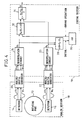
- Figure 4 is a block diagram showing the configuration of an encoder signal processing circuit according to a first embodiment of the present invention.
- an analog section 10 As a rotating part 12 rotates, two sine wave signals A 1 and B 1 , 90° apart in phase, are output from a detector 14 mounted near the rotating part 12. Similarly, sine wave signals A 2 and B 2 are output from a detector 16 mounted opposite the detector 14 across the rotating part 12.
- An interpolation circuit 24 calculates an angular value ⁇ 1 from the digital values A 1D and B 1D by a known method, and outputs the result.
- an interpolation circuit 26 calculates an angular value ⁇ 2 from the digital values A 2D and B 2D , and outputs the result.
Landscapes
- Physics & Mathematics (AREA)
- General Physics & Mathematics (AREA)
- Transmission And Conversion Of Sensor Element Output (AREA)
Abstract
Description
- The present invention relates to a signal processing circuit for an encoder of a type having two detectors arranged on both sides of a rotating shaft in order to eliminate an eccentricity error.
- One of the detection errors that can occur in an encoder is an eccentricity error, i.e., the error caused by the eccentricity of its rotating part. This eccentricity error can be canceled by arranging two detectors on both sides of the rotating shaft and by taking an average between the angular values θ1 and θ2 calculated from their respective output signals, as described, for example, in the prior art section of
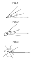
JP 3195117B - As the average θ = (θ1 + θ2) /2 is the average of angular values, it is not the mere average of the values, but the value of θ is chosen so that, after the averaging, the angle θ is located between θ1 and θ2, as shown in Figures 1 and 2.
- However, in a certain type of encoder, such as a magnetic encoder, in which the detectors are mounted to the stator or rotor after the encoder is assembled, the difference between θ1 and θ2 calculated from the output signals of the respective detectors may become equal to 180°, depending on the mounting condition of the detectors; in that case, two solutions θ' and θ" can occur, resulting in a 180° displacement, as shown in Figure 3.
- Therefore, to avoid the above situation, in the prior art the detectors have had to be mounted by exercising care so that the difference between θ1 and θ2 will not become equal to 180° while considering the positional relationship between the detectors, and hence the problem that it takes time to mount the detectors appears.
- It is accordingly an object of the present invention to provide a signal processing circuit that facilitates the mounting of the detectors in an encoder of the type in which two detectors are arranged on both sides of the rotating shaft in order to eliminate an eccentricity error.
- According to the present invention, there is provided an encoder signal processing circuit, for calculating position data by processing signals output from first and second detectors arranged on both sides of a rotating shaft, comprising: angular value calculating means for calculating first and second angular values respectively from the output signals of the first and second detectors; initial difference storing means for storing an initial value of an angular difference calculated between the first and second angular values; correcting means for correcting one or the other of the first and second angular values by the initial value of the angular difference stored in the initial difference storing means; and position data calculating means for calculating the position data by taking an average between the two angular values after the correction is made by the correcting means.
- When one or the other of the first and second angular values is corrected by the initial value of their difference, if the angular value before the correction contains an error associated with the positional relationship between the detectors, the two angular values after the correction become close to each other; as a result, if the detectors are mounted in any positional relationship, the situation where the difference between the two values becomes equal to 180°, causing two solutions to occur, can be prevented, and thus the mounting of the detectors can be facilitated.
-
- Figure 1 is a diagram for explaining the averaging of angular values;
- Figure 2 is a diagram for explaining the averaging of angular values;
- Figure 3 is a diagram for explaining the problem of averaging that can occur when the angular difference is 180°;
- Figure 4 is a block diagram showing a first embodiment of the present invention; and
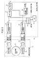
- Figure 5 is a block diagram showing a first embodiment of the present invention.
- Figure 4 is a block diagram showing the configuration of an encoder signal processing circuit according to a first embodiment of the present invention.
- In an
analog section 10, as a rotatingpart 12 rotates, two sine wave signals A1 and B1, 90° apart in phase, are output from adetector 14 mounted near therotating part 12. Similarly, sine wave signals A2 and B2 are output from adetector 16 mounted opposite thedetector 14 across therotating part 12. Analog/digital converters analog section 10 with adigital section 18, convert the analog values A1, B1, A2, and B2 into digital values A1D, B1D, A2D, and B2D, respectively. Aninterpolation circuit 24 calculates an angular value θ1 from the digital values A1D and B1D by a known method, and outputs the result. Similarly, aninterpolation circuit 26 calculates an angular value θ2 from the digital values A2D and B2D, and outputs the result. - A △
θ calculator 28 calculates △θ = θ2 - θ1 (or θ1 - θ2), and stores the value of △θ in amemory 30 after mounting thedetectors corrector 32 applies a correction by adding the value of △θ stored in thememory 30 to the value of θ1 (or θ2), i.e., by the calculation of θ3 = θ1 + △θ. - A
position data calculator 34 calculates the average between the corrected value θ3 and the value of θ2, i.e., θ = (θ3 + θ2) /2, and outputs the result as the position data θ. - In this way, by applying a correction by adding the initial difference △θ to the angular value θ1, the initial phase difference associated with the positional relationship between the
detectors detectors - Figure 5 shows a second embodiment according to the present invention. In this embodiment, an
alarm processor 36 is added to the configuration of Figure 4. Thealarm processor 36 outputs an alarm when 180° - θALM < θ3 - θ2 < 180° + θALM, that is, when the angular difference (θ3 - θ2) after the correction lies within the range of 180° to θALM, where θALM is a predetermined value. - In this way, an alarm can be issued whenever there arises the possibility of an abnormal value being output as the phase difference after the correction becomes close to 180° due, for example, to the breakage or a displacement in the mounting position of the detectors.
Claims (2)
- An encoder signal processing circuit for calculating position data by processing signals output from first and second detectors arranged on both sides of a rotating shaft, comprising:angular value calculating means for calculating first and second angular values respectively from the output signals of the first and second detectors;initial difference storing means for storing an initial value of an angular difference calculated between the first and second angular values;correcting means for correcting one of the first and second angular values by the initial value of the angular difference stored in the initial difference storing means; andposition data calculating means for calculating the position data by taking an average between the two angular values after the correction is made by the correcting means.
- An encoder signal processing circuit according to claim 1, further comprising alarm outputting means for outputting an alarm when the difference between the two angular values, after the correction is made by the correcting means, lies within a prescribed range.
Applications Claiming Priority (1)
| Application Number | Priority Date | Filing Date | Title |
|---|---|---|---|
| JP2005343478A JP4005096B2 (en) | 2005-11-29 | 2005-11-29 | Encoder signal processing circuit |
Publications (2)
| Publication Number | Publication Date |
|---|---|
| EP1790951A1 true EP1790951A1 (en) | 2007-05-30 |
| EP1790951B1 EP1790951B1 (en) | 2014-11-26 |
Family
ID=37794725
Family Applications (1)
| Application Number | Title | Priority Date | Filing Date |
|---|---|---|---|
| EP06024622.0A Ceased EP1790951B1 (en) | 2005-11-29 | 2006-11-28 | Signal processing circuit for encoder |
Country Status (4)
| Country | Link |
|---|---|
| US (1) | US7619537B2 (en) |
| EP (1) | EP1790951B1 (en) |
| JP (1) | JP4005096B2 (en) |
| CN (1) | CN1975336B (en) |
Cited By (1)
| Publication number | Priority date | Publication date | Assignee | Title |
|---|---|---|---|---|
| EP3301401A1 (en) * | 2016-09-30 | 2018-04-04 | Canon Kabushiki Kaisha | Eccentricity calculating method, rotary encoder, robotic arm and robot apparatus |
Families Citing this family (18)
| Publication number | Priority date | Publication date | Assignee | Title |
|---|---|---|---|---|
| WO2009019675A2 (en) * | 2007-08-08 | 2009-02-12 | Eliezer Zeichner | Encoding device, system and method |
| US8179127B2 (en) * | 2007-11-06 | 2012-05-15 | GM Global Technology Operations LLC | Method and apparatus to monitor position of a rotatable shaft |
| CN102822636B (en) | 2010-04-02 | 2015-03-18 | 株式会社安川电机 | Encoders, drives, and absolute position calculation methods |
| CN102169721A (en) * | 2010-12-16 | 2011-08-31 | 中国兵器工业第二0六研究所 | Software self-calibrating method for position codes |
| CN102806494B (en) * | 2011-05-31 | 2016-03-02 | 德马吉森精机株式会社 | Rotation angle location device |
| JP5948023B2 (en) * | 2011-07-08 | 2016-07-06 | オークマ株式会社 | Absolute position detector with abnormality detection function |
| CN105910629B (en) * | 2014-05-06 | 2018-01-12 | 盛铂科技(上海)有限公司 | A kind of rotary encoder biphase signaling process circuit and its signal processing method |
| US9784598B2 (en) * | 2014-10-27 | 2017-10-10 | Seiko Epson Corporation | Position detecting device, electronic apparatus, recording apparatus, robot, and position detecting method having a ratio computing unit |
| DE102016200594B4 (en) * | 2015-01-29 | 2020-03-19 | Denso Corporation | Angle of rotation detection device |
| JP6235505B2 (en) * | 2015-02-27 | 2017-11-22 | ファナック株式会社 | Encoder signal processing apparatus having automatic adjustment function |
| JP6438441B2 (en) | 2016-08-04 | 2018-12-12 | ファナック株式会社 | Encoder signal processing apparatus, encoder, signal processing method, and program |
| JP2018054473A (en) * | 2016-09-29 | 2018-04-05 | アイシン精機株式会社 | Magnetic sensor and magnetic sensor system |
| CN106482669B (en) * | 2016-11-29 | 2018-10-26 | 中国科学院长春光学精密机械与物理研究所 | A kind of angle displacement measurement system using twin-line array image detector |
| US11579001B2 (en) * | 2017-07-27 | 2023-02-14 | Nikon Corporation | Calibrator, encoder, driving device, stage device, robot, encoder manufacturing method, and calibration program |
| CN108426599A (en) * | 2018-03-09 | 2018-08-21 | 浙江赛安电气科技有限公司 | A kind of magnetic coder trouble hunting method |
| CN111146979A (en) * | 2018-11-02 | 2020-05-12 | 宝沃汽车(中国)有限公司 | Initial angle correction method and device of motor rotor and electric vehicle |
| TWI730564B (en) | 2019-12-26 | 2021-06-11 | 財團法人工業技術研究院 | Encoder and signal processing method using the same |
| CN117949021A (en) * | 2024-03-26 | 2024-04-30 | 横川机器人(深圳)有限公司 | Implementation method of double-sensing photoelectric angle encoder, encoder and medium |
Citations (3)
| Publication number | Priority date | Publication date | Assignee | Title |
|---|---|---|---|---|
| US4990767A (en) | 1987-08-07 | 1991-02-05 | Dr. Johannes Heidenhain Gmbh | Position measuring apparatus with multiple scanning locations |
| EP0787973A1 (en) | 1995-08-17 | 1997-08-06 | Fanuc Ltd | Method and apparatus for processing angular data from encoder |
| WO2004048899A2 (en) | 2002-11-25 | 2004-06-10 | Matsushita Electric Industrial Co., Ltd. | Device and method of detecting rotation angle |
Family Cites Families (7)
| Publication number | Priority date | Publication date | Assignee | Title |
|---|---|---|---|---|
| JPS57169611A (en) * | 1981-04-13 | 1982-10-19 | Tokyo Optical Co Ltd | Measuring device for angular displacement |
| JP3195117B2 (en) | 1993-04-19 | 2001-08-06 | 株式会社トプコン | Rotary encoder |
| DE19506938A1 (en) * | 1995-02-28 | 1996-08-29 | Bosch Gmbh Robert | Method and device for measuring the angle of a rotatable body |
| US5774074A (en) * | 1997-01-21 | 1998-06-30 | Hewlett-Packard Company | Multi-track position encoder system |
| US6215119B1 (en) * | 1999-01-19 | 2001-04-10 | Xerox Corporation | Dual sensor encoder to counter eccentricity errors |
| JP4428781B2 (en) * | 1999-12-28 | 2010-03-10 | キヤノン株式会社 | Optical rotary encoder and motor control device |
| US6396052B1 (en) * | 2000-04-07 | 2002-05-28 | Lexmark International, Inc. | High precision analog encoder system |
-
2005
- 2005-11-29 JP JP2005343478A patent/JP4005096B2/en not_active Expired - Fee Related
-
2006
- 2006-11-09 CN CN2006101438432A patent/CN1975336B/en not_active Expired - Fee Related
- 2006-11-28 US US11/564,178 patent/US7619537B2/en active Active
- 2006-11-28 EP EP06024622.0A patent/EP1790951B1/en not_active Ceased
Patent Citations (3)
| Publication number | Priority date | Publication date | Assignee | Title |
|---|---|---|---|---|
| US4990767A (en) | 1987-08-07 | 1991-02-05 | Dr. Johannes Heidenhain Gmbh | Position measuring apparatus with multiple scanning locations |
| EP0787973A1 (en) | 1995-08-17 | 1997-08-06 | Fanuc Ltd | Method and apparatus for processing angular data from encoder |
| WO2004048899A2 (en) | 2002-11-25 | 2004-06-10 | Matsushita Electric Industrial Co., Ltd. | Device and method of detecting rotation angle |
Cited By (2)
| Publication number | Priority date | Publication date | Assignee | Title |
|---|---|---|---|---|
| EP3301401A1 (en) * | 2016-09-30 | 2018-04-04 | Canon Kabushiki Kaisha | Eccentricity calculating method, rotary encoder, robotic arm and robot apparatus |
| US10514255B2 (en) | 2016-09-30 | 2019-12-24 | Canon Kabushiki Kaisha | Eccentricity calculating method, rotary encoder, robotic arm and robot apparatus |
Also Published As
| Publication number | Publication date |
|---|---|
| EP1790951B1 (en) | 2014-11-26 |
| CN1975336A (en) | 2007-06-06 |
| JP2007147488A (en) | 2007-06-14 |
| JP4005096B2 (en) | 2007-11-07 |
| CN1975336B (en) | 2010-05-12 |
| US20070120557A1 (en) | 2007-05-31 |
| US7619537B2 (en) | 2009-11-17 |
Similar Documents
| Publication | Publication Date | Title |
|---|---|---|
| US7619537B2 (en) | Signal processing circuit for encoder | |
| JP4995605B2 (en) | Abnormality detection device for rotary absolute encoder | |
| US9020774B2 (en) | Encoder system, signal processing method, and transmission signal generation and output device | |
| JP5221494B2 (en) | Rotation detection device and bearing with rotation detection device | |
| US9013179B2 (en) | Angle detecting device | |
| US11579001B2 (en) | Calibrator, encoder, driving device, stage device, robot, encoder manufacturing method, and calibration program | |
| US9689713B2 (en) | Rotation angle detection apparatus | |
| JP2015219096A (en) | Multiple-rotation encoder | |
| JP5177639B2 (en) | Magnetic encoder device and position detection method using the same | |
| US20160265942A1 (en) | Rotational angle detecting device | |
| EP3957959B1 (en) | Angle detection device | |
| CN107750428A (en) | Motor | |
| KR102460007B1 (en) | Magnetic encoder | |
| JP2010048786A (en) | External adjustment type encoder | |
| KR20110051933A (en) | Sensor compensation device for steering recognition of vehicle | |
| WO2022074854A1 (en) | Encoder device | |
| JP2008256657A (en) | Encoder for motor | |
| KR102119847B1 (en) | Method and module of error compensation between the mr sensor output signal for an rotor position sensing of the electric motor | |
| KR100785583B1 (en) | Resolver system for self calibration | |
| JP6212688B2 (en) | Noise resistance improvement system and noise resistance improvement method | |
| JP2008256656A (en) | Encoder for motor | |
| JP2003299380A (en) | Correction method for deviation of magnetic pole axis in synchronous motor | |
| JP2017070160A (en) | Resolver and production method therefor |
Legal Events
| Date | Code | Title | Description |
|---|---|---|---|
| PUAI | Public reference made under article 153(3) epc to a published international application that has entered the european phase |
Free format text: ORIGINAL CODE: 0009012 |
|
| AK | Designated contracting states |
Kind code of ref document: A1 Designated state(s): AT BE BG CH CY CZ DE DK EE ES FI FR GB GR HU IE IS IT LI LT LU LV MC NL PL PT RO SE SI SK TR |
|
| AX | Request for extension of the european patent |
Extension state: AL BA HR MK YU |
|
| 17P | Request for examination filed |
Effective date: 20070709 |
|
| 17Q | First examination report despatched |
Effective date: 20070824 |
|
| AKX | Designation fees paid |
Designated state(s): DE |
|
| RAP1 | Party data changed (applicant data changed or rights of an application transferred) |
Owner name: FANUC CORPORATION |
|
| GRAP | Despatch of communication of intention to grant a patent |
Free format text: ORIGINAL CODE: EPIDOSNIGR1 |
|
| INTG | Intention to grant announced |
Effective date: 20140616 |
|
| GRAS | Grant fee paid |
Free format text: ORIGINAL CODE: EPIDOSNIGR3 |
|
| GRAA | (expected) grant |
Free format text: ORIGINAL CODE: 0009210 |
|
| AK | Designated contracting states |
Kind code of ref document: B1 Designated state(s): DE |
|
| RIN1 | Information on inventor provided before grant (corrected) |
Inventor name: KIKUCHI, HIROFUMI Inventor name: MATSUO, TADAYOSHI Inventor name: TANIGUCHI, MITSUYUKI |
|
| REG | Reference to a national code |
Ref country code: DE Ref legal event code: R096 Ref document number: 602006043768 Country of ref document: DE Effective date: 20150108 |
|
| REG | Reference to a national code |
Ref country code: DE Ref legal event code: R097 Ref document number: 602006043768 Country of ref document: DE |
|
| PLBE | No opposition filed within time limit |
Free format text: ORIGINAL CODE: 0009261 |
|
| STAA | Information on the status of an ep patent application or granted ep patent |
Free format text: STATUS: NO OPPOSITION FILED WITHIN TIME LIMIT |
|
| 26N | No opposition filed |
Effective date: 20150827 |
|
| PGFP | Annual fee paid to national office [announced via postgrant information from national office to epo] |
Ref country code: DE Payment date: 20220621 Year of fee payment: 17 |
|
| REG | Reference to a national code |
Ref country code: DE Ref legal event code: R119 Ref document number: 602006043768 Country of ref document: DE |
|
| PG25 | Lapsed in a contracting state [announced via postgrant information from national office to epo] |
Ref country code: DE Free format text: LAPSE BECAUSE OF NON-PAYMENT OF DUE FEES Effective date: 20240601 |
|
| PG25 | Lapsed in a contracting state [announced via postgrant information from national office to epo] |
Ref country code: DE Free format text: LAPSE BECAUSE OF NON-PAYMENT OF DUE FEES Effective date: 20240601 |