EP1790877A1 - A/T selector with boot penetration restricting device - Google Patents
A/T selector with boot penetration restricting device Download PDFInfo
- Publication number
- EP1790877A1 EP1790877A1 EP06024201A EP06024201A EP1790877A1 EP 1790877 A1 EP1790877 A1 EP 1790877A1 EP 06024201 A EP06024201 A EP 06024201A EP 06024201 A EP06024201 A EP 06024201A EP 1790877 A1 EP1790877 A1 EP 1790877A1
- Authority
- EP
- European Patent Office
- Prior art keywords
- shift lever
- indicator
- boot
- open window
- window portion
- Prior art date
- Legal status (The legal status is an assumption and is not a legal conclusion. Google has not performed a legal analysis and makes no representation as to the accuracy of the status listed.)
- Granted
Links
- 230000035515 penetration Effects 0.000 title claims abstract description 25
- 230000000149 penetrating effect Effects 0.000 claims abstract description 8
- 230000002093 peripheral effect Effects 0.000 claims description 33
- 239000007779 soft material Substances 0.000 claims description 5
- 239000010985 leather Substances 0.000 description 2
- 229910000831 Steel Inorganic materials 0.000 description 1
- 230000003247 decreasing effect Effects 0.000 description 1
- 238000005286 illumination Methods 0.000 description 1
- 230000013011 mating Effects 0.000 description 1
- 230000004048 modification Effects 0.000 description 1
- 238000012986 modification Methods 0.000 description 1
- 239000010959 steel Substances 0.000 description 1
- 229920003002 synthetic resin Polymers 0.000 description 1
- 239000000057 synthetic resin Substances 0.000 description 1
Images


Classifications
-
- F—MECHANICAL ENGINEERING; LIGHTING; HEATING; WEAPONS; BLASTING
- F16—ENGINEERING ELEMENTS AND UNITS; GENERAL MEASURES FOR PRODUCING AND MAINTAINING EFFECTIVE FUNCTIONING OF MACHINES OR INSTALLATIONS; THERMAL INSULATION IN GENERAL
- F16H—GEARING
- F16H63/00—Control outputs from the control unit to change-speed- or reversing-gearings for conveying rotary motion or to other devices than the final output mechanism
- F16H63/40—Control outputs from the control unit to change-speed- or reversing-gearings for conveying rotary motion or to other devices than the final output mechanism comprising signals other than signals for actuating the final output mechanisms
- F16H63/42—Ratio indicator devices
-
- F—MECHANICAL ENGINEERING; LIGHTING; HEATING; WEAPONS; BLASTING
- F16—ENGINEERING ELEMENTS AND UNITS; GENERAL MEASURES FOR PRODUCING AND MAINTAINING EFFECTIVE FUNCTIONING OF MACHINES OR INSTALLATIONS; THERMAL INSULATION IN GENERAL
- F16H—GEARING
- F16H59/00—Control inputs to control units of change-speed-, or reversing-gearings for conveying rotary motion
- F16H59/02—Selector apparatus
- F16H59/0213—Selector apparatus with sealing means, e.g. against entry of dust
-
- F—MECHANICAL ENGINEERING; LIGHTING; HEATING; WEAPONS; BLASTING
- F16—ENGINEERING ELEMENTS AND UNITS; GENERAL MEASURES FOR PRODUCING AND MAINTAINING EFFECTIVE FUNCTIONING OF MACHINES OR INSTALLATIONS; THERMAL INSULATION IN GENERAL
- F16H—GEARING
- F16H63/00—Control outputs from the control unit to change-speed- or reversing-gearings for conveying rotary motion or to other devices than the final output mechanism
- F16H63/40—Control outputs from the control unit to change-speed- or reversing-gearings for conveying rotary motion or to other devices than the final output mechanism comprising signals other than signals for actuating the final output mechanisms
- F16H63/42—Ratio indicator devices
- F16H2063/423—Range indicators for automatic transmissions, e.g. showing selected range or mode
-
- Y—GENERAL TAGGING OF NEW TECHNOLOGICAL DEVELOPMENTS; GENERAL TAGGING OF CROSS-SECTIONAL TECHNOLOGIES SPANNING OVER SEVERAL SECTIONS OF THE IPC; TECHNICAL SUBJECTS COVERED BY FORMER USPC CROSS-REFERENCE ART COLLECTIONS [XRACs] AND DIGESTS
- Y10—TECHNICAL SUBJECTS COVERED BY FORMER USPC
- Y10T—TECHNICAL SUBJECTS COVERED BY FORMER US CLASSIFICATION
- Y10T74/00—Machine element or mechanism
- Y10T74/20—Control lever and linkage systems
- Y10T74/20012—Multiple controlled elements
- Y10T74/20018—Transmission control
- Y10T74/20067—Control convertible between automatic and manual operation
-
- Y—GENERAL TAGGING OF NEW TECHNOLOGICAL DEVELOPMENTS; GENERAL TAGGING OF CROSS-SECTIONAL TECHNOLOGIES SPANNING OVER SEVERAL SECTIONS OF THE IPC; TECHNICAL SUBJECTS COVERED BY FORMER USPC CROSS-REFERENCE ART COLLECTIONS [XRACs] AND DIGESTS
- Y10—TECHNICAL SUBJECTS COVERED BY FORMER USPC
- Y10T—TECHNICAL SUBJECTS COVERED BY FORMER US CLASSIFICATION
- Y10T74/00—Machine element or mechanism
- Y10T74/20—Control lever and linkage systems
- Y10T74/20012—Multiple controlled elements
- Y10T74/20018—Transmission control
- Y10T74/2014—Manually operated selector [e.g., remotely controlled device, lever, push button, rotary dial, etc.]
Definitions
- the boot penetration restricting means is operative such that even if the shift lever boot is flexed downward in a great extent due to shift operation of the shift lever, the shift lever boot is prevented from flexing and penetrating into the lower area of the open window portion.
- the indicator base 3 includes a base body 3A, substantially fixed onto the front console section, and an inner frame 3B disposed on a shift lever inserting portion of the base body 3A.
- the base body 3A, the inner frame 3B and the indicator upper 1A are made of synthetic resin, and the inner frame 3B and the indicator upper 1A are fixed to the base body 3A by means of a fixture means that is not shown.
- the inner frame 3B is formed with a bottom wall 3B1 as shown in Fig. 2.
- the bottom wall 3B1 is formed with first and second move permit holes 4A, 4B, with the first and second move permit holes 4A, 4B being formed in substantially L-shape configurations on a plane.
- the first move permit hole 4A extends in a longitudinal direction to allow the shift lever 2 to select ranges "P" to "D” in an automatic mode.
- the second move permit hole 4B extends from a rear distal end of the first move permit hole 4A in a rightward direction as shown in Figs. 1 and 2, making it possible to select ranges in a manual mode of the shift lever 2 from the "D" range in the automatic range.
- annular flange portion 5 integrally stands upright from the bottom wall 3B1 so as to protrude upward in a given size and shape so as to surround the shift lever move permit hole 4, that is, in the same size and shape as those of an open window portion 10 of the indicator upper 1A that will be described below in detail.
- the annular flange portion 5 has a lower end whose outer periphery is formed with a jowl portion 5a to which a lower terminal edge 20a of the shift lever boot 20, described below, is fixedly secured.
- the annular flange portion 5 is formed in the same annular configuration in the substantially oblong shape on the plane as that of the open window portion 10 in an area nearly just below the open window portion 10 of the indicator upper 1A and has a height to be close to a lower surface of the indicator upper 1A.
- the shift lever boot 20 made of soft material such as leather or the like, is mounted in an area covering a circumferential portion of the open window portion 10 of the indicator upper 1A and an upper end portion of the shift lever 2, that in, more particularly, to a position beneath a knob 2a.
- the shift lever boot 20 has a lower end formed in an oblong shape in cross section along the vehicle's longitudinal direction and is formed as a cover tapered in a decreased diameter as the shift lever boot 20 extends to an upper end thereof.
- the upper end of the shift lever boot 20 has a lever-clamping portion 21 for permitting the shift lever boot 20 to extend upward so as to fixedly secure the upper end of the shift lever boot 20 thereto.
- the upper end of the shift lever boot 20 has an upper end mounted on an upper portion of the shift lever 2 in a locked state so as to allow the lever-clamping portion 21 to be inserted when the shift lever 2 through the indicator 2.
- the knob 2a of the shift lever 2 is mounted onto the upper end of the shift lever 2 upon mounting the shift lever boot 20.
- the peripheral walls 30A may be formed in an overall peripheral edge of the shift lever move permit hole 4 so as to stand upright with the same height as that of the annular flange portion 5 or slightly less than that of the annular flange portion 5 or may be formed in desired positions.
- the binding member 22, mounted to the lower terminal edge 20a of the shift lever boot 20, is resiliently fixed to the jowl portion 5a of the annular flange portion 5.
- the shift lever 2 is shifted to the "P" range as shown in Fig. 3, the front side of the shift lever boot 20 is greatly flexed and, further, as the shift lever 2 is shifted to the "D" range as shown in Fig. 4, the rear side of the shift lever boot 20 is greatly flexed.
- the boot penetration restricting device 30 is disposed inside the open window portion 10 of the indicator 1 for restricting the shift lever boot 20 from flexing penetrating downward into the lower area, the boot penetration restricting device 30 restricts the flexing and penetration of the shift lever boot 20.
- the boot penetration restricting device 30 is structured with the peripheral walls 30A standing upright from the edge portion of the shift lever move permit aperture 4 with a given height, the peripheral walls 30A can be easily formed with the resultant advantage of a reduction in cost.
- rib walls 30B are integrally formed with the bottom wall 3B1 of the indicator base 3, thereby forming the boot penetration restricting device 30 as shown in Fig. 5.
- a display of the shift position can be implemented using an electrical illumination type, such as LEDs or the like, in place of the mechanical type.
- peripheral wall 30A and the ribs 30B have heights with no need to be set to the same dimensions.
- the peripheral wall 30A may have a larger height than those of the ribs 30B.
- the ribs 30B may have larger heights than that of the peripheral wall 30A.
- the peripheral wall 30A may have a larger height than those of the ribs 30B as shown in Fig. 7. This is because of the fact that as a shift-down is effectuated under the manual mode, the shift lever boot 20 is moves further rearward of the vehicle than the "D" range position followed by an increase in the amount of flexing. Also, increasing the heights of the rib walls 30B extending along the vehicle's longitudinal direction enables the shift lever boot 20 to be restricted from penetrating in a further reliable fashion.
Abstract
Description
- The present invention relates to an indicator for an A/T vehicle.
- An indicator for an A/T vehicle has heretofore been known which has a shift lever boot, made of soft material such as leather or the like, which is mounted on an area around a shift lever with a view to getting an external appearance and texture like those of an M/T vehicle (see, for instance,
Japanese Unexamined Patent Application Laid-Open Publication No. 2005-1401 Page 5 and Fig. 1). - However, such an indicator for the A/T vehicle has a shift lever move permit hole, exposed in close proximity to a lower area of an open window portion through which a shift lever of the indicator extends, which has a first move permit hole permitting the shift lever to move in a vehicle's longitudinal direction to make it possible to select a range in an automatic mode and a second move permit hole permitting the shift lever to move in a vehicle's lateral direction to make it possible to select a range in a manual mode.
- Therefore, under a range position in which the shift lever is greatly moved in the vehicle's longitudinal direction or the vehicle's lateral direction, a front area or a rear area of the shift lever boot is caused to flex in a great extent and penetrate into the open window portion. Thus, the shift lever boot is provable to be bitten between the shift lever and a peripheral edge of the shift lever move permit hole.
- It is, therefore, an object of the present invention to provide an indicator for an A/T vehicle that even if a shift lever boot is caused to greatly flex downward due to shift operation of a shift lever, is operative to restrict the penetration of the shift lever boot for preventing the shift lever boot from being bitten between the shift lever and a peripheral edge of a shift lever move permit hole.
- With the indicator of the A/T vehicle according to the present invention, the shift lever boot, made of soft material, is attached to an area covering a peripheral edge portion of the open window portion, through which the shift lever extends, and an upper end portion of the shift lever protruding upward from the open window portion. Further, boot penetration restricting device is provided to restrict the shift lever boot from flexing and penetrating into a lower area of the open window portion.
- According to an aspect of the present invention, the boot penetration restricting means is operative such that even if the shift lever boot is flexed downward in a great extent due to shift operation of the shift lever, the shift lever boot is prevented from flexing and penetrating into the lower area of the open window portion.
- Therefore, the boot penetration restricting means restricts the flexing and penetrating of the shift lever boot. As a result, even if the shift lever move permit hole is located in close proximity to the lower area of the open window portion, the shift lever boot can be reliably prevented from being bitten between the shift lever and the peripheral edge of the shift lever move permit hole.
-
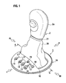
- Fig. 1 is a perspective view showing an overall structure of a first embodiment according to the present invention.
- Fig. 2 is a perspective view showing an indicator base of the first embodiment according to the present invention as viewed from a vehicle front area.
- Fig. 3 is a cross sectional view taken on line A-A of Fig. 1 showing a status under which a shift lever is shifted to a "P" range in the first embodiment according to the present invention.
- Fig. 4 is a cross sectional view taken on line A-A of Fig. 1 showing a status under which the shift lever is shifted to a "D" range in the first embodiment according to the present invention.
- Fig. 5 is a perspective view similar to Fig. 2 for illustrating a second embodiment according to the present invention.
- Fig. 6 is a perspective view similar to Fig. 2 for illustrating a third embodiment according to the present invention.
- Fig. 7 is a perspective view similar to Fig. 2 for illustrating another embodiment according to the present invention.
- Now, various embodiments according to the present invention are described below in detail with reference to the accompanying drawings.
- Figs. 1 to 4 show a first embodiment of an indicator of an AT/T vehicle according to the present invention. Fig. 1 is an overall perspective view of an indicator; Fig. 2 is an indicator base as viewed from a vehicle front; Fig. 3 is a cross sectional view taken on a line A-A of Fig. 1 showing a shift lever shifted in a "P" range; and Fig. 4 is a cross sectional view taken on the line A-A of Fig. 1 showing the shift lever shifted in a "D" range. Also in the following description, it is to be understood that such reference characters "R", "L", "FR" and "RR" refer to "a vehicle's rightward direction", " a vehicle's leftward direction", "a vehicle front" and "a vehicle rear", respectively.
- The indicator 1 of the present embodiment is disposed on a floor console section in an area near the driver's seat that is not shown.
- A
shift lever 2, inserted to the indicator in a vertical direction, is arranged to move in a vehicle's longitudinal direction to select each of "P", "R", "N" and "D" ranges in an automatic mode while making it possible to permit a shift of theshift lever 2 from a given "D" range in a vehicle's lateral direction for selecting ranges in a manual mode. - With the present embodiment, for a left-hand drive car, the
shift lever 2 is configured to move in a right direction (vehicle's right direction) in Fig. 1 for selecting the ranges in the manual mode. - The indicator 1 comprises an
indicator base 3, fixedly secured onto the floor console section, and an indicator upper 1A mounted on theindicator base 3 so as to cover the same. - With the present embodiment, the
indicator base 3 includes abase body 3A, substantially fixed onto the front console section, and aninner frame 3B disposed on a shift lever inserting portion of thebase body 3A. - The
base body 3A, theinner frame 3B and the indicator upper 1A are made of synthetic resin, and theinner frame 3B and the indicator upper 1A are fixed to thebase body 3A by means of a fixture means that is not shown. - The
inner frame 3B is formed with a bottom wall 3B1 as shown in Fig. 2. The bottom wall 3B1 is formed with first and secondmove permit holes move permit holes move permit hole 4A extends in a longitudinal direction to allow theshift lever 2 to select ranges "P" to "D" in an automatic mode. In addition, the secondmove permit hole 4B extends from a rear distal end of the firstmove permit hole 4A in a rightward direction as shown in Figs. 1 and 2, making it possible to select ranges in a manual mode of theshift lever 2 from the "D" range in the automatic range. - Further, an
annular flange portion 5 integrally stands upright from the bottom wall 3B1 so as to protrude upward in a given size and shape so as to surround the shift levermove permit hole 4, that is, in the same size and shape as those of anopen window portion 10 of the indicator upper 1A that will be described below in detail. - As shown in Fig. 3, the
annular flange portion 5 has a lower end whose outer periphery is formed with ajowl portion 5a to which alower terminal edge 20a of theshift lever boot 20, described below, is fixedly secured. - Further, first and
second slide plates base body 3A and theinner frame 3B. - With the
shift lever 2 inserted through thefirst slide plate 6, thefirst slide plate 6 slides in the vehicle's longitudinal direction with shifting operation of the shift lever displaced in the automatic mode along a guide rail, which is not shown, in the vehicle's longitudinal direction. - Further, the
shift lever 2 is also inserted through thesecond slide plate 7 that is held by thefirst slide plate 6. Thesecond slide plate 7 is structured such that as theshift lever 2 is moved for shifting operation in the automatic mode, thesecond slide plate 7 slides unitarily with thefirst slide plate 6 in the vehicle's longitudinal direction to cause theshift lever 2 to shift to the "D" range in the manual mode, thesecond slide plate 7 is caused to slide with the shifting operation of theshift lever 2 displaced in the vehicle's lateral direction (in the rightward direction in Fig. 1) with respect to thefirst slide plate 6. - The
second slide plate 7 has a rangenumber display portion 7a, colored in a red color representing a range position of theshift lever 2, which integrally extends in the vehicle's lateral direction as shown in FIG. 2. - Meanwhile, the indicator upper 1A is formed with the open window portion 10 (see Fig. 1) in a substantially oblong shape on a plane, through which the
shift lever 2 extends, with a size surrounding a move area of theshift lever 2 in the vehicle's longitudinal direction and the vehicle's lateral direction. - Accordingly, the
annular flange portion 5 is formed in the same annular configuration in the substantially oblong shape on the plane as that of theopen window portion 10 in an area nearly just below theopen window portion 10 of the indicator upper 1A and has a height to be close to a lower surface of the indicator upper 1A. - As shown in Fig. 1, further, a row of
range marks 11 to 14 for the shift positions "P" to "D" for the automatic mode is provided on the upper indicator 1 at an area on left side of theopen window portion 10 in a longitudinal direction thereof, with therange marks range mark 14. - Furthermore, a plurality of sight-through
windows 17 are formed in areas between sides of therange marks 11 to 14 and the range marks 15, 16 to allow therange display portion 7a of thesecond slide plate 7 to be visually checked. - Accordingly, the
range display portion 7a is set such that on moving theshift lever 2 to select the respective ranges "P', "R", "N" and "D" and selecting the range for the manual mode from the "D" range, a red colored range position is displayed at a position below the sight-throughwindows 17 in alignment with these range positions. - Here, the
shift lever boot 20, made of soft material such as leather or the like, is mounted in an area covering a circumferential portion of theopen window portion 10 of the indicator upper 1A and an upper end portion of theshift lever 2, that in, more particularly, to a position beneath aknob 2a. - The
shift lever boot 20 has a lower end formed in an oblong shape in cross section along the vehicle's longitudinal direction and is formed as a cover tapered in a decreased diameter as theshift lever boot 20 extends to an upper end thereof. The upper end of theshift lever boot 20 has a lever-clamping portion 21 for permitting theshift lever boot 20 to extend upward so as to fixedly secure the upper end of theshift lever boot 20 thereto. A bindingmember 22, made of a steel wire, is stitched on thelower terminal edge 20a in an annular pattern. - Before the indicator upper 1A is mounted onto the
indicator base 3 in fitting engagement therewith, theshift lever boot 20 is mounted such that a lower end portion of theshift lever boot 20 is fitted to an outer periphery of theannular flange portion 5 of theinner frame 3B upon which thebinding member 22, attached to thelower terminal edge 20a, is elastically fitted to thejowl portion 5a of theannular flange portion 5. In addition, when fixing the indicator upper 1A to theindicator base 3 in mating engagement, theshift lever boot 20 is pulled out of theopen window portion 10 in an upward direction. - Further, the upper end of the
shift lever boot 20 has an upper end mounted on an upper portion of theshift lever 2 in a locked state so as to allow the lever-clamping portion 21 to be inserted when the shift lever 2 through theindicator 2. At this moment, theknob 2a of theshift lever 2 is mounted onto the upper end of theshift lever 2 upon mounting theshift lever boot 20. - Here, a boot
penetration restricting device 30 is provided in an area inward theopen window portion 10 of the indicator 1 for restricting theshift lever boot 20 from flexing and penetrating into a downward area of theopen window portion 10. - With the present embodiment, as shown in Fig. 2, the boot
penetration restricting device 30 takes the form of a structure ofperipheral walls 30A that stand upright in given heights. Theperipheral walls 30A stand upright the bottom wall 3B1, present inward of theannular flange portion 5 of theinner frame 3B acting as the bottom wall of theindicator base 3 and exposed to theopen window portion 10 of the indicator upper 1A, in areas along an edge portion of the shift levermove permit hole 4. - The
peripheral walls 30A may be formed in an overall peripheral edge of the shift levermove permit hole 4 so as to stand upright with the same height as that of theannular flange portion 5 or slightly less than that of theannular flange portion 5 or may be formed in desired positions. - That is, the
shift lever boot 20 is formed in a size with an adequate margin so as to avoid a front side or a rear side of theshift lever boot 20 from stretching even under a situation where theshift lever boot 20 is moved in the vehicle front or vehicle rear direction in a great extent, that is, even when theshift lever 2 is moved to the "P" range or "D" range in the automatic mode. Therefore, the front side of theshift lever boot 20 has an increased flexing rate when theshift lever 2 is moved to the "P" range. In contrast, when the shift lever is shifted to the "D" range, the rear side of theshift lever boot 20 has an increased flexing rate. Thus, theperipheral walls 30A may be suffice to be provided merely in the front and rear areas of the shift levermove permit hole 4. - Therefore, with the present embodiment, the
peripheral walls 30A are formed on the bottom wall 3B1 jutting out to a front corner area inside theannular flange portion 5 and the bottom wall 3B1 jutting out to a rear corner area inside theannular flange portion 5, respectively. - That is, although the bottom wall 3B1 of the
inner frame 3B is formed in outside and inside areas of theannular flange portion 5, the bottom wall 3B1, having a substantially oblong shape as viewed on a plane, is formed in the right corner portion on the vehicle's front side and the left corner portion on the vehicle's rear side in areas inside theannular flange portion 5. Theperipheral walls 30A stand upright in the areas along peripheral edges of the bottom wall 3B1 formed in the front corner portion and the rear corner portion. - Further, as the boot
penetration restricting device 30, anupper end 5b of theannular flange portion 5 and an innerperipheral edge 10a of theopen window portion 10 pinch a lower end portion of theshift lever boot 20. - In addition, as the boot
penetration restricting device 30, the bindingmember 22, mounted to thelower terminal edge 20a of theshift lever boot 20, is resiliently fixed to thejowl portion 5a of theannular flange portion 5. - With the structure of the present embodiment set forth above, as the
shift lever 2 is shifted to the "P" range as shown in Fig. 3, the front side of theshift lever boot 20 is greatly flexed and, further, as theshift lever 2 is shifted to the "D" range as shown in Fig. 4, the rear side of theshift lever boot 20 is greatly flexed. Here, since the bootpenetration restricting device 30 is disposed inside theopen window portion 10 of the indicator 1 for restricting theshift lever boot 20 from flexing penetrating downward into the lower area, the bootpenetration restricting device 30 restricts the flexing and penetration of theshift lever boot 20. - As a result, even under a circumstance where a shift lever
move permit aperture 4 is located in close proximity to the lower area of theopen window portion 10, theshift lever 2 and the peripheral edge of the shift levermove permit aperture 4 can be reliably prevented from biting theshift lever boot 20. - With the present embodiment, further, since the boot
penetration restricting device 30 is structured with theperipheral walls 30A standing upright from the edge portion of the shift levermove permit aperture 4 with a given height, theperipheral walls 30A can be easily formed with the resultant advantage of a reduction in cost. - Furthermore, the lower end of the
shift lever boot 20 is mounted so as to be fitted and fixed to the outer periphery of theannular flange 5, formed on the bottom wall 3B1 of theindicator base 3, at a position substantially just below the peripheral edge of theopen window portion 10 of the indicator upper 1A such that theshift lever boot 20 extends upward of theopen window portion 10 of the indicator upper 1A. Therefore, theshift lever boot 20 can have increased quality sense without creating any gap between theshift lever boot 20 and the peripheral edge of theopen window portion 10. - Next, a second embodiment according to the present invention is described.
- With the second embodiment,
rib walls 30B are integrally formed with the bottom wall 3B1 of theindicator base 3, thereby forming the bootpenetration restricting device 30 as shown in Fig. 5. - A plurality of
rib walls 30B extend from an upper surface of the bottom wall 3B1, formed in areas covering the front side corner and the rear side corner inside theannular flange 5, in vehicle's longitudinal direction with the same height as that of theperipheral wall 30A. Even in this case, therib walls 30B can be easily formed, providing an advantage with low cost. - Next, a third embodiment according to the present invention is described. With the third embodiment, both of the
peripheral wall 30A, shown in Fig. 2, and theribs 30B, shown in Fig. 5, are formed thereby forming the bootpenetration restricting device 30 as shown in Fig. 6. Theperipheral wall 30A and theribs 30B are integrally formed on the bottom wall 3B1 of theindicator base 3 with the substantially same height. - Even with such a third embodiment, the presence of the
peripheral wall 30A and theribs 30B restricts the flexing and penetration of theshift lever boot 20. In addition, theperipheral wall 30A and theribs 30B can be easily formed, providing an advantage with low cost. - Meanwhile, although the present invention has been described with reference to the examples related to the various embodiments, the present invention is not limited to such embodiments and various other embodiments can be employed without departing from the scope of the present invention. For instance, a display of the shift position can be implemented using an electrical illumination type, such as LEDs or the like, in place of the mechanical type.
- Further, the
peripheral wall 30A and theribs 30B have heights with no need to be set to the same dimensions. Theperipheral wall 30A may have a larger height than those of theribs 30B. In an alternative, theribs 30B may have larger heights than that of theperipheral wall 30A. For instance, as shown in Fig. 7, theperipheral wall 30A may have a larger height than those of theribs 30B as shown in Fig. 7. This is because of the fact that as a shift-down is effectuated under the manual mode, theshift lever boot 20 is moves further rearward of the vehicle than the "D" range position followed by an increase in the amount of flexing. Also, increasing the heights of therib walls 30B extending along the vehicle's longitudinal direction enables theshift lever boot 20 to be restricted from penetrating in a further reliable fashion. - The entire contents of a
Japanese Patent Application No. P2005-340806 with a filing date of November 25, 2005 Japanese Patent Application No. P2006-249864 with a filing date of September 14, 2006 - Although the invention has been described above by reference to certain embodiments of the invention, the invention is not limited to the embodiments described above. Modifications and variations of the embodiments described above will occur to those skilled in the art, in light of the teachings. The scope of the invention is defined with reference to the following claims.
Claims (8)
- An indicator for an AT vehicle, comprising:a shift lever boot (20), made of soft material, which is attached onto a peripheral edge portion of an open window portion (10), through which a shift lever (2) extends, and an upper end portion (2a) of the shift lever (2) that protrudes upward through the open window portion (10); anda boot penetration restricting device (30) provided in an inside of the open window portion (10).
- The indicator for the AT vehicle according to claim 1, further comprising:an indicator base (3) having a shift lever move permit hole (4) including a first move permit hole (4A), enabling the shift lever (2) to move in a longitudinal direction of the vehicle for selecting a range in an automatic mode, and a second move permit hole (4B), enabling the shift lever (2) to move in a lateral direction of the vehicle from a given range in the automatic mode for selecting a range in a manual mode; andan indicator upper (1A) mounted on the indicator base (3) so as to cover an upper area thereof and having the open window portion (10) formed in a size surrounding travel areas of the shift lever (2) in the longitudinal direction and lateral direction of the vehicle;wherein the indicator base (3) is integrally formed with an annular flange portion (5) that upwardly protrudes at a position substantially just below a peripheral edge of the open window portion (10) of the indicator upper (1A); and
the boot penetration restricting device (30) is arranged to allow a lower end portion of the shift lever boot (20) to be fitted and fixed to an outer area of the annular flange portion (5). - The indicator for the AT vehicle according to claim 2, wherein:the boot penetration restricting device (30) is arranged to allow the lower end portion of the shift lever boot (20) to be clamped between an upper end of the annular flange portion (5) and an inner peripheral edge of the open window portion (10) of the indicator upper (1A).
- The indicator for the AT vehicle according to claims 2 or 3, wherein:the boot penetration restricting device (30) is arranged to allow a lower terminal edge (20a) of the shift lever boot (20) to be elastically engaged with a jowl portion (5a) formed on the annular flange portion (5).
- The indicator for the AT vehicle according to any one of preceding claims 2 to 4, wherein:the boot penetration restricting device (30) comprises:peripheral walls (30A) standing upright from the bottom wall (3B1) of the indicator base (3) with given heights in areas along the shift lever move permit hole (4).
- The indicator for the AT vehicle according to any one of preceding claims 2 to 4, wherein:the boot penetration restricting device (30) comprises:a plurality of ribs (30B) standing upright from an upper surface of the bottom wall (3B1) of the indicator base (3) with given heights and exposed to the open window portion (10) of the indicator upper (1A) that is formed with the shift lever move permit hole (4).
- The indicator for the AT vehicle according to any one of preceding claims 2 to 4, wherein:the boot penetration restricting device (30) comprises:peripheral walls (30A) standing upright from the bottom wall (3B1) of the indicator base (3) with given heights and exposed to the open window portion (10) of the indicator upper (1A) in areas along an edge portion of the shift lever move permit hole (4); anda plurality of rib walls (30B) standing upright from the bottom wall (3B1) of the indicator base (3) with given heights and exposed to the open window portion (10) of the indicator upper (1A) that is formed with the shift lever move permit hole (4).
- An indicator for an AT vehicle, wherein:a shift lever boot (20), made of soft material, is attached to an area covering a peripheral edge portion of the open window portion (10), through which the shift lever (20) extends, and an upper end portion (2a) of the shift lever (2) protruding upward from the open window portion, and a boot penetration restricting means (30) is provided to restrict the shift lever boot (20) from flexing and penetrating into a lower area of the open window portion (10).
Applications Claiming Priority (2)
| Application Number | Priority Date | Filing Date | Title |
|---|---|---|---|
| JP2005340806 | 2005-11-25 | ||
| JP2006249864A JP4769672B2 (en) | 2005-11-25 | 2006-09-14 | A / T vehicle indicator |
Publications (2)
| Publication Number | Publication Date |
|---|---|
| EP1790877A1 true EP1790877A1 (en) | 2007-05-30 |
| EP1790877B1 EP1790877B1 (en) | 2008-09-17 |
Family
ID=37605784
Family Applications (1)
| Application Number | Title | Priority Date | Filing Date |
|---|---|---|---|
| EP06024201A Active EP1790877B1 (en) | 2005-11-25 | 2006-11-22 | A/T selector with boot penetration restricting device |
Country Status (5)
| Country | Link |
|---|---|
| US (1) | US7650849B2 (en) |
| EP (1) | EP1790877B1 (en) |
| JP (1) | JP4769672B2 (en) |
| CN (1) | CN100443782C (en) |
| DE (1) | DE602006002798D1 (en) |
Families Citing this family (5)
| Publication number | Priority date | Publication date | Assignee | Title |
|---|---|---|---|---|
| JP5001102B2 (en) | 2007-09-18 | 2012-08-15 | 日立オートモティブシステムズ株式会社 | Power steering device |
| US9656546B2 (en) * | 2010-02-12 | 2017-05-23 | Ford Global Technologies, Llc | Vehicle shifter fluid diverter system |
| KR101382283B1 (en) * | 2012-03-05 | 2014-04-08 | 기아자동차(주) | Transmission indicator for vehicle |
| US11162577B2 (en) * | 2018-01-25 | 2021-11-02 | Sulochna Lalchandani | Console gear-shift spill guard for car, automobile, truck, and other vehicles |
| US11614160B1 (en) | 2022-03-15 | 2023-03-28 | Honda Motor Co., Ltd. | Shift gate assembly for vehicle including gate seal and method of using same |
Citations (5)
| Publication number | Priority date | Publication date | Assignee | Title |
|---|---|---|---|---|
| US3086609A (en) * | 1961-12-19 | 1963-04-23 | Jr Ernest Bryant | Gear shift lever cover and attaching bracket therefor |
| DE20217387U1 (en) * | 2002-11-12 | 2003-01-09 | Eissmann Gmbh | Protective device for the cover of a vehicle gear stick, comprises guide for the gear stick rod |
| EP1331421A2 (en) * | 2002-01-29 | 2003-07-30 | Adam Opel Ag | Shift lever device avoiding bellow pinching |
| JP2005001401A (en) | 2003-06-09 | 2005-01-06 | Tokai Rika Co Ltd | Range position indicating device for automatic transmission |
| FR2868996A1 (en) * | 2004-04-14 | 2005-10-21 | Bourbon Automobile Soc Par Act | Gearshift lever covering and protecting assembly for motor vehicle, has wedging wall whose edge is spaced from edge of flange at distance greater than thickness of flexible part but lesser than total thickness of flexible part and strip |
Family Cites Families (13)
| Publication number | Priority date | Publication date | Assignee | Title |
|---|---|---|---|---|
| US3285093A (en) * | 1964-06-15 | 1966-11-15 | Gen Motors Corp | Cover seal for shift console |
| JPS6178731A (en) * | 1985-05-20 | 1986-04-22 | Green Cross Corp:The | Heat-treated immunoglobulin preparation |
| US5862708A (en) * | 1996-02-16 | 1999-01-26 | Kabushiki Kaisha Tokai-Rika-Denki-Seisakusho | Shift lever device |
| US5855182A (en) * | 1996-09-30 | 1999-01-05 | General Motors Corporation | Floor shifter and console assembly |
| JP3578882B2 (en) * | 1997-01-31 | 2004-10-20 | 富士機工株式会社 | Operating device for automatic transmission |
| JP3420014B2 (en) * | 1997-04-02 | 2003-06-23 | 株式会社東海理化電機製作所 | Cover slide for shift lever device |
| DE19714495A1 (en) * | 1997-04-08 | 1998-10-15 | Bayerische Motoren Werke Ag | Dialing device with a display device |
| JPH1178581A (en) * | 1997-09-12 | 1999-03-23 | Kojima Press Co Ltd | Shift lever device |
| DE19938528A1 (en) * | 1999-08-13 | 2001-02-15 | Audi Ag | Control device for automatically and manually shiftable transmissions |
| JP2003276466A (en) * | 2002-03-22 | 2003-09-30 | Mitsuboshi Belting Ltd | Shift lever boot structure |
| US7017436B2 (en) * | 2002-10-10 | 2006-03-28 | General Motors Corporation | Boot assembly for a vehicle |
| JP4236515B2 (en) * | 2003-05-26 | 2009-03-11 | 小島プレス工業株式会社 | Shift lever device |
| DE202004009307U1 (en) * | 2004-06-11 | 2004-12-02 | Gaslock Gmbh | Device for indicating the gear engaged |
-
2006
- 2006-09-14 JP JP2006249864A patent/JP4769672B2/en active Active
- 2006-11-21 US US11/562,097 patent/US7650849B2/en active Active
- 2006-11-22 DE DE602006002798T patent/DE602006002798D1/en active Active
- 2006-11-22 EP EP06024201A patent/EP1790877B1/en active Active
- 2006-11-23 CN CNB2006101459087A patent/CN100443782C/en active Active
Patent Citations (6)
| Publication number | Priority date | Publication date | Assignee | Title |
|---|---|---|---|---|
| US3086609A (en) * | 1961-12-19 | 1963-04-23 | Jr Ernest Bryant | Gear shift lever cover and attaching bracket therefor |
| EP1331421A2 (en) * | 2002-01-29 | 2003-07-30 | Adam Opel Ag | Shift lever device avoiding bellow pinching |
| DE20217387U1 (en) * | 2002-11-12 | 2003-01-09 | Eissmann Gmbh | Protective device for the cover of a vehicle gear stick, comprises guide for the gear stick rod |
| JP2005001401A (en) | 2003-06-09 | 2005-01-06 | Tokai Rika Co Ltd | Range position indicating device for automatic transmission |
| US20050000310A1 (en) * | 2003-06-09 | 2005-01-06 | Nissan Motor Co., Ltd. | Automatic transmission shift range display structure |
| FR2868996A1 (en) * | 2004-04-14 | 2005-10-21 | Bourbon Automobile Soc Par Act | Gearshift lever covering and protecting assembly for motor vehicle, has wedging wall whose edge is spaced from edge of flange at distance greater than thickness of flexible part but lesser than total thickness of flexible part and strip |
Also Published As
| Publication number | Publication date |
|---|---|
| US7650849B2 (en) | 2010-01-26 |
| CN100443782C (en) | 2008-12-17 |
| JP2007168764A (en) | 2007-07-05 |
| DE602006002798D1 (en) | 2008-10-30 |
| US20070119360A1 (en) | 2007-05-31 |
| EP1790877B1 (en) | 2008-09-17 |
| JP4769672B2 (en) | 2011-09-07 |
| CN1971107A (en) | 2007-05-30 |
Similar Documents
| Publication | Publication Date | Title |
|---|---|---|
| US7650849B2 (en) | Indicator for A/T vehicle | |
| EP1790880B1 (en) | At selector cover | |
| US7854457B2 (en) | Gearshift finisher | |
| DE102019104672A1 (en) | Interior Cup Holder | |
| DE602004006022T2 (en) | LIGHT TURNING BUTTON | |
| US7201077B2 (en) | Automatic transmission shift range display structure | |
| US7467570B2 (en) | Slider member for automatic transmission shifters | |
| EP2628980A2 (en) | Indicator for vehicle transmission shift operating device, and vehicle transmission shift operating device | |
| US6182530B1 (en) | Shift lever device | |
| US7484433B2 (en) | Shift lever apparatus | |
| JP5120096B2 (en) | Shift lever peripheral structure | |
| EP1801464A2 (en) | Gearshift finisher | |
| JP4654276B2 (en) | Mounting structure for interior materials | |
| WO2018230279A1 (en) | Shift operation device | |
| JP5783534B2 (en) | Vehicle lighting device | |
| JP2022032457A (en) | Pillar garnish | |
| JP5047044B2 (en) | Meter mounting structure | |
| JPS6223302Y2 (en) | ||
| JP2013001147A (en) | Seat belt installing structure of vehicular seat | |
| JPH0835557A (en) | Housing for shift lever | |
| US20200286700A1 (en) | Switch Device Having Swinging-Type Operation | |
| CN1970330A (en) | At selector cover | |
| JP5516047B2 (en) | Front console structure | |
| DE202022107214U1 (en) | Emblem lighting arrangement | |
| JP2021138294A (en) | Sunroof device |
Legal Events
| Date | Code | Title | Description |
|---|---|---|---|
| PUAI | Public reference made under article 153(3) epc to a published international application that has entered the european phase |
Free format text: ORIGINAL CODE: 0009012 |
|
| 17P | Request for examination filed |
Effective date: 20061122 |
|
| AK | Designated contracting states |
Kind code of ref document: A1 Designated state(s): AT BE BG CH CY CZ DE DK EE ES FI FR GB GR HU IE IS IT LI LT LU LV MC NL PL PT RO SE SI SK TR |
|
| AX | Request for extension of the european patent |
Extension state: AL BA HR MK YU |
|
| 17Q | First examination report despatched |
Effective date: 20071031 |
|
| AKX | Designation fees paid |
Designated state(s): DE FR GB |
|
| GRAP | Despatch of communication of intention to grant a patent |
Free format text: ORIGINAL CODE: EPIDOSNIGR1 |
|
| GRAS | Grant fee paid |
Free format text: ORIGINAL CODE: EPIDOSNIGR3 |
|
| GRAA | (expected) grant |
Free format text: ORIGINAL CODE: 0009210 |
|
| AK | Designated contracting states |
Kind code of ref document: B1 Designated state(s): DE FR GB |
|
| REG | Reference to a national code |
Ref country code: GB Ref legal event code: FG4D |
|
| REF | Corresponds to: |
Ref document number: 602006002798 Country of ref document: DE Date of ref document: 20081030 Kind code of ref document: P |
|
| PLBE | No opposition filed within time limit |
Free format text: ORIGINAL CODE: 0009261 |
|
| STAA | Information on the status of an ep patent application or granted ep patent |
Free format text: STATUS: NO OPPOSITION FILED WITHIN TIME LIMIT |
|
| 26N | No opposition filed |
Effective date: 20090618 |
|
| REG | Reference to a national code |
Ref country code: FR Ref legal event code: PLFP Year of fee payment: 10 |
|
| REG | Reference to a national code |
Ref country code: FR Ref legal event code: PLFP Year of fee payment: 11 |
|
| REG | Reference to a national code |
Ref country code: FR Ref legal event code: PLFP Year of fee payment: 12 |
|
| REG | Reference to a national code |
Ref country code: FR Ref legal event code: PLFP Year of fee payment: 13 |
|
| REG | Reference to a national code |
Ref country code: DE Ref legal event code: R081 Ref document number: 602006002798 Country of ref document: DE Owner name: NISSAN MOTOR CO., LTD., YOKOHAMA-SHI, JP Free format text: FORMER OWNERS: FUJI KIKO CO. LTD., KOSAI, SHIZUOKA, JP; NISSAN MOTOR CO., LTD., YOKOHAMA-SHI, KANAGAWA-KEN, JP |
|
| REG | Reference to a national code |
Ref country code: GB Ref legal event code: 732E Free format text: REGISTERED BETWEEN 20230302 AND 20230308 |
|
| PGFP | Annual fee paid to national office [announced via postgrant information from national office to epo] |
Ref country code: GB Payment date: 20231019 Year of fee payment: 18 |
|
| PGFP | Annual fee paid to national office [announced via postgrant information from national office to epo] |
Ref country code: FR Payment date: 20231019 Year of fee payment: 18 Ref country code: DE Payment date: 20231019 Year of fee payment: 18 |