EP1790836A2 - Oil mist separator and cylinder head cover - Google Patents
Oil mist separator and cylinder head cover Download PDFInfo
- Publication number
- EP1790836A2 EP1790836A2 EP06024223A EP06024223A EP1790836A2 EP 1790836 A2 EP1790836 A2 EP 1790836A2 EP 06024223 A EP06024223 A EP 06024223A EP 06024223 A EP06024223 A EP 06024223A EP 1790836 A2 EP1790836 A2 EP 1790836A2
- Authority
- EP
- European Patent Office
- Prior art keywords
- valve
- oil
- chamber
- valve body
- mist separator
- Prior art date
- Legal status (The legal status is an assumption and is not a legal conclusion. Google has not performed a legal analysis and makes no representation as to the accuracy of the status listed.)
- Granted
Links
- 239000003595 mist Substances 0.000 title claims description 50
- 229920003002 synthetic resin Polymers 0.000 claims description 2
- 239000000057 synthetic resin Substances 0.000 claims description 2
- 230000001105 regulatory effect Effects 0.000 claims 1
- 230000002093 peripheral effect Effects 0.000 description 22
- 238000005192 partition Methods 0.000 description 5
- 239000010802 sludge Substances 0.000 description 4
- 229920002302 Nylon 6,6 Polymers 0.000 description 3
- 230000007246 mechanism Effects 0.000 description 3
- 230000004048 modification Effects 0.000 description 2
- 238000012986 modification Methods 0.000 description 2
- 230000008859 change Effects 0.000 description 1
- 230000000295 complement effect Effects 0.000 description 1
- 230000001419 dependent effect Effects 0.000 description 1
- 238000007599 discharging Methods 0.000 description 1
- 238000006073 displacement reaction Methods 0.000 description 1
- 239000002245 particle Substances 0.000 description 1
- 230000004044 response Effects 0.000 description 1
- 238000000638 solvent extraction Methods 0.000 description 1
- 230000007704 transition Effects 0.000 description 1
- 238000009423 ventilation Methods 0.000 description 1
Images


Classifications
-
- F—MECHANICAL ENGINEERING; LIGHTING; HEATING; WEAPONS; BLASTING
- F01—MACHINES OR ENGINES IN GENERAL; ENGINE PLANTS IN GENERAL; STEAM ENGINES
- F01M—LUBRICATING OF MACHINES OR ENGINES IN GENERAL; LUBRICATING INTERNAL COMBUSTION ENGINES; CRANKCASE VENTILATING
- F01M13/00—Crankcase ventilating or breathing
- F01M13/04—Crankcase ventilating or breathing having means for purifying air before leaving crankcase, e.g. removing oil
- F01M13/0416—Crankcase ventilating or breathing having means for purifying air before leaving crankcase, e.g. removing oil arranged in valve-covers
-
- F—MECHANICAL ENGINEERING; LIGHTING; HEATING; WEAPONS; BLASTING
- F01—MACHINES OR ENGINES IN GENERAL; ENGINE PLANTS IN GENERAL; STEAM ENGINES
- F01M—LUBRICATING OF MACHINES OR ENGINES IN GENERAL; LUBRICATING INTERNAL COMBUSTION ENGINES; CRANKCASE VENTILATING
- F01M13/00—Crankcase ventilating or breathing
- F01M13/04—Crankcase ventilating or breathing having means for purifying air before leaving crankcase, e.g. removing oil
-
- F—MECHANICAL ENGINEERING; LIGHTING; HEATING; WEAPONS; BLASTING
- F01—MACHINES OR ENGINES IN GENERAL; ENGINE PLANTS IN GENERAL; STEAM ENGINES
- F01M—LUBRICATING OF MACHINES OR ENGINES IN GENERAL; LUBRICATING INTERNAL COMBUSTION ENGINES; CRANKCASE VENTILATING
- F01M13/00—Crankcase ventilating or breathing
- F01M13/04—Crankcase ventilating or breathing having means for purifying air before leaving crankcase, e.g. removing oil
- F01M2013/0422—Separating oil and gas with a centrifuge device
- F01M2013/0427—Separating oil and gas with a centrifuge device the centrifuge device having no rotating part, e.g. cyclone
-
- F—MECHANICAL ENGINEERING; LIGHTING; HEATING; WEAPONS; BLASTING
- F01—MACHINES OR ENGINES IN GENERAL; ENGINE PLANTS IN GENERAL; STEAM ENGINES
- F01M—LUBRICATING OF MACHINES OR ENGINES IN GENERAL; LUBRICATING INTERNAL COMBUSTION ENGINES; CRANKCASE VENTILATING
- F01M13/00—Crankcase ventilating or breathing
- F01M13/04—Crankcase ventilating or breathing having means for purifying air before leaving crankcase, e.g. removing oil
- F01M2013/0488—Crankcase ventilating or breathing having means for purifying air before leaving crankcase, e.g. removing oil with oil trap in the return conduit to the crankcase
- F01M2013/0494—Crankcase ventilating or breathing having means for purifying air before leaving crankcase, e.g. removing oil with oil trap in the return conduit to the crankcase using check valves
Definitions
- the present invention relates to an oil mist separator for provision on a blow-by gas passage connecting the crank chamber of an engine with an intake passage, and a cylinder head cover provided with the oil mist separator.
- the oil mist separator is provided with a separating chamber 50 arranged on a blow-by gas passage.
- a valve mechanism 51 is arranged in a lower portion of the separating chamber 50.
- the separating chamber 50 communicates with a crank chamber via a gas introduction port 50a. Further, the separating chamber 50 communicates with an intake manifold via a gas discharge port 50b to which a positive crankcase ventilation (PCV) valve (not shown) is connected.
- An oil passage of the valve mechanism 51 communicates with the separating chamber 50 via an oil introduction port 52 positioned in an upper portion thereof.
- PCV positive crankcase ventilation
- an oil passage of the valve mechanism 51 communicates with a crank chamber via an oil discharge port 53 positioned in a lower portion thereof.
- a valve seat 55 is formed within a valve chamber 54 formed between the oil introduction port 52 and the oil discharge port 53, and a valve body 56 which can be brought into contact with and moved away from the valve seat 55 is accommodated within the valve chamber 54.
- the valve body 56 is provided with a first valve portion 57 arranged between the oil introduction port 52 and the valve seat 55, and a second valve portion 59 arranged between the valve seat 55 and the oil discharge port 53.
- the first valve portion 57 and the second valve portion 59 are coupled to each other by a valve rod 58.
- valve body 56 If pressure in the crank chamber becomes higher than the pressure in the intake manifold under a no-load operating state of an engine, the valve body 56 is urged upward due to the pressure difference between the crank chamber and the intake manifold, as shown in Fig. 9(a). Accordingly, the first valve portion 57 moves away from an upper surface of the valve seat 55, and the second valve portion 59 is brought into contact with a lower surface of the valve seat 55. In this state, oil is centrifugally separated from the blow-by gas flowing into the separating chamber 50 from the crank chamber via a blow-by gas passage (not shown) and a gas introduction port 50a, and the centrifugally separated oil stays within the valve chamber 54. On the other hand, the blow-by gas is discharged to the intake manifold via a gas discharge port 50b.
- valve body 56 is held at a position where neither the first valve portion 57 nor the second valve portion 59 is brought into contact with the valve seat 55, by a spring (not shown), as shown in Fig. 9(b). In this state, the oil reserved within the valve chamber 54 is returned to the crank chamber from the oil discharge port 53.
- the valve body 56 is urged downward on the basis of a differential pressure between the crank chamber and the intake manifold, as shown in Fig. 9(c). Further, the first valve portion 57 is pressed into the upper surface of the valve seat 55, and the second valve portion 59 is moved away from the lower surface of the valve seat 55. At this time, the separating chamber 50 communicates with the oil discharge port 53 of the valve chamber 54 via a notch 60 formed in the upper surface of the valve seat 55. In this state, the oil is centrifugally separated from the blow-by gas flowing into the separating chamber from the crank chamber, and the centrifugally separated oil is returned to the crank chamber from the inner side of the valve chamber 54 via the notch 60.
- valve body 56 There are cases where sludge attaches to the surfaces of the valve seat 55 and the valve body 56. In this case, there is a risk that the valve body 56 will be pressed into the valve seat 55 under the high-load operating state of the engine and firmly fixed to the valve seat 55 by the sludge so as to be immobile. In this case, even if the pressure in the intake manifold becomes lower than the pressure in the crank chamber in the no-load operating state or the low-load operating state of the engine, the valve body 56 will not detach from the valve seat 55. Accordingly, the separating chamber 50 communicates with the crank chamber only through the notch 60. As a result, the oil reserved within the valve chamber 54 is returned to the crank chamber only from the notch 60 little by little.
- An objective of the present invention is to provide an oil mist separator which reliably returns oil separated from blow-by gas to the engine, and a cylinder head cover provided with the oil mist separator. According to the present invention, this object is achieved by an oil mist separator as defined in claim 1 and a cylinder head cover as defined in claim 8.
- the dependent claims define preferred and advantageous embodiments of the invention.
- an oil mist separator provided on a blow-by gas passage connecting a crank chamber of an engine with an intake passage.
- the oil mist separator includes a separating portion and a check valve.
- the separating portion separates oil from blow-by gas introduced from the crank chamber.
- the check valve allows discharge of the oil to the crank chamber from the separating portion, and regulates inflow of the gas to the separating portion from the crank chamber.
- the check valve has a valve body arranged between an inner wall of a valve chamber and a valve seat. The valve body is displaced by a differential pressure between intake pressure and pressure of the crank chamber.
- the oil mist separator is structured such as to regulate inflow of the blow-by gas to the separating portion from the crank chamber in a valve closing state in which the valve body is brought into contact with the valve seat, and to discharge the oil to the crank chamber from the separating portion in a valve opening state in which the valve body is spaced away from the valve seat.
- the oil mist separator further includes holding means provided between the valve body and the inner wall of the valve chamber. In the valve opening state, the holding means holds the valve body in a state in which the valve body is away from an inner wall of the valve chamber.
- a cylinder head cover having the above oil mist separator is provided.
- the cylinder head cover is formed by a synthetic resin and integrally formed with the oil mist separator.
- a cylinder head cover 12 arranged on a cylinder 11 of an engine 10 is formed of nylon 66.
- An oil mist separator 13 for collecting oil from blow-by gas is formed in the cylinder head cover 12.
- the oil mist separator 13 is provided with a housing 14 formed in the cylinder head cover 12.
- a separating chamber 15 having a substantially conical shape is formed in the interior of the oil mist separator 13.
- a proximal portion of the separating chamber 15, and a distal portion narrower than the proximal portion are open.
- the separating chamber 15 is formed in such a manner that the distal portion is positioned in a lower side, and the separating chamber is inclined with respect to the vertical direction.
- a complementary angle of an inclination angle ⁇ 1 (0 ⁇ 1 ⁇ 90 degree) of an axis L of the separating chamber 15 with respect to a straight line extending in the vertical direction is preferably larger than an inclination angle ⁇ 2 of an inner peripheral surface at a position forming the separating chamber 15 in the housing 14 with respect to the axis L. In this case, no oil is reserved within the separating chamber 15.
- the proximal portion of the separating chamber 15 is closed by an end plate 16.
- a guide tube 17 is fitted into a hole formed in a center of the end plate 16, and the guide tube 17 is arranged within the separating chamber 15.
- the interior of the guide tube 17 defines a gas passage 18, and the gas passage 18 communicates with an outer portion of the housing 14.
- a partition wall 19 having a collar shape is integrally formed with the guide tube 17.
- a gap_having a circular ring shape is partitioned between a peripheral edge of the partition wall 19 and an inner peripheral surface of the housing 14.
- a separating portion is constructed by the housing 14 forming the separating chamber 15 and the guide tube 17.
- the separating chamber 15 communicates with an inner space of the cylinder head cover 12 via a gas introduction port 20 formed in a peripheral wall of the housing 14.
- the inner space of the cylinder head cover 12 communicates with a crank chamber via a blow-by gas passage (not shown) formed within the cylinder block of the engine 10.
- the gas introduction port 20 is open toward a tangential direction of the inner peripheral surface of the housing 14.
- the separating chamber 15 communicates within the cylinder head cover 12 via an oil discharge port 21 formed in its distal portion.
- connection member 23 forming a gas flow path 22 communicating with the gas passage 18 is attached to a corresponding position of an end plate 16.
- the connection member 23 is formed by nylon 66, and is welded to the housing 14.
- a known PCV valve 24 is installed in the gas flow path 22 in the connection member 23.
- a gas discharge port 24a of the PCV valve 24 communicates with an intake manifold via a gas pipe (not shown).
- An oil.case 26 serving as a reservoir portion formed by nylon 66 and having an oil chamber 25 is welded to a corresponding position of the housing 14, in the inner surface of the cylinder head cover 12. Oil discharged from the oil discharge port 21 is reserved in the oil chamber 25.
- a check valve 27 is arranged in a lower portion of the oil case 26, for allowing the oil discharge from the oil chamber 25 and preventing a back flow of the gas to the separating chamber 15 from the inner side of the cylinder head cover 12.
- the check valve 27 is provided with a peripheral wall 29 partitioning a valve chamber 28 having a substantially cylindrical shape.
- a lower end of the check valve 27 is open, and an end plate 30 constructing an inner wall of the valve chamber 28 is fitted and attached to the opening.
- An oil outlet 31 for discharging oil into the cylinder head cover 12 from the valve chamber 28 is formed in the end plate 30.
- An opening of the oil outlet 31 has a horizontal cross-section corresponding substantially to an asterisk shape (a star shape constituted by six protruding portions).
- valve port 32 connecting the valve chamber 28 with the oil chamber 25, and a valve seat 33 positioned in a lower side of the valve port 32 and communicating with the valve port 32.
- An inner surface of the valve seat 33 is widened toward a lower side from an upper side.
- a valve body 34 brought into contact with the valve seat 33 or moved away from the valve seat 33 on the basis of a displacement in the vertical direction within the valve chamber 28 so as to freely open and close the valve port 32.
- the valve body 34 is provided with a base plate 36 having a horizontal cross-section corresponding substantially to a star shape constituted by four protruding portions 35.
- a contact portion 37 having a semispherical shape is integrally formed with the valve body 34.
- the contact portion 37 can be brought into contact with the valve seat 33 or moved away from the valve seat 33.
- the interior of the contact portion 37 is hollow so as to reduce the weight the valve body 34.
- a leg portion 38 protruding toward the end plate 30 is integrally formed with the base plate 36.
- holding means is structured by each of the leg portions 38.
- Each of the leg portions 38 has a triangular vertical cross-section, and a width of each of the leg portions 38 is narrowed toward the distal end of the leg portion 38. Accordingly, the distal end of each of the leg portions 38 comes into line contact with the upper surface of the end plate 30 (the inner wall of the valve chamber).
- the valve body 34 and the oil outlet 31 are structured such that a part of the oil outlet 31 is always open, regardless of the position of the valve body 34, as shown in Fig. 2(a). This structure is achieved by the fact that the number of the protruding portions 35 in the horizontal cross-section of the valve body 34 is four, and the number of the protruding portions in the horizontal cross-section of the oil outlet 31 is six.
- the blow-by gas introduced into the separating chamber 15 form the gas introduction port 20 opening toward the tangential direction of the inner peripheral surface of the housing 14 is moved to the lower portion of the separating chamber 15 from the upper portion while whirling in a space having a substantially cylindrical shape and partitioned by the inner peripheral surface of the housing 14 and the outer peripheral surface of the guide tube 17.
- the oil mist is centrifugally separated from the blow-by gas moving while whirling, on the basis of the centrifugal force, and the separated oil mist attaches to the inner peripheral surface of the housing 14. Further, the oil mist also attaches to the outer peripheral surface of the guide tube 17 and the peripheral surface of the partition wall 19.
- the oil is continuously separated from the blow-by gas, and the separated oil is reserved in the oil chamber 25.
- the blow-by gas from which the oil mist has been centrifugally separated is moved to the upper portion of the separating chamber 15 through the passage between the inner peripheral surface of the housing 14 and the peripheral surface of the partition wall 19, and is thereafter introduced to the PCV valve 24 from the distal end of the guide tube 17 through the gas passage 18.
- the blow-by gas introduced to the PCV valve 24 is further sucked into the intake manifold.
- the valve body 34 of the check valve 27 is moved to the valve opening position shown in Fig. 4 from the valve closing position shown in Fig. 5 on the basis of its own weight, and the contact portion 37 is moved away from the valve seat 33 so as to open the valve port 32. Further, the valve body 34 is held in a state spaced away from the upper surface of the end plate 30 on the basis of the contact of each of the leg portions 38 with the end plate 30.
- the oil within the oil chamber 25 is discharged into the valve chamber 28 through the valve port 32.
- the oil discharged into the valve chamber 28 is discharged into the cylinder head cover 12 from the oil outlet 31 through the oil passage formed between the base plate 36 of the valve body 34 being spaced away from the end plate 30, and the end plate 30.
- the oil transported to the valve chamber 28 from the oil chamber 25 is smoothly returned into the cylinder head cover 12.
- valve body 34 is unlikely to be closely attached to the upper surface of the end plate 30. Further, if the pressure in the intake manifold becomes higher than the pressure in the crank chamber, the valve body 34 is easily detached from the upper surface of the end plate 30 so as to form the valve opening state.
- the valve body 34 detached from the valve seat 33 comes into line contact with the upper surface of the end plate 30, and the valve body 34 is held in the state of being spaced away from the end plate 30. Therefore, even if sludge is attached to the inner peripheral surface of the peripheral wall 29 and the valve body 34, the valve body 34 is not closely attached to the upper surface of the end plate 30 in the valve opening state in which the oil is discharged to the crank chamber from the separating chamber 15.
- the valve body 34 is easily detached from the upper surface of the end plate 30 so as to be brought into contact with the valve seat 33.
- the communication between the separating chamber 15 and the check valve 27 is more reliably shut off, the gas is not introduced into the separating chamber 15 from the crank chamber via the check valve 27.
- the oil is not returned to the separating chamber 15 from the valve chamber 28 of the check valve 27.
- the oil passage connecting,the valve chamber 28 with the oil outlet 31 is formed between the valve body 34 and the upper surface of the end plate 30 of the valve chamber 28. Therefore, the oil can be more reliably discharged to the crank chamber from the check valve 27 in the low-load operating state of the engine 10, and it is possible to more reliably return the oil separated from the blow-by gas to the engine.
- the valve body 34 and the oil outlet 31 have a star-shaped horizontal cross-section having three or more protruding portions. Further, the number of the protruding portions 35 in the horizontal cross-section of the valve body 34 is different from the number of the protruding portions in the horizontal cross-section of the oil outlet 31. Therefore, a part of the oil outlet 31 is always open. As a result, in the valve opening state of the check valve 27, an oil flow path extending along a displacing direction of the valve body 34 is formed by the opening of the oil outlet 31. Accordingly, a flow path resistance at a time when the oil is discharged to the crank chamber from the valve chamber 28 is lowered. Therefore, the oil can be more smoothly discharged to the crank chamber from the valve chamber 28 of the check valve 27, in the low-load operating state of the engine.
- the contact portion 37 of the valve body 34 which can be brought into contact with the valve seat 33 and be away from the valve seat 33 has a semispherical shape, and the inner surface of the valve seat 33 is expanded toward the lower side from the upper side.
- the contact portion 37 of the valve body 34 is brought into contact with the valve seat 33 at a time when the pressure in the crank chamber is higher than the pressure in the intake manifold, the valve port 32 of the valve seat 33 is more reliably closed. Accordingly, in the no-load operating state of the engine 10, the communication between the separating chamber 15 and the check valve 27 is more reliably shut off, and it is possible to more reliably prevent the oil from being returned to the separating chamber 15 from the valve chamber 28 of the check valve 27.
- the contact portion 37 comes into line contact with the valve seat 33 in the valve closing state, it is possible to prevent the contact portion 37 from being closely attached to the valve seat 33. Accordingly, when the pressure in the intake manifold becomes higher than the pressure in the crank chamber, the valve body 34 is more reliably moved away from the valve seat 33 so as to transition to the valve opening state.
- the contact portion 37 Since the contact portion 37 is hollow, the mass of the valve body 34 becomes smaller, and it is possible to improve the response of the check valve 27 to the change in differential pressure between the pressure in the intake manifold and the pressure in the crank chamber. Therefore, when the pressure in the intake manifold becomes lower than the pressure in the crank chamber due to the shift of the operating state of the engine 10, the valve body 34 is rapidly brought into contact with the valve seat 33, and the check valve 27 is rapidly switched to the valve closing state from the valve opening state. Accordingly, it is possible to more reliably collect the oil from the blow-by gas at a time when the operating state of the engine 10 is switched.
- the oil chamber 25 reserves the oil discharged from the separating chamber 15 and is formed between the separating chamber 15 and the valve chamber 28. Accordingly, when the check valve 27 is in the valve closing state, the oil separated in the separating chamber 15 is discharged to the oil chamber 25 from the separating chamber 15 so as to be reserved. Further, the oil is introduced to the valve chamber 28 of the check valve 27 from the oil chamber 25, in the valve opening state of the check valve 27. Accordingly, as is different from the case that the check valve 27 is arranged just below the oil discharge port 21, the oil is unlikely to be reserved in the separating chamber 15. Therefore, the oil once separated from the blow-by gas is unlikely to be carried to the intake manifold by the blow-by gas sucked into the intake manifold from the separating chamber 15. Accordingly, it is possible to more reliably return the oil separated from the blow-by gas to the engine 10.
- the oil mist separator 13 is formed in the cylinder head cover 12 in a state in which the housing 14 of the separating chamber 15 is integrally formed with the cylinder head cover 12. Accordingly, it is possible to make an occupied space of the oil mist separator 13 smaller, and it is possible to improve a mounting characteristic of the oil mist separator 13 to the vehicle.
- the oil mist separator 13 is integrally formed with the cylinder head cover 12 in such a manner that the separating chamber 15 having the conical shape is inclined with respect to a straight line extending along the vertical direction. Accordingly, the height of the oil mist separator 13 protruding to the upper side from the main body of the cylinder head cover 12 is reduced. Further, since the oil is not reserved within the separating chamber 15, the oil is not carried to the intake manifold from the separating chamber 15. Therefore, mounting characteristics to the vehicle are improved, and the oil is more reliably returned to the crank chamber.
- the present embodiment may be modified as follows.
- the structure may be made such that the oil chamber 25 is omitted, and the check valve 27 is arranged just below the oil discharge port 21 of the separating chamber 15.
- the number of the protruding portions may be changed in each of the horizontal cross-sections of the valve body 34 and the oil outlet 31. At this time, the number of protruding portions in the horizontal cross-section of the valve body 34 is different from the number of protruding portions in the horizontal cross-section of the oil outlet 31.
- the structure may be made, contrary to the embodiment mentioned above, such that the base plate 36 of the valve body 34 has a horizontal cross-section corresponding substantially to an asterisk shape, and the oil outlet 31 has a horizontal cross-section corresponding to a star shape provided with four protruding portions.
- the structure may be made such that a plurality of support pieces 40 formed in such a manner as to protrude toward the valve body 34 from the upper surface of the end plate 30 of the check valve 27 come into line contact with the lower surface of the base plate 36 of the valve body 34 in which the leg portions 38 are omitted, whereby the valve body 34 is maintained in the state of being spaced away from the upper surface of the end plate 30. Further, each of the leg portions 38 may come into point contact with the end plate 30, or the support piece 40 may come into point contact with the base plate 36.
- the housing 14 of the separating chamber 15 may be integrally formed with the cylinder head cover 12 in such a manner that the separating chamber 15 extends along the horizontal direction.
- the oil discharge port 21 is formed in the lower portion of the peripheral wall of the housing 14.
- the oil mist separator 13 structured independently from the cylinder head cover 12 may be installed on the side surface of the cylinder head cover 12 in such a manner that the separating chamber 15 extends along the vertical direction.
- This structure is suitable for a cascaded engine.
- the present invention may be embodied in an oil mist separator of a type that separates oil by rotating a plurality of impellers on the basis of flow pressure of blow-by gas introduced to the separating chamber and attaching the oil mist to the surface of each of the impellers.
Landscapes
- Engineering & Computer Science (AREA)
- Mechanical Engineering (AREA)
- General Engineering & Computer Science (AREA)
- Lubrication Details And Ventilation Of Internal Combustion Engines (AREA)
- Check Valves (AREA)
- Compressor (AREA)
Abstract
Description
- The present invention relates to an oil mist separator for provision on a blow-by gas passage connecting the crank chamber of an engine with an intake passage, and a cylinder head cover provided with the oil mist separator.
- Conventionally, this kind of oil mist separator is disclosed, for example, in
Japanese Laid-Open Patent Publication No. 2003-13723 chamber 50 arranged on a blow-by gas passage. Avalve mechanism 51 is arranged in a lower portion of theseparating chamber 50. The separatingchamber 50 communicates with a crank chamber via a gas introduction port 50a. Further, theseparating chamber 50 communicates with an intake manifold via agas discharge port 50b to which a positive crankcase ventilation (PCV) valve (not shown) is connected. An oil passage of thevalve mechanism 51 communicates with theseparating chamber 50 via anoil introduction port 52 positioned in an upper portion thereof. Further, an oil passage of thevalve mechanism 51 communicates with a crank chamber via anoil discharge port 53 positioned in a lower portion thereof. Avalve seat 55 is formed within avalve chamber 54 formed between theoil introduction port 52 and theoil discharge port 53, and avalve body 56 which can be brought into contact with and moved away from thevalve seat 55 is accommodated within thevalve chamber 54. Thevalve body 56 is provided with afirst valve portion 57 arranged between theoil introduction port 52 and thevalve seat 55, and asecond valve portion 59 arranged between thevalve seat 55 and theoil discharge port 53. Thefirst valve portion 57 and thesecond valve portion 59 are coupled to each other by avalve rod 58. - If pressure in the crank chamber becomes higher than the pressure in the intake manifold under a no-load operating state of an engine, the
valve body 56 is urged upward due to the pressure difference between the crank chamber and the intake manifold, as shown in Fig. 9(a). Accordingly, thefirst valve portion 57 moves away from an upper surface of thevalve seat 55, and thesecond valve portion 59 is brought into contact with a lower surface of thevalve seat 55. In this state, oil is centrifugally separated from the blow-by gas flowing into theseparating chamber 50 from the crank chamber via a blow-by gas passage (not shown) and a gas introduction port 50a, and the centrifugally separated oil stays within thevalve chamber 54. On the other hand, the blow-by gas is discharged to the intake manifold via agas discharge port 50b. - If the engine shifts to a low-load operating state from the no-load operating state, and the pressure in the intake manifold is substantially equal to the pressure in the crank chamber, the
valve body 56 is held at a position where neither thefirst valve portion 57 nor thesecond valve portion 59 is brought into contact with thevalve seat 55, by a spring (not shown), as shown in Fig. 9(b). In this state, the oil reserved within thevalve chamber 54 is returned to the crank chamber from theoil discharge port 53. - If the engine shifts to a high-load operating state, and the pressure in the intake manifold becomes higher than the pressure in the crank chamber, the
valve body 56 is urged downward on the basis of a differential pressure between the crank chamber and the intake manifold, as shown in Fig. 9(c). Further, thefirst valve portion 57 is pressed into the upper surface of thevalve seat 55, and thesecond valve portion 59 is moved away from the lower surface of thevalve seat 55. At this time, theseparating chamber 50 communicates with theoil discharge port 53 of thevalve chamber 54 via anotch 60 formed in the upper surface of thevalve seat 55. In this state, the oil is centrifugally separated from the blow-by gas flowing into the separating chamber from the crank chamber, and the centrifugally separated oil is returned to the crank chamber from the inner side of thevalve chamber 54 via thenotch 60. - There are cases where sludge attaches to the surfaces of the
valve seat 55 and thevalve body 56. In this case, there is a risk that thevalve body 56 will be pressed into thevalve seat 55 under the high-load operating state of the engine and firmly fixed to thevalve seat 55 by the sludge so as to be immobile. In this case, even if the pressure in the intake manifold becomes lower than the pressure in the crank chamber in the no-load operating state or the low-load operating state of the engine, thevalve body 56 will not detach from thevalve seat 55. Accordingly, theseparating chamber 50 communicates with the crank chamber only through thenotch 60. As a result, the oil reserved within thevalve chamber 54 is returned to the crank chamber only from thenotch 60 little by little. Therefore, in this case the oil centrifugally separated from the blow-by gas in correspondence with the operation of the engine overflows from thevalve chamber 54 so as to be reserved within theseparating chamber 50. Further, there is a problem in that the oil in theseparating chamber 50 is carried to the intake manifold by the blow-by gas. - An objective of the present invention is to provide an oil mist separator which reliably returns oil separated from blow-by gas to the engine, and a cylinder head cover provided with the oil mist separator.
According to the present invention, this object is achieved by an oil mist separator as defined inclaim 1 and a cylinder head cover as defined inclaim 8. The dependent claims define preferred and advantageous embodiments of the invention. - In accordance with one aspect of the present invention, an oil mist separator provided on a blow-by gas passage connecting a crank chamber of an engine with an intake passage is provided. The oil mist separator includes a separating portion and a check valve. The separating portion separates oil from blow-by gas introduced from the crank chamber. The check valve allows discharge of the oil to the crank chamber from the separating portion, and regulates inflow of the gas to the separating portion from the crank chamber. The check valve has a valve body arranged between an inner wall of a valve chamber and a valve seat. The valve body is displaced by a differential pressure between intake pressure and pressure of the crank chamber. The oil mist separator is structured such as to regulate inflow of the blow-by gas to the separating portion from the crank chamber in a valve closing state in which the valve body is brought into contact with the valve seat, and to discharge the oil to the crank chamber from the separating portion in a valve opening state in which the valve body is spaced away from the valve seat. The oil mist separator further includes holding means provided between the valve body and the inner wall of the valve chamber. In the valve opening state, the holding means holds the valve body in a state in which the valve body is away from an inner wall of the valve chamber.
- In accordance with another aspect of the present invention, a cylinder head cover having the above oil mist separator is provided. The cylinder head cover is formed by a synthetic resin and integrally formed with the oil mist separator.
- Other aspects and advantages of the invention will become apparent from the following description, taken in conjunction with the accompanying drawings, illustrating by way of example the principles of the invention.
- The invention, together with objects and advantages thereof, may best be understood by reference to the following description of the presently preferred embodiments together with the accompanying drawings in which:
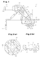
- Fig. 1 is a vertical cross-sectional view showing an oil mist separator in accordance with an embodiment;
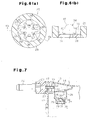
- Fig. 2(a) is a horizontal cross-sectional view showing a check valve;
- Fig. 2(b) is a cross-sectional view along a
line 2b-2b in Fig. 2(a); - Fig. 3(a) is a front elevational view showing a valve body;
- Fig. 3(b) is a side elevational view showing the valve body;
- Fig. 3(c) is a bottom view showing the valve body;
- Fig. 4 is a vertical cross-sectional view showing the check valve in a valve open state;
- Fig. 5 is a vertical cross-sectional view showing the check valve in a valve closed state;
- Fig. 6(a) is a horizontal cross-sectional view showing a check valve in accordance with another embodiment;
- Fig. 6(b) is a cross-sectional view along a
line 6b-6b in Fig. 6(a); - Fig. 7 is a vertical cross-sectional view showing an oil mist separator in accordance with a first modification;
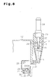
- Fig. 8 is a vertical cross-sectional view showing an oil mist separator in accordance with a second modification;
- Fig. 9(a) is a vertical cross-sectional view showing a prior art oil mist separator;
- Fig. 9(b) is a vertical cross-sectional view showing the prior art oil mist separator in accordance with a prior art; and
- Fig. 9(c) is a vertical cross-sectional view showing the prior art oil mist separator.
- Next, a description will be given of an embodiment according to the present invention with reference to Figs. 1 to 6(b). As shown in Fig. 1, a
cylinder head cover 12 arranged on acylinder 11 of anengine 10 is formed of nylon 66. Anoil mist separator 13 for collecting oil from blow-by gas is formed in thecylinder head cover 12. - The
oil mist separator 13 is provided with ahousing 14 formed in thecylinder head cover 12. A separatingchamber 15 having a substantially conical shape is formed in the interior of theoil mist separator 13. A proximal portion of theseparating chamber 15, and a distal portion narrower than the proximal portion are open. The separatingchamber 15 is formed in such a manner that the distal portion is positioned in a lower side, and the separating chamber is inclined with respect to the vertical direction. A complementary angle of an inclination angle θ1 (0<θ1<90 degree) of an axis L of the separatingchamber 15 with respect to a straight line extending in the vertical direction is preferably larger than an inclination angle θ2 of an inner peripheral surface at a position forming the separatingchamber 15 in thehousing 14 with respect to the axis L. In this case, no oil is reserved within the separatingchamber 15. - The proximal portion of the separating
chamber 15 is closed by anend plate 16. Aguide tube 17 is fitted into a hole formed in a center of theend plate 16, and theguide tube 17 is arranged within the separatingchamber 15. The interior of theguide tube 17 defines agas passage 18, and thegas passage 18 communicates with an outer portion of thehousing 14. In an outer peripheral surface of theguide tube 17, apartition wall 19 having a collar shape is integrally formed with theguide tube 17. A gap_having a circular ring shape is partitioned between a peripheral edge of thepartition wall 19 and an inner peripheral surface of thehousing 14. In the present embodiment, a separating portion is constructed by thehousing 14 forming the separatingchamber 15 and theguide tube 17. - The separating
chamber 15 communicates with an inner space of thecylinder head cover 12 via agas introduction port 20 formed in a peripheral wall of thehousing 14. The inner space of thecylinder head cover 12 communicates with a crank chamber via a blow-by gas passage (not shown) formed within the cylinder block of theengine 10. Thegas introduction port 20 is open toward a tangential direction of the inner peripheral surface of thehousing 14. The separatingchamber 15 communicates within thecylinder head cover 12 via anoil discharge port 21 formed in its distal portion. - In an outer surface of the
housing 14, aconnection member 23 forming agas flow path 22 communicating with thegas passage 18 is attached to a corresponding position of anend plate 16. Theconnection member 23 is formed by nylon 66, and is welded to thehousing 14. A knownPCV valve 24 is installed in thegas flow path 22 in theconnection member 23. Agas discharge port 24a of thePCV valve 24 communicates with an intake manifold via a gas pipe (not shown). - An
oil.case 26 serving as a reservoir portion formed by nylon 66 and having anoil chamber 25 is welded to a corresponding position of thehousing 14, in the inner surface of thecylinder head cover 12. Oil discharged from theoil discharge port 21 is reserved in theoil chamber 25. Acheck valve 27 is arranged in a lower portion of theoil case 26, for allowing the oil discharge from theoil chamber 25 and preventing a back flow of the gas to the separatingchamber 15 from the inner side of thecylinder head cover 12. - Next, a description will be given in detail of the
check valve 27. As shown in Figs. 2(a), 2(b) and 4, thecheck valve 27 is provided with aperipheral wall 29 partitioning avalve chamber 28 having a substantially cylindrical shape. A lower end of thecheck valve 27 is open, and anend plate 30 constructing an inner wall of thevalve chamber 28 is fitted and attached to the opening. Anoil outlet 31 for discharging oil into thecylinder head cover 12 from thevalve chamber 28 is formed in theend plate 30. An opening of theoil outlet 31 has a horizontal cross-section corresponding substantially to an asterisk shape (a star shape constituted by six protruding portions). Between thevalve chamber 28 and the oil chamber 25 (illustrated in Fig. 4), there is formed avalve port 32 connecting thevalve chamber 28 with theoil chamber 25, and avalve seat 33 positioned in a lower side of thevalve port 32 and communicating with thevalve port 32. An inner surface of thevalve seat 33 is widened toward a lower side from an upper side. Within thevalve chamber 28, there is accommodated avalve body 34 brought into contact with thevalve seat 33 or moved away from thevalve seat 33 on the basis of a displacement in the vertical direction within thevalve chamber 28 so as to freely open and close thevalve port 32. - As shown in Figs. 3(a) to 3(c), the
valve body 34 is provided with abase plate 36 having a horizontal cross-section corresponding substantially to a star shape constituted by four protrudingportions 35. On an upper surface of thevalve body 34, acontact portion 37 having a semispherical shape is integrally formed with thevalve body 34. Thecontact portion 37 can be brought into contact with thevalve seat 33 or moved away from thevalve seat 33. The interior of thecontact portion 37 is hollow so as to reduce the weight thevalve body 34. In a lower surface of a distal portion of each of the protrudingportions 35, aleg portion 38 protruding toward theend plate 30 is integrally formed with thebase plate 36. In the present embodiment, holding means is structured by each of theleg portions 38. Each of theleg portions 38 has a triangular vertical cross-section, and a width of each of theleg portions 38 is narrowed toward the distal end of theleg portion 38. Accordingly, the distal end of each of theleg portions 38 comes into line contact with the upper surface of the end plate 30 (the inner wall of the valve chamber). Thevalve body 34 and theoil outlet 31 are structured such that a part of theoil outlet 31 is always open, regardless of the position of thevalve body 34, as shown in Fig. 2(a). This structure is achieved by the fact that the number of the protrudingportions 35 in the horizontal cross-section of thevalve body 34 is four, and the number of the protruding portions in the horizontal cross-section of theoil outlet 31 is six. - Next, a description will be given of the operation of the
oil mist separator 13 structured as mentioned above. If the pressure of a crank chamber becomes higher than the pressure of an intake manifold under a no-load operating state of theengine 10, an upward urging force on the basis of the differential pressure between the crank chamber and the manifold is applied to thevalve body 34 of thecheck valve 27. Accordingly, thevalve body 34 is moved to a valve closing position shown in Fig. 5 from a valve opening position shown in Fig. 4, and thecontact portion 37 of thevalve body 34 is brought into contact with thevalve seat 33 so as to close the valve port 32.,At this time, the blow-by gas including oil mist within the crank chamber is introduced into the separatingchamber 15 from thegas introduction port 20 of theoil mist separator 13. The blow-by gas introduced into the separatingchamber 15 form thegas introduction port 20 opening toward the tangential direction of the inner peripheral surface of thehousing 14 is moved to the lower portion of the separatingchamber 15 from the upper portion while whirling in a space having a substantially cylindrical shape and partitioned by the inner peripheral surface of thehousing 14 and the outer peripheral surface of theguide tube 17. At this time, the oil mist is centrifugally separated from the blow-by gas moving while whirling, on the basis of the centrifugal force, and the separated oil mist attaches to the inner peripheral surface of thehousing 14. Further, the oil mist also attaches to the outer peripheral surface of theguide tube 17 and the peripheral surface of thepartition wall 19. Oil particles attached to the inner peripheral surface of thehousing 14, the outer peripheral surface of theguide tube 17 and the peripheral surface of thepartition wall 19 move to the lower side of the separatingchamber 15 along the inner peripheral surface of thehousing 14 due to gravitation in accordance with growth and enlargement, and are thereafter discharged to theoil chamber 25 from theoil discharge port 21. As mentioned above, the oil is continuously separated from the blow-by gas, and the separated oil is reserved in theoil chamber 25. On the other hand, the blow-by gas from which the oil mist has been centrifugally separated is moved to the upper portion of the separatingchamber 15 through the passage between the inner peripheral surface of thehousing 14 and the peripheral surface of thepartition wall 19, and is thereafter introduced to thePCV valve 24 from the distal end of theguide tube 17 through thegas passage 18. The blow-by gas introduced to thePCV valve 24 is further sucked into the intake manifold. - If the
engine 10 shifts to the low-load operating state from the no-load operating state, and the pressure in the intake manifold becomes substantially equal to the pressure in the crank chamber, the force applied to thevalve body 34 of thecheck valve 27 due to the differential pressure between the intake manifold and the crank chamber disappears. Accordingly, thevalve body 34 is moved to the valve opening position shown in Fig. 4 from the valve closing position shown in Fig. 5 on the basis of its own weight, and thecontact portion 37 is moved away from thevalve seat 33 so as to open thevalve port 32. Further, thevalve body 34 is held in a state spaced away from the upper surface of theend plate 30 on the basis of the contact of each of theleg portions 38 with theend plate 30. Therefore, the oil within theoil chamber 25 is discharged into thevalve chamber 28 through thevalve port 32. The oil discharged into thevalve chamber 28 is discharged into thecylinder head cover 12 from theoil outlet 31 through the oil passage formed between thebase plate 36 of thevalve body 34 being spaced away from theend plate 30, and theend plate 30. At this time, since a part of theoil outlet 31 is always open, the oil transported to thevalve chamber 28 from theoil chamber 25 is smoothly returned into thecylinder head cover 12. - If the pressure in the intake manifold becomes higher than the pressure in the crank chamber in the high-load operating state of the
engine 10, a downward force due to the differential pressure between the intake manifold and the crank chamber is applied to thevalve body 34 of thecheck valve 27. Accordingly, thevalve body 34 is pressed into the valve opening position shown in Fig. 4. Even in this state, the oil within thevalve chamber 28 is discharged into thecylinder head cover 12 through the oil passage between thevalve body 34 and theend plate 30. Accordingly, even in the high-load operating state of theengine 10, the oil within theoil chamber 25 is reliably returned within thecylinder head cover 12. Further, in this state, thevalve body 34 comes into line contact with the upper surface of theend plate 30 by the distal end of each of theleg portions 38. Therefore, even if sludge is attached to the upper surface of theend plate 30 and each of theleg portions 38 of thevalve body 34, thevalve body 34 is unlikely to be closely attached to the upper surface of theend plate 30. Further, if the pressure in the intake manifold becomes higher than the pressure in the crank chamber, thevalve body 34 is easily detached from the upper surface of theend plate 30 so as to form the valve opening state. - As mentioned above, in accordance with the present embodiment, in the valve opening stats of the
check valve 27 corresponding to the state in which the pressure in the intake manifold becomes higher than the pressure in the crank chamber, thevalve body 34 detached from thevalve seat 33 comes into line contact with the upper surface of theend plate 30, and thevalve body 34 is held in the state of being spaced away from theend plate 30. Therefore, even if sludge is attached to the inner peripheral surface of theperipheral wall 29 and thevalve body 34, thevalve body 34 is not closely attached to the upper surface of theend plate 30 in the valve opening state in which the oil is discharged to the crank chamber from the separatingchamber 15. Further, when the pressure in the crank chamber becomes higher than the pressure in the intake manifold, thevalve body 34 is easily detached from the upper surface of theend plate 30 so as to be brought into contact with thevalve seat 33. As a result, since the communication between the separatingchamber 15 and thecheck valve 27 is more reliably shut off, the gas is not introduced into the separatingchamber 15 from the crank chamber via thecheck valve 27. Accordingly, in the low-load operating state of theengine 10, the oil is not returned to the separatingchamber 15 from thevalve chamber 28 of thecheck valve 27. Further, in the valve opening state of thecheck valve 27, the oil passage connecting,thevalve chamber 28 with theoil outlet 31 is formed between thevalve body 34 and the upper surface of theend plate 30 of thevalve chamber 28. Therefore, the oil can be more reliably discharged to the crank chamber from thecheck valve 27 in the low-load operating state of theengine 10, and it is possible to more reliably return the oil separated from the blow-by gas to the engine. - The
valve body 34 and theoil outlet 31 have a star-shaped horizontal cross-section having three or more protruding portions. Further, the number of the protrudingportions 35 in the horizontal cross-section of thevalve body 34 is different from the number of the protruding portions in the horizontal cross-section of theoil outlet 31. Therefore, a part of theoil outlet 31 is always open. As a result, in the valve opening state of thecheck valve 27, an oil flow path extending along a displacing direction of thevalve body 34 is formed by the opening of theoil outlet 31. Accordingly, a flow path resistance at a time when the oil is discharged to the crank chamber from thevalve chamber 28 is lowered. Therefore, the oil can be more smoothly discharged to the crank chamber from thevalve chamber 28 of thecheck valve 27, in the low-load operating state of the engine. - The
contact portion 37 of thevalve body 34 which can be brought into contact with thevalve seat 33 and be away from thevalve seat 33 has a semispherical shape, and the inner surface of thevalve seat 33 is expanded toward the lower side from the upper side. In this case, since thecontact portion 37 of thevalve body 34 is brought into contact with thevalve seat 33 at a time when the pressure in the crank chamber is higher than the pressure in the intake manifold, thevalve port 32 of thevalve seat 33 is more reliably closed. Accordingly, in the no-load operating state of theengine 10, the communication between the separatingchamber 15 and thecheck valve 27 is more reliably shut off, and it is possible to more reliably prevent the oil from being returned to the separatingchamber 15 from thevalve chamber 28 of thecheck valve 27. Further, since thecontact portion 37 comes into line contact with thevalve seat 33 in the valve closing state, it is possible to prevent thecontact portion 37 from being closely attached to thevalve seat 33. Accordingly, when the pressure in the intake manifold becomes higher than the pressure in the crank chamber, thevalve body 34 is more reliably moved away from thevalve seat 33 so as to transition to the valve opening state. - Since the
contact portion 37 is hollow, the mass of thevalve body 34 becomes smaller, and it is possible to improve the response of thecheck valve 27 to the change in differential pressure between the pressure in the intake manifold and the pressure in the crank chamber. Therefore, when the pressure in the intake manifold becomes lower than the pressure in the crank chamber due to the shift of the operating state of theengine 10, thevalve body 34 is rapidly brought into contact with thevalve seat 33, and thecheck valve 27 is rapidly switched to the valve closing state from the valve opening state. Accordingly, it is possible to more reliably collect the oil from the blow-by gas at a time when the operating state of theengine 10 is switched. - The
oil chamber 25 reserves the oil discharged from the separatingchamber 15 and is formed between the separatingchamber 15 and thevalve chamber 28. Accordingly, when thecheck valve 27 is in the valve closing state, the oil separated in the separatingchamber 15 is discharged to theoil chamber 25 from the separatingchamber 15 so as to be reserved. Further, the oil is introduced to thevalve chamber 28 of thecheck valve 27 from theoil chamber 25, in the valve opening state of thecheck valve 27. Accordingly, as is different from the case that thecheck valve 27 is arranged just below theoil discharge port 21, the oil is unlikely to be reserved in the separatingchamber 15. Therefore, the oil once separated from the blow-by gas is unlikely to be carried to the intake manifold by the blow-by gas sucked into the intake manifold from the separatingchamber 15. Accordingly, it is possible to more reliably return the oil separated from the blow-by gas to theengine 10. - The
oil mist separator 13 is formed in thecylinder head cover 12 in a state in which thehousing 14 of the separatingchamber 15 is integrally formed with thecylinder head cover 12. Accordingly, it is possible to make an occupied space of theoil mist separator 13 smaller, and it is possible to improve a mounting characteristic of theoil mist separator 13 to the vehicle. - The
oil mist separator 13 is integrally formed with thecylinder head cover 12 in such a manner that the separatingchamber 15 having the conical shape is inclined with respect to a straight line extending along the vertical direction. Accordingly, the height of theoil mist separator 13 protruding to the upper side from the main body of thecylinder head cover 12 is reduced. Further, since the oil is not reserved within the separatingchamber 15, the oil is not carried to the intake manifold from the separatingchamber 15. Therefore, mounting characteristics to the vehicle are improved, and the oil is more reliably returned to the crank chamber. - The present embodiment may be modified as follows.
- The structure may be made such that the
oil chamber 25 is omitted, and thecheck valve 27 is arranged just below theoil discharge port 21 of the separatingchamber 15. - The number of the protruding portions may be changed in each of the horizontal cross-sections of the
valve body 34 and theoil outlet 31. At this time, the number of protruding portions in the horizontal cross-section of thevalve body 34 is different from the number of protruding portions in the horizontal cross-section of theoil outlet 31. For example, the structure may be made, contrary to the embodiment mentioned above, such that thebase plate 36 of thevalve body 34 has a horizontal cross-section corresponding substantially to an asterisk shape, and theoil outlet 31 has a horizontal cross-section corresponding to a star shape provided with four protruding portions. - As shown in Figs. 6(a) and 6(b), the structure may be made such that a plurality of
support pieces 40 formed in such a manner as to protrude toward thevalve body 34 from the upper surface of theend plate 30 of thecheck valve 27 come into line contact with the lower surface of thebase plate 36 of thevalve body 34 in which theleg portions 38 are omitted, whereby thevalve body 34 is maintained in the state of being spaced away from the upper surface of theend plate 30. Further, each of theleg portions 38 may come into point contact with theend plate 30, or thesupport piece 40 may come into point contact with thebase plate 36. - As shown in Fig. 7, the
housing 14 of the separatingchamber 15 may be integrally formed with thecylinder head cover 12 in such a manner that the separatingchamber 15 extends along the horizontal direction. In this case, theoil discharge port 21 is formed in the lower portion of the peripheral wall of thehousing 14. The structure mentioned above is suitable for an cascaded engine. - As shown in Fig. 8, the
oil mist separator 13 structured independently from thecylinder head cover 12 may be installed on the side surface of thecylinder head cover 12 in such a manner that the separatingchamber 15 extends along the vertical direction. This structure is suitable for a cascaded engine. - The present invention may be embodied in an oil mist separator of a type that separates oil by rotating a plurality of impellers on the basis of flow pressure of blow-by gas introduced to the separating chamber and attaching the oil mist to the surface of each of the impellers.
Claims (9)
- An oil mist separator (13) provided on a blow-by gas passage connecting a crank chamber of an engine (10) with an intake passage,
wherein said oil mist separator comprises: a separating portion (14, 15) separating oil from blow-by gas introduced from said crank chamber; a check valve (27) allowing discharge of the oil to the crank chamber from said separating portion (14, 15), and regulating inflow of the gas to the separating portion (14, 15) from the crank chamber,
wherein said check valve (27) has a valve body (34) arranged between an inner wall (30) of a valve chamber (28) and a valve seat (33), said valve body (34) being displaced by differential pressure between intake pressure and pressure of said crank chamber,
wherein the oil mist separator (13) is structured such as to regulate inflow of the blow-by gas to the separating portion (14, 15) from said crank chamber in a valve closing state in which said valve body (34) is brought into contact with said valve seat (33), and to discharge the oil to the crank chamber from the separating portion (14, 15) in a valve opening state in which said valve body (34) is spaced away from the valve seat (33),
the oil mist separator (13) being characterized by holding means (38; 40) provided between said valve body (34) and the inner wall (30) of said valve chamber (28), wherein, in said valve opening state, the holding means (38; 40) holds the valve body (34) in a state in which the valve body (34) is spaced away from an inner wall (30) of the valve chamber (28). - The oil mist separator (13) according to claim 1, characterized in that said holding means (38) is constituted by a plurality of leg portions (38) extending toward the inner wall (30) of the valve chamber (28) from said valve body (34), and each of said leg portions (38) comes into line contact or point contact with the inner wall (30) of said valve chamber (28).
- The oil mist separator (13) according to claim 1 or 2, characterized in that said check valve (27) is provided with an oil outlet (31) formed in the inner wall (30) of said valve chamber (28), and a part of said oil outlet (31) is always open.
- The oil mist separator (13) according to claim 3, characterized in that said valve body (34) and the oil outlet (31) each have a star-shaped horizontal cross-section constituted by three or more protruding portions (35), and the number of the protruding portions (35) in the horizontal cross-section of said valve body (34) is different from the number of the protruding portions (35) in the horizontal cross-section of said oil outlet (31).
- The oil mist separator (13) according to any one of claims 1 to 4, characterized in that said valve body (34) is brought into contact with said valve seat (33) and moved away from said valve seat (33), and is provided with a contact portion (37) having a semispherical shape.
- The oil mist separator (13) according to claim 5, characterized in that said contact portion (37) is hollow.
- The oil mist separator (13) according to any one of claims 1 to 6, characterized in that a reservoir portion (25, 26) reserving the oil discharged from said separating portion (14, 15) is provided between said separating portion (14, 15) and said check valve (27).
- A cylinder head cover (12) comprising the oil mist separator (13) according to any one of claims 1 to 7, the cylinder head cover (12) being characterized by being formed by a synthetic resin and integrally formed with said oil mist separator (13).
- The cylinder head cover (12) according to claim 8, characterized in that said separating portion (14, 15) is provided with a separating chamber (15), said separating chamber (15) has a conical shape, swirls the blow-by gas introduced from said crank chamber, and is arranged so as to be inclined with respect to a straight line extending along a vertical direction.
Applications Claiming Priority (1)
| Application Number | Priority Date | Filing Date | Title |
|---|---|---|---|
| JP2005340584A JP4506656B2 (en) | 2005-11-25 | 2005-11-25 | Oil mist separator and cylinder head cover |
Publications (3)
| Publication Number | Publication Date |
|---|---|
| EP1790836A2 true EP1790836A2 (en) | 2007-05-30 |
| EP1790836A3 EP1790836A3 (en) | 2007-12-26 |
| EP1790836B1 EP1790836B1 (en) | 2009-12-09 |
Family
ID=37560976
Family Applications (1)
| Application Number | Title | Priority Date | Filing Date |
|---|---|---|---|
| EP20060024223 Not-in-force EP1790836B1 (en) | 2005-11-25 | 2006-11-22 | Oil mist separator and cylinder head cover |
Country Status (3)
| Country | Link |
|---|---|
| EP (1) | EP1790836B1 (en) |
| JP (1) | JP4506656B2 (en) |
| DE (1) | DE602006010963D1 (en) |
Cited By (6)
| Publication number | Priority date | Publication date | Assignee | Title |
|---|---|---|---|---|
| FR2932843A1 (en) * | 2008-06-24 | 2009-12-25 | Mann & Hummel Gmbh | Oil drain device for oil separator in cylinder head cover of engine of motor vehicle, has ball movable between closed position and releasing position for permitting evacuation of oil contained in cannula under action of its gravity |
| EP2390477A1 (en) * | 2010-05-26 | 2011-11-30 | Elasis S.C.p.A. | Separator device for a system for recirculation of the blow-by gases of an internal combustion engine |
| WO2015197548A1 (en) * | 2014-06-27 | 2015-12-30 | Elringklinger Ag | Cylinder head cover and method for producing a cylinder head cover |
| US20160363015A1 (en) * | 2013-06-25 | 2016-12-15 | BRUSS Sealing Systems GmbH | Oil Separating Module in the Crankcase Ventilation System of a Combustion Engine |
| EP3336325A1 (en) * | 2016-12-16 | 2018-06-20 | Kubota Corporation | Engine head cover |
| CN108999675A (en) * | 2018-08-21 | 2018-12-14 | 宁波神通模塑有限公司 | A kind of oil drainage structure of oil mist separator |
Families Citing this family (4)
| Publication number | Priority date | Publication date | Assignee | Title |
|---|---|---|---|---|
| JP2009221858A (en) * | 2008-03-13 | 2009-10-01 | Kojima Press Co Ltd | Oil separator for blow-by gas |
| JP6135102B2 (en) * | 2012-11-22 | 2017-05-31 | アイシン精機株式会社 | Blow-by gas reduction device |
| JP6328517B2 (en) * | 2014-08-04 | 2018-05-23 | 愛三工業株式会社 | PCV valve |
| JP6520613B2 (en) * | 2015-09-28 | 2019-05-29 | トヨタ紡織株式会社 | Oil mist separator |
Citations (1)
| Publication number | Priority date | Publication date | Assignee | Title |
|---|---|---|---|---|
| US6202613B1 (en) | 1998-09-01 | 2001-03-20 | Kioritz Corporation | Four-stroke cycle internal combustion engine |
Family Cites Families (12)
| Publication number | Priority date | Publication date | Assignee | Title |
|---|---|---|---|---|
| JPS57193489U (en) * | 1981-06-03 | 1982-12-08 | ||
| JPS597212U (en) * | 1982-07-07 | 1984-01-18 | 日産自動車株式会社 | Oil separator for engine |
| JPS6030310U (en) * | 1983-08-03 | 1985-03-01 | アイシン精機株式会社 | oil separator |
| JPH01148010U (en) * | 1988-03-31 | 1989-10-13 | ||
| US5474541A (en) * | 1992-01-10 | 1995-12-12 | Astra Pharma, Inc. | Valved nozzle for re-usable reservoir of a flowable product |
| US6478019B2 (en) * | 1999-09-01 | 2002-11-12 | Nelson Industries, Inc. | Flat low profile diesel engine crankcase ventilation filter |
| DE10127817A1 (en) * | 2001-06-07 | 2002-12-12 | Bosch Gmbh Robert | Oil separating device has oil drain aperture in flow or cascade device before cyclone separating device |
| JP4558984B2 (en) * | 2001-06-28 | 2010-10-06 | ヤマハ発動機株式会社 | Blow-by gas separator |
| US6988510B2 (en) * | 2002-03-22 | 2006-01-24 | Halkey-Roberts Corporation | Disc check valve |
| JP4294949B2 (en) * | 2002-12-27 | 2009-07-15 | 日産ディーゼル工業株式会社 | Locker cover |
| JP4352228B2 (en) * | 2003-10-29 | 2009-10-28 | トヨタ自動車株式会社 | Breather equipment |
| DE102004004753A1 (en) * | 2004-01-30 | 2005-08-18 | Mann + Hummel Gmbh | Cylinder head cover |
-
2005
- 2005-11-25 JP JP2005340584A patent/JP4506656B2/en not_active Expired - Fee Related
-
2006
- 2006-11-22 DE DE200660010963 patent/DE602006010963D1/en active Active
- 2006-11-22 EP EP20060024223 patent/EP1790836B1/en not_active Not-in-force
Patent Citations (1)
| Publication number | Priority date | Publication date | Assignee | Title |
|---|---|---|---|---|
| US6202613B1 (en) | 1998-09-01 | 2001-03-20 | Kioritz Corporation | Four-stroke cycle internal combustion engine |
Cited By (11)
| Publication number | Priority date | Publication date | Assignee | Title |
|---|---|---|---|---|
| FR2932843A1 (en) * | 2008-06-24 | 2009-12-25 | Mann & Hummel Gmbh | Oil drain device for oil separator in cylinder head cover of engine of motor vehicle, has ball movable between closed position and releasing position for permitting evacuation of oil contained in cannula under action of its gravity |
| EP2390477A1 (en) * | 2010-05-26 | 2011-11-30 | Elasis S.C.p.A. | Separator device for a system for recirculation of the blow-by gases of an internal combustion engine |
| US9816410B2 (en) | 2010-05-26 | 2017-11-14 | Fiat Powertrain Technologies S.P.A. | Separator device for a system for recirculation of the blow-by gases of an internal combustion engine |
| US20160363015A1 (en) * | 2013-06-25 | 2016-12-15 | BRUSS Sealing Systems GmbH | Oil Separating Module in the Crankcase Ventilation System of a Combustion Engine |
| US10247068B2 (en) * | 2013-06-25 | 2019-04-02 | BRUSS Sealing Systems GmbH | Oil separating module in the crankcase ventilation system of a combustion engine |
| WO2015197548A1 (en) * | 2014-06-27 | 2015-12-30 | Elringklinger Ag | Cylinder head cover and method for producing a cylinder head cover |
| US10533517B2 (en) | 2014-06-27 | 2020-01-14 | Elringklinger Ag | Cylinder head cover and method for producing a cylinder head cover |
| EP3336325A1 (en) * | 2016-12-16 | 2018-06-20 | Kubota Corporation | Engine head cover |
| US10774704B2 (en) | 2016-12-16 | 2020-09-15 | Kubota Corporation | Engine head cover |
| CN108999675A (en) * | 2018-08-21 | 2018-12-14 | 宁波神通模塑有限公司 | A kind of oil drainage structure of oil mist separator |
| CN108999675B (en) * | 2018-08-21 | 2024-01-09 | 神通科技集团股份有限公司 | An oil leakage structure of an oil mist separator |
Also Published As
| Publication number | Publication date |
|---|---|
| JP2007146719A (en) | 2007-06-14 |
| EP1790836B1 (en) | 2009-12-09 |
| JP4506656B2 (en) | 2010-07-21 |
| EP1790836A3 (en) | 2007-12-26 |
| DE602006010963D1 (en) | 2010-01-21 |
Similar Documents
| Publication | Publication Date | Title |
|---|---|---|
| US8267071B2 (en) | Device for separating liquids from gases | |
| JP4344579B2 (en) | Cylinder head cover oil separator | |
| KR100636758B1 (en) | Oil separator for crankcase exhaust gas deoiling of internal combustion engines | |
| US7422612B2 (en) | Oil separator for the separation of oil from the crankcase ventilation gas of an internal combustion engine | |
| KR100405013B1 (en) | Oil separator for deoiling crankcase ventilation gases of an internal combustion engine | |
| US7080636B2 (en) | Oil separating device for a combustion engine | |
| EP1790836B1 (en) | Oil mist separator and cylinder head cover | |
| US20080196364A1 (en) | Oil Separating Apparatus and Cylinder Head Cover for an Internal Combustion Engine | |
| JP2009121281A (en) | Oil separator for internal combustion engine | |
| CN111051657A (en) | Cylinder Head Oil Separator (Controlled Flow Oil Separator) for Internal Combustion Engines | |
| CN102317585A (en) | Oil mist separator of an internal combustion engine | |
| JPH10176518A (en) | Gas-liquid separating device for engine of vibrator | |
| JP5482514B2 (en) | Oil separator | |
| JPH0676614U (en) | Oil mist separator | |
| JP3916433B2 (en) | Breather equipment | |
| JP6010011B2 (en) | Breather system for internal combustion engines | |
| CN111075535A (en) | Separator | |
| JP2002276328A (en) | Gas-liquid separation device for blow-by gas | |
| JP4352228B2 (en) | Breather equipment | |
| US8015966B2 (en) | Oil circulating device for internal combustion engine | |
| EP3543489B1 (en) | Internal combustion engine and method for manufacturing internal combustion engine | |
| JP6289885B2 (en) | Oil drain structure of oil mist separator | |
| EP0487203A2 (en) | Oil filter having gas separator | |
| JP2006250131A (en) | Engine oil separator | |
| JP2006070766A (en) | Blow-by gas reduction device |
Legal Events
| Date | Code | Title | Description |
|---|---|---|---|
| PUAI | Public reference made under article 153(3) epc to a published international application that has entered the european phase |
Free format text: ORIGINAL CODE: 0009012 |
|
| AK | Designated contracting states |
Kind code of ref document: A2 Designated state(s): AT BE BG CH CY CZ DE DK EE ES FI FR GB GR HU IE IS IT LI LT LU LV MC NL PL PT RO SE SI SK TR |
|
| AX | Request for extension of the european patent |
Extension state: AL BA HR MK YU |
|
| PUAL | Search report despatched |
Free format text: ORIGINAL CODE: 0009013 |
|
| AK | Designated contracting states |
Kind code of ref document: A3 Designated state(s): AT BE BG CH CY CZ DE DK EE ES FI FR GB GR HU IE IS IT LI LT LU LV MC NL PL PT RO SE SI SK TR |
|
| AX | Request for extension of the european patent |
Extension state: AL BA HR MK YU |
|
| 17P | Request for examination filed |
Effective date: 20080421 |
|
| AKX | Designation fees paid |
Designated state(s): DE FR GB |
|
| GRAP | Despatch of communication of intention to grant a patent |
Free format text: ORIGINAL CODE: EPIDOSNIGR1 |
|
| GRAS | Grant fee paid |
Free format text: ORIGINAL CODE: EPIDOSNIGR3 |
|
| GRAA | (expected) grant |
Free format text: ORIGINAL CODE: 0009210 |
|
| AK | Designated contracting states |
Kind code of ref document: B1 Designated state(s): DE FR GB |
|
| REG | Reference to a national code |
Ref country code: GB Ref legal event code: FG4D |
|
| REF | Corresponds to: |
Ref document number: 602006010963 Country of ref document: DE Date of ref document: 20100121 Kind code of ref document: P |
|
| PLBE | No opposition filed within time limit |
Free format text: ORIGINAL CODE: 0009261 |
|
| STAA | Information on the status of an ep patent application or granted ep patent |
Free format text: STATUS: NO OPPOSITION FILED WITHIN TIME LIMIT |
|
| 26N | No opposition filed |
Effective date: 20100910 |
|
| GBPC | Gb: european patent ceased through non-payment of renewal fee |
Effective date: 20101122 |
|
| REG | Reference to a national code |
Ref country code: FR Ref legal event code: ST Effective date: 20110801 |
|
| PG25 | Lapsed in a contracting state [announced via postgrant information from national office to epo] |
Ref country code: FR Free format text: LAPSE BECAUSE OF NON-PAYMENT OF DUE FEES Effective date: 20101130 |
|
| PG25 | Lapsed in a contracting state [announced via postgrant information from national office to epo] |
Ref country code: GB Free format text: LAPSE BECAUSE OF NON-PAYMENT OF DUE FEES Effective date: 20101122 |
|
| PGFP | Annual fee paid to national office [announced via postgrant information from national office to epo] |
Ref country code: DE Payment date: 20151118 Year of fee payment: 10 |
|
| REG | Reference to a national code |
Ref country code: DE Ref legal event code: R119 Ref document number: 602006010963 Country of ref document: DE |
|
| PG25 | Lapsed in a contracting state [announced via postgrant information from national office to epo] |
Ref country code: DE Free format text: LAPSE BECAUSE OF NON-PAYMENT OF DUE FEES Effective date: 20170601 |