EP1790827A1 - Tip shroud attachment for stator vane - Google Patents
Tip shroud attachment for stator vane Download PDFInfo
- Publication number
- EP1790827A1 EP1790827A1 EP06124935A EP06124935A EP1790827A1 EP 1790827 A1 EP1790827 A1 EP 1790827A1 EP 06124935 A EP06124935 A EP 06124935A EP 06124935 A EP06124935 A EP 06124935A EP 1790827 A1 EP1790827 A1 EP 1790827A1
- Authority
- EP
- European Patent Office
- Prior art keywords
- bushing
- tip shroud
- shroud segment
- assembly
- tip
- Prior art date
- Legal status (The legal status is an assumption and is not a legal conclusion. Google has not performed a legal analysis and makes no representation as to the accuracy of the status listed.)
- Granted
Links
- 238000003780 insertion Methods 0.000 description 2
- 230000037431 insertion Effects 0.000 description 2
- 229910000619 316 stainless steel Inorganic materials 0.000 description 1
- 230000003993 interaction Effects 0.000 description 1
- 239000000463 material Substances 0.000 description 1
- 239000000203 mixture Substances 0.000 description 1
- 238000012986 modification Methods 0.000 description 1
- 230000004048 modification Effects 0.000 description 1
- 229910001220 stainless steel Inorganic materials 0.000 description 1
- 239000010935 stainless steel Substances 0.000 description 1
- 238000003466 welding Methods 0.000 description 1
Images




Classifications
-
- F—MECHANICAL ENGINEERING; LIGHTING; HEATING; WEAPONS; BLASTING
- F01—MACHINES OR ENGINES IN GENERAL; ENGINE PLANTS IN GENERAL; STEAM ENGINES
- F01D—NON-POSITIVE DISPLACEMENT MACHINES OR ENGINES, e.g. STEAM TURBINES
- F01D9/00—Stators
- F01D9/02—Nozzles; Nozzle boxes; Stator blades; Guide conduits, e.g. individual nozzles
- F01D9/04—Nozzles; Nozzle boxes; Stator blades; Guide conduits, e.g. individual nozzles forming ring or sector
- F01D9/042—Nozzles; Nozzle boxes; Stator blades; Guide conduits, e.g. individual nozzles forming ring or sector fixing blades to stators
-
- F—MECHANICAL ENGINEERING; LIGHTING; HEATING; WEAPONS; BLASTING
- F05—INDEXING SCHEMES RELATING TO ENGINES OR PUMPS IN VARIOUS SUBCLASSES OF CLASSES F01-F04
- F05D—INDEXING SCHEME FOR ASPECTS RELATING TO NON-POSITIVE-DISPLACEMENT MACHINES OR ENGINES, GAS-TURBINES OR JET-PROPULSION PLANTS
- F05D2230/00—Manufacture
- F05D2230/20—Manufacture essentially without removing material
- F05D2230/23—Manufacture essentially without removing material by permanently joining parts together
- F05D2230/232—Manufacture essentially without removing material by permanently joining parts together by welding
Definitions
- This invention relates to turbine stator vanes and, particularly, to a mechanical attachment between a tip shroud segment and a group of stator vanes.
- Tip shrouds on stator vanes provide a deterministic flow path for the particular stator stage, and also serve to increase the stiffness of the vanes. It is customary to assemble arcuate shroud segments over a number of vanes (e.g., 5, 7 or more), with the segments collectively forming a 360° shroud. The tip shroud segments are typically welded to the tips of the vanes.
- each vane within a group of vanes to be covered by the shroud segment has a projecting tenon at its tip.
- the shroud segment is formed with corresponding holes that align with the tenons of the respective vanes.
- a bushing is seated in each of the shroud segment holes, and each bushing is formed with a center opening for receiving a respective one of the tenons.
- the center opening is counterbored, leaving an internal shoulder or seat for the tenon.
- the bushing is also formed with an external shoulder that allows the bushing to engage a shoulder surface of the corresponding shroud segment hole.
- This arrangement permits the bushing to be inserted into the shroud segment hole in a direction opposite the insertion direction of the vane tenons, with the external shoulder providing a stop limit to the bushing insertion.
- the vane tenons are subsequently welded to the internal bushing seat. Note that the bushings are not otherwise attached directly to the shroud segment but are nevertheless held in place radially by the tenon welds in one direction and the external shoulder engagement in the opposite direction.
- the present invention relates to a stator vane segment and tip shroud segment assembly comprising: a plurality of vanes, each having an airfoil portion and a radially inner tip, each tip formed with at least one radially inwardly projecting tenon; and a tip shroud segment extending over the radially inner tips of the vanes, said tip shroud segment formed with a plurality of holes, each hole fitted with a bushing that receives a respective one of the tenons.
- the invention in another aspect, relates to a stator vane segment and tip shroud segment assembly comprising: a plurality of vanes, each having an airfoil portion and a radially inner tip, each tip formed with at least one radially inwardly projecting tenon; a tip shroud segment extending over the radially inner tips of the vanes; the tip shroud segment formed with a plurality of holes, each hole fitted with a bushing that receives a respective one of the tenons; wherein the bushing is formed with an internal shoulder on which the respective tenon is seated; and wherein each bushing is formed with an external shoulder engaged by the tip shroud segment.
- the invention in still another aspect, relates to a stator vane segment and tip shroud segment assembly comprising: a plurality of vanes, each having an airfoil portion and a radially inner tip, each tip formed with at least one radially inwardly projecting tenon; a tip shroud segment extending over the radially inner tips of the vanes, the tip shroud segment formed with a plurality of holes, each hole fitted with a bushing that receives a respective one of the tenons; wherein each bushing is formed with an external shoulder engaged by the tip shroud; and wherein each bushing is formed with a center hole counterbored to provide an internal shoulder that provides a seat for the respective tenon and wherein the tenon is welded to the bushing at the internal shoulder.
- a stator vane and tip shroud segment assembly 10 includes a plurality of stator vanes 12, each of which includes a dove tail mounting portion 14, an airfoil portion 16, and a radially projecting tenon 18 (Figure 2) that projects from the radially inner tip 20 of the vane.
- the tenon 18 is round or oval in cross section and is formed approximately intermediate the forward and trailing edges 22, 24 of the airfoil portion.
- An arcuate tip shroud segment 26 spans and is attached to a selected member of stator vanes 12, such that the collective stator vane and tip shroud segments will form a 360° stator assembly.
- the arcuate tip shroud segment 26 is formed with a plurality of holes 28 that are appropriately located to align with the stator tenons 18. As best seen in Figure 3, the holes 28 are counterbored in a radially outward direction to create a radially inwardly facing shoulder 30 that is adapted to be engaged by a corresponding radially outwardly facing shoulder 32 on a bushing 34.
- the bushing 34 is correspondingly shaped to be received in the segment hole 28 (i.e., round or oval), and, as already indicated above, is formed with an external shoulder 32 that engages the corresponding shoulder 30 on the arcuate tip shroud segment 26.
- the bushing 34 is also formed with a center opening 36 that is counterbored to provide an annular (or oval)-shaped, radially outwardly facing seat 38 that is adapted to be engaged by the marginal edge of a respective tenon end face 40.
- the bushing may be constructed of 316 Stainless Steel while the airfoil portion 16 (including the tenons 18) and the tip shroud segment 26 may be constructed of a harder 403 Stainless Steel, but the material compositions may vary.
- Figures 4 and 5 illustrate another embodiment of a vane and tip shroud segment assembly 110 where the shapes of the tip shroud segment, bushing, and airfoil tenon as shown vary somewhat from the embodiment shown in Figures 1-3. Otherwise, the components and the interaction between the tip shroud segment, airfoil portion and bushing remains as previously described. For convenience, similar reference numerals are used, but with the prefix "1" added, to designate corresponding features, but no further description is required.
- FIG. 6 illustrates another vane segment configuration that incorporates the subject invention.
- similar reference numerals are used to designate similar components, where applicable, but with the prefix "2" added.
- the vane and tip shroud segment assembly 210 incorporates bushings 234 as described in connection with Figures 1-3 and this aspect of the assembly need not be repeated here.
- the portion (or dovetail mounting portions) 214 of the vanes are ganged together via a strap 244 and a plurality of bolts 246.
- the tenons could be formed with subtenons that project beyond the tenon end face and the extended subtenon may then be cold formed about the bushing end face.
- the tenon could be formed with a tapped hole with a bolt passing through the center opening of the bushing and into a threaded hole in the tenon.
Landscapes
- Engineering & Computer Science (AREA)
- Mechanical Engineering (AREA)
- General Engineering & Computer Science (AREA)
- Turbine Rotor Nozzle Sealing (AREA)
- Structures Of Non-Positive Displacement Pumps (AREA)
Abstract
Description
- This invention relates to turbine stator vanes and, particularly, to a mechanical attachment between a tip shroud segment and a group of stator vanes.
- Tip shrouds on stator vanes provide a deterministic flow path for the particular stator stage, and also serve to increase the stiffness of the vanes. It is customary to assemble arcuate shroud segments over a number of vanes (e.g., 5, 7 or more), with the segments collectively forming a 360° shroud. The tip shroud segments are typically welded to the tips of the vanes.
- In accordance with an exemplary embodiment of this invention, each vane within a group of vanes to be covered by the shroud segment has a projecting tenon at its tip. The shroud segment is formed with corresponding holes that align with the tenons of the respective vanes. A bushing is seated in each of the shroud segment holes, and each bushing is formed with a center opening for receiving a respective one of the tenons. The center opening is counterbored, leaving an internal shoulder or seat for the tenon. The bushing is also formed with an external shoulder that allows the bushing to engage a shoulder surface of the corresponding shroud segment hole. This arrangement permits the bushing to be inserted into the shroud segment hole in a direction opposite the insertion direction of the vane tenons, with the external shoulder providing a stop limit to the bushing insertion. The vane tenons are subsequently welded to the internal bushing seat. Note that the bushings are not otherwise attached directly to the shroud segment but are nevertheless held in place radially by the tenon welds in one direction and the external shoulder engagement in the opposite direction.
- Accordingly, in one aspect, the present invention relates to a stator vane segment and tip shroud segment assembly comprising: a plurality of vanes, each having an airfoil portion and a radially inner tip, each tip formed with at least one radially inwardly projecting tenon; and a tip shroud segment extending over the radially inner tips of the vanes, said tip shroud segment formed with a plurality of holes, each hole fitted with a bushing that receives a respective one of the tenons.
- In another aspect, the invention relates to a stator vane segment and tip shroud segment assembly comprising: a plurality of vanes, each having an airfoil portion and a radially inner tip, each tip formed with at least one radially inwardly projecting tenon; a tip shroud segment extending over the radially inner tips of the vanes; the tip shroud segment formed with a plurality of holes, each hole fitted with a bushing that receives a respective one of the tenons; wherein the bushing is formed with an internal shoulder on which the respective tenon is seated; and wherein each bushing is formed with an external shoulder engaged by the tip shroud segment.
- In still another aspect, the invention relates to a stator vane segment and tip shroud segment assembly comprising: a plurality of vanes, each having an airfoil portion and a radially inner tip, each tip formed with at least one radially inwardly projecting tenon; a tip shroud segment extending over the radially inner tips of the vanes, the tip shroud segment formed with a plurality of holes, each hole fitted with a bushing that receives a respective one of the tenons; wherein each bushing is formed with an external shoulder engaged by the tip shroud; and wherein each bushing is formed with a center hole counterbored to provide an internal shoulder that provides a seat for the respective tenon and wherein the tenon is welded to the bushing at the internal shoulder.
- Embodiments of the invention will now be described, by way of example only, in connection with the drawings identified below.
-
- FIGURE 1 discloses a perspective view of a shrouded stator vane segment in accordance with an exemplary embodiment of the invention;
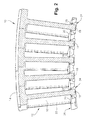
- FIGURE 2 is a cross-section taken along the line 2-2 of Figure 1;
- FIGURE 3 is a partial cross-section taken along the line 3-3 in Figure 1;
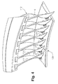
- Figure 4 is a perspective view of another exemplary embodiment of the invention; and
- Figure 5 is an enlarged detail similar to Figure 3 but taken from the assembly shown in Figure 4; and
- Figure 6 is a perspective view of still another embodiment of the invention.
- With reference initially to Figures 1-3, a stator vane and tip
shroud segment assembly 10 includes a plurality ofstator vanes 12, each of which includes a dovetail mounting portion 14, anairfoil portion 16, and a radially projecting tenon 18 (Figure 2) that projects from the radiallyinner tip 20 of the vane. Typically, thetenon 18 is round or oval in cross section and is formed approximately intermediate the forward andtrailing edges - An arcuate
tip shroud segment 26 spans and is attached to a selected member ofstator vanes 12, such that the collective stator vane and tip shroud segments will form a 360° stator assembly. - The arcuate
tip shroud segment 26 is formed with a plurality ofholes 28 that are appropriately located to align with thestator tenons 18. As best seen in Figure 3, theholes 28 are counterbored in a radially outward direction to create a radially inwardly facingshoulder 30 that is adapted to be engaged by a corresponding radially outwardly facingshoulder 32 on abushing 34. Thebushing 34 is correspondingly shaped to be received in the segment hole 28 (i.e., round or oval), and, as already indicated above, is formed with anexternal shoulder 32 that engages thecorresponding shoulder 30 on the arcuatetip shroud segment 26. Thebushing 34 is also formed with acenter opening 36 that is counterbored to provide an annular (or oval)-shaped, radially outwardly facingseat 38 that is adapted to be engaged by the marginal edge of a respectivetenon end face 40. - With the
bushings 34 inserted in thesegment holes 28 in direction A (Figure 3), theairfoil tenons 18 are inserted into the bushing in direction B until the tenons are fully engaged with theseats 38. Subsequently, eachairfoil tenon 18 is fixed to the bushing at theseat 38 byweld 42. It is significant that the bushing is not otherwise fixed to thetip shroud segment 26. As a result, some degree of movement between theairfoil portion 16 and thetip shroud segment 26 is permitted via bushing 34, thereby reducing stresses during operation. Note that the bushing is recessed relative to the radially inner face of the shroud segment so as not to protrude into the gas flowpath - In the exemplary embodiment, the bushing may be constructed of 316 Stainless Steel while the airfoil portion 16 (including the tenons 18) and the
tip shroud segment 26 may be constructed of a harder 403 Stainless Steel, but the material compositions may vary. - Figures 4 and 5 illustrate another embodiment of a vane and tip shroud segment assembly 110 where the shapes of the tip shroud segment, bushing, and airfoil tenon as shown vary somewhat from the embodiment shown in Figures 1-3. Otherwise, the components and the interaction between the tip shroud segment, airfoil portion and bushing remains as previously described. For convenience, similar reference numerals are used, but with the prefix "1" added, to designate corresponding features, but no further description is required.
- Figure 6 illustrates another vane segment configuration that incorporates the subject invention. In this figure, similar reference numerals are used to designate similar components, where applicable, but with the prefix "2" added. The vane and tip
shroud segment assembly 210 incorporatesbushings 234 as described in connection with Figures 1-3 and this aspect of the assembly need not be repeated here. In this embodiment, the portion (or dovetail mounting portions) 214 of the vanes are ganged together via astrap 244 and a plurality ofbolts 246. - In an alternative arrangement that does not require welding, the tenons could be formed with subtenons that project beyond the tenon end face and the extended subtenon may then be cold formed about the bushing end face. In yet another variation, the tenon could be formed with a tapped hole with a bolt passing through the center opening of the bushing and into a threaded hole in the tenon.
- While the invention has been described in connection with what is presently considered to be the most practical and preferred embodiment, it is to be understood that the invention is not to be limited to the disclosed embodiment, but on the contrary, is intended to cover various modifications and equivalent arrangements included within the spirit and scope of the appended claims.
Claims (10)
- A stator vane segment and tip shroud segment assembly (10) comprising:a plurality of vanes (12), each having an airfoil portion 16 and a radially inner tip (20), each tip formed with at least one radially inwardly projecting tenon (18); anda tip shroud segment (26) extending over the radially inner tips (20) of the vanes, said tip shroud segment (26) formed with a plurality of holes (28), each hole fitted with a bushing (34) that receives a respective one of said tenons (18).
- The assembly of claim 1 wherein said tenons (18) are attached directly to said bushings (34).
- The assembly of claim 1 wherein said bushing (34) is formed with an internal seat (38) on which the respective tenon is seated.
- The assembly of claim 1 wherein each bushing (34) is recessed relative to a radially innermost surface of said tip shroud segment (26) such that said bushing does not protrude into a flowpath along the airfoil portions of the vanes (12).
- The assembly of claim 3 wherein each bushing (34) is recessed relative to a radially innermost surface of said tip shroud segment (26) such that said bushing does not protrude into a flowpath along the airfoil portions of the vanes (12).
- The assembly of claim 1 wherein each bushing (34) is formed with an external shoulder (32) engaged by said tip shroud segment (26).
- The assembly of claim 3 wherein each bushing (34) is formed with an external shoulder (32) engaged by said tip shroud segment (26).
- The assembly of claim 1 wherein each bushing (34) is formed with a center hole counterbored to provide an internal shoulder that provides a seat (38) for the respective tenon (18) and wherein said tenon (18) is welded to said bushing at said internal shoulder.
- The assembly of claim 2 wherein said bushings (34) are not otherwise attached to said tip shroud segment.
- The assembly of claim 1 wherein said tenons (18) are welded to said bushings.
Applications Claiming Priority (1)
| Application Number | Priority Date | Filing Date | Title |
|---|---|---|---|
| US11/288,400 US20070122274A1 (en) | 2005-11-29 | 2005-11-29 | Tip shroud attachment for stator vane |
Publications (2)
| Publication Number | Publication Date |
|---|---|
| EP1790827A1 true EP1790827A1 (en) | 2007-05-30 |
| EP1790827B1 EP1790827B1 (en) | 2009-04-15 |
Family
ID=37695991
Family Applications (1)
| Application Number | Title | Priority Date | Filing Date |
|---|---|---|---|
| EP06124935A Not-in-force EP1790827B1 (en) | 2005-11-29 | 2006-11-28 | Tip shroud attachment for stator vane |
Country Status (4)
| Country | Link |
|---|---|
| US (1) | US20070122274A1 (en) |
| EP (1) | EP1790827B1 (en) |
| JP (1) | JP2007146848A (en) |
| DE (1) | DE602006006271D1 (en) |
Cited By (2)
| Publication number | Priority date | Publication date | Assignee | Title |
|---|---|---|---|---|
| US8696311B2 (en) | 2011-03-29 | 2014-04-15 | Pratt & Whitney Canada Corp. | Apparatus and method for gas turbine engine vane retention |
| US9506361B2 (en) | 2013-03-08 | 2016-11-29 | Pratt & Whitney Canada Corp. | Low profile vane retention |
Families Citing this family (5)
| Publication number | Priority date | Publication date | Assignee | Title |
|---|---|---|---|---|
| JP5091615B2 (en) * | 2007-10-15 | 2012-12-05 | 三菱重工業株式会社 | Stator blade ring segment assembly method, stator blade ring segment, connecting member, welding method |
| US8662819B2 (en) * | 2008-12-12 | 2014-03-04 | United Technologies Corporation | Apparatus and method for preventing cracking of turbine engine cases |
| DE102015205424A1 (en) * | 2015-03-25 | 2016-09-29 | Ebm-Papst Mulfingen Gmbh & Co. Kg | vane |
| CN110234864B (en) | 2016-11-11 | 2021-08-13 | 布里格斯斯特拉顿公司 | Cyclone Air Filter Assembly for Engine |
| WO2019147219A1 (en) | 2018-01-23 | 2019-08-01 | Siemens Aktiengesellschaft | Slide on shroud cover segments for gas turbine compressor stator vanes |
Citations (3)
| Publication number | Priority date | Publication date | Assignee | Title |
|---|---|---|---|---|
| US5411368A (en) * | 1993-11-08 | 1995-05-02 | Allied-Signal Inc. | Ceramic-to-metal stator vane assembly with braze |
| US5421703A (en) * | 1994-05-25 | 1995-06-06 | General Electric Company | Positively retained vane bushing for an axial flow compressor |
| EP1205638A2 (en) * | 2000-11-09 | 2002-05-15 | General Electric Company | Inlet guide vane and shroud support contact |
Family Cites Families (9)
| Publication number | Priority date | Publication date | Assignee | Title |
|---|---|---|---|---|
| US4395195A (en) * | 1980-05-16 | 1983-07-26 | United Technologies Corporation | Shroud ring for use in a gas turbine engine |
| US4832568A (en) * | 1982-02-26 | 1989-05-23 | General Electric Company | Turbomachine airfoil mounting assembly |
| US4798320A (en) * | 1985-09-20 | 1989-01-17 | Allied-Signal Inc. | Ceramic-metal brazed joint for turbochargers |
| US5593275A (en) * | 1995-08-01 | 1997-01-14 | General Electric Company | Variable stator vane mounting and vane actuation system for an axial flow compressor of a gas turbine engine |
| US6269540B1 (en) * | 1998-10-05 | 2001-08-07 | National Research Council Of Canada | Process for manufacturing or repairing turbine engine or compressor components |
| US6128820A (en) * | 1998-10-20 | 2000-10-10 | General Electric Co. | Method of repairing damaged turbine rotor wheels using differentially controlled temperatures |
| US6086327A (en) * | 1999-01-20 | 2000-07-11 | Mack Plastics Corporation | Bushing for a jet engine vane |
| US6526657B2 (en) * | 2001-05-07 | 2003-03-04 | General Electric Company | Methods for automated peening of tenons connecting turbine buckets and cover plates |
| US6682299B2 (en) * | 2001-11-15 | 2004-01-27 | General Electric Company | Variable stator vane support arrangement |
-
2005
- 2005-11-29 US US11/288,400 patent/US20070122274A1/en not_active Abandoned
-
2006
- 2006-11-28 EP EP06124935A patent/EP1790827B1/en not_active Not-in-force
- 2006-11-28 DE DE602006006271T patent/DE602006006271D1/en not_active Expired - Fee Related
- 2006-11-29 JP JP2006320957A patent/JP2007146848A/en not_active Withdrawn
Patent Citations (3)
| Publication number | Priority date | Publication date | Assignee | Title |
|---|---|---|---|---|
| US5411368A (en) * | 1993-11-08 | 1995-05-02 | Allied-Signal Inc. | Ceramic-to-metal stator vane assembly with braze |
| US5421703A (en) * | 1994-05-25 | 1995-06-06 | General Electric Company | Positively retained vane bushing for an axial flow compressor |
| EP1205638A2 (en) * | 2000-11-09 | 2002-05-15 | General Electric Company | Inlet guide vane and shroud support contact |
Cited By (2)
| Publication number | Priority date | Publication date | Assignee | Title |
|---|---|---|---|---|
| US8696311B2 (en) | 2011-03-29 | 2014-04-15 | Pratt & Whitney Canada Corp. | Apparatus and method for gas turbine engine vane retention |
| US9506361B2 (en) | 2013-03-08 | 2016-11-29 | Pratt & Whitney Canada Corp. | Low profile vane retention |
Also Published As
| Publication number | Publication date |
|---|---|
| DE602006006271D1 (en) | 2009-05-28 |
| US20070122274A1 (en) | 2007-05-31 |
| EP1790827B1 (en) | 2009-04-15 |
| JP2007146848A (en) | 2007-06-14 |
Similar Documents
| Publication | Publication Date | Title |
|---|---|---|
| JP6692609B2 (en) | Turbine bucket assembly and turbine system | |
| US8430629B2 (en) | Assembly for a stator stage of a turbomachine, the assembly comprising an outer shroud and at least one stationary vane | |
| US7520055B2 (en) | Method for manufacturing a stator or rotor component | |
| EP2204539B1 (en) | Stator assembly for a gas turbine engine | |
| US8206094B2 (en) | Stationary blade ring of axial compressor | |
| EP1657405B1 (en) | Stator vane assembly for a gas turbine | |
| EP2573325A1 (en) | Impingement cooling of turbine blades or vanes | |
| US20150345307A1 (en) | Turbine bucket assembly and turbine system | |
| US8807927B2 (en) | Clearance flow control assembly having rail member | |
| EP2620591A2 (en) | Gas turbine engine stator vane assembly with inner shroud | |
| US20150345309A1 (en) | Turbine bucket assembly and turbine system | |
| JP4998690B2 (en) | Double layer tip cap | |
| US10443389B2 (en) | Turbine blade having improved flutter capability and increased turbine stage output | |
| EP1790827A1 (en) | Tip shroud attachment for stator vane | |
| US8821125B2 (en) | Turbine blade having improved flutter capability and increased turbine stage output | |
| US8556581B2 (en) | Stator vane assembly | |
| US20120057988A1 (en) | Rotor for a turbomachine | |
| JP4481822B2 (en) | Manufacturing method of stator blade component | |
| US9376935B2 (en) | Gas turbine engine mounting ring | |
| EP3971404B1 (en) | Exhaust duct of gas turbine engine | |
| JP2005291208A (en) | Integrated cover nozzle with mounted overcover | |
| US20150345310A1 (en) | Turbine bucket assembly and turbine system | |
| US20240183279A1 (en) | Group of stator vanes | |
| CN112969842A (en) | Air flow straightener unit comprising a centering and attachment plate |
Legal Events
| Date | Code | Title | Description |
|---|---|---|---|
| PUAI | Public reference made under article 153(3) epc to a published international application that has entered the european phase |
Free format text: ORIGINAL CODE: 0009012 |
|
| AK | Designated contracting states |
Kind code of ref document: A1 Designated state(s): AT BE BG CH CY CZ DE DK EE ES FI FR GB GR HU IE IS IT LI LT LU LV MC NL PL PT RO SE SI SK TR |
|
| AX | Request for extension of the european patent |
Extension state: AL BA HR MK YU |
|
| 17P | Request for examination filed |
Effective date: 20071130 |
|
| AKX | Designation fees paid |
Designated state(s): CH DE FR GB LI |
|
| 17Q | First examination report despatched |
Effective date: 20080114 |
|
| GRAP | Despatch of communication of intention to grant a patent |
Free format text: ORIGINAL CODE: EPIDOSNIGR1 |
|
| GRAS | Grant fee paid |
Free format text: ORIGINAL CODE: EPIDOSNIGR3 |
|
| GRAA | (expected) grant |
Free format text: ORIGINAL CODE: 0009210 |
|
| AK | Designated contracting states |
Kind code of ref document: B1 Designated state(s): CH DE FR GB LI |
|
| REG | Reference to a national code |
Ref country code: GB Ref legal event code: FG4D Ref country code: CH Ref legal event code: EP |
|
| REF | Corresponds to: |
Ref document number: 602006006271 Country of ref document: DE Date of ref document: 20090528 Kind code of ref document: P |
|
| PLBE | No opposition filed within time limit |
Free format text: ORIGINAL CODE: 0009261 |
|
| STAA | Information on the status of an ep patent application or granted ep patent |
Free format text: STATUS: NO OPPOSITION FILED WITHIN TIME LIMIT |
|
| 26N | No opposition filed |
Effective date: 20100118 |
|
| REG | Reference to a national code |
Ref country code: FR Ref legal event code: ST Effective date: 20100730 |
|
| PG25 | Lapsed in a contracting state [announced via postgrant information from national office to epo] |
Ref country code: FR Free format text: LAPSE BECAUSE OF NON-PAYMENT OF DUE FEES Effective date: 20091130 |
|
| PG25 | Lapsed in a contracting state [announced via postgrant information from national office to epo] |
Ref country code: DE Free format text: LAPSE BECAUSE OF NON-PAYMENT OF DUE FEES Effective date: 20100601 |
|
| REG | Reference to a national code |
Ref country code: CH Ref legal event code: PL |
|
| GBPC | Gb: european patent ceased through non-payment of renewal fee |
Effective date: 20101128 |
|
| PG25 | Lapsed in a contracting state [announced via postgrant information from national office to epo] |
Ref country code: LI Free format text: LAPSE BECAUSE OF NON-PAYMENT OF DUE FEES Effective date: 20101130 Ref country code: CH Free format text: LAPSE BECAUSE OF NON-PAYMENT OF DUE FEES Effective date: 20101130 |
|
| PG25 | Lapsed in a contracting state [announced via postgrant information from national office to epo] |
Ref country code: GB Free format text: LAPSE BECAUSE OF NON-PAYMENT OF DUE FEES Effective date: 20101128 |